


37LC2R

LCD TV
SERVICE MANUAL
CAUTION
BEFORE SERVICING THE CHASSIS,
READ THE SAFETY PRECAUTIONS IN THIS MANUAL.
CHASSIS : LP62C
FACTORY MODEL : 37LC2R-TH / 42LC2R-TH
MODEL : 37LC2R / 42LC2R
website:http://biz.LGservice.com
e-mail:http://www.LGEservice.com/techsup.html
R

- 2 -
CONTENTS
CONTENTS .............................................................................................. 2
SAFETY PRECAUTIONS ..........................................................................3
SPECIFICATION........................................................................................6
ADJUSTMENT INSTRUCTION................................................................11
TROUBLE SHOOTING............................................................................16
BLOCK DIAGRAM...................................................................................25
EXPLODED VIEW .................................................................................. 25
REPLACEMENT PARTS LIST ............................................................... 28
SVC. SHEET ...............................................................................................
- 3 -
SAFETY PRECAUTIONS
Many electrical and mechanical parts in this chassis have special safety-related characteristics. These parts are identified by in the
Schematic Diagram and Replacement Parts List.
It is essential that these special safety parts should be replaced with the same components as recommended in this manual to prevent
X-RADIATION, Shock, Fire, or other Hazards.
Do not modify the original design without permission of manufacturer.
General Guidance
An isolation Transformer should always be used during the
servicing of a receiver whose chassis is not isolated from the AC
power line. Use a transformer of adequate power rating as this
protects the technician from accidents resulting in personal injury
from electrical shocks.
It will also protect the receiver and it's components from being
damaged by accidental shorts of the circuitry that may be
inadvertently introduced during the service operation.
If any fuse (or Fusible Resistor) in this TV receiver is blown,
replace it with the specified.
When replacing a high wattage resistor (Oxide Metal Film Resistor,
over 1W), keep the resistor 10mm away from PCB.
Keep wires away from high voltage or high temperature parts.
X-RAY Radiation
Warning:
To determine the presence of high voltage, use an accurate high
impedance HV meter.
Adjust brightness, color, contrast controls to minimum.
Measure the high voltage.
The meter reading should indicate
23.5
1.5KV: 14-19 inch, 26 1.5KV: 19-21 inch,
29.0
1.5KV: 25-29 inch, 30.0 1.5KV: 32 inch
If the meter indication is out of tolerance, immediate service and
correction is required to prevent the possibility of premature
component failure.
Before returning the receiver to the customer,
always perform an AC leakage current check on the exposed
metallic parts of the cabinet, such as antennas, terminals, etc., to
be sure the set is safe to operate without damage of electrical
shock.
Leakage Current Cold Check(Antenna Cold Check)
With the instrument AC plug removed from AC source, connect an
electrical jumper across the two AC plug prongs. Place the AC
switch in the on position, connect one lead of ohm-meter to the AC
plug prongs tied together and touch other ohm-meter lead in turn to
each exposed metallic parts such as antenna terminals, phone
jacks, etc.
If the exposed metallic part has a return path to the chassis, the
measured resistance should be between 1MΩ and 5.2MΩ.
When the exposed metal has no return path to the chassis the
reading must be infinite.
An other abnormality exists that must be corrected before the
receiver is returned to the customer.
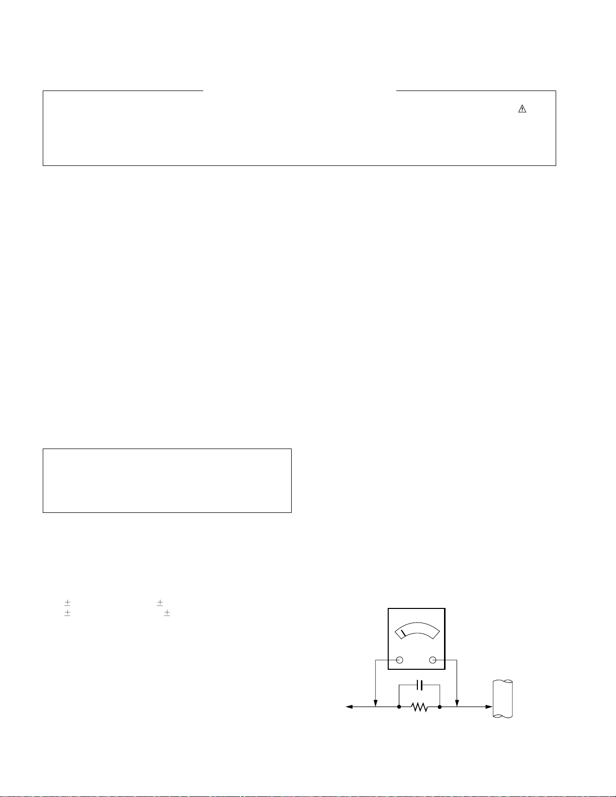
Leakage Current Hot Check (See below Figure)
Plug the AC cord directly into the AC outlet.
Do not use a line Isolation Transformer during this check.
Connect 1.5K/10watt resistor in parallel with a 0.15uF capacitor
between a known good earth ground (Water Pipe, Conduit, etc.)
and the exposed metallic parts.
Measure the AC voltage across the resistor using AC voltmeter
with 1000 ohms/volt or more sensitivity.
Reverse plug the AC cord into the AC outlet and repeat AC voltage
measurements for each exposed metallic part. Any voltage
measured must not exceed 0.75 volt RMS which is corresponds to
0.5mA.
In case any measurement is out of the limits specified, there is
possibility of shock hazard and the set must be checked and
repaired before it is returned to the customer.
Leakage Current Hot Check circuit
The source of X-RAY RADIATION in this TV receiver is the High
Voltage Section and the LCD PANEL.
For continued X-RAY RADIATION protection, the replacement
panel must be the same type panel as specified in the
Replacement Parts List.
IMPORTANT SAFETY NOTICE
0.15uF
To Instrument's
exposed
METALLIC PARTS
AC Volt-meter
1.5 Kohm/10W
Good Earth Ground
such as WATER PIPE,
CONDUIT etc.

- 4 -
CAUTION: Before servicing receivers covered by this service
manual and its supplements and addenda, read and follow the
SAFETY PRECAUTIONS on page 3 of this publication.
NOTE: If unforeseen circumstances create conflict between the
following servicing precautions and any of the safety precautions on
page 3 of this publication, always follow the safety precautions.
Remember: Safety First.
General Servicing Precautions
1. Always unplug the receiver AC power cord from the AC power
source before;
a. Removing or reinstalling any component, circuit board
module or any other receiver assembly.
b. Disconnecting or reconnecting any receiver electrical plug or
other electrical connection.
c. Connecting a test substitute in parallel with an electrolytic
capacitor in the receiver.
CAUTION: A wrong part substitution or incorrect polarity
installation of electrolytic capacitors may result in an
explosion hazard.
2. Test high voltage only by measuring it with an appropriate high
voltage meter or other voltage measuring device (DVM,
FETVOM, etc) equipped with a suitable high voltage probe.
Do not test high voltage by "drawing an arc".
3. Do not spray chemicals on or near this receiver or any of its
assemblies.
4. Unless specified otherwise in this service manual, clean
electrical contacts only by applying the following mixture to the
contacts with a pipe cleaner, cotton-tipped stick or comparable
non-abrasive applicator; 10% (by volume) Acetone and 90% (by
volume) isopropyl alcohol (90%-99% strength)
CAUTION: This is a flammable mixture.
Unless specified otherwise in this service manual, lubrication of
contacts in not required.
5. Do not defeat any plug/socket B+ voltage interlocks with which
receivers covered by this service manual might be equipped.
6. Do not apply AC power to this instrument and/or any of its
electrical assemblies unless all solid-state device heat sinks are
correctly installed.
7. Always connect the test receiver ground lead to the receiver
chassis ground before connecting the test receiver positive
lead.
Always remove the test receiver ground lead last.
8. Use with this receiver only the test fixtures specified in this
service manual.
CAUTION: Do not connect the test fixture ground strap to any
heat sink in this receiver.
Electrostatically Sensitive (ES) Devices
Some semiconductor (solid-state) devices can be damaged easily
by static electricity. Such components commonly are called
Electrostatically Sensitive (ES) Devices. Examples of typical ES
devices are integrated circuits and some field-effect transistors and
semiconductor "chip" components. The following techniques
should be used to help reduce the incidence of component
damage caused by static by static electricity.
1. Immediately before handling any semiconductor component or
semiconductor-equipped assembly, drain off any electrostatic
charge on your body by touching a known earth ground.
Alternatively, obtain and wear a commercially available
discharging wrist strap device, which should be removed to
prevent potential shock reasons prior to applying power to the
unit under test.
2. After removing an electrical assembly equipped with ES
devices, place the assembly on a conductive surface such as
aluminum foil, to prevent electrostatic charge buildup or
exposure of the assembly.
3. Use only a grounded-tip soldering iron to solder or unsolder ES
devices.
4. Use only an anti-static type solder removal device. Some solder
removal devices not classified as "anti-static" can generate
electrical charges sufficient to damage ES devices.
5. Do not use freon-propelled chemicals. These can generate
electrical charges sufficient to damage ES devices.
6. Do not remove a replacement ES device from its protective
package until immediately before you are ready to install it.
(Most replacement ES devices are packaged with leads
electrically shorted together by conductive foam, aluminum foil
or comparable conductive material).
7. Immediately before removing the protective material from the
leads of a replacement ES device, touch the protective material
to the chassis or circuit assembly into which the device will be
installed.
CAUTION: Be sure no power is applied to the chassis or circuit,
and observe all other safety precautions.
8. Minimize bodily motions when handling unpackaged
replacement ES devices. (Otherwise harmless motion such as
the brushing together of your clothes fabric or the lifting of your
foot from a carpeted floor can generate static electricity
sufficient to damage an ES device.)
General Soldering Guidelines
1. Use a grounded-tip, low-wattage soldering iron and appropriate
tip size and shape that will maintain tip temperature within the
range or 500
F to 600 F.
2. Use an appropriate gauge of RMA resin-core solder composed
of 60 parts tin/40 parts lead.
3. Keep the soldering iron tip clean and well tinned.
4. Thoroughly clean the surfaces to be soldered. Use a mall wirebristle (0.5 inch, or 1.25cm) brush with a metal handle.
Do not use freon-propelled spray-on cleaners.
5. Use the following unsoldering technique
a. Allow the soldering iron tip to reach normal temperature.
(500
F to 600 F)
b. Heat the component lead until the solder melts.
c. Quickly draw the melted solder with an anti-static, suction-
type solder removal device or with solder braid.
CAUTION: Work quickly to avoid overheating the
circuitboard printed foil.
6. Use the following soldering technique.
a. Allow the soldering iron tip to reach a normal temperature
(500
F to 600 F)
b. First, hold the soldering iron tip and solder the strand against
the component lead until the solder melts.
c. Quickly move the soldering iron tip to the junction of the
component lead and the printed circuit foil, and hold it there
only until the solder flows onto and around both the
component lead and the foil.
CAUTION: Work quickly to avoid overheating the circuit
board printed foil.
d. Closely inspect the solder area and remove any excess or
splashed solder with a small wire-bristle brush.
SERVICING PRECAUTIONS

- 5 -
IC Remove/Replacement
Some chassis circuit boards have slotted holes (oblong) through
which the IC leads are inserted and then bent flat against the
circuit foil. When holes are the slotted type, the following technique
should be used to remove and replace the IC. When working with
boards using the familiar round hole, use the standard technique
as outlined in paragraphs 5 and 6 above.
Removal
1. Desolder and straighten each IC lead in one operation by gently
prying up on the lead with the soldering iron tip as the solder
melts.
2. Draw away the melted solder with an anti-static suction-type
solder removal device (or with solder braid) before removing the
IC.
Replacement
1. Carefully insert the replacement IC in the circuit board.
2. Carefully bend each IC lead against the circuit foil pad and
solder it.
3. Clean the soldered areas with a small wire-bristle brush.
(It is not necessary to reapply acrylic coating to the areas).
"Small-Signal" Discrete Transistor
Removal/Replacement
1. Remove the defective transistor by clipping its leads as close as
possible to the component body.
2. Bend into a "U" shape the end of each of three leads remaining
on the circuit board.
3. Bend into a "U" shape the replacement transistor leads.
4. Connect the replacement transistor leads to the corresponding
leads extending from the circuit board and crimp the "U" with
long nose pliers to insure metal to metal contact then solder
each connection.
Power Output, Transistor Device
Removal/Replacement
1. Heat and remove all solder from around the transistor leads.
2. Remove the heat sink mounting screw (if so equipped).
3. Carefully remove the transistor from the heat sink of the circuit
board.
4. Insert new transistor in the circuit board.
5. Solder each transistor lead, and clip off excess lead.
6. Replace heat sink.
Diode Removal/Replacement
1. Remove defective diode by clipping its leads as close as
possible to diode body.
2. Bend the two remaining leads perpendicular y to the circuit
board.
3. Observing diode polarity, wrap each lead of the new diode
around the corresponding lead on the circuit board.
4. Securely crimp each connection and solder it.
5. Inspect (on the circuit board copper side) the solder joints of
the two "original" leads. If they are not shiny, reheat them and if
necessary, apply additional solder.
Fuse and Conventional Resistor
Removal/Replacement
1. Clip each fuse or resistor lead at top of the circuit board hollow
stake.
2. Securely crimp the leads of replacement component around
notch at stake top.
3. Solder the connections.
CAUTION: Maintain original spacing between the replaced
component and adjacent components and the circuit board to
prevent excessive component temperatures.
Circuit Board Foil Repair
Excessive heat applied to the copper foil of any printed circuit
board will weaken the adhesive that bonds the foil to the circuit
board causing the foil to separate from or "lift-off" the board. The
following guidelines and procedures should be followed whenever
this condition is encountered.
At IC Connections
To repair a defective copper pattern at IC connections use the
following procedure to install a jumper wire on the copper pattern
side of the circuit board. (Use this technique only on IC
connections).
1. Carefully remove the damaged copper pattern with a sharp
knife. (Remove only as much copper as absolutely necessary).
2. carefully scratch away the solder resist and acrylic coating (if
used) from the end of the remaining copper pattern.
3. Bend a small "U" in one end of a small gauge jumper wire and
carefully crimp it around the IC pin. Solder the IC connection.
4. Route the jumper wire along the path of the out-away copper
pattern and let it overlap the previously scraped end of the good
copper pattern. Solder the overlapped area and clip off any
excess jumper wire.
At Other Connections
Use the following technique to repair the defective copper pattern
at connections other than IC Pins. This technique involves the
installation of a jumper wire on the component side of the circuit
board.
1. Remove the defective copper pattern with a sharp knife.
Remove at least 1/4 inch of copper, to ensure that a hazardous
condition will not exist if the jumper wire opens.
2. Trace along the copper pattern from both sides of the pattern
break and locate the nearest component that is directly
connected to the affected copper pattern.
3. Connect insulated 20-gauge jumper wire from the lead of the
nearest component on one side of the pattern break to the lead
of the nearest component on the other side.
Carefully crimp and solder the connections.
CAUTION: Be sure the insulated jumper wire is dressed so the
it does not touch components or sharp edges.
- 6 -
1. Application range
This specification is applied to LP62C chassis.
2. Requirement for Test
Testing for standard of each part must be followed in below
condition.
(1) Temperature : 25°C±5°C(77±9°F), CST : 40±5
(2) Humidity : 65%±10%
(3) Power : Standard input voltage (AC 100-240V, 50/60Hz)
*Standard Voltage of each products is marked by models
(4) Specification and performance of each parts are followed
each drawing and specification by part number in
accordance with BOM.
(5) The receiver must be operated for about 20 minutes prior
to the adjustment.
3. Test method
3.1 Performance : LGE TV test method followed
3.2 Demanded other specification
Safety : CE, IEC Specification
EMC : CE, IEC
SPECIFICATION
NOTE : Specifications and others are subject to change without notice for improvement
.
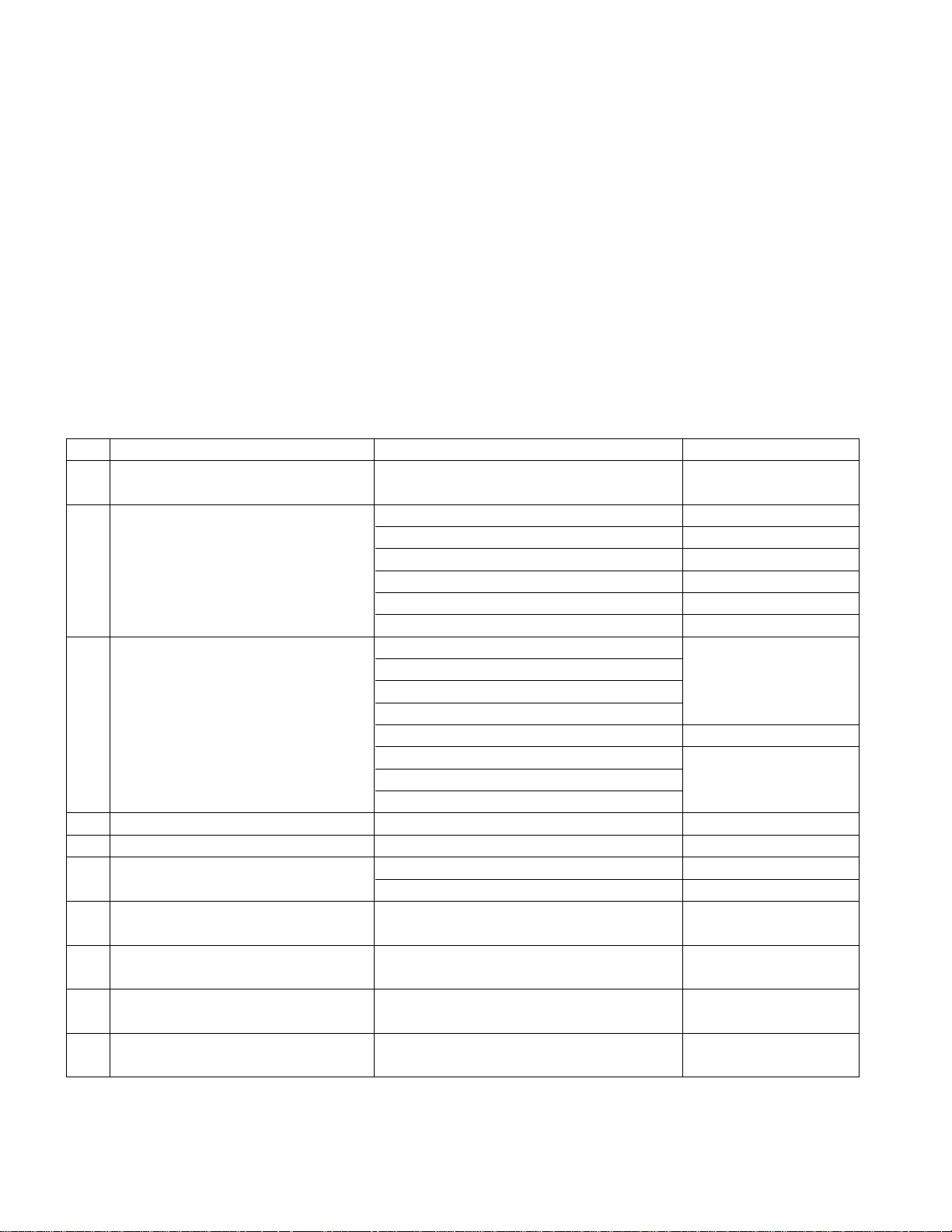
4. General TV Specification
No Item Specification Remark
1. Video input applicable system PAL-D/K, B/G, I, NTSC-M, SECAM,
NTSC 4.43
2. Receivable Broadcasting System 1) PAL/SECAM BG
2) PAL/SECAM DK
3) PAL I/I
4) SECAM L/L' only ZH
5) PAL-N/M
6) NTSC M only TH
3. RF Input Channel VHF : E2 ~ E12 PAL
UHF : E21 ~ E69
CATV : S1 ~ S20
HYPER : S21~ S47
L/L' : B, C, D FRANCE
VHF : 2~13 NTSC
UHF : 14~69
CATV : 1~125
4. Input Voltage AC 100 ~ 240 V/50Hz, 60Hz
5. Market Worldwide
6. Active Screen Size 940.3 mm(diagonal) 37.02 inches
1067.308 mm (diagonal) 42.02 inches
7. Tuning System FVS 100 program
FS
8. Operating Environment 1) Temp : 0 ~ 40 deg
2) Humidity : 10 ~ 90 %RH
9. Storage Environment 1) Temp : -20 ~ 50 deg
2) Humidity : 10 ~ 90 %RH
10. Display LCD Module 32"/42" : LPL
37" : AUO, LPL
- 7 -
5. General Specification
6. Set Optical Feature
6.1. 37LC2R-TH/42LC2R-TH
No Item Specification Remark
1 Panel 37", 42" TFT WXGA LCD
2 Frequency range H : 31 ~ 61KhzV : 56 ~ 75Hz PC Input
3 Control Function 1) Contrast/Brightness
2) H-Position / V-Position
3) Tracking : Clock / Phase
4) Auto Configure
5) Reset
4 Component Jack Y/Pb/Pr : 1EA ZH
(480i/576i/480p/576p/720p/1080i) Y/Pb/Pr : 2EA TH
5 Power ON LED Power consumption
White ≤ 190W(37")
≤ 230W(42")
Stand by RED ≤ 1W
6 LCD Module Outline 37" 877.0 x 516.8 x 55.5 (H)mmx(V)mmx(D)mm
Dimension 42" 1006 x 610 x 56
Pixel Pitch 37" 0.200 x 0.600 x RGB
42" 0.227 x 0.681 x RGB
Pixel Format 1366 x 768 Pixels RGB strip arrangement
Coating Hard coating(3H), Anti-glare treatment of
the front polarizer,
Back Light 37" 16CCFL
42" 20CCFL
No Parameter Symbol Value Unit Remark
Min Typ Max
1. Contrast Ratio CR 37" 800 1200 (*) Normal Mode
42" 700 1000
- 100IRE Full white window pattern
- APC : Clear (Dynamic)
2. Surface Luminance, LWH 360 450
Cd/m2(*) Normal Mode
white
- 100IRE Full white window pattern
- APC : Clear (Dynamic)
3. White Coordinate Normal X axis 0.280 0.283 0.286 - 85IRE Full White Pattern
Y axis 0.295 0.298 0.301 - APC : Standard
Cool X axis 0.271 0.274 0.277
Y axis 0.283 0.286 0.289
Warm X axis 0.300 0.303 0.306
Y axis 0.316 0.319 0.322
4. Color Temperature Normal 8300 9300 10300 - 85IRE Full White Pattern
Warm 6200 7200 8200 - APC : Standard
Cool 10000 11000 12000
5. Color pull in Range PAL -500 +500 Hz
NTSC -500 +500 Hz
6. Color killer Sensitivity -80 dBm
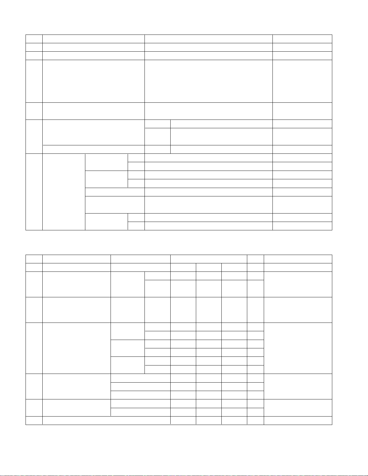
- 8 -
6.2. 37LC2R-TH/37LC2R-ZH(Only AUO Module)
No Parameter Symbol Value Unit Remark
Min Typ Max
1. Contrast Ratio CR 32", 37" 800 1200 (*) Normal Mode
42" 700 1000
- 100IRE Full white window pattern
- APC : Clear (Dynamic)
2. Surface Luminance, LWH 360 450
Cd/m2(*) Normal Mode
white
- 100IRE Full white window pattern
- APC : Clear (Dynamic)
3. White Coordinate Normal X axis 0.280 0.283 0.286 - 85IRE Full White Pattern
Y axis 0.295 0.298 0.301 - APC : Standard
Cool X axis 0.271 0.274 0.277
Y axis 0.283 0.286 0.289
Warm X axis 0.300 0.303 0.306
Y axis 0.316 0.319 0.322
4. Color Temperature Normal 8300 9300 10300 - 85IRE Full White Pattern
Warm 6200 7200 8200 - APC : Standard
Cool 10000 11000 12000
5. Color pull in Range PAL -500 +500 Hz
NTSC -500 +500 Hz
6. Color killer Sensitivity -80 dBm
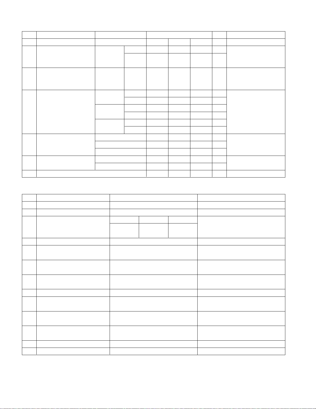
7. Model Specification
No Item Specification Remark
1. Market N-EU
2. Broadcasting system PAL BG/I/DK, NTSC-M
3. Available Channel BAND PAL NTSC
VHF/UHF C1 ~ C69 2~83
CATV S1 ~ S47 1~71
4. Receiving system Upper Heterodyne
5. SCART Jack(0EA) PAL, SECAM, NTSC
6. Video Input (2EA) PAL, SECAM, NTSC 4 System :
PAL, SECAM, NTSC, PAL60
7. S-Video Input (2EA) PAL, SECAM, NTSC 4 System :
PAL, SECAM, NTSC, PAL60
8. Component Input (1EA) Y/Cb/Cr, Y/ Pb/Pr
9. RGB Input (1EA) RGB-PC,
RGB-DTV
10. HDMI Input (2EA) HDMI-PC
HDMI-DTV
11. Audio Input (4EA) PC Audio, Component (1EA),
AV (2EA) L/R Input
12. Wired Control (1EA)
13. Audio variable out(1EA)
- 9 -
8. Component Video Input (Y, PB, PR)
No Resolution H-freq(kHz) V-freq.(kHz) Pixel clock(MHz) Remarks
1. 720 x 480 15.73 59.94 13.500 SDTV, DVD 480I(525I)
2. 720 x 480 15.75 60.00 13.514 SDTV, DVD 480I(525I)
3. 720 x 576 15.625 50.00 13.500 SDTV, DVD 576I(625I)
4. 720 x 480 31.47 59.94 27.000 SDTV 480P
5. 720 x 480 31.50 60.00 27.027 SDTV 480P
6. 720 x 576 31.25 50.00 27.000 SDTV 576P
7. 1280 x 720 44.96 59.94 74.176 HDTV 720P
8. 1280 x 720 45.00 60.00 74.250 HDTV 720P
9. 1280 x 720 37.50 50.00 74.25 HDTV 720P 50Hz
10. 1920 x 1080 33.72 59.94 74.176 HDTV 1080I
11. 1920 x 1080 33.75 60.00 74.250 HDTV 1080I
12. 1920 x 1080 28.125 50.00 74.250 HDTV 1080I 50Hz
9. RGB Input ( PC )
No Resolution H-freq(kHz) V-freq.(kHz) Pixel clock(MHz) Remarks
1 720 x 400 31.469 70.08 28.32 DOS
2. 640 x 480 31.469 59.94 25.17 VESA(VGA)
3 640 x 480 37.500 75.00 31.50 VESA(VGA)
4 800 x 600 37.879 60.31 40.00 VESA(SVGA)
5 800 x 600 46.875 75.00 49.50 VESA(SVGA)
6 832 x 624 49.725 74.55 57.28 Macintosh
7 1024 x 768 48.363 60.00 65.00 VESA(XGA)
8 1024 x 768 56.476 70.06 75.00 VESA(XGA)
9 1024 x 768 60.023 75.02 78.75 VESA(XGA)
10 1280 x 768 47.693 59.99 80.125 WXGA(42XGA,50", 60")
11 1360 x 768 47.700 60.00 84.62 WXGA(42XGA,50", 60")
12 1366 x 768 47.700 60.00 84.62 WXGA(42XGA,50", 60")
10. RGB input ( DTV )
No Resolution H-freq(kHz) V-freq.(kHz) Pixel clock(MHz) Remarks
1. 720 x 480 31.47 59.94 27.000 SDTV 480P
2. 720 x 480 31.50 60.00 27.027 SDTV 480P
3. 720 x 576 31.25 50.00 27.000 SDTV 576P
4. 1280 x 720 44.96 59.94 74.176 HDTV 720P
5. 1280 x 720 45.00 60.00 74.250 HDTV 720P
6. 1280 x 720 37.50 50.00 74.25 HDTV 720P 50Hz
7. 1920 x 1080 33.72 59.94 74.176 HDTV 1080I
8. 1920 x 1080 33.75 60.00 74.250 HDTV 1080I
9. 1920 x 1080 28.125 50.00 74.250 HDTV 1080I 50Hz
- 10 -
11. HDMI Input ( PC )
No Resolution H-freq(kHz) V-freq.(kHz) Pixel clock(MHz) Remarks
1 720 x 400 31.469 70.08 28.32 DOS
2 640 x 480 31.469 59.94 25.17 VESA(VGA)
3 640 x 480 37.500 75.00 31.50 VESA(VGA)
4 800 x 600 37.879 60.31 40.00 VESA(SVGA)
5 800 x 600 46.875 75.00 49.50 VESA(SVGA)
6. 832 x 624 49.725 74.55 57.28 Macintosh
7 1024 x 768 48.363 60.00 65.00 VESA(XGA)
8 1024 x 768 56.476 70.06 75.00 VESA(XGA)
9 1024 x 768 60.023 75.02 78.75 VESA(XGA)
10 1280 x 768 47.693 59.99 80.125 WXGA(42XGA,50", 60")
11 1360 x 768 47.700 60.00 84.62 WXGA(42XGA,50", 60")
12 1366 x 768 47.700 60.00 84.62 WXGA(42XGA,50", 60")
12. HDMI input ( DTV )
13. Mechanical Specification
13.1. 37LC2R
No Resolution H-freq(kHz) V-freq.(kHz) Pixel clock(MHz) Remarks
1. 720 x 480 31.47 59.94 27.000 SDTV 480P
2. 720 x 480 31.50 60.00 27.027 SDTV 480P
3. 720 x 576 31.25 50.00 27.000 SDTV 576P
4. 1280 x 720 44.96 59.94 74.176 HDTV 720P
5. 1280 x 720 45.00 60.00 74.250 HDTV 720P
6. 1280 x 720 37.50 50.00 74.25 HDTV 720P 50Hz
7. 1920 x 1080 33.72 59.94 74.176 HDTV 1080I
8. 1920 x 1080 33.75 60.00 74.250 HDTV 1080I
9. 1920 x 1080 28.125 50.00 74.250 HDTV 1080I 50Hz
No Item Content Remark
1. Product Width Length Height Unit
Dimension Before Packing 944 286 726 mm SET(With Stand)
After Packing 1052 383 855 mm
2. ProductWeight Only SET 31 Kg
With BOX 33.3 Kg
13.2. 42LC2R
No Item Content Remark
1. Product Width Length Height Unit
Dimension Before Packing 1054 286 813.5 mm SET(With Stand)
After Packing 1166 402 950 mm
2. ProductWeight Only SET 37 Kg
With BOX 42.3 Kg
- 11 -
ADJUSTMENT INSTRUCTION
1. Application Range
This spec. sheet is applied to all of the LP62A/B/C
chassis(H3-High) manufactured at LG TV Plant all over the
world.
2. Specification
2.1 Because this is not a hot chassis, it is not necessary to
use an isolation transformer. However, the use of isolation
transformer will help to protect test instruments.
2.2 Adjustment must be done in the correct sequence.
2.3 The adjustment must be performed at 25±5°C
temperature and 65±10% relative humidity if there is no
specified designation.
2.4 The input voltage of the receiver must be kept between
100~220V, 50/60Hz.
2.5 Before adjustment, execute Heat-Run for 30 minutes at
RF no signal
3. Adjustment items
3.1 PCB assembly adjustment items
• Channel memory
- Download the channel data from BOM to EEPROM by
using LGIDS.
• Option adjustment following BOM
- Tool Option1
- Tool Option2
- Area Option
(Fig. 1)
1) Push the ADJ key in the Adjust Remocon.
2) Input the Option Number that was specified in the BOM,
into the Shipping area.
3) Select "Tool Option1/ Tool Option2/ Area Option" by using
/ (CH+/-) key , and press the number key(0~9)
consecutively
ex) If the value of Tool Option1 is 7, input the data using
number key "7" (Fig. 1)
3.2 SET assembly adjustment items
• Auto AV(ZH-AV3, TH-AV1) Color Balance
• Aging (by Power on key)
• Adjustment of White Balance
• Auto Component Color Balance adjustment
- Standard equipment : MSPG925FA
• Auto RGB Color Balance adjustment
- Standard equipment : MSPG925FA
4. EDID
Caution
* Use the proper signal cable for EDID Download
- Analog EDID : Pin3 exists
- Digital EDID : Pin3 exists
=> Caution: - Never connect HDMI & DVI-D & DVI-A Cable at
the same time.
- Use the proper cables below for EDID Writing
4.1 EDID Data
4.1.1. ANALOG(256 Bytes )
• BLOCK1 (128BYTE)
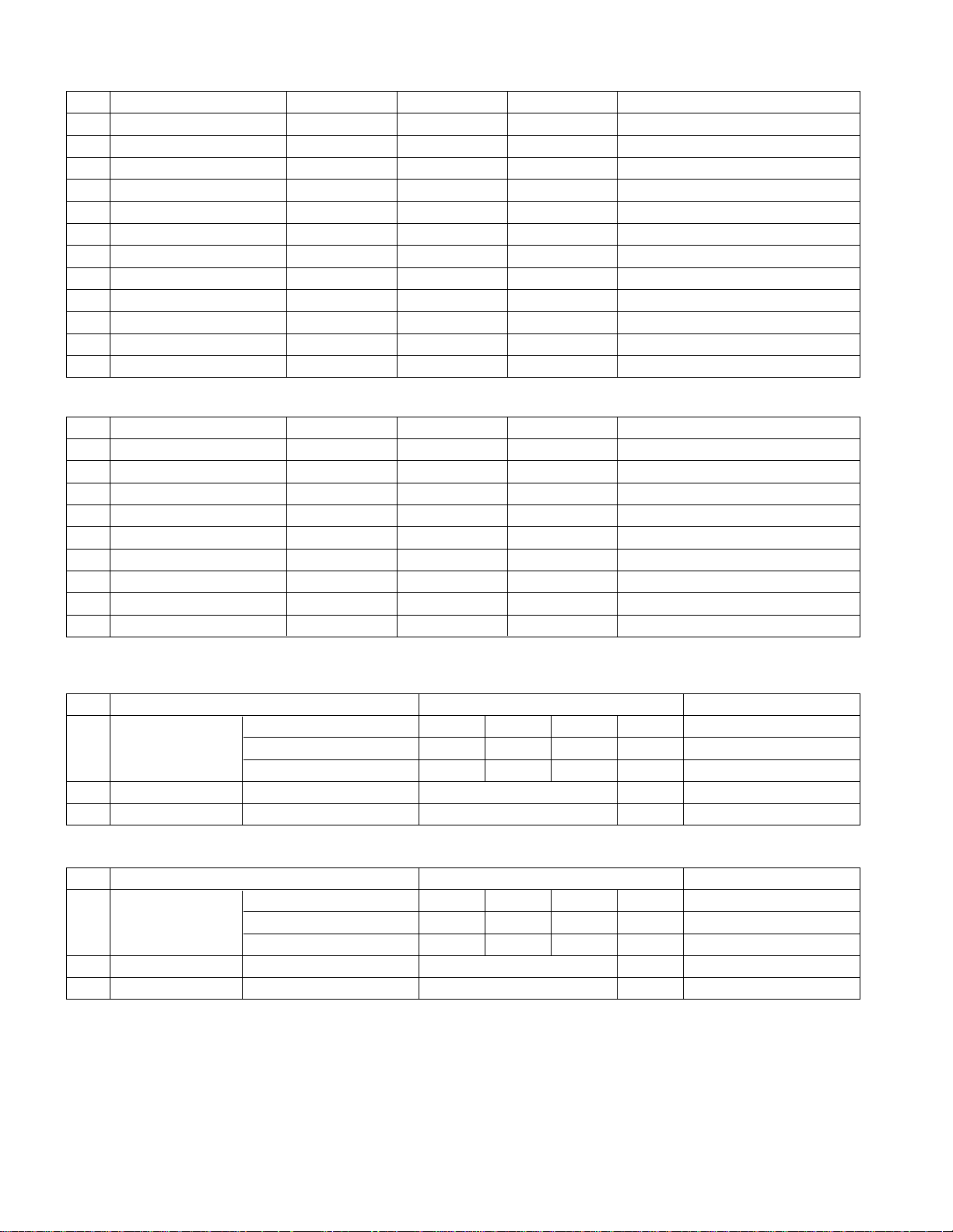
4.1.2. HDMI(256 Bytes )
• BLOCK1 (128BYTE)
BLOCK2 (128BYTE)
=> Detail EDID Options are below (a, b, c, d, e)
a. Product ID
b. Serial No : Controlled on production line
c. Month, Year : Controlled on production line:
ex) Montly : '03' => '03'
Year : '2005' => '0F'
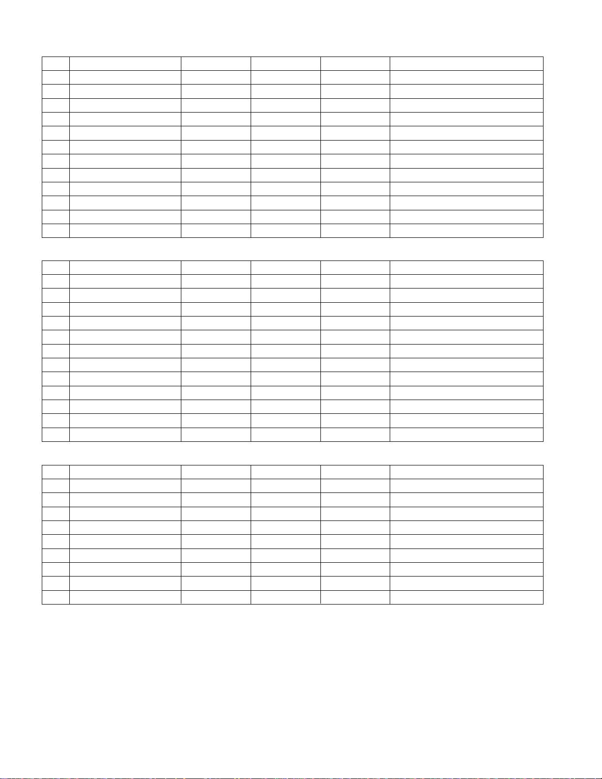
00 01 02 03 04 05 06 07 08 09 0A 0B 0C 0D 0E 0F
00 00 FF FF FF FF FF FF 00 1E 6D
10 01 03 01 46 27 78 EA D9 B0 A3 57 49 9C 25
20 11 49 4B A5 6E 80 31 40 01 01 01 01 45 40 01 01
30 61 40 01 01 01 01 1B 21 50 A0 51 00 1E 30 48 88
40 35 00 BC 88 21 00 00 1C 4E 1F 00 80 51 00 1E 30
50 40 80 37 00 BC 88 21 00 00 18 00 00 00 FD 00 38
60 4B 1F 3D 09 00 0A 20 20 20 20 20 20
70 00 99
00 01 02 03 04 05 06 07 08 09 0A 0B 0C 0D 0E 0F
00 00 FF FF FF FF FF FF 00 1E 6D
10 01 03 80 46 27 78 EA D9 B0 A3 57 49 9C 25
20 11 49 4B A5 6E 80 31 40 01 01 01 01 45 40 01 01
30 61 40 01 01 01 01 1B 21 50 A0 51 00 1E 30 48 88
40 35 00 BC 88 21 00 00 1C 4E 1F 00 80 51 00 1E 30
50 40 80 37 00 BC 88 21 00 00 18
60 00 00 00
FD
70 00 38 4B 1F 3D 09 00 0A 20 20 20 20 20 20 01 14
00 01 02 03 04 05 06 07 08 09 0A 0B 0C 0D 0E 0F
00 02 03 24 F1 49 85 04 02 01 03 11 12 13 14 23 09
10 07 07 23 09 07 07 23 09 07 07 83 01 00 00 65 03
20 0C 00 10 00 01 1D 00 80 51 D0 1C 20 40 80 35 00
30 BC 88 21 00 00 1E 8C 0A D0 8A 20 E0 2D 10 10 3E
40 96 00 13 8E 21 00 00 18 2A 12 00 10 41 43 17 20
50 28 60 35 00 00 00 32 00 00 1C 01 1D 80 18 71 1C
60 16 20 58 2C 25 00 C4 8E 21 00 00 9E 00 00 00 00
70 00 00 00 00 00 00 00 00 00 00 00 00 00 00 00 6B
LP62x
Cortez Version x.xx
Panel Used XX hr.
Tool Option1 7
Tool Option2 161
Area Option 16
:
:
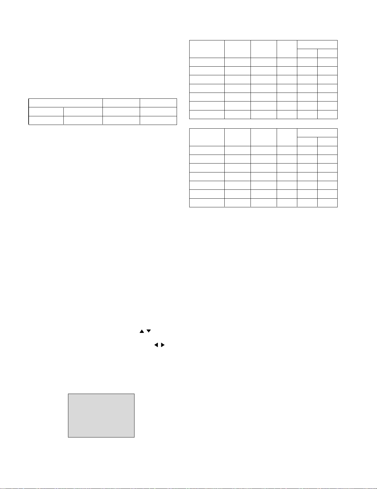
Model Name
Product ID
Product ID
Dec Hex EDID table
37LC2R 30059(A) 30059 756B 6B75
30060(D) 30060 756C 6C75
42LC2R 40023(A) 40023 9C57 579C
40024(D) 40024 9C58 589C
a
a
c
d
d
b
c
d
d
b
- 12 -
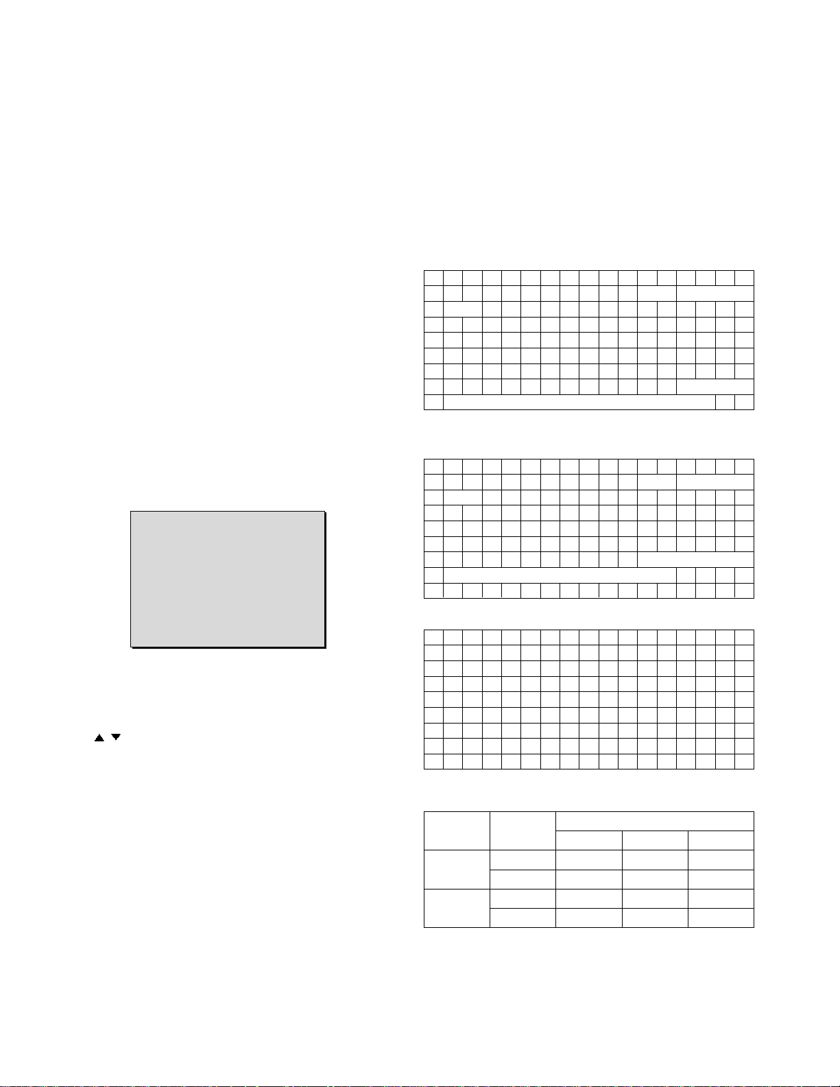
d. Model Name/Monitor Name:
e. Checksum: Changeable by total EDID data
5. ADC Calibration
5.1 Adjustment of RF/AV/S-VIDEO
* Required Equipments
• Remote controller for adjustment
• 802F Pattern Generator, Master (MSPG-925FA), etc.
• MSPG-925FA Pattern Generator
(Which has Video Signal: 100% Color Bar Pattern
shown in Fig. 1)
=> Model : 202 / Pattern: 33 (PAL : ZH, TH)
Model : 201 / Pattern : 33 (NTSC : MH)
(Fig. 1)
5.1.1 Method of Auto RF/AV/S-VIDEO Color Balance.
1) Press the FRONT-AV KEY on R/C for converting input
mode.
2) Input the Video Signal: 100% Color Bar signal into
AV3(ZH), AV1(TH), VIDEO1(MH)
3) Set the PSM to Standard mode in the Picture menu.
4) Press INSTART key on R/C for adjustment.
5) Press the
(Vol.+) key to operate the set, then it becomes
automatically
6) Auto-RGB OK means the adjustment is completed
5.1.2 Requirement
• This AV color balance adjustment should be performed
before White Balance Adjustment.
• After color balance adjustment, You must push "power on"
key. ("Power on" key is "Access Heat_run mode")
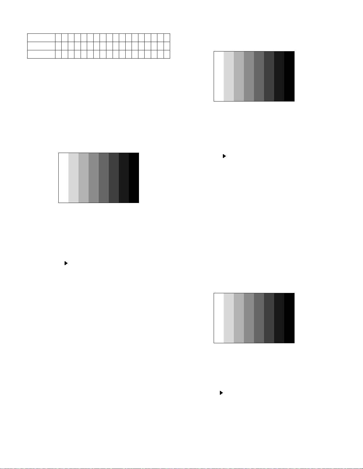
5.2 Adjustment of Component.
* Required Equipments
• Remote controller for adjustment
• 802F Pattern Generator, Master (MSPG-925FA), etc.
• MSPG-925FA Pattern Generator
(Which has 720p YPbPr signal : 100% Color Bar
Pattern shown in Fig. 2 )
=> Model: 217 / Pattern: 33
• It is very import to use correct adjustment pattern like
Fig. 2.
- Within the pattern, color sequence should be aligned
: W-Y-C-G-M-R-BLUE-BLACK
(If color sequence is reversed (Black -> ... -> White),
reverse the pattern with REV key, when using
Master pattern generator like MSPG-925)
- If Minimum Black Level and/or Maximum White
Level is not correct, Do select 100% Color Bar
Pattern.
(Fig. 2)
5.2.1 Method of Auto Component Color Balance
1) Input the Component 720p 100% Color Bar(MSPG-925FA
model:217, pattern:33) signal into Component.
(ZH : component , TH/MH : component 1 or 2)
2) Set the PSM to Standard mode in the Picture menu.
3) Press the INSTART key on R/C for adjustment.
4) Press the
(Vol. +) key to operate the set , then it
becomes automatically.
5) Auto-RGB OK means the adjustment is completed.
5.3 Adjustment of RGB
* Required Equipments
• Remote controller for adjustment
• 802F Pattern Generator, Master (MSPG-925FA), etc.
• MSPG-925FA Pattern Generator
(Which has XGA [1024x768] 60Hz PC Format output
signal : 100% Color Bar Pattern shown in Fig. 3 )
• It is very import to use correct adjustment pattern like
Fig. 10.
- Within the pattern, color sequence should be aligned
: W-Y-C-G-M-R-BLUE-BLACK
(If color sequence is reversed (Black ->...-> White),
reverse the pattern with REV key, when using
Master pattern generator like MSPG-925)
- If Minimum Black Level and/or Maximum White
Level is not correct, Do select 100% Color Bar
Pattern.
(Fig. 3)
5.3.1 Method of Auto RGB Color Balance
1) Input the PC 1024x768@60Hz 1/2 Black&White Pattern
(MSPG-925FA model:3, pattern:33) into RGB.
2) Set the PSM to Standard mode in Picture menu.
3) Press the INSTART key on R/C for adjustment.
4) Press the
(Vol. +) key operate To set , then it becomes
automatically.
5) Auto-RGB OK means adjustment is completed.
Model Name
37LC2R-TH 00 00 00 FC 00 33 37 4C 43 32 52 2D 54 48 0A 20 20 20
42LC2R-TH 00 00 00 FC 00 34 32 4C 43 32 52 2D 54 48 0A 20 20 20
- 13 -
=> Caution : Before White-balance, the AV ADC should
be done. (ZH:AV3, TH:AV1, MH:VIDEO1)
=> After Aging, When the procedure is changed White
balance adjustment, it will be canceled Heat_run mode
auto.
(Notice : Before White-balance, change input mode Move
to AV3(ZH) or AV1(TH) or VIDEO1(MH) by using
the FRONT-AV KEY on Remote controller.)
6. White Balance
=> Caution : - System control RS-232 Host should be "PC" for
adjustment.
- AV ADC(ZH: AV3, TH : AV1, MH: VIDEO1)
should be done before White-balance.
* Test Equipment
Color Analyzer (CA-110)
PC(For communication through RS-232C)=>UART
Baud rate : 115200
Pattern Generator (MSPG-925FA etc.)
*Target Value [ PSM: Standard(ZH/TH), CSM: Normal]
- Normal(9300K±1000K) x:283±0.015, y: 298±0.015
-Luminance(Y) AV/COMP: 250 Cd/m2 (Typ: 300 Cd/m2)
PC : 300 Cd/m2 (Typ: 350 Cd/m2)
=> Reference Value(Automatically fixed)
- Cool(11000K±1000K)
- Warm(7200K±1000K)
6.1 Manual white Balance (AV)
1) Execute CA-110 Zero Calibration.
2) Execute the SET Heat Run for 30minutes
3) As below Fig. 4, Supply 216Level (85 IRE) full screen
pattern to Video input.
37LC2R-ZH,42LC2R-ZH : AV3/AV4 (Input 50Hz),
32LB1R-TH : AV1/AV2 (Input 50Hz)
4) Press the FRONT-AV KEY on R/C for converting input
mode.
5) Set the PSM to Standard mode in Picture menu.
6) Enter the White Balance adjustment mode by pressing the
INSTART key twice(White Balance) on R/C.
7) Stick sensor to center of the screen and select each items
(Red/Green/Blue Gain and Offset) using
/ (CH+/-) key
on R/C.
8)Adjust Only High Light with R Gain/B Gain using
/ (VOL
+/-) key on R/C.
9) Adjust it until color coordination becomes as below.
X-axis : 0.283±0.003
Y-axis : 0.298±0.003
(R/G/B gain and R/G/B offset Default values are different in
according to using module )
10) Adjust High light with R/B Gain.
(Fig.4)
6.2 Auto white Balance (AV)
1) LPL Module
2) AUO Module
White balance ZH(AV3), TH(AV1) MH(VIDEO1)
MSPG925FA 216 Level (85IRE) Model : 202 Model : 201
Full screen pattern
•
Pal Video
•
NTSC Video
216 Level(85IRE)
Command1 Command2 Set ID
Data
Min Max
Input Select XB B 00 00h 90h
R-Gain J A 00 00h E0h
G-Gain J B 00 00h E0h
B-Gain J C 00 00h E0h
R-Offset J D 00 00h 90h
G-Offset J E 00 00h 90h
B-Offset J F 00 00h 90h
Command1 Command2 Set ID
Data
Min Max
Input Select XB B 00 00h 90h
R-Gain J A 00 00h E0h
G-Gain J B 00 00h E0h
B-Gain J C 00 00h E0h
R-Offset J D 00 00h 90h
G-Offset J E 00 00h 90h
B-Offset J F 00 00h 90h

- 14 -
7. Shipping Conditions
No Item Condition Remark
1 Power Off
2 Volume Level 30
3 Main Picture Input TV
4 Main Last Channel Pr 01
5 Mute Off
6 ARC 16 : 9
7 Station Auto Programme
Manual Programme
Programme Edit
Favorite Programme None
8 Picture PSM Dynamic
Dynamic Contrast 100
Brightness 50
Colour 50
Sharpness 50
CSM Normal
XD Auto
Advanced
Reset
9 Sound SSM Flat
Off
AVL Off
Balance 0
50
50
Speaker On
10 Time Clock --:-- User control
Off time Off
On time Off
Auto sleep Off
11 Special Language English Area management
Child Lock Off
Set ID 1
XD Demo To start
12 Screen Auto config.
Manual config.
XGA/VGA mode Variable by each mode
ARC
PFP Transparency
Reset
 Loading...