


 Loading...
LG 32SE3B, 43SE3B, 49SE3B, 55SE3B, 65SE3B User Guide
...OWNER’S MANUAL
LG Digital
Signage
(MONITOR SIGNAGE)
Please read this manual carefully before operating your set and retain it for future reference.
32SE3B 32SE3KB 43SL5B 43SE3B 43SE3KB 49SL5B 49SE3B 49SE3KB 55SL5B 55SE3B 55SE3KB
65SE3B 65SE3KB
www.lg.com

ENGLISH
2 TABLE OF CONTENTS
TABLE OF CONTENTS
3 IMPORTANT PRECAUTIONS
3Electrical Power Related Precautions
4Precautions in installing the Product
4Precautions in Moving the Product
5Precautions in Using/
5 Cleaning the Product
5On Disposal (Only, Hg lamp used LCD Monitor)
6LICENSES
7ASSEMBLY AND PREPARATION
7Accessories
8Optional Accessories
10Parts and Buttons
12Connecting the Stand
13Connecting the Speakers
14Using the IR Receiver
15Portrait Layout
16Attaching and removing the LG Logo Bracket
17 Installing on a Wall
19 REMOTE CONTROL
21Displaying the Device Name Connected to an Input Port
21White Balance Adjust Menu
22Using Picture ID
23MAKING CONNECTIONS
23 Connecting to a PC
25 External Device Connection
28 USING THE MONITOR
28 Using the Input List
28 Adjusting Aspect Ratio
30 ENTERTAINMENT
30 Using the Network
30 - Connecting to a Network
32 - Network Status
32 Using the My Media
32 - Connecting USB storage devices
34 - Browsing Files
36 - Viewing Movies
39 - Viewing Photos
41 - Listening to Music
43- Viewing the Contents List
44CUSTOMIZING SETTINGS
44Accessing Main Menus
45- PICTURE Settings
48- AUDIO Settings
49- TIME Settings
50- OPTION Settings
53- NETWORK Settings
54 TROUBLESHOOTING
56 PRODUCT SPECIFICATIONS
68 IR CODES
70TO CONTROL MULTIPLE PRODUCTS
70Connecting the Cable
71RS-232C Configurations
71- 4P Cable
71- RS-232C Cable
71Communication Parameter
72Command Reference List
74 Transmission / Receiving Protocol
WARNING: This product contains chemicals known to the State of California to cause cancer and birth defects or other reproductive harm. Wash hands after handling.
IMPORTANT PRECAUTIONS |
3 |
•• Do not insert metal or other conductive materials into the product openings. Additionally, do not touch the power cable right after plugging into the wall input terminal.
►►You may be electrocuted.
•• The appliance coupler is used as the disconnect device.
•• Please make sure the device is installed near the wall outlet to which it is connected and that the outlet is easily accessible.
•• Do not unplug the power cord while the product is in use.
►►Electrical shock can damage the product.
•• As long as this unit is connected to the AC wall outlet, it is not disconnected from the AC power source even if the unit is turned off.
ENGLISH

ENGLISH
4 IMPORTANT PRECAUTIONS
Precautions in installing the Product
 WARNING
•• Keep away from heat sources like eaters or open flames.
►►Electrical shock, fire, malfunction or deformation may occur.
•• Keep the packing anti-moisture material or vinyl packing out of the reach of children.
►►Anti-moisture material is harmful if swallowed. If swallowed by mistake, force the patient to vomit and visit the nearest hospital. Additionally, vinyl packing can cause suffocation. Keep it out of the
reach of children.
•• Do not put heavy objects on the product on sit upon it.
►►If the product collapses or is dropped, you may be injured. Children
must pay particular attention.
•• Do not leave the power or signal cable where someone can trip over it.
►►The passerby can falter, which can cause electrical shock, fire, product
breakdown or injury.
•• Install the product in a neat and dry place. Do not use near water.
►►Dust or moisture can cause electrical shock, fire or product damage.
•• Do not add accessories that have not been designed for this display.
•• If you smell smoke or other odors or hear a strange sound from the product unplug the power cord and contact LG Customer Service.
►►If you continue to use without taking proper measures, electrical
shock or fire can occur.
•• If you dropped the product or the case is broken, turn off the product and unplug the power cord.
►►If you continue to use without taking proper measures, electrical
shock or fire can occur. Contact LG Customer Service.
•• Do not drop an object on or apply impact to the product. Do not throw any toys or objects at the product.
►►It can cause injury to humans, problems to the product and damage
the display.
•• Keep out of reach of children and do not place toys near the product.
•• Make sure the product ventilation hole is not blocked. Install the product more than 10cm from the wall.
►►If you install the product too close to the wall, it may be deformed or
fire can break out due to internal heat build-up.
•• Do not cover the product with cloth or other material (eg. plastic) while plugged in.
►►The product can be deformed or fire can break out due to internal
overheating.
•• Place the product on a flat and stable surface that is large enough to support the product.
►►If the product is dropped, you may be injured or the product may
be broken.
•• Install the product where no Electromagnetic Interference occurs.
•• Keep the product away from direct sunlight.
•• Do not place the product on the floor.
►►Small Children and others may trip over it.
•• Do not install this product on a wall if it could be exposed to oil or oil mist.
►►This may damage the product and cause it to fall.
•• For displays with glossy bezels the user should consider the placement of the display as the bezel may cause disturbing reflections from surrounding light and bright surfaces.
Precautions in Moving the Product
 WARNING
•• Make sure to turn off the product.
••
•• When lifting or moving the product, do not hold it upside down while holding only the stand.
►►This may cause the product to fall resulting in damage or injury.
•• Do not shock the product when moving it.
►►You may be electrocuted or the product can be damaged.
•• Make sure the panel faces forward and hold it with both hands to move.
►►If you drop the product, the damaged product can cause electric
shock or fire.
•• Do not place the product face down.
►►This may damage the TFT-LCD screen.
►►The product can be damaged.

IMPORTANT PRECAUTIONS |
5 |
Precautions in Using/
Cleaning the Product
 WARNING
•• Do not attempt to disassemble, repair or modify the product yourself.
►►Fire or electric shock can occur.
►►Contact LG Customer Service for repair.
•• When cleaning the product, unplug the power cord and scrub gently with a soft cloth to prevent scratching. Do not clean with a wet cloth or spray water or other liquids directly onto the product. An electric shock may occur. (Do not use chemicals such as benzene, paint thinners or alcohol)
•• Keep the product away from water.
►►Fire or electric shock accident can occur.
•• Avoid high temperatures and humidity.
•• Do not put or store flammable substances near the product.
►►There is a danger of explosion or fire.
•• Keep the product clean at all times.
•• Take a comfortable and natural position when working with the product.
•• Take a regular break when working with the product for a long time.
•• Do not press on the panel with a hand or sharp object such as nail, pencil or pen, or make a scratch on it.
•• Keep proper distance from the product and rest from time-to-time.
►►Your vision may be impaired if you look at the product too closely
or for too long.
•• Set the appropriate resolution by referring to the User’s Guide.
•• Keep small accessories out of the reach of children.
•• Displaying a still image for long time on the monitor may leave persistent image or stain on the monitor screen. To avoid this problem, use a screen saver and power off when this product is not used. Persistent image or stain caused by long time usage are not covered by the warranty on this product.
•• Do not use products using high voltage around the Monitor. (ex. Electrical Swatter)
►►Monitor may have malfunction as its electrical shock.
•• Spray water onto a soft cloth 2 to 4 times, and use it to clean the front frame;wipe in one direction only. Too much moisture may cause staining.
On Disposal (Only, Hg lamp used LCD Monitor)
•• The fluorescent lamp used in this product contains a small amount of mercury.
•• Do not dispose of this product with general household waste.
•• Disposal of this product must be carried out in accordance to the regulations of your local authority.
ENGLISH

ENGLISH
6 LICENSES
LICENSES
Supported licenses may differ by model. For more information of the licenses, visit www.lg.com.
The terms HDMI and HDMI High-Definition Multimedia Interface, and the HDMI logo are trademarks or registered trademarks of HDMI Licensing LLC in the United States and other countries.
This DivX Certified® device has passed rigorous testing to ensure it plays DivX® video.
To play purchased DivX movies, first register your device at vod.divx.com. Find your registration code in the DivX VOD section of your device setup menu.
DivX Certified® to play DivX® video up to HD 1080p, including premium content.
DivX®, DivX Certified® and associated logos are trademarks of DivX, LLC and are used under license.
Covered by one or more of the following U.S. patents: 7,295,673; 7,460,668; 7,515,710; 7,519,274.
Manufactured under license from Dolby Laboratories. Dolby and the double-D symbol are trademarks of Dolby Laboratories.
ASSEMBLY AND PREPARATION |
7 |
ASSEMBLY AND PREPARATION
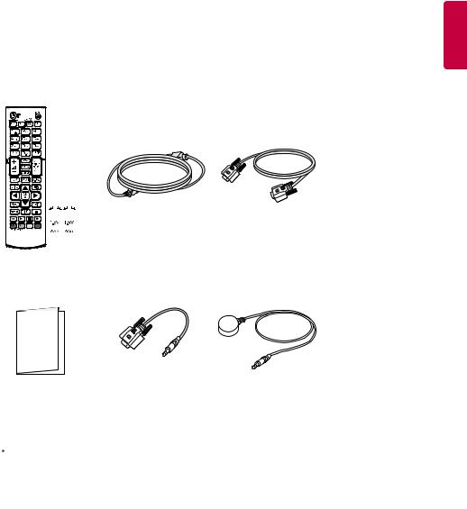
Accessories
Check your product box for the following items. If there are any missing accessories, contact the local dealer where you purchased your product. The illustrations in this manual may differ from the actual product and accessories.
ENGLISH
|
|
|
|
|
|
|
|
|
|
|
|
|
|
|
|
|
|
|
|
|
|
|
|
|
|
|
|
|
|
Remote Control, |
|
Power Cord |
D-sub 15-pin Signal |
||||||
Batteries (AAA) 2 EA |
|
Cable |
|||||||
|
|
|
|||||||
|
|
|
|
|
|
|
|
|
|
|
|
|
|
|
|
|
|
|
|
Card and the Letter of |
|
RS-232C Gender |
|
IR Receiver |
Warranty |
|
|
||
|
|
|
|
 CAUTION
•• Always use genuine components to ensure safety and product performance.
•• The product warranty will not cover damage or injury caused by the use of counterfeit components.
 NOTE
NOTE
•• The accessories provided with your product may vary depending on the model or region.
•• Product specifications or contents in this manual may be changed without prior notice due to upgrade of product functions.
•• SuperSign Software & Manual
-Downloading from the LG Electronics website.
-Visit the LG Electronics website (www.lgecommercial.com/supersign) and download the latest software for your model.
ENGLISH
8 ASSEMBLY AND PREPARATION
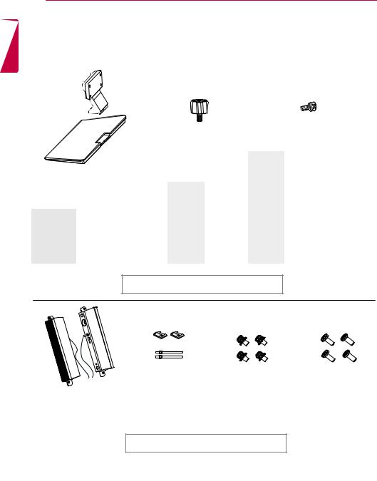
Optional Accessories
Without prior notice, optional accessories are subject to change to improve the performance of the product, and new accessories may be added. The illustrations in this manual may differ from the actual product and accessories.
|
|
|
Stand |
|
Screws |
|
||
|
|
|
|
|
|
|||
|
|
|
Spacers |
Diameter 4.0 mm x Pitch 0.7 mm |
||||
|
|
|
|
|
|
|
|
|
|
|
|
|
|
|
|
Length |
|
|
|
|
|
|
|
Model |
(including |
Quantity |
|
|
|
|
|
|
|
spring washer) |
|
|
|
|
32SE3* |
- |
|
32SE3* |
10 mm |
6 EA |
|
Stand |
|
43SE3* |
|
|
43SE3* |
14 mm |
8 EA |
|
|
43SL5B |
|
|
43SL5B |
|||
ST-322T |
32SE3* |
|
|
|
|
|
||
|
49SE3* |
|
|
49SE3* |
14 mm |
8 EA |
||
ST-432T |
43SE3*/43SL5B |
|
|
|
||||
|
49SL5B |
2 EA |
|
49SL5B |
||||
|
|
|
|
|||||
ST-492T |
49SE3*/55SE3* |
|
55SE3* |
|
|
55SE3* |
14 mm |
8 EA |
49SL5B/55SL5B |
|
55SL5B |
|
|
55SL5B |
|||
|
|
|
|
|
|
|||
ST-652T |
65SE3* |
|
65SE3* |
|
|
65SE3* |
16 mm |
8 EA |
Stand kit
Speakers |
Cable holder/ |
Screws |
SP-5000 |
Cable Tie |
Diameter 4.0 mm x Pitch |
|
|
|
|
|
0.7 mm x Length 8 mm |
|
|
(including spring washer) |
Speaker kit
(Only for **SE3B/**SL5B model)
 NOTE
NOTE
Screws
Diameter 4.0 mm x Pitch 1.6 mm x Length 10 mm
•• Cable holder/cable tie may not be available in some areas or for some models.
•• Optional accessories are available for some models. If necessary, please purchase them separately.

ASSEMBLY AND PREPARATION |
9 |
ENGLISH
Media Player |
Screws |
CD (Owner's Manual)/ |
|
Cards |
|||
MP500/ MP700 |
|
||
|
|
Media Player kit
( It may not be supported depending on the model.)
AN-WF500
Wi-Fi Dongle kit
NOTE
•• Optional accessories are available for some models. If necessary, please purchase them separately.

ENGLISH
10 ASSEMBLY AND PREPARATION
Parts and Buttons
- The image may be different according to the model
32/43/49/55SE3B |
32/43/49/55SE3KB |
43/49/55SL5B |
|
|
|
|
USB 2 V 1.0 A |
|
|
|
|
|
5 |
|
|
|
|
|
USB 1 V 1.0 A |
|
|
|
|
|
5 |
|
|
|
|
|
LAN |
|
|
|
|
|
RGB IN |
|
|
|
|
|
DVI-D IN |
|
SPEAKER |
RS-232C RS-232C |
EXT IR |
AUDIO |
AUDIO |
|
OUT |
IN |
OUT |
IN |
IN |
OUT |
Buttons
|
|
|
|
|
|
|
|
|
|
|
|
Connection |
||
(Only for |
||||
Panel |
||||
**SE3B/**SL5B |
||||
|
|
|||
model) |
|
|
||
Buttons |
Description |
INPUT |
Changes the input source. |
|
|
MENU |
Accesses the main menus, or saves your input and exits the menus. |
|
|
|
Adjust the up and down. |
|
|
|
Moves left and right. |
|
|
AUTO/SET |
Displays the current signal and mode. |
|
|
/ I |
Turns the power on or off. |
|
65SE3B 65SE3KB
ASSEMBLY AND PREPARATION 11
ENGLISH
LAN 5 V 1.0 A 5 V 1.0 A
USB 1 USB 2
|
|
|
|
RGB IN |
|
|
|
|
|
DVI-D IN |
|
SPEAKER |
RS-232C RS-232C |
EXT IR |
AUDIO |
AUDIO |
|
OUT |
IN |
OUT |
IN |
IN |
OUT |
Buttons
(Only for **SE3B model) |
Connection |
|
Panel |
Buttons |
Description |
INPUT |
Changes the input source. |
|
|
MENU |
Accesses the main menus, or saves your input and exits the menus. |
|
|
|
Adjust the up and down. |
|
|
|
Moves left and right. |
|
|
AUTO/SET |
Displays the current signal and mode. |
|
|
/ I |
Turns the power on or off. |
|
ENGLISH
12 ASSEMBLY AND PREPARATION
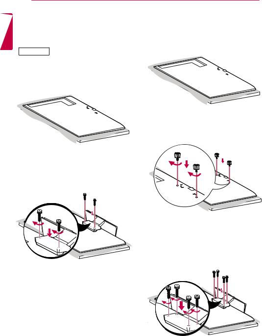
Connecting the Stand |
|
|
|
43/49/55/65SE3* |
43/49/55SL5B |
-For certain models only.
-The image may be different according to the model
32SE3*
1Place a soft cloth on the table and place the product with the screen facing downward.
1Place a soft cloth on the table and place the product with the screen facing downward.
2 Tighten stand spacers on the back of the product as shown below.
2 Use the screws to secure the stand to the back of the product as shown below.
3 Use the screws to secure the stand to the back of the product as shown below.

ASSEMBLY AND PREPARATION 13
Connecting the Speakers
-For certain models only. (Only for **SE3B/**SL5B model)
-The image may be different according to the model.
32SE3B
1Connect an input signal cable before installing the speakers.
2Mount the speakers by using screws as shown below. Make sure the power cable is disconnected before making a connection.
3Then connect the speaker cable. After installing your speakers, use holders and cable ties to organize the speaker cables.
43/49/55/65SE3B 43/49/55SL5B
1Connect an input signal cable before installing the speakers.
2Mount the speakers by using screws as shown below. Make sure the power cable is disconnected before making a connection.
3Then connect the speaker cable. After installing your speakers, use holders and cable ties to organize the speaker cables.
ENGLISH

ENGLISH
14 ASSEMBLY AND PREPARATION
NOTE |
Using the IR Receiver |
|
•• Please turn off the power before removing the cable. Connecting or removing the speaker cable while turned on may result in no sound.
-The image may be different according to the model.
This allows a remote control sensor to be placed in a custom location. Then that display can control other displays via an RS-232C cable. Install the IR receiver towards the front of the set.
 IR Receiver cable
 NOTE
NOTE
•• When you see from the back of the set, if the IR receiver cable does not face front, the signal reception range may shorten.
•• The IR receiver is made with a magnet.It is detachable at the bottom (typical installation) or back (wall installation) of the set.
•• Make sure that you unplug the power cord before connecting or removing the IR Receiver.
|
ASSEMBLY AND PREPARATION 15 |
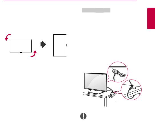
Portrait Layout |
Using Kensington Lock |
When installing in a portrait layout, rotate the |
(This is not available for all models.) |
monitor counterclockwise 90 degrees (when facing |
The Kensington security system connector is |
the screen). |
located at the back of the monitor. For more |
|
information on installation and use of this system, |
|
refer to the manual provided with the Kensington |
|
security system or visit http://www.kensington. |
|
com. |
|
Connect the Kensington security system cable |
|
between the monitor and a table. |
NOTE
Kensington security system is optional. You can obtain additional accessories from most electronics retail stores.
ENGLISH
ENGLISH
16 ASSEMBLY AND PREPARATION
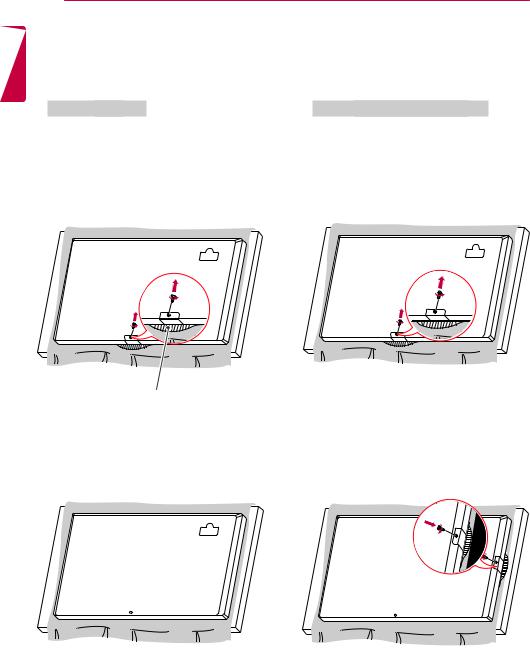
Attaching and removing the LG Logo Bracket
-For certain models only.
-The image may be different according to the model.
Removing the LG Logo
1Lay a clean cloth on the floor, and then put the monitor on it with the screen face down. Using a screwdriver, remove the screw that secures the LG Logo Bracket to the bottom rear of the monitor.
Attaching the LG Logo on the right side
1Lay a clean cloth on the floor, and then put the monitor on it with the screen face down. Using a screwdriver, remove the screw that secures the LG Logo Bracket to the bottom rear of the monitor.
LG Logo Bracket
2After removing the screw, remove the LG Logo. When re-attaching the LG Logo, repeat the process in reverse order.
2After removing the screw, remove the LG Logo. Attach the LG Logo Bracket with a screw, aligning it with the hole on the right side.

ASSEMBLY AND PREPARATION 17
Installing on a Wall |
CAUTION |
For proper ventilation, allow a clearance of 10 cm on each side and from the wall. Detailed installation instructions are available from your
dealer, see the optional Tilt Wall Mounting Bracket Installation and Setup Guide.
10 cm 
|
10 cm |
10 cm |
10 cm |
10 cm 
•• Disconnect the power cord before moving or installing the monitor to avoid risk of electric shock.
•• If you install the monitor on a ceiling or slanted wall, it may fall and result in injury. Use an authorized LG wall mount and contact your local dealer or qualified personnel to assist with the installation.
•• Do not over tighten the screws as this may damage the monitor and void your warranty.
•• Use only screws and wall mounting brackets that meet the VESA standard. Any damage or injuries caused by misuse or use of improper accessories are not covered by the warranty.
To install your monitor on a wall, attach a wall mounting bracket (optional part) to the back of the monitor.
Make sure that the wall mounting bracket is securely fixed to the monitor and to the wall.
1Use only screws and wall mounting brackets that conform to VESA standards.
2Screws which are longer than standard length may damage the inside of the monitor.
3A non-VESA standard screw may damage the product and cause the monitor to fall. LG
Electronics is not liable for any accidents related to the use of non-standard screws.
4Please use VESA standard as below.
•• 785 mm and above
*Fixing screws: Diameter 6.0 mm x Pitch
1.0mm x Length 12 mm
 NOTE
NOTE
•• The wall mount kit includes the installation guide and all necessary parts.
•• The wall mounting bracket is optional. You can obtain additional accessories from your local dealer.
•• The length of screws required may differ depending on the wall mount. Be sure to use the correct length.
•• For more information, please refer to the guide provided with the wall mount.
•• The warranty will not cover any damages caused by using the product in an excessively dusty environment.
ENGLISH
785 mm
18 ASSEMBLY AND PREPARATION
ENGLISH |
|
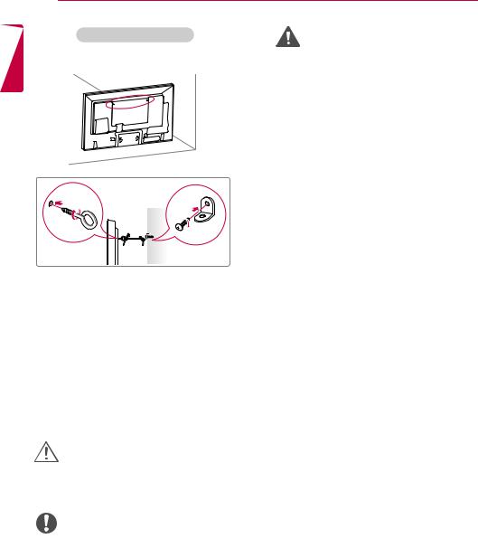
Securing the monitor to a wall (optional) |
|
|||||
Procedure may differ depending on the model. |
||||||||
|
||||||||
|
|
|
|
|
|
|
|
|
|
|
|
|
|
|
|
|
|
|
|
|
|
|
|
|
|
|
|
|
|
|
|
|
|
|
|
|
|
|
|
|
|
|
|
|
|
|
|
|
|
|
|
|
|
1Insert and tighten the eyebolts, or brackets and bolts on the back of the monitor.
- If there are already bolts inserted in the eyebolts’ position, remove the other bolts first.
2Mount the wall brackets with the bolts to the wall. Match the location of the wall bracket and the eyebolts on the rear of the monitor.
3Connect the eyebolts and wall brackets tightly with a sturdy cord.
Make sure the securing cord is horizontal with the flat surface.
CAUTION
sure that children do not climb on or hang from the monitor.
NOTE
a platform or cabinet that is large and strong enough to support the monitor securely.
•• Brackets, bolts, and cords are sold separately. You can obtain additional accessories from your local retail store.
•• The illustration shows a general example of installation and may look different from the actual product.
WARNING
monitor is not positioned in a sufficiently stable location, there is a danger that it will fall. Many injuries, particularly to children, can be avoided by taking simple precautions such as:
»»Using cabinets or stands recommended by the manufacturer.
»»Only using furniture that can safely support the monitor.
»»Ensuring the monitor is not overhanging the edge of the supporting furniture.
»»Not placing the monitor on tall furniture (for example, cupboards or bookcases) without anchoring both the furniture and the monitor to a suitable support.
»»Not placing cloth or other materials between the monitor and supporting furniture.
»»Educating children about the dangers of climbing on furniture to reach the monitor or its controls.
REMOTE CONTROL 19
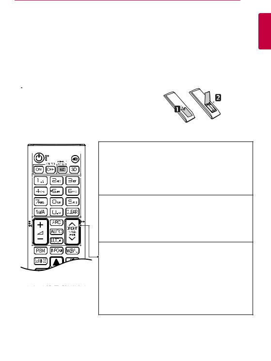
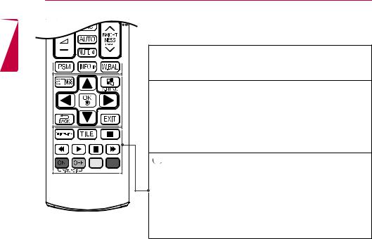
REMOTE CONTROL
The descriptions in this manual are based on the buttons on the remote control. Please read this manual carefully to use the monitor correctly.
To install batteries, open the battery cover, place batteries (1.5 V AAA) matching  and
and  terminals to the labels inside the compartment, and close the battery cover.
To remove the batteries, perform the installation actions in reverse. The illustrations may differ from the actual accessories.
 CAUTION
•• Do not mix old and new batteries, as this may damage the remote control.
•• Be sure to point the remote control toward the remote control sensor on the monitor.
 (POWER) Turns the monitor on or off.


 MONITOR ON Turns the monitor on.
MONITOR OFF Turns the monitor off.
ENERGY SAVING( ) Reduces power consumption by adjusting peak
screen brightness.
INPUT Selects the input mode.
3D Used for viewing 3D videos. (This model does not support this.)

 1/a/A Toggles between numerical and alphabetical.
(Depending upon the model, this feature may not be supported.)
Number and Alphabet buttons
Enters numerical or alphabetical characters depending upon the setting.
(Depending upon the model, this feature may not be supported.)
CLEAR Deletes the entered numerical or alphabetical character. (Depending upon the model, this feature may not be supported.)
Volume Up/Down Button Adjusts the volume.
ARC Selects the Aspect Ratio mode.
AUTO Automatically adjusts picture position and minimizes image instability (available for RGB input only). (Depending upon the
model, this feature may not be supported.) MUTE Mutes all sounds.
BRIGHTNESS Adjust the brightness by pressing the Up and Down buttons on the remote control. In USB mode, the OSD menu has the Page function to move to the next file list. (Depending upon the model, this feature may not be supported.)
ENGLISH
ENGLISH
20 REMOTE CONTROL
PSM Selects the Picture Mode.


 INFO
INFO Views the information of the currently program and the screen. W.BAL Enters the White Balance menu.
SETTINGS Accesses the main menus or saves your input and exit menus.

 S.MENU SuperSign menu key (Depending upon the model, this feature
may not be supported.)
Navigation Buttons Scrolls through menus or options.
OK Selects menus or options and confirms your input.
BACK Allows you to move back one step in the user interaction function. EXIT Quit all OSD tasks and applications.


 Allows you to control various multimedia devices to enjoy multimedia simply by using the remote control through the SimpLink menu. (Depending upon the model, this feature
may not be supported.) TILE Selects the TILE Mode.
PICTURE ID ON/OFF When the Picture ID number matches the Set ID number, you can control whichever monitor you want in multi-display format.
USB Menu Control Buttons Controls media playback.
REMOTE CONTROL 21
Displaying the Device Name Connected to an Input Port
Display which devices are connected to which external input ports.
1Access the Input list screen and press the red (input label) button on the remote control.
2You can assign an input label for every input except USB.
 NOTE
NOTE
•• External inputs supported : HDMI, DVI-D
•• Labels available : PC, DTV
•• The input labels are displayed on the Input Label screen or at the top left of the screen when you change the external input setting.
•• For DTV/PC-compatible signals, such as 1080p 60 Hz, the screen settings may change according to the input label. The Just Scan option is available if a PC is connected as an external device.
White Balance Adjust Menu
Press the W.BAL button on the remote control.
yyR-Gain : Adjusts the level of red. The higher
the number, the redder the set. Decrease the number if the screen looks too red.
yyG-Gain : Adjusts the level of green. The
higher the number, the greener the set. Decrease the number if the screen looks too green.
yyB-Gain : Adjusts the level of blue. The higher
the number, the bluer the set. Decrease the number if the screen looks too blue.
yyBacklight : Adjusts the brightness. The
higher the number, the brighter the set. This works in the same way as the backlight of the user menu.
yyReset : Resets the white balance value to the factory settings.
ENGLISH
ENGLISH
22 REMOTE CONTROL
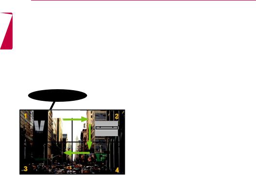
Using Picture ID
Picture ID is used to change the settings of a specific display using a single IR receiver for multi-vision. The set receiving the IR signal communicates with another set via an RS-232C connection. Each set is identified by a Set ID. If you assign the Picture ID using the remote control, only displays with the same Picture ID and Set ID can be controlled remotely.
IR Receiver
RS-232C
Picture ID
Off
Close
2X2 Multi-Vision
Set IDs are assigned as shown in the picture.
1Press the red ON button on the remote control to assign the Picture ID.
2To change the Picture ID, press the ON button, or the left and right arrow buttons continuously. Assign the ID you want.
•• If you assign the Set ID to each set with multivision, and then assign the Picture ID using the red button on the remote control, the key
command is displayed for the set with the same Set ID and Picture ID. A set with different Set IDs and Picture IDs cannot be controlled by IR signals.
 NOTE
NOTE
•• For example, if the Picture ID is assigned to 2, the upper right display (Set ID: 2) can be controlled by IR signals.
•• For each set, you can change the settings for the PICTURE, AUDIO, TIME, NETWORK and MY MEDIA menus or the hot keys on the remote control.
•• If you press the green OFF button for Picture IDs, the Picture IDs for all sets are turned off. If you then press any button on the remote control, all sets will start working again.
•• Picture ID will be disabled while using the MY MEDIA menu.
MAKING CONNECTIONS 23
MAKING CONNECTIONS
You can connect various external devices to your monitor. Change the input mode and select the external device you want to connect.
For more information about external device connections, see the user manual provided with each device.
Connecting to a PC
The illustrations may differ from the actual accessories. Some of the cables are not provided. This monitor supports the Plug & Play* feature.
* Plug & Play: a feature that enables a PC to recognize devices attached by the user without device configuration or user intervention when powering up.
32/43/49/55SE3* 43/49/55SL5B
Mac |
IN |
|
RGB |
|
AUDIO OUT |
RGB OUT |
|
IN |
|
|
|
|
|
|
DVI-D |
|
|
|
(not included) |
|
|
|
|
|
SPEAKER |
RS-232C RS-232C |
EXT IR |
AUDIO |
AUDIO |
|
|
OUT |
IN |
OUT |
IN |
IN |
OUT |
(not included) |
|
|
|
|
|
|
|
(Only for **SE3B/ **SL5B model)
ENGLISH
HDMI OU |
(not included) |
|
|
|
AUDIO OUT |
DVI OUT |
|
|
|
(not included)
24 MAKING CONNECTIONS
65SE3*
ENGLISH
LAN
(not included)
(not included)
Mac
HDMI OUT
RGB IN
DVI OUT |
AUDIO OUT |
RGB OUT |
(not included)
DVI-D IN
(not included)
SPEAKER |
RS-232C RS-232C |
EXT IR |
AUDIO |
AUDIO |
|
OUT |
IN |
OUT |
IN |
IN |
OUT |
(Only for **SE3B model)
AUDIO OUT |
DVI OUT |

MAKING CONNECTIONS 25
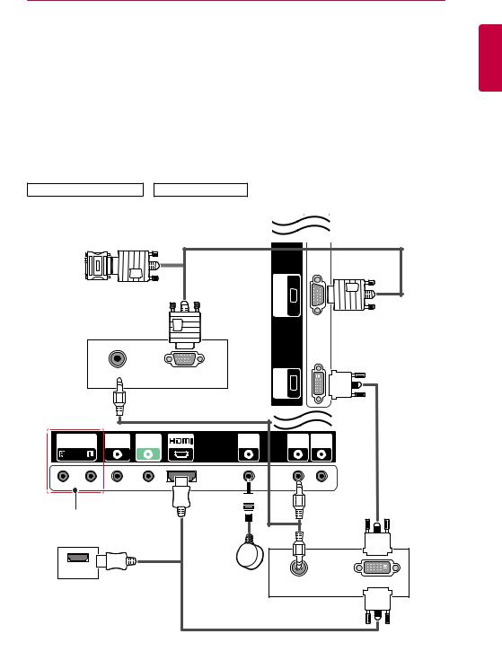
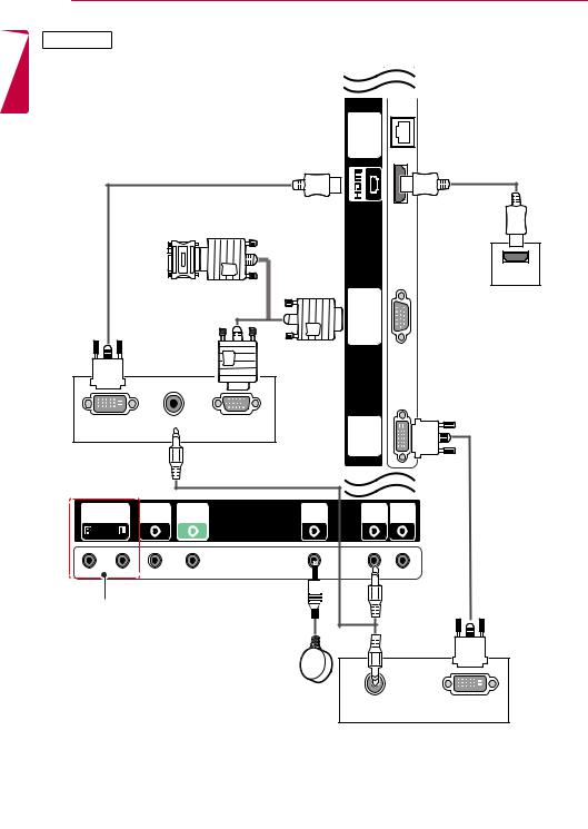
External Device Connection
Connect a HD receiver, DVD, or VCR player to the monitor and select an appropriate input mode.
The illustrations may differ from the actual accessories. Some of the cables are not provided. For the best picture and sound quality, connecting external devices to your monitor using HDMI cables is recommended.
32/43/49/55SE3* 43/49/55SL5B
USB 2 5 V 1.0 A
|
03OR |
A |
USB |
USB1 V 1.0 |
(not included) |
|
|
5 |
|
|
|
|
|
LAN |
(not included) |
|
|
|
|
|
|
|
|
|
|
|
Direct Connection/ |
|
|
|
|
|
Using the Router/ |
|
|
|
|
|
Using the Internet |
|
|
HDMI OUT |
|
IN |
|
|
|
|
RGB |
|
|
|
|
|
|
|
|
HD Receiver/DVD/VCR |
|
|
|
||
Camcorder/Camera/Gaming Device |
|
|
|
||
|
|
|
|
DVI-D IN |
|
|
|
|
|
|
Network |
SPEAKER |
RS-232C RS-232C |
EXT IR |
AUDIO |
AUDIO |
|
OUT |
IN |
OUT |
IN |
IN |
OUT |
|
|
|
|
|
AV Receiver |
(Only for **SE3B/ **SL5B model) |
|
|
|
||
|
|
(not included) |
|
|
|
ENGLISH
(not included)

26 MAKING CONNECTIONS
65SE3*
ENGLISH
LAN 5 V 1.0 A 5 V 1.0 A
USB 1 USB 2
(not included)
03OR
USB
(not included)
(not included)
HDMI OUT
RGB IN
HD Receiver/DVD/VCR
Camcorder/Camera/Gaming Device
DVI-D IN
SPEAKER |
RS-232C RS-232C |
EXT IR |
AUDIO |
AUDIO |
|
OUT |
IN |
OUT |
IN |
IN |
OUT |
Network
Direct Connection/
Using the Router/
Using the Internet
(Only for **SE3B model)
AV Receiver |
(not included) |
|
Loading...