


|
|
Internal Use Only |
|
|
|
aNorth/Latin America |
http://aic.lgservice.com |
|
Europe/Africa |
http://eic.lgservice.com |
|
Asia/Oceania |
http://biz.lgservice.com |
|
PLASMA TV
SERVICE MANUAL
CHASSIS : PP78C
MODEL : 32PC51 32PC51-ZB
CAUTION
BEFORE SERVICING THE CHASSIS,
READ THE SAFETY PRECAUTIONS IN THIS MANUAL.
CONTENTS
CONTENTS .............................................................................................. |
2 |
SAFETY PRECAUTIONS .......................................................................... |
3 |
SPECIFICATION ........................................................................................ |
4 |
ADJUSTMENT INSTRUCTION ................................................................. |
6 |
TROUBLE SHOOTING ............................................................................ |
13 |
BLOCK DIAGRAM................................................................................... |
20 |
EXPLODED VIEW .................................................................................. |
22 |
SVC. SHEET ............................................................................................... |
|
PRINTED CIRCUIT DIAGRAM .................................................................... |
|
Copyright©2008 LG Electronics. Inc. All right reserved. |
- 2 - |
LGE Internal Use Only |
Only for training and service purposes |
|
|

SAFETY PRECAUTIONS
IMPORTANT SAFETY NOTICE
Many electrical and mechanical parts in this chassis have special safety-related characteristics. These parts are identified by  in the Schematic Diagram and Exploded View.
It is essential that these special safety parts should be replaced with the same components as recommended in this manual to prevent X-RADIATION, Shock, Fire, or other Hazards.
Do not modify the original design without permission of manufacturer.
General Guidance |
Leakage Current Hot Check (See below Figure) |
|
Plug the AC cord directly into the AC outlet. |
An isolation Transformer should always be used during the servicing of a receiver whose chassis is not isolated from the AC power line. Use a transformer of adequate power rating as this protects the technician from accidents resulting in personal injury from electrical shocks.
It will also protect the receiver and it's components from being damaged by accidental shorts of the circuitry that may be inadvertently introduced during the service operation.
If any fuse (or Fusible Resistor) in this monitor is blown, replace it with the specified.
When replacing a high wattage resistor (Oxide Metal Film Resistor, over 1W), keep the resistor 10mm away from PCB.
Do not use a line Isolation Transformer during this check.
Connect 1.5K/10watt resistor in parallel with a 0.15uF capacitor between a known good earth ground (Water Pipe, Conduit, etc.) and the exposed metallic parts.
Measure the AC voltage across the resistor using AC voltmeter with 1000 ohms/volt or more sensitivity.
Reverse plug the AC cord into the AC outlet and repeat AC voltage measurements for each exposed metallic part. Any voltage measured must not exceed 0.75 volt RMS which is corresponds to 0.5mA.
In case any measurement is out of the limits specified, there is possibility of shock hazard and the set must be checked and repaired before it is returned to the customer.
Keep wires away from high voltage or high temperature parts.
Due to high vacuum and large surface area of picture tube, extreme care should be used in handling the Picture Tube.
Do not lift the Picture tube by it's Neck.
Leakage Current Cold Check(Antenna Cold Check)
With the instrument AC plug removed from AC source, connect an electrical jumper across the two AC plug prongs. Place the AC switch in the on position, connect one lead of ohm-meter to the AC plug prongs tied together and touch other ohm-meter lead in turn to each exposed metallic parts such as antenna terminals, phone jacks, etc.
If the exposed metallic part has a return path to the chassis, the measured resistance should be between 1MΩ and 5.2MΩ .
When the exposed metal has no return path to the chassis the reading must be infinite.
An other abnormality exists that must be corrected before the receiver is returned to the customer.
Leakage Current Hot Check circuit
AC Volt-meter
|
|
|
|
Good Earth Ground |
|
|
|
|
|
such as WATER PIPE, |
|
To Instrument’s |
|
|
|
CONDUIT etc. |
|
|
|
|
|||
0.15uF |
|||||
exposed |
|||||
|
|
|
|
||
METALLIC PARTS |
|
|
|
|
|
|
|
|
|
||
1.5 Kohm/10W
Copyright©2008 LG Electronics. Inc. All right reserved. |
- 3 - |
LGE Internal Use Only |
Only for training and service purposes |
|
|

SPECIFICATIONS
NOTE : Specifications and others are subject to change without notice for improvement.
V Application Range
This spec is applied to the 32” PLASMA TV used PP78C Chassis.
Chassis |
Model Name |
Market |
Brand |
Remark |
|
|
|
|
|
PP78C |
32PC51-ZB |
EU |
LG |
ITOLess Model |
|
|
|
|
|
V Specification
Each part is tested as below without special appointment.
1)Temperature : 25±5°C (77±9°F), CST : 40±5
2)Relative Humidity: 65±10%
3)Power Voltage: Standard Input voltage (100-240V~, 50/60Hz)
*Standard Voltage of each product is marked by models.
4)Specification and performance of each parts are followed each drawing and specification by part number in accordance with SBOM.
5)The receiver must be operated for about 20 minutes prior to the adjustment.
VTest Method
1)Performance : LGE TV test method followed.
2)Demanded other specification
Safety : CE, IEC specification
EMC : CE, IEC
Model |
Market |
Appliance |
Remark |
|
|
|
|
32PC51-ZB |
EU |
Safety : IEC/EN60065, |
ITOLess Model |
|
|
EMI : EN55013, |
|
|
|
EMS : EN55020 |
|
|
|
|
|
V General Specification ( 32”WVGA )
No |
Item |
|
Specification |
Remark |
|
|
|
|
|
1 |
Display Screen Device |
32” Wide Color Display Module |
Plasma Display Panel |
|
|
|
|
|
|
2 |
Aspect Ratio |
16:9 |
|
|
|
|
|
|
|
3 |
PDP Module |
PDP32F1, |
|
Glass Filter |
|
|
RGB Closed Type |
|
|
|
|
|
|
|
4 |
Operating Environment |
1)Temp. |
: 0~40deg |
LGE SPEC. |
|
|
2)Humidity : 0~85% |
|
|
|
|
|
|
|
5 |
Storage Environment |
3)Temp. |
: -20~60deg |
|
|
|
4)Humidity : 0~85% |
|
|
|
|
|
|
|
6 |
Input Voltage |
100-240V~, 50/60Hz |
Maker : LG |
|
|
|
|
|
|
Copyright©2008 LG Electronics. Inc. All right reserved. |
- 4 - |
LGE Internal Use Only |
Only for training and service purposes |
|
|

V General Specification2
No |
Item |
|
Specification |
|
Remark |
|
|
|
|
|
|
|
|
1 |
Market |
EU |
|
|
|
|
|
|
|
|
|
|
|
2 |
Broadcasting system |
PAL-BG/I/DK, SECAM |
|
|
||
|
|
|
|
|
|
|
3 |
Available Channel |
BAND |
PAL |
|
NTSC |
|
|
|
|
|
|
|
|
|
|
VHF/UHF |
C1~C69 |
|
2~83 |
|
|
|
CATV |
S1~S47 |
|
1~71 |
|
|
|
|
|
|
|
|
4 |
Receiving system |
Upper Heterodyne |
|
|
||
|
|
|
|
|
|
|
5 |
SCART Jack(2EA) |
PAL, SECAM, NTSC |
|
Full SCART, Half SCART |
||
|
|
|
|
|
|
|
6 |
Component Input (1EA) |
Y/Cb/Cr, Y/Pb/Pr |
|
|
||
|
|
|
|
|
|
|
7 |
RGB Input(1EA) |
RGB-PC |
|
|
|
|
|
|
|
|
|
|
|
8 |
HDMI Input(1EA) |
HDMI-DTV |
|
|
|
HDMI PC spec out |
|
|
|
|
|
|
|
9 |
Audio Input (4EA) |
PC Audio, Component(1EA), |
|
L/R Input |
||
|
|
|
|
|
|
|
10 |
Audio variable out(1EA) |
|
|
|
|
|
|
|
|
|
|
|
|
V Module Specification ( PDP32F1 )
No |
Item |
|
Min |
|
Typ |
Max |
Unit |
Remark |
|
|
|
|
|
|
|
|
|
1 |
Display area |
|
708.0.1(H) x 398.4(V) ± 0.5mm |
mm |
|
|||
|
|
|
|
|
|
|
|
|
2 |
Outline dimension |
|
790(H) x 466.5(V) x 59.1(D) ± 1mm |
mm |
|
|||
|
|
|
|
|
|
|
|
|
3 |
Number of Pixels |
|
852(H) x 480(V) |
|
|
1Pixel=3RGB Cells |
||
|
|
|
|
|
|
|
|
|
4 |
Cell pitch |
|
831um(H) x 830um(V) |
|
um |
1Pixel=3RGB Cells |
||
|
|
|
|
|
|
|
|
|
5 |
Pixel type |
|
RGB closed type |
|
|
|
||
|
|
|
|
|
|
|
|
|
6 |
Weight(net) |
|
7.55 |
|
8.05 |
8.55 |
Kg |
|
|
|
|
|
|
|
|
|
|
7 |
Weight(gross) |
|
118.5 |
|
123.5 |
128.5 |
Kg |
12 1Box |
|
|
|
|
|
|
|
|
|
8 |
Operation Environment |
Temperature |
0 ~ 40 |
|
|
|
deg |
|
|
|
|
|
|
|
|
|
|
|
|
Humidity |
20 ~ 80 |
|
|
|
% |
|
|
|
|
|
|
|
|
|
|
|
|
Pressure |
800 ~ 1100 |
|
|
hPa |
Altitude : 0 to 2000M |
|
|
|
|
|
|
|
|
|
|
9 |
Storage Environment |
Temperature |
-20 ~ 60 |
|
|
|
deg |
|
|
|
|
|
|
|
|
|
|
|
|
Humidity |
10 ~ 90 |
|
|
|
% |
|
|
|
|
|
|
|
|
|
|
|
|
Pressure |
700 ~ 1100 |
|
|
hPa |
Altitude : 0 to 3000M |
|
|
|
|
|
|
|
|
|
|
10 |
I mage stick minimization |
Start time |
4.5 |
|
5 |
5.5 |
min |
|
|
|
|
|
|
|
|
|
|
|
mode |
Low Brightness |
14 |
|
15 |
16 |
min |
|
|
|
Arrival Time |
|
|
|
|
|
|
|
|
|
|
|
|
|
|
|
Copyright©2008 LG Electronics. Inc. All right reserved. |
- 5 - |
LGE Internal Use Only |
Only for training and service purposes |
|
|
ADJUSTMENT INSTRUCTION
1. Application Object
These instructions are applied all of the 32” PLASMA TV,
PP78C Chassis.
2.Note
(1)Because this is not a hot chassis, it is not necessary to use an isolation transformer. However, the use of isolation transformer will help protect test instrument.
(2)Adjustment must be done in the correct order.
(3)The adjustment must be performed in the circumstance of 25±5°C of temperature and 65±10% of relative humidity if there is no specific designation.
(4)The input voltage of the receiver must keep 100-220V~, 50/60Hz.
(5)Before adjustment, execute Heat Run for 30 minutes.
3.Adjustment items
3.1.PCB assembly adjustment items
(1)Download the VCTP main software (IC500,VCT_Pro)
(2)Color carrier Adjustment
3.2.SET assembly adjustment items
(1)DDC Data input.
(2)Adjustment of White Balance.
(3)Factoring Option Data input.
4. PCB assembly adjustment method
(Using VCTP Download program)
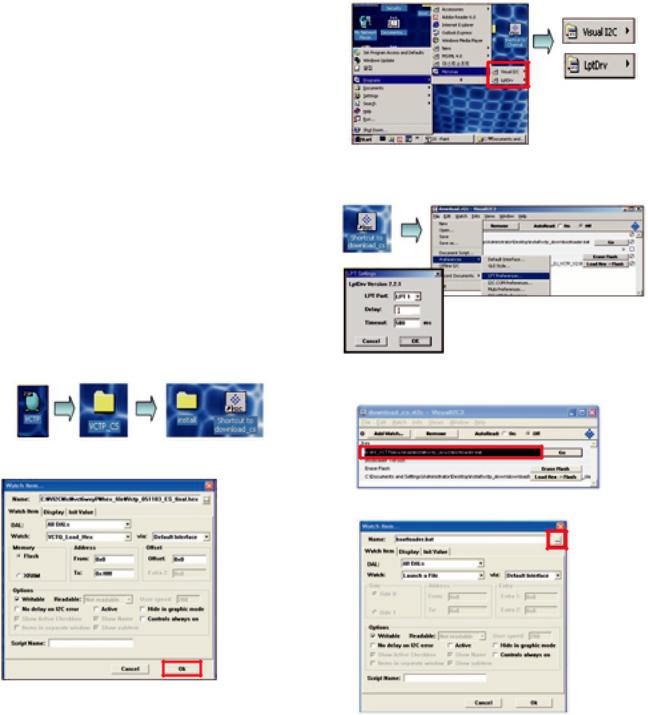
4-1. Download program installation
(1) Extract a Zip file.
(2) Visual I2C & LPT Driver Installation.
Install the LPT Driver
Install the Visual I2C
LPT Port Driver (LptDrv) Setups : Program Files > Micronas > Visual I2C > Port_Driver
*Use for Windows 95/98 : Setup_LptDrv_v0104_9x.exe
*Use for Windows 2000/XP : Setup_LptDrv_v0202_XP_2000.exe *Use for Windows NT : Setup_LptDrv_v0104_NT.exe
(3) Verification.(Start > Programs > Micronas > Visual I2C or LptDrv)
(4) LPT delay setting.(File > Preference > LPT preferences)
*LPT SETTING
-Delay => 1
-Time out => 500 ms
(5)Exchange the “bootloader.bat” file.
G Double click the Red area
Copyright©2008 LG Electronics. Inc. All right reserved. |
- 6 - |
LGE Internal Use Only |
Only for training and service purposes |
|
|
(4) Click the "Erase Flash" button.
(5) Double click the download file low, then "edit" window will be opened.
G Select the "Bootloader.bat" file.
(install > VCTP_download > Bootloader) G Push "OK".
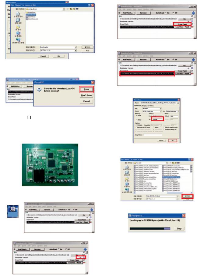
(6) Click the choice button in the “edit window”, then “file choice window” will be opened.
G Finish the program, after saving the file "download_cs.vi2c". (if you click x , the massage appears automatically)
5. S/W program download
5-1. Download method 1 (PCB Ass’y)
(1)Connect the download jig to D-sub jack.
(2)Execute ‘Download.vi2c’ program in PC, then a main window will be opened.
Shortcut to download
Double click
(7) Choose the Hex file in folder and execute downloading with click " open" button.
(8)Click OK button at the "edit window".
(9)Under Downloading process.
(3) Double click the blue box and confirm "Bootloader Version" as 42.
(10) If download is failed, for example "No acknowledge from slave". Execute download again from(1).
Copyright©2008 LG Electronics. Inc. All right reserved. |
- 7 - |
LGE Internal Use Only |
Only for training and service purposes |
|
|

5-2.Download method 2 (Set)
(1) Push the “Tilt” button in an Adjust Remocon Then the PLASMA TV will change a “slave mode”.
(2) Connect Zig to TV using a D-sub cable.
(3) Execute ‘Download_CS.vi2c’ program in PC, then a main widow will be opened.
Shortcut to download_cs
Double click
(4) Click "GO" button.
If you don’t push the “go” , the Hex file would not be downloaded although the download proceeds normally at first glance.
(5) Double click the blue box and confirm "Bootloader Version" as 42.
(6) Click the "Erase Flash" button.
(7) Double click the download file low then, "edit" window will be opened.
(8) Chick the choice button I n the "edit window", then "file choice window’ will be opened.
(9) Click the “load > flash” button.
(10) Click OK button at the "edit window".
(11)Under Downloading progress.
(12)If download is failed, for example "No acknowledge from slave", execute download again from (1).
Copyright©2008 LG Electronics. Inc. All right reserved. |
- 8 - |
LGE Internal Use Only |
Only for training and service purposes |
|
|
 Loading...