


 Loading...
FS-1370DN
SERVICE
MANUAL
Published in June 2010
842L0112
2L0SM062
Rev. 2
CAUTION
RISK OF EXPLOSION IF BATTERY IS REPLACED BY AN INCORRECT TYPE. DISPOSE OF USED BATTERIES ACCORDING TO THE INSTRUCTIONS.
It may be illegal to dispose of this battery into the municipal waste stream. Check with your local solid waste officials for details in your area for proper disposal.
ATTENTION
IL Y A UN RISQUE D’EXPLOSION SI LA BATTERIE EST REMPLACEE PAR UN MODELE DE TYPE INCORRECT. METTRE AU REBUT LES BATTERIES UTILISEES SELON LES INSTRUCTIONS DONNEES.
Il peut être illégal de jeter les batteries dans des eaux d’égout municipales. Vérifiez avec les fonctionnaires municipaux de votre région pour les détails concernant des déchets solides et une mise au rebut appropriée.
Revision history
Revision |
Date |
|
Replaced pages |
Remarks |
|
|
|
|
|
1 |
April 23, 2010 |
1-3-1, 1-3-2, 1-3-7, 1-3-10 to 1-3-14, 1-4-2, 1-4-3, |
- |
|
|
|
1-6-2, |
1-6-6 |
|
|
|
|
|
|
2 |
June 3, 2010 |
1-1-1, |
1-3-1, 1-3-8 |
- |
|
|
|
|
|

This page is intentionally left blank.

Safety precautions
This booklet provides safety warnings and precautions for our service personnel to ensure the safety of their customers, their machines as well as themselves during maintenance activities. Service personnel are advised to read this booklet carefully to familiarize themselves with the warnings and precautions described here before engaging in maintenance activities.

Safety warnings and precautions
Various symbols are used to protect our service personnel and customers from physical danger and to prevent damage to their property. These symbols are described below:
 DANGER: High risk of serious bodily injury or death may result from insufficient attention to or incorrect compliance with warning messages using this symbol.
 WARNING: Serious bodily injury or death may result from insufficient attention to or incorrect compliance with warning messages using this symbol.
 CAUTION: Bodily injury or damage to property may result from insufficient attention to or incorrect compliance with warning messages using this symbol.
Symbols
The triangle ( ) symbol indicates a warning including danger and caution. The specific point of attention is shown inside the symbol.
General warning. |
Warning of risk of electric shock. |
Warning of high temperature.
 indicates a prohibited action. The specific prohibition is shown inside the symbol.
General prohibited action. |
Disassembly prohibited. |
 indicates that action is required. The specific action required is shown inside the symbol.
General action required. |
Remove the power plug from the wall outlet. |
Always ground the copier.

1. Installation Precautions
 WARNING
•Do not use a power supply with a voltage other than that specified. Avoid multiple connections to one outlet: they may cause fire or electric shock. When using an extension cable, always check that it is adequate for the rated current. .....................................................................................................
•Connect the ground wire to a suitable grounding point. Not grounding the copier may cause fire or electric shock. Connecting the earth wire to an object not approved for the purpose may cause explosion or electric shock. Never connect the ground cable to any of the following: gas pipes, lightning rods, ground cables for telephone lines and water pipes or faucets not approved by the proper authorities. ..........................................................................................................................................
 CAUTION:
•Do not place the copier on an infirm or angled surface: the copier may tip over, causing injury. .........
•Do not install the copier in a humid or dusty place. This may cause fire or electric shock. .................
•Do not install the copier near a radiator, heater, other heat source or near flammable material. This may cause fire. ...................................................................................................................................
•Allow sufficient space around the copier to allow the ventilation grills to keep the machine as cool as possible. Insufficient ventilation may cause heat buildup and poor copying performance. ............
•Always handle the machine by the correct locations when moving it. .................................................
•Always use anti-toppling and locking devices on copiers so equipped. Failure to do this may cause the copier to move unexpectedly or topple, leading to injury. ..............................................................
•Avoid inhaling toner or developer excessively. Protect the eyes. If toner or developer is accidentally ingested, drink a lot of water to dilute it in the stomach and obtain medical attention immediately. If it gets into the eyes, rinse immediately with copious amounts of water and obtain medical atten-
tion. .....................................................................................................................................................
•Advice customers that they must always follow the safety warnings and precautions in the copier’s instruction handbook. .........................................................................................................................

2. Precautions for Maintenance
 WARNING
•Always remove the power plug from the wall outlet before starting machine disassembly. ................
•Always follow the procedures for maintenance described in the service manual and other related brochures. ..........................................................................................................................................
•Under no circumstances attempt to bypass or disable safety features including safety mechanisms and protective circuits. ........................................................................................................................
•Always use parts having the correct specifications. ............................................................................
•Always use the thermostat or thermal fuse specified in the service manual or other related brochure when replacing them. Using a piece of wire, for example, could lead to fire or other serious accident. ...................................................................................................................................................
•When the service manual or other serious brochure specifies a distance or gap for installation of a part, always use the correct scale and measure carefully. ..................................................................
•Always check that the copier is correctly connected to an outlet with a ground connection. ...............
•Check that the power cable covering is free of damage. Check that the power plug is dust-free. If it is dirty, clean it to remove the risk of fire or electric shock. .................................................................
•Never attempt to disassemble the optical unit in machines using lasers. Leaking laser light may damage eyesight. ...............................................................................................................................
•Handle the charger sections with care. They are charged to high potentials and may cause electric shock if handled improperly. ...............................................................................................................
 CAUTION
•Wear safe clothing. If wearing loose clothing or accessories such as ties, make sure they are safely secured so they will not be caught in rotating sections. ......................................................................
•Use utmost caution when working on a powered machine. Keep away from chains and belts. ..........
•Handle the fixing section with care to avoid burns as it can be extremely hot. ..................................
•Check that the fixing unit thermistor, heat and press rollers are clean. Dirt on them can cause abnormally high temperatures. ...........................................................................................................

•Do not remove the ozone filter, if any, from the copier except for routine replacement. ......................
•Do not pull on the AC power cord or connector wires on high-voltage components when removing them; always hold the plug itself. ........................................................................................................
•Do not route the power cable where it may be stood on or trapped. If necessary, protect it with a cable cover or other appropriate item. ................................................................................................
•Treat the ends of the wire carefully when installing a new charger wire to avoid electric leaks. ..........
•Remove toner completely from electronic components. .....................................................................
•Run wire harnesses carefully so that wires will not be trapped or damaged. ......................................
•After maintenance, always check that all the parts, screws, connectors and wires that were removed, have been refitted correctly. Special attention should be paid to any forgotten connector, trapped wire and missing screws. .......................................................................................................
•Check that all the caution labels that should be present on the machine according to the instruction handbook are clean and not peeling. Replace with new ones if necessary. .......................................
•Handle greases and solvents with care by following the instructions below: ......................................
·Use only a small amount of solvent at a time, being careful not to spill. Wipe spills off completely.
·Ventilate the room well while using grease or solvents.
·Allow applied solvents to evaporate completely before refitting the covers or turning the power switch on.
·Always wash hands afterwards.
•Never dispose of toner or toner bottles in fire. Toner may cause sparks when exposed directly to fire in a furnace, etc. ...........................................................................................................................
•Should smoke be seen coming from the copier, remove the power plug from the wall outlet immediately. ...................................................................................................................................................
3. Miscellaneous
 WARNING
•Never attempt to heat the drum or expose it to any organic solvents such as alcohol, other than the specified refiner; it may generate toxic gas. ........................................................................................

This page is intentionally left blank.
|
|
|
2L0 |
|
|
CONTENTS |
|
1-1 Specifications |
|
||
1-1-1 Specifications.......................................................................................................................................... |
1-1-1 |
||
1-1-2 |
Parts names............................................................................................................................................ |
1-1-3 |
|
|
(1) |
Overall ............................................................................................................................................... |
1-1-3 |
|
(2) |
Operation panel................................................................................................................................. |
1-1-4 |
1-1-3 |
Machine cross section ............................................................................................................................ |
1-1-5 |
|
1-2 Installation |
|
||
1-2-1 |
Installation environment .......................................................................................................................... |
1-2-1 |
|
1-2-2 Unpacking ............................................................................................................................................... |
1-2-2 |
||
|
(1) |
Removing the tapes .......................................................................................................................... |
1-2-3 |
1-2-3 Installing the expanded memory (option)................................................................................................ |
1-2-4 |
||
1-2-4 Installing the memory card (optional)...................................................................................................... |
1-2-5 |
||
1-3 Maintenance Mode |
|
||
1-3-1 |
Service mode .......................................................................................................................................... |
1-3-1 |
|
|
(1) |
Executing a service item ................................................................................................................... |
1-3-1 |
|
(2) |
Contents of service mode items ........................................................................................................ |
1-3-2 |
|
(3) |
Printing an event log (EVENT LOG)................................................................................................ |
1-3-10 |
1-4 Troubleshooting |
|
||
1-4-1 |
Paper misfeed detection ......................................................................................................................... |
1-4-1 |
|
|
(1) |
Paper misfeed indication ................................................................................................................... |
1-4-1 |
|
(2) |
Paper misfeed detection condition .................................................................................................... |
1-4-1 |
1-4-2 |
Self-diagnostic function........................................................................................................................... |
1-4-2 |
|
|
(1) |
Self-diagnostic function ..................................................................................................................... |
1-4-2 |
|
(2) |
Self diagnostic codes ........................................................................................................................ |
1-4-3 |
1-4-3 |
Image formation problems ...................................................................................................................... |
1-4-7 |
|
|
(1) |
Completely blank printout.................................................................................................................. |
1-4-8 |
|
(2) |
All-black printout................................................................................................................................ |
1-4-8 |
|
(3) |
Dropouts............................................................................................................................................ |
1-4-9 |
|
(4) |
Black dots.......................................................................................................................................... |
1-4-9 |
|
(5) |
Black horizontal streaks. ................................................................................................................... |
1-4-9 |
|
(6) |
Black vertical streaks....................................................................................................................... |
1-4-10 |
|
(7) |
Unsharpness. .................................................................................................................................. |
1-4-10 |
|
(8) |
Gray background............................................................................................................................. |
1-4-10 |
|
(9) |
Dirt on the top edge or back of the paper........................................................................................ |
1-4-11 |
|
(10) |
Undulated printing at the right edge (scanning start position)......................................................... |
1-4-11 |
1-4-4 |
Electric problems .................................................................................................................................. |
1-4-12 |
|
1-4-5 |
Mechanical problems ............................................................................................................................ |
1-4-14 |
|
1-5 Assembly and Disassembly |
|
||
1-5-1 Precautions for assembly and disassembly............................................................................................ |
1-5-1 |
||
|
(1) |
Precautions ....................................................................................................................................... |
1-5-1 |
|
(2) |
Drum.................................................................................................................................................. |
1-5-1 |
|
(3) |
Toner container ................................................................................................................................. |
1-5-1 |
|
(4) |
How to tell a genuine Kyocera Mita toner container.......................................................................... |
1-5-2 |
1-5-2 |
Outer covers ........................................................................................................................................... |
1-5-3 |
|
|
(1) |
Detaching and refitting the top cover................................................................................................. |
1-5-3 |
|
(2) |
Detaching and refitting the right and left covers ................................................................................ |
1-5-4 |
1-5-3 |
Paper feed section .................................................................................................................................. |
1-5-6 |
|
|
(1) |
Detaching and refitting the paper feed roller assembly (paper feed roller and pickup roller) ............ |
1-5-6 |
|
(2) |
Detaching and refitting the retard roller assembly............................................................................. |
1-5-8 |
|
(3) |
Detaching and refitting the MP paper feed roller............................................................................. |
1-5-10 |
1-5-4 |
Developing section................................................................................................................................ |
1-5-11 |
|
|
(1) |
Detaching and refitting the developing unit ..................................................................................... |
1-5-11 |
1-5-5 |
Drum section......................................................................................................................................... |
1-5-12 |
|
|
(1) |
Detaching and refitting the drum unit .............................................................................................. |
1-5-12 |
|
(2) |
Detaching and refitting the main charger unit.................................................................................. |
1-5-13 |
2L0
1-5-6 |
Transfer/separation section .................................................................................................................. |
1-5-14 |
|
|
(1) |
Detaching and refitting the transfer roller ........................................................................................ |
1-5-14 |
1-5-7 |
Fuser section ........................................................................................................................................ |
1-5-16 |
|
|
(1) |
Detaching and refitting the fuser unit............................................................................................... |
1-5-16 |
|
(2) |
Switching the fuser pressure ........................................................................................................... |
1-5-18 |
1-5-8 |
PWBs .................................................................................................................................................... |
1-5-19 |
|
|
(1) |
Detaching and refitting the control PWB ......................................................................................... |
1-5-19 |
|
(2) |
Detaching and refitting the power source PWB............................................................................... |
1-5-22 |
|
(3) |
Detaching and refitting the high voltage PWB................................................................................. |
1-5-24 |
1-5-9 |
Others ................................................................................................................................................... |
1-5-28 |
|
|
(1) |
Detaching and refitting the main motor ........................................................................................... |
1-5-28 |
|
(2) |
Detaching and refitting the laser scanner unit ................................................................................. |
1-5-29 |
|
(3) |
Detaching and refitting the eraser lamp (PWB)............................................................................... |
1-5-31 |
|
(4) |
Direction of installing the left cooling fan motor and right cooling fan motor ................................... |
1-5-32 |
1-6 Firmware
1-6-1 Downloading firmware ............................................................................................................................ |
1-6-1 |
|
(1) |
Firmware files .................................................................................................................................... |
1-6-1 |
(2) |
Downloading the firmware from the USB memory ............................................................................ |
1-6-2 |
(3) |
Downloading the firmware from the memory card............................................................................. |
1-6-4 |
2-1 Mechanical Construction
2-1-1 |
Paper feed/conveying section................................................................................................................. |
2-1-1 |
|
|
(1) |
Cassette paper feed section.............................................................................................................. |
2-1-1 |
|
(2) |
MP tray paper feed section ............................................................................................................... |
2-1-2 |
|
(3) |
Paper conveying section ................................................................................................................... |
2-1-3 |
2-1-2 |
Drum section........................................................................................................................................... |
2-1-4 |
|
|
(1) |
Drum section ..................................................................................................................................... |
2-1-4 |
|
(2) |
Main charger unit............................................................................................................................... |
2-1-5 |
2-1-3 |
Optical section ........................................................................................................................................ |
2-1-6 |
|
|
(1) |
Laser scanner unit............................................................................................................................. |
2-1-6 |
2-1-4 |
Developing section.................................................................................................................................. |
2-1-8 |
|
2-1-5 |
Transfer/separation section .................................................................................................................... |
2-1-9 |
|
2-1-6 |
Cleaning section ................................................................................................................................... |
2-1-10 |
|
2-1-7 |
Fuser section ........................................................................................................................................ |
2-1-11 |
|
2-1-8 |
Paper exit section ................................................................................................................................. |
2-1-13 |
|
2-1-9 |
Duplex/conveying section ..................................................................................................................... |
2-1-15 |
|
2-2 Electrical Parts Layout |
|
|
2-2-1 Electrical parts layout.............................................................................................................................. |
2-2-1 |
|
(1) |
PWBs ................................................................................................................................................ |
2-2-1 |
(2) |
Switches and sensors ....................................................................................................................... |
2-2-3 |
(3) |
Other electrical components.............................................................................................................. |
2-2-4 |
2-3 |
Operation of the PWBs |
|
||
|
2-3-1 |
Power source PWB................................................................................................................................. |
2-3-1 |
|
|
2-3-2 |
Control PWB ........................................................................................................................................... |
2-3-3 |
|
2-4 |
Appendixes |
|
||
|
2-4-1 |
Appendixes ............................................................................................................................................. |
2-4-1 |
|
|
|
(1) |
Wiring diagram .................................................................................................................................. |
2-4-1 |
|
|
(2) |
Repetitive defects gauge................................................................................................................... |
2-4-2 |
|
|
(3) |
Maintenance parts list ....................................................................................................................... |
2-4-3 |
2L0-2
1-1-1 Specifications
Type ................................................ |
Desktop |
Printing method............................... |
Electrophotography, laser scan |
Paper weight................................... |
Cassette: 60 to 120 g/m2 (Duplex: 60 to 105 g/m2) |
|
MP tray: 60 to 220 g/m2 |
Paper type ...................................... |
Cassette: |
|
Plain, Preprinted, Bond, Recycled, Rough, Letterhead, Color (Colour), |
|
Prepunched, High quality, Custom 1 to 8 |
|
MP tray: |
|
Plain, Transparency, Preprinted, Labels, Bond, Recycled, Rough, Vellum, |
|
Letterhead, Color (Colour), Prepunched, Envelope, Cardstock, Thick paper, |
|
High quality, Custom 1 to 8 |
Paper size....................................... |
Cassette: |
|
A4, JIS B5, A5, Folio, Legal, Letter, Oficio II, Statement, Executive, A6, B6, |
|
ISO B5, Envelope C5, 16K, |
|
Custom (105 148 to 216 356 mm/4 1/8 5 13/16" to 8 1/2 14") |
|
MP tray: |
|
A4, JIS B5, A5, Folio, Legal, Letter, Oficio II, Statement, Executive, A6, B6, |
|
ISO B5, Envelope C5, Envelope #10, Envelope #9, Envelope #6-3/4, |
|
Envelope Monarch, Envelope DL, Hagaki, Ofuku Hagaki, 16K, Yokei 2, Yokei 4, |
|
Custom (70 148 to 216 356 mm/2 13/16 5 13/16" to 8 1/2 14") |
Printing speed................................. |
Simplex printing: |
|
35 ppm (A4) |
|
37 ppm (Letter) |
|
17 ppm (A5) |
|
Duplex printing |
|
19 ppm (A4) |
|
20 ppm (Letter) |
First print time ................................. |
7 seconds or less (A4, feed from cassette) |
Warm-up time ................................. |
120 V AC model: |
|
Power on 20 seconds or less (22 C/71.6 F, 60%RH) |
|
Sleep 15 seconds or less (22 C/71.6 F, 60%RH) |
|
220 - 240 V AC model: |
|
Power on 19 seconds or less (22 C/71.6 F, 60%RH) |
|
Sleep 14 seconds or less (22 C/71.6 F, 60%RH) |
Paper capacity ................................ |
Cassette: 250 sheets (80 g/m2, A4/Letter or smaller) |
|
MP tray: 50 sheets (80 g/m2, A4/Letter or smaller) |
Output tray capacity........................ |
Simplex printing: 250 sheets (80 g/m2) |
|
Duplex printing: 200 sheets (80 g/m2) |
Continuous printing......................... |
1 to 999 sheets |
Photoconductor............................... |
OPC drum (diameter 30 mm) |
Image write system......................... |
Semiconductor laser (1 beam) |
Charging system............................. |
Scorotron (positive charging) |
Developing system ......................... |
Mono component dry developing method |
|
Toner replenishing: Automatic from the toner container |
Transfer system .............................. |
Transfer roller (negative-charged) |
Separation system .......................... |
Small diameter separation, discharger brush |
Cleaning system ............................. |
Drum: Counter blade |
Charge erasing system................... |
Exposure by eraser lamp (LED) |
Fusing system................................. |
Heat roller system |
Memory........................................... |
Standard: 128 MB |
|
Maximum: 1152 MB |
Resolution....................................... |
Fine 1200 mode, Fast 1200 mode, 600 dpi, 300 dpi |
Operating environment ................... |
Temperature: 10 to 32.5 C/50 to 90.5 F |
|
Humidity: 15 to 80% |
|
Altitude: 2,500 m/8,202 ft maximum |
|
Brightness: 1,500 lux maximum |
1-1-1
2L0 |
|
Controller ........................................ |
PowerPC 440F5/500 MHz |
Supported OS ................................. |
Microsoft Windows 2000/XP/Vista/7, Windows Server 2003/2008, |
|
Mac OS X 10.x |
Interface.......................................... |
Hi-Speed USB: 1 |
|
Network: 1 (10BASE-T/100BASE-TX) |
|
KUIO-W slot: 1 |
PDL................................................. |
PRESCRIBE |
Dimension (W D H)................... |
375 393 267 mm |
|
14 3/4 15 1/2 10 1/2" |
Weight (without toner container) ..... |
12 kg/26.5 lb |
Power source.................................. |
120 V AC, 60 Hz, 8.0 A |
|
220 to 240 V AC, 50/60 Hz, 4.2 A |
Power consumption ........................ |
120 V AC model, Standard |
|
Maximum: 925 W |
|
During printing: 584.0 W |
|
During standby: 10.3 W (EcoFuser ON), 93.3 W (EcoFuser OFF) |
|
Sleep mode: 5.5 W |
|
120 V AC model, Full options |
|
Maximum: 935 W |
|
During printing: 593.1 W |
|
During standby: 12.9 W (EcoFuser ON), 89.1 W (EcoFuser OFF) |
|
Sleep mode: 6.8 W |
|
220 - 240 V AC model, Standard |
|
Maximum: 987 W |
|
During printing: 553.9 W |
|
During standby: 11.0 W (EcoFuser ON), 89.3 W (EcoFuser OFF) |
|
Sleep mode: 5.5 W |
|
220 - 240 V AC model, Full options |
|
Maximum: 998 W |
|
During printing: 561.9 W |
|
During standby: 13.5 W (EcoFuser ON), 88.2 W (EcoFuser OFF) |
|
Sleep mode: 6.9 W |
Options ........................................... |
Expanded memory, Paper feeder 2 |
NOTE: These specifications are subject to change without notice.
1-1-2

2L0
1-1-2 Parts names
(1) Overall
3
|
2 |
|
|
|
|
|
|
4 |
|
1 |
8 |
|
|
|
|
|
|
10 |
|
|
|
|
16 |
|
|
|
|
12 |
|
|
|
|
11 |
|
7 |
|
|
|
|
|
|
|
5 |
|
|
9 |
|
|
|
|
|
|
13 |
|
|
6 |
|
|
15 |
|
|
|
14 |
|
|
|
|
|
|
|
|
|
Figure 1-1-1 |
|
|
1. |
Top cover |
9. |
Sub tray |
|
2. |
Paper stopper |
10. |
Optional interface slot cover |
|
3. |
Top tray |
11. |
USB interface connector |
|
4. |
Operation panel |
12. |
Network interface connector |
|
5. |
Right side cover |
13. |
Rear cover |
|
6. |
Cassette |
14. |
Power cord connector |
|
7. |
Front cover |
15. |
Power switch |
|
8. |
MP tray |
16. |
USB memory slot |
1-1-3

2L0
(2) Operation panel
|
1 |
2 |
3 |
|
|
|
4 |
9 |
|
|
5 |
5 |
|
|
5 |
8 |
|
|
5 |
7 |
|
|
6 |
|
Figure 1-1-2 |
||
1. |
Ready indicator |
|
|
2. |
Data indicator |
|
|
3. |
Attention indicator |
|
|
4. |
Message display |
|
|
5. |
Cursor keys |
|
|
6. |
GO key |
|
|
7. |
CANCEL key |
|
|
8. |
OK key |
|
|
9. |
MENU key |
|
|
1-1-4

2L0
1-1-3 |
Machine cross section |
|
|
|
|
|
|
|
11 |
12 |
8 |
7 |
6 |
5 |
4 |
|
|
|
|
|
|
|
2 |
10 |
13 |
9 |
1 |
3 |
Light path |
Paper path |
|
Paper path |
|
|
||||
|
|
|
|
(option) |
|
|
Figure 1-1-3 |
|
|
1. |
Cassette |
7. |
Drum unit |
|
2. |
MP tray |
8. |
Laser scanner unit |
|
3. |
Paper feed/conveying |
9. |
Transfer/separation section |
|
|
section |
10. |
Fuser section |
|
4. |
Toner container |
11. |
Paper exit section |
|
5. |
Developing unit |
12. |
Top tray |
|
6. |
Main charger unit |
13. |
Duplex/conveying section |
|
1-1-5

2L0
This page is intentionally left blank.
1-1-6

2L0
1-2-1 Installation environment
1.Temperature: 10 to 32.5 C/50 to 90.5 F
2.Humidity: 15 to 80%RH
3.Power supply: 120 V AC, 8.0 A 220 - 240 V AC, 4.2 A
4.Power source frequency: 50 Hz 0.3%/60 Hz 0.3%
5.Installation location
Avoid direct sunlight or bright lighting. Ensure that the photoconductor will not be exposed to direct sunlight or other strong light when removing paper jams.
Avoid locations subject to high temperature and high humidity or low temperature and low humidity; an abrupt change in the environmental temperature; and cool or hot, direct air.
Avoid places subject to dust and vibrations.
Choose a surface capable of supporting the weight of the machine.
Place the machine on a level surface (maximum allowance inclination: 1 ).
Avoid air-borne substances that may adversely affect the machine or degrade the photoconductor, such as mercury, acidic of alkaline vapors, inorganic gasses, NOx, SOx gases and chlorine-based organic solvents.
Select a well-ventilated location.
6.Allow sufficient access for proper operation and maintenance of the machine.
Machine front: 500 mm/19 11/16"
Machine rear: 200 mm/7 7/8"
Machine right: 300 mm/11 13/16"
Machine left: 300 mm/11 13/16"
Machine top: 200 mm/7 7/8"
|
|
200 mm |
|
|
|
7 7/8" |
|
300 mm |
300 mm |
200 mm |
500 mm |
11 13/16" |
11 13/16" |
7 7/8" |
19 11/16" |
|
|
Figure 1-2-1 |
|
1-2-1

2L0
1-2-2 Unpacking
220 - 240 V AC model |
120 V AC model |
|
14 |
14 |
|
15 |
16 |
|
9 |
13 |
|
8 |
|
|
|
|
5 |
11 |
|
|
|
10 |
|
|
7 |
12 |
|
|
1 |
6 |
|
|
|
|
|
3 |
|
|
|
4 |
|
2 |
|
|
|
|
Figure 1-2-2 |
|
1. |
Printer |
9. |
Toner container |
2. |
Outer case |
10. |
Plastic bag |
3. |
Bottom pad L |
11. |
Power cord |
4. |
Bottom pad R |
12. |
Rear right pad |
5. |
Machine cover |
13. |
Plastic bag |
6. |
Top pad L |
14. |
Installation guide |
7. |
Top pad R |
15. |
EEA information leaflet |
8. |
Accessory spacer |
16. |
Operation guide |
1-2-2
2L0
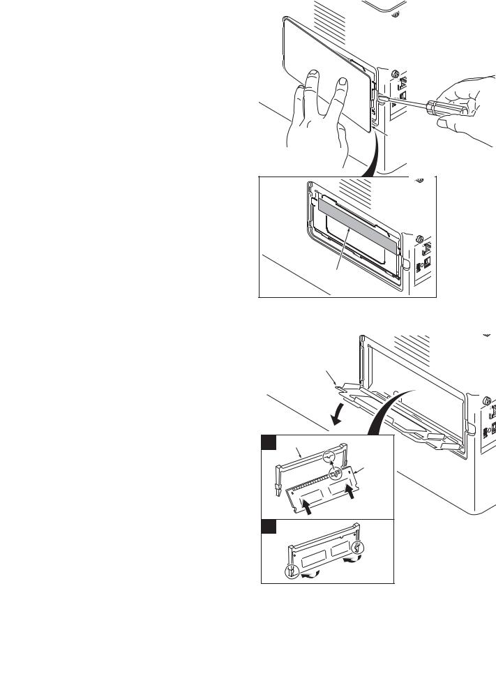
(1) Removing the tapes
Procedure
1. Remove three tapes.
Tape
Tape
Tape
Figure 1-2-3
1-2-3
2L0
1-2-3 Installing the expanded memory (option)
Procedure
1. Turn off printer power switch.
Caution: Do not insert or remove expanded memory while printer power is on.
Doing so may cause damage to the printer and the expanded memory.
2. Remove the right side cover.
3. Remove the tape.
Right side cover
4.Open the memory slot cover.
5.Insert the expanded memory into the memory socket so that the notches on the memory align with the corresponding protrusions in the slot.
6.Close the memory slot cover.
7.Refit the right side cover.
8.Print a status page to check the memory expansion (See page 1-3-2).
If memory expansion has been properly performed, information on the installed memory is printed with the total memory capacity has been increased. Standard memory capacity 128 MB.
Tape |
Figure 1-2-4 |
Memory slot cover
1 Memory socket
Expanded memory
2
Figure 1-2-5
1-2-4

1-2-4 Installing the memory card (optional)
Procedure
1.Turn off printer power switch.
Caution: Do not insert or remove memory card while printer power is on.
Doing so may cause damage to the printer and the memory card.
2.Open the rear cover.
3.Remove two screws and then remove the optional interface slot cover.
4.Insert the memory card into the memory card slot. Push it in all the way.
5.Secure the optional interface slot cover by using two screws.
6.Close the rear cover.
7. Format the memory card before use.
2L0
Rear cover
Screw
Optional interface slot cover
Screw
Figure 1-2-6

 Memory card slot
Memory card
Screw
Screw
Optional interface slot cover
Figure 1-2-7
1-2-5

2L0
This page is intentionally left blank.
1-2-6
2L0-2
1-3-1 Service mode
The printer is equipped with a service function which can be used to maintain and service the machine.
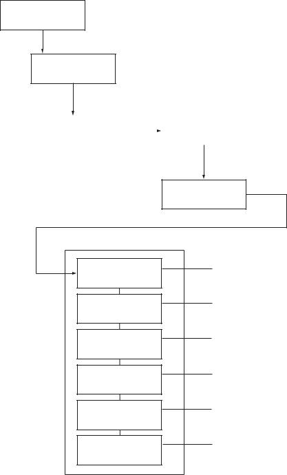
(1) Executing a service item
Message display
Ready
1. Press the MENU key.
Report Print |
> |
2. Press the or key several times
until [Adjust/Maintenance >] is displayed.
Adjust/ |
> |
|
|
>Restart |
Maintenance |
|
|
|
Printer |
|
|
|
||
|
|
|
|
|
3. Press the key.
4.Press the or key several times until [>Service >] is displayed.
>Service >
5. Press the key.
Service mode items
To scroll these items, press the or key repeatedly.
>>Print Status Page
>>Print Network Status Page
>>Print Test Page
>>Write Data
>>Maintenance
>>Developer
To print a status page for service purpose.
(See page 1-3-2)
To print a network status page.
(See page 1-3-7)
Prints a test page which contains halftone.
(See page 1-3-7)
To write data into a USB memory.
(See page 1-3-8)
To reset counter for the maintenance kit.
(See page 1-3-8)
To initialize the developing unit. (toner install mode)
(See page 1-3-9)
1-3-1
2L0-1
(2) Contents of service mode items
|
Service items |
|
Description |
|
|
|
|
|
|
|
|
|
Printing a status page for service purpose |
|
|
|
|
||
|
|
Description |
||
|
Status Page |
|
Prints a status page for service purpose. The status page includes various printing set- |
|
|
|
|
tings and service cumulative. |
|
|
|
|
||
|
|
|
Purpose |
|
|
|
|
To acquire the current printing environmental parameters and cumulative information. |
|
|
|
|
Procedure |
|
|
|
|
1. |
Enter the maintenance mode [>>Print Status Page]. |
|
|
|
2. |
Press the OK key. [Print Status Page?] will be displayed. |
|
|
|
3. |
Press the OK key. [Processing] will be displayed. |
|
|
|
|
Two pages will be printed. |
|
|
|
Completion |
|
|
|
|
|
|
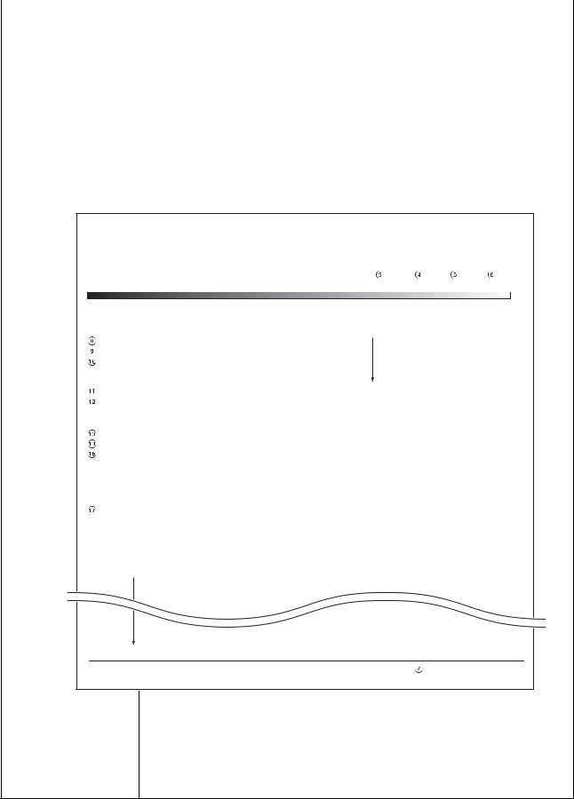
Service Status Page
Printer
 Firmware version 2L0_2000.000.000
  2010.03.01 [XXXXXXXX][XXXXXXXX][XXXXXXXX[XXXXXXXX]
Controller Information
Memory Status
Standard Size |
500.0 KB |
Option Slot |
500.0 KB |
Total Size |
10000.0 KB |
Time
Local Time Zone |
+01:00_Amsterdam |
e-MPS error control |
Y6 |
0 |
Time Server |
10.183.53.13 |
|
|
|
Installed Options
Paper feeder 2 |
Installed |
Paper feeder 3 |
Installed |
Memory Card |
Installed |
Toner coverage
Average(%) / Usage Page(A4/Letter Conversion)
 K: 1.00 / 1111111.00
Last Page (%) 1.00
 FRPO Status
Default Pattern Switch |
B8 |
0 |
Default Font Number |
C5*10000+C2*100+C3 |
00000 |
FRPO parameters |
|
|
[XXXXXXXXXXXXXXXX]
1
Figure 1-3-1Service status page 1
1-3-2
2L0
Service items |
|
Description |
|||
|
|
|
|
|
|
|
|
|
Details of service status page 1 |
||
|
|
|
|
|
|
|
No. |
|
Items |
Description |
|
|
|
|
|
|
|
|
1 |
System version |
- |
|
|
|
|
|
|
|
|
|
2 |
System date |
- |
|
|
|
|
|
|
|
|
|
3 |
Engine software version |
- |
|
|
|
|
|
|
|
|
|
4 |
Engine software boot version |
- |
|
|
|
|
|
|
|
|
|
5 |
Main ROM version |
- |
|
|
|
|
|
|
|
|
|
6 |
Operation panel mask version |
- |
|
|
|
|
|
|
|
|
|
7 |
Machine serial number |
- |
|
|
|
|
|
|
|
|
|
8 |
Standard memory size |
- |
|
|
|
|
|
|
|
|
|
9 |
Option slot memory size |
- |
|
|
|
|
|
|
|
|
|
10 |
Total memory size |
- |
|
|
|
|
|
|
|
|
|
11 |
Local time zone |
- |
|
|
|
|
|
|
|
|
|
12 |
TIme server |
- |
|
|
|
|
|
|
|
|
|
13 |
Optional paper feeder installing information |
Paper feeder 1 |
|
|
|
|
|
|
|
|
|
14 |
Optional paper feeder installing information |
Paper feeder 2 |
|
|
|
|
|
|
|
|
|
15 |
Optional memory card installing information |
- |
|
|
|
|
|
|
|
|
|
16 |
Page of relation to the A4/Letter |
- |
|
|
|
|
|
|
|
|
|
17 |
Coverage on the final output page |
- |
|
|
|
|
|
|
|
|
|
18 |
FRPO setting |
- |
|
|
|
|
|
|
|
|
|
|
|
|
|
|
1-3-3

2L0 |
|
|
|
Service items |
|
|
Description |
Service status page 2 |
|
|
|
Service Status Page |
|
||
Printer |
|
|
|
Firmware version 2L0_2000.000.000 |
2010.03.01 |
[XXXXXXXX][XXXXXXXX][XXXXXXXX[XXXXXXXX] |
|
Engine Information |
|
|
|
NVRAM Version |
XXXXXXXXXXX |
|
|
MAC Address |
00.00.00.00.00.00 |
|
|
1/2 |
|
|
|
100/100 |
|
|
|
0/0/0/0/0/ |
|
|
|
0/0/0/0/0/ |
|
|
|
0/0/0/0/0/0/0/0/ |
|
|
|
0000000/0000000/0000000/0000000/0000000/0000000/ |
|
||
0000000/ |
|
|
|
F00/U00/0/0/0/0/30/ABCDE/1/ |
|
|
|
0000/0000/0000/0000/0000/0000/0000/0000/0000/0000/0000/0000/0000/0000/0000/ |
|||
0000/0000/0000/0000/0000/0000/0000/0000/0000/0000/ |
|
||
0203040508090A0B0C0D0F101112131415161718191A1B1C1D1E1F202122235E |
|||
12345678/11223344/00001234abcd567800001234abcd5678/01234567890123456789012345678901/0008/00/07 |
|||
XXXXXXXX/t/ |
|
|
|
FFFFFFFFFFFFFFFF/FFFFFFFFFFFFFFFF/FFFFFFFFFFFFFFFF/FFFFFFFFFFFFFFFF/ |
|||
FFFFFFFFFFFFFFFF/FFFFFFFFFFFFFFFF/FFFFFFFFFFFFFFFF/FFFFFFFFFFFFFFFF/ |
|||
FFFFFFFFFFFFFFFF/FFFFFFFFFFFFFFFF/FFFFFFFFFFFFFFFF/FFFFFFFFFFFFFFFF/ |
|||
FFFFFFFFFFFFFFFF/FFFFFFFFFFFFFFFF/FFFFFFFFFFFFFFFF/FFFFFFFFFFFFFFFF/ |
|||
00/ |
|
|
|
00000000/00000000/00000000/00000000/ |
|
|
|
00000000/00000000/00000000/00000000/ |
|
|
|
00000000/00000000/00000000/00000000/ |
|
|
|
00000000/00000000/00000000/00000000/ |
|
|
|
00000000/00000000/00000000/00000000/ |
|
|
|
00000000/00000000/00000000/00000000/ |
|
|
|
00000000/00000000/00000000/00000000/ |
|
|
|
00000000/00000000/00000000/00000000/ |
|
|
|
00000000/00000000/00000000/00000000/ |
|
|
|
00000000/00000000/00000000/00000000/ |
|
|
|
00000000/00000000/00000000/00000000/ |
|
|
|
00000000/00000000/00000000/00000000/ |
|
|
|
00000000/00000000/00000000/00000000/ |
|
|
|
00000000/00000000/00000000/00000000/ |
|
|
|
00000000/00000000/00000000/00000000/ |
|
|
|
00000000/00000000/00000000/00000000/ |
|
|
|
00000000/00000000/00000000/00000000/ |
|
|
|
00000000/00000000/00000000/00000000/ |
|
|
|
00000000/00000000/00000000/00000000/ |
|
|
|
00000000/00000000/00000000/00000000/ |
|
|
|
00000000/00000000/00000000/00000000/ |
|
|
|
00000000/00000000/00000000/00000000/ |
|
|
|
00000000/00000000/00000000/00000000/ |
|
|
|
[ABCDEFGHIJ][ABCDEFGHIJ][ABCDEFGHIJ] |
|
||
|
|
2 |
[XXXXXXXXXXXXXXXX] |
|
|
|
|
|
|
Figure 1-3-2Service status page 2 |
|
1-3-4 |
|
|
|

2L0
|
Service items |
|
|
|
|
|
Description |
||
|
|
|
|
|
|
|
|||
|
|
|
Details of service status page 2 |
|
|
||||
|
|
|
|
|
|
|
|
|
|
|
No. |
Items |
|
|
|
|
Description |
|
|
|
|
|
|
|
|
||||
19 |
NV RAM version |
_ Bb 04B29 _ Bb |
04B29 |
|
|||||
|
|
|
|
(a) |
(b) |
(c) |
(d) (e) |
(f) |
|
|
|
|
|
(a) Consistency of the present software version and the database |
|
||||
|
|
|
|
|
_ (underscore): OK |
|
|
||
|
|
|
|
|
* (Asterisk): NG |
|
|
||
|
|
|
|
(b) Database version |
|
|
|||
|
|
|
|
(c) The oldest time stamp of database version |
|
||||
|
|
|
|
(d) Consistency of the present software version and the ME firmware |
|
||||
|
|
|
|
version |
|
|
|
|
|
|
|
|
|
|
_ (underscore): OK |
|
|
||
|
|
|
|
|
* (Asterisk): NG |
|
|
||
|
|
|
|
(e) ME firmware version |
|
||||
|
|
|
|
(f) The oldest time stamp of the ME database version |
|
||||
|
|
|
|
Normal if (a) and (d) are underscored, and (b) and (e) are identical with |
|
||||
|
|
|
|
(c) and (f). |
|
|
|
|
|
|
|
|
|
|
|
|
|
|
|
20 |
Mac address |
- |
|
|
|
|
|
||
|
|
|
|
|
|
|
|
|
|
21 |
Destination information |
- |
|
|
|
|
|
||
|
|
|
|
|
|
|
|
|
|
22 |
Area information |
- |
|
|
|
|
|
||
|
|
|
|
|
|
|
|
|
|
23 |
Margin settings |
0/0 |
|
|
|
(a) Top margin |
|||
|
|
|
|
(a)(b) |
|
|
(b) Left margin |
||
|
|
|
|
|
|
|
|
||
24 |
Top offset for each bin |
0/0/0/0/0 |
|
|
(a) MP tray |
||||
|
|
|
|
(a)(b)(c)(d)(e) |
|
(b) Cassette 2 |
|||
|
|
|
|
|
|
|
|
(c) Cassette 3 |
|
|
|
|
|
|
|
|
|
(d) Duplex |
|
|
|
|
|
|
|
|
|
(e) Page rotation |
|
|
|
|
|
|
|
|
|
||
25 |
Left offset for each bin |
0/0/0/0/0 |
|
|
(a) MP tray |
||||
|
|
|
|
(a)(b)(c)(d)(e) |
|
(b) Cassette 2 |
|||
|
|
|
|
|
|
|
|
(c) Cassette 3 |
|
|
|
|
|
|
|
|
|
(d) Duplex |
|
|
|
|
|
|
|
|
|
(e) Page rotation |
|
|
|
|
|
|
|
|
|||
26 |
L value settings |
0/0/0/0/0/0/0/0 |
|
(a) Top margin (integer) |
|||||
|
|
|
|
(a)(b)(c)(d)(e)(f)(g)(h) |
(b) Top margin (decimal place) |
||||
|
|
|
|
|
|
|
|
(c) Left margin (integer) |
|
|
|
|
|
|
|
|
|
(d) Left margin (decimal place) |
|
|
|
|
|
|
|
|
|
(e) Paper length (integer) |
|
|
|
|
|
|
|
|
|
(f) Paper length (decimal place) |
|
|
|
|
|
|
|
|
|
(g) Paper width (integer) |
|
|
|
|
|
|
|
|
|
(h) Paper width (decimal place) |
|
|
|
|
|
|
|||||
27 |
Life counter |
0000000/0000000/0000000/0000000/0000000/0000000/0000000/ |
|
||||||
|
|
|
|
(a) |
(b) |
(c) |
(d) |
(e) (f) (g) |
|
(a)Printer
(b)MP tray
(c)Cassette 1
(d)Cassette 2
(e)Cassette 3
(f)Duplex printing
(g)Maintenance kit
1-3-5
2L0
|
Service items |
|
|
|
|
|
|
|
|
|
|
|
Description |
|
|
|
||||||
|
|
|
|
|
|
|
|
|
|
|
|
|
|
|
|
|
|
|
|
|
|
|
|
|
|
|
|
|
|
|
|
|
|
|
|
|
|
|
|
|
|
|
|
|
|
|
No. |
Items |
|
|
|
|
|
|
|
|
|
|
Description |
|
|
|
||||||
|
|
|
|
|
|
|
|
|
|
|
|
|
|
|
|
|
|
|
|
|
||
|
28 |
Operation panel lock status |
|
0: Off |
|
|
|
|
|
|
|
|
|
|
|
|
||||||
|
|
|
|
|
|
|
|
|
1: Partial lock |
|
|
|
|
|
|
|
|
|
|
|||
|
|
|
|
|
|
|
|
|
2: Full lock |
|
|
|
|
|
|
|
|
|
|
|||
|
|
|
|
|
|
|
|
|
|
|
|
|
|
|
|
|
|
|
|
|
||
|
29 |
USB information |
|
|
|
0: Not connected |
|
|
|
|
|
|
|
|
|
|||||||
|
|
|
|
|
|
|
|
|
1: Full-Speed |
|
|
|
|
|
|
|
|
|
|
|||
|
|
|
|
|
|
|
|
|
2: Hi-Speed |
|
|
|
|
|
|
|
|
|
|
|||
|
|
|
|
|
|
|
|
|
|
|
|
|
|
|
|
|
|
|
||||
|
30 |
Paper handling information |
|
0: Paper source unit select |
|
|
|
|
|
|||||||||||||
|
|
|
|
|
|
|
|
|
1: Paper source unit |
|
|
|
|
|
|
|
|
|
||||
|
|
|
|
|
|
|
|
|
|
|
|
|
|
|
|
|
|
|
|
|||
|
31 |
Black and white printing dou- |
|
0: All single counts |
|
|
|
|
|
|
|
|
|
|||||||||
|
|
ble count mode |
|
|
|
3: Folio, Single count, Less the 330 mm (length) |
|
|||||||||||||||
|
|
|
|
|
|
|
|
|
|
|
|
|
|
|
|
|
|
|
|
|
|
|
|
32 |
Billing counting timing |
|
|
|
- |
|
|
|
|
|
|
|
|
|
|
|
|
|
|||
|
|
|
|
|
|
|
|
|
|
|
|
|
|
|
|
|
|
|
|
|||
|
33 |
Temperature (machine inside) |
- |
|
|
|
|
|
|
|
|
|
|
|
|
|
||||||
|
|
|
|
|
|
|
|
|
|
|
|
|
|
|
|
|
|
|
|
|
||
|
34 |
LXI calibration information |
|
- |
|
|
|
|
|
|
|
|
|
|
|
|
|
|||||
|
|
|
|
|
|
|
|
|
|
|
|
|
|
|
|
|
|
|
|
|
|
|
|
35 |
Fixed asset number |
|
|
|
- |
|
|
|
|
|
|
|
|
|
|
|
|
|
|||
|
|
|
|
|
|
|
|
|
|
|
|
|
|
|
|
|
|
|
|
|
||
|
36 |
Job end judgment time-out |
|
- |
|
|
|
|
|
|
|
|
|
|
|
|
|
|||||
|
|
time |
|
|
|
|
|
|
|
|
|
|
|
|
|
|
|
|
|
|||
|
|
|
|
|
|
|
|
|
|
|
|
|
|
|
|
|
|
|
|
|
|
|
|
37 |
Media type |
|
|
|
Weight |
|
|
|
|
Fuser |
|
|
|
Duplex |
|
||||||
|
|
|
|
|
|
|
|
|
0: Light |
|
|
|
|
0: Hi |
|
|
|
0: Disable |
|
|||
|
|
|
|
|
|
|
|
|
1: Normal 1 |
|
|
1: Middle |
|
|
|
1: Enable |
|
|||||
|
|
|
|
|
|
|
|
|
2: Normal 2 |
|
|
2: Low |
|
|
|
|
|
|||||
|
|
|
|
|
|
|
|
|
3: Normal 3 |
|
|
3: Vellum |
|
|
|
|
|
|||||
|
|
|
|
|
|
|
|
|
4: Heavy 1 |
|
|
|
|
|
|
|
|
|
|
|||
|
|
|
|
|
|
|
|
|
5: Heavy 2 |
|
|
|
|
|
|
|
|
|
|
|||
|
|
|
|
|
|
|
|
|
6: Heavy 3 |
|
|
|
|
|
|
|
|
|
|
|||
|
|
|
|
|
|
|
|
|
7: Extra Heavy |
|
|
|
|
|
|
|
|
|
|
|||
|
|
|
|
|
|
|
|
|
|
|
|
|
|
|
|
|
|
|
|
|
|
|
|
38 |
SPD information |
|
|
|
- |
|
|
|
|
|
|
|
|
|
|
|
|
|
|||
|
|
|
|
|
|
|
|
|
|
|
|
|
|
|
|
|
|
|
|
|
|
|
|
39 |
RFID information |
|
|
|
- |
|
|
|
|
|
|
|
|
|
|
|
|
|
|||
|
|
|
|
|
|
|
|
|
|
|
|
|
|
|
|
|
|
|
|
|
||
|
40 |
RFID reader/writer version |
|
- |
|
|
|
|
|
|
|
|
|
|
|
|
|
|||||
|
|
information |
|
|
|
|
|
|
|
|
|
|
|
|
|
|
|
|
|
|||
|
|
|
|
|
|
|
|
|
|
|
|
|
|
|
|
|
|
|
|
|
||
|
41 |
Toner install mode informa- |
|
0: OFF |
|
|
|
|
|
|
|
|
|
|
|
|
||||||
|
|
tion |
|
|
|
1: ON |
|
|
|
|
|
|
|
|
|
|
|
|
||||
|
|
|
|
|
|
|
|
|
|
|
|
|
|
|
|
|
|
|
||||
|
42 |
Engine parameter information |
Hexadecimal, 512 bytes |
|
|
|
|
|
|
|
|
|||||||||||
|
|
|
|
|
|
|
|
|
|
|
|
|
|
|
|
|
|
|
|
|
|
|
|
43 |
DRT table number |
|
|
|
- |
|
|
|
|
|
|
|
|
|
|
|
|
|
|||
|
|
|
|
|
|
|
|
|
|
|
|
|
|
|
|
|
|
|
|
|
||
|
44 |
DRT parameter coefficient |
|
- |
|
|
|
|
|
|
|
|
|
|
|
|
|
|||||
|
|
|
|
|
|
|
|
|
|
|
|
|
|
|
|
|
|
|
|
|
|
|
|
45 |
Optional font version |
|
|
|
- |
|
|
|
|
|
|
|
|
|
|
|
|
|
|||
|
|
|
|
|
|
|
|
|
|
|
|
|
|
|
|
|
|
|
|
|
|
|
|
46 |
Optional table version |
|
|
|
- |
|
|
|
|
|
|
|
|
|
|
|
|
|
|||
|
|
|
|
|
|
|
|
|
|
|
|
|
|
|
|
|
|
|
|
|
||
|
47 |
Optional message version |
|
- |
|
|
|
|
|
|
|
|
|
|
|
|
|
|||||
|
|
|
|
|
|
|
|
|
|
|
|
|
|
|
|
|
|
|
|
|
|
|
|
48 |
WEB optional version |
|
|
|
- |
|
|
|
|
|
|
|
|
|
|
|
|
|
|||
|
|
|
|
|
|
|
|
|
|
|
|
|
|
|
|
|
|
|
|
|
|
|
|
|
NOTE: |
|
|
|
|
|
|
|
|
|
|
|
|
|
|
|
|
|
|||
|
|
|
Code conversion |
|
|
|
|
|
|
|
|
|
|
|
|
|
|
|||||
|
|
|
|
|
|
|
|
|
|
|
|
|
|
|
|
|
|
|
|
|
|
|
|
|
|
A |
|
B |
|
C |
|
D |
E |
|
F |
G |
|
H |
|
I |
|
J |
|
|
|
|
|
|
|
|
|
|
|
|
|
|
|
|
|
|
|
|
|
|
|
|
|
|
|
|
|
0 |
|
1 |
|
2 |
|
3 |
4 |
|
5 |
6 |
|
7 |
|
8 |
|
9 |
|
|
|
|
|
|
|
|
|
|
|
|
|
|
|
|
|
|
|
|
|
|
|
|
|
|
|
|
|
|
|
|
|
|
|
|
|
|
|
|
|
|
|
|
|
|
|
|
|
|
|
|
|
|
|
|
|
|
|
|
|
|
|
|
|
|
|
|
|
|
|
|
1-3-6
Loading...