

Konica Minolta bizhub 367, bizhub 287, bizhub 227 Service Manual

SERVICE MANUAL
367/287/227
SECURITY FUNCTION
This Service Manual (Ver. 1.02) describes
bizhub 367/bizhub 287/bizhub 227/bizhub 136DN/bizhub 128DN/
bizhub 122DN/ineo 367/ineo 287/ineo 227/Sindoh N502/
Sindoh N501/Sindoh N500/Sindoh MF3091/Sindoh MF2101/
Sindoh MF2041/Sindoh N512/Sindoh N511/Sindoh N510/
Sindoh N517/Sindoh N516/Sindoh N515
(Version: G00-27)
2016. 3
Ver. 1.02

Security Function Ver. 1.02 Mar. 2016
CONTENTS
Security function
1. Overview ................................................................................................................. 1
2. Compliance with the ISO15408 standard ................................................................ 1
3. Installation of the machine and steps to be performed before operation................. 1
3.1 Unpacking and setting up the machine.................................................................1
3.1.1 Removing the machine ................................................................................. 1
3.1.2 Removing protective tape, packing and other shipping materials ................. 1
3.1.3 Installing the toner cartridge.......................................................................... 2
3.1.4 Installing and replacing the hard disk ............................................................ 2
3.1.5 Installing other options ..................................................................................2
3.1.6 Mounting the accessory parts....................................................................... 2
3.1.7 Connecting the power cord ...........................................................................2
3.1.8 Starting the machine .....................................................................................2
3.1.9 Make the necessary settings.........................................................................2
3.1.10 Performing Non-Image Area Erase Check....................................................3
3.1.11 Configuring other options ..............................................................................3
3.1.12 Connecting the network cable ....................................................................... 3
3.1.13 Network setting ............................................................................................. 3
3.1.14 Restarting the machine .................................................................................3
3.1.15 Adjusting each option .................................................................................... 4
3.1.16 Affixing the paper size label ..........................................................................4
3.1.17 Installing the user’s guide holder...................................................................4
3.1.18 Affixing the panel sheet ................................................................................. 4
3.1.19 Checking for parts mounted on the machine ................................................ 5
3.1.20 Switch setting for secured start .....................................................................5
3.1.21 Setting for Custom Function Pattern Selection .............................................5
4. Precautions for operation control............................................................................. 6
5. Checking the firmware version number...................................................................8
5.1 Security authentication firmware version number ................................................. 8
6. Accessing the Service Mode ................................................................................... 8
6.1 Access method to the Service Mode ....................................................................8
6.2 Access lock of Service Mode.............................................................................. 10
6.2.1 Access lock release procedure ...................................................................10
7. Enhancing the security function ............................................................................ 11
7.1 Details of settings ............................................................................................... 11
7.2 Security enhancing procedure ............................................................................ 12
i

Security Function Ver. 1.02 Mar. 2016
7.2.1 Making and checking the service settings...................................................12
7.2.2 Requests to the administrator .....................................................................16
7.2.3 Functions disabled by the setting of Enhanced Security Mode...................16
7.2.4 Functions whose settings are changed by Enhanced Security Mode ......... 17
8. Service Mode functions ......................................................................................... 20
8.1 Firmware Version................................................................................................20
8.1.1 Checking the firmware version number.......................................................20
8.2 CE Authentication function.................................................................................. 21
8.2.1 Setting the CE Authentication function........................................................21
8.3 Administrator Password function.........................................................................22
8.3.1 Setting the administrator password ............................................................. 22
8.4 CE Password function......................................................................................... 24
8.4.1 Setting the CE password.............................................................................24
8.5 Initialization function ........................................................................................... 27
8.5.1 Initialize method ..........................................................................................29
8.6 HDD Format........................................................................................................30
8.6.1 HDD format execution procedure................................................................31
8.7 HDD installation setting ...................................................................................... 32
8.7.1 HDD installation setting procedure..............................................................32
8.8 Operation ban release time setting ..................................................................... 33
8.8.1 Operation ban release time setting procedure ............................................33
8.9 Administrator Unlocking function ........................................................................34
8.9.1 Administrator Unlocking function procedure................................................ 34
9. Overwrite All Data function....................................................................................35
9.1 Overwrite All Data procedure..............................................................................35
9.2 Items to be cleared by Overwrite All Data........................................................... 35
9.2.1 Items cleared by Overwrite All Data ............................................................ 35
10. Firmware rewriting................................................................................................. 37
10.1 Outline ................................................................................................................ 37
10.2 USB memory ...................................................................................................... 37
10.2.1 Preparation..................................................................................................37
10.2.2 Procedure....................................................................................................37
10.2.3 Action when data transfer fails ....................................................................40
10.2.4 Entering the machine type information........................................................41
11. FAX function..........................................................................................................43
11.1 Installing/setting procedure of the FAX kit...........................................................43
11.1.1 Install procedure..........................................................................................43
11.1.2 Installation of the ferrite core ....................................................................... 43
11.1.3 Connecting the modular cable..................................................................... 43
ii

Security Function Ver. 1.02 Mar. 2016
11.1.4 Affixing the labels ........................................................................................ 43
11.1.5 Setting procedure ........................................................................................ 44
iii

Security Function Ver. 1.02 Mar. 2016 1. Overview
1. Overview
This Service Manual contains the essential operating procedures and precautions for using
the security functions.
2. Compliance with the ISO15408 standard
This machine has an enhanced security function: Set the Enhanced Security Mode, in
Administrator Settings, to [ON].
This machine offers the security functions that comply with the ISO/IEC15408 (level: EAL2)
and U.S. Government Approved Protection Profile - U.S. Government Protection Profile for
Hardcopy Devices Version 1.0 (IEEE Std 2600.2
TM
-2009).
3. Installation of the machine and steps to be performed before operation
The service engineer should first perform the following steps before setting the machine for
the Enhanced Security Mode.
The ISO15408 evaluation for this machine assumes that the hard disk is installed in the
machine. Thus, make sure that the hard disk has been installed.
3.1 Unpacking and setting up the machine
• Be sure to correctly follow the procedures in order as explained in this Manual. If
you do not follow the procedure in order, the image trouble may occur.
• If any part requires replacement due to a machine trouble, perform the relevant
replacement procedure appropriately.
3.1.1 Removing the machine
1. Make sure that the machine package has not been previously unpacked.
2. Unpack and remove the machine package.
3. Remove the machine, holding it by the locations on the left side and the handles on the
right side and keeping it level.
Machine mass: approx. 56.5 kg/124-9/16 lb
• Make available collective manpower of an appropriate size for transporting the machine.
• Before attaching the machine to the paper feed cabinet, make sure that the supplied con-
nector cover is not attached.
• When attaching the machine, as the reference fit the machine with the corner of the
paper feed cabinet.
• When holding the transportation handles, be careful not to catch your fingers in the
machine.
3.1.2 Removing protective tape, packing and other shipping materials
1. Remove the protective tape and the protective materials.
1

3. Installation of the machine and steps to be
3.1.3 Installing the toner cartridge
Since a toner cartridge is not supplied with the machine, purchase one separately.
1. Shake the toner cartridge up and down and left to right 5 to 10 times respectively.
Shake the cartridge adequately. Otherwise, it may cause trouble.
2. Insert the toner cartridge into the machine. Make sure that the blue label position of the
toner cartridge is matched with the one of the machine side.
3. Push the toner cartridge all the way in and rotate it clockwise to lock it. Make sure that
the toner cartridge is pushed all the way in.
4. Close the front door.
3.1.4 Installing and replacing the hard disk
1. Make sure that the package has not been previously unpacked.
Pay attention to the following.
• If the security seal is peeled off.
• If the PP tape on the package has been peeled off or re-stuck.
2. Take out the hard disk from the package.
3. Make sure that the following information is correct.
• Product Name: HD-522
• Part Number: A878WY1
4. See the service manual for methods of installation and replacement.
After the main power switch is turned ON, check if access can be made normally.
3.1.5 Installing other options
See the “Installation procedures” of the installation manual for each option.
3.1.6 Mounting the accessory parts
1. Set the stylus pen.
2. Attach the supplied connector cover to the machine. (One supplied screw)
performed before operationSecurity Function Ver. 1.02 Mar. 2016
3.1.7 Connecting the power cord
1. Connect the power cord. This may not be performed depending on the applicable mar-
keting area.
2. Plug the power cord into the power outlet.
3.1.8 Starting the machine
1. Turn ON the power switch on the right side of the main body.
3.1.9 Make the necessary settings
• Date & Time Setting/Time Zone Setting ([Service Mode] → [Date & Time Setting/Time
Zone Setting screen (To display the Date & Time Setting/Time Zone Setting screen,
press Stop → 1 → 1 → 4 → 4 → Clear on the control panel)])
• Serial number input ([Service Mode] → [System 1] → [Serial Number])
• Unit change ([Service Mode] → [System 2] → [Unit Change])
2

3. Installation of the machine and steps to be
3.1.10 Performing Non-Image Area Erase Check
Perform the below at the site where customer uses the machine.
1. Touch these keys in this order: [Service Mode] → [Machine] → [Non-Image Area Erase
Check].
Open fully original options if loaded.
• Do NOT place a document on the document glass.
• Clean the document glass if dirty.
2. Press the Start key.
3. Make sure that “Result” is “OK”. If “Result” is “NG1” or “NG2”, review the place and
direction of installation, or take measures to block the light source (by covering it, etc.),
then perform installation checking again. If a fluorescent light or other bright light
sources exist right above the machine, the light source can hinder installation checking
and cause operation errors in the Non-Image Area Erase Check.
4. Touch “OK.”
3.1.11 Configuring other options
1. See the “Configuration procedures” of the installation manual for each option.
3.1.12 Connecting the network cable
1. Connect the main body and networking equipment (HUB) using the network cable. The
following shows the recommended network cables that correspond to each communication speed.
• 10BaseT/100BaseTX: Category5
• 1000BaseT: Category5E, Category6
2. Check LEDs for lighting conditions.
• LED1: Should light up steadily if the link network connection has been made.
• LED2: Should blink according to the communications status of the ACT network.
performed before operationSecurity Function Ver. 1.02 Mar. 2016
3.1.13 Network setting
Make the TCP/IP address setting for the network. Consult the network administrator for the
setting value to be entered and make settings as required.
1. Touch these keys in this order: [Utility] → [Administrator Settings] → [Network Settings]
→ [TCP/IP Settings] → [IPv4 Settings].
2. Touch “Manual Input” of IP Application Setting Method and make the following settings.
IP Address: IP address of the controller
Subnet Mask: Subnet mask of the network, to which the machine is connected
Default Gateway: IP address of the default gateway
3. Touch “OK.”
4. Touch “OK” after the “TCP/IP Settings” screen is displayed.
5. Select the function to be used as follows: [Forward] → [Detail Settings] → [PING Confir-
mation], and make the operation check of TCP/IP.
3.1.14 Restarting the machine
1. Turn the power switch on the right side of the main body OFF and ON again after 10 or
more seconds have passed.
3

3. Installation of the machine and steps to be
3.1.15 Adjusting each option
1. See the “Adjustment procedures” of the installation manual for each option.
After completing all the steps, take a sample copy, and confirm the image. If image
troubles occur, first turn OFF and ON the Main Power Switch, and then redo the
steps from “Date & Time Setting/Time Zone Setting” to “Unit change.”
3.1.16 Affixing the paper size label
1. Affix the paper size labels that correspond to the sizes of paper used in each tray.
3.1.17 Installing the user’s guide holder
1. Install the user’s guide holder.
3.1.18 Affixing the panel sheet
1. Affix the supplied panel sheet to the surface of the operation panel. The panel sheet is
affixed on customer request. The panel sheet must be kept by the customer.
performed before operationSecurity Function Ver. 1.02 Mar. 2016
4
3. Installation of the machine and steps to be
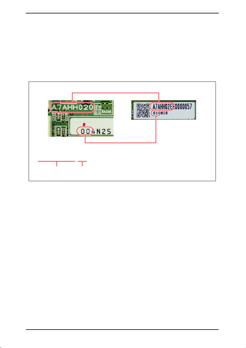
3.1.19 Checking for parts mounted on the machine
1. Check that the part numbers of the MFP board and the eMMC board are as specified
below.
<MFP board>
• A7AHH020-07
<eMMC board>
• A7AHH02E-02
A part number is a 10-digit number consisting of A (8 digits) and B (2 digits) as in the portions encircled in red below.
performed before operationSecurity Function Ver. 1.02 Mar. 2016
A
B
XXXXXXXX-XX
A (8 digits) B (2 digits)
A7AHS1E024DA
3.1.20 Switch setting for secured start
1. Open the rear cover of the machine and place switch 1 of "SW1" on the MFP board in
the ON position.
3.1.21 Setting for Custom Function Pattern Selection
1. Copy the Custom Function Pattern Selection setting file (XXX_v1.0_ISO15408.cpd) to
the route directory of a USB memory.
2. Connect the USB memory to the USB port of the MFP.
3. Call the service mode to the screen.
4. Touch [System 2] → [Custom Pattern].
5. Select [Custom Pattern 1], [Custom Pattern 2], or [Custom Pattern 3].
6. Select [Import] and press the start key to import the data.
7. Select functions as follows: [Administrator Settings] → [System Settings] → [Custom
Display Settings] → [Custom Function Pattern Selection] → [Send/Save]. Then, select
the registered custom pattern ([ISO15408]).
* XXX in the cpd file and the Custom Pattern denotes the product name that represents the
series.
5

Security Function Ver. 1.02 Mar. 2016 4. Precautions for operation control
4. Precautions for operation control
A. Requirements of the service engineer
The service engineer should take full responsibility for controlling the machine during his or
her procedures for setting up and servicing the machine so that no improper operations are
performed.
<To achieve effective security>
• The service engineer who sets up and services the machine should have completed the
course in security and be certified accordingly.
• The service engineer should swear that he or she would never disclose information as it
relates to the settings of this machine to anybody in accordance with the Installation
Checklist contained in User’s Guide [Security Operations].
• The service engineer should perform his or her physical service jobs in the presence of
the administrator of the machine.
B. Protection of setting data in Service Mode
The CE password used to access Service Mode must be adequately controlled by the service engineer concerned to ensure that it is not leaked. Make sure that any password that
could be easily guessed by a third person is not used as the CE password.
<To achieve effective security>
The CE password should:
• Not be one that is easily guessed by third persons.
• Not be known by any third person.
• Be changed at regular intervals.
• Be set again quickly if one has been initialized.
C. Machine maintenance control
When the service engineer performs maintenance service jobs for the machine, he or she
should check the firmware version (MFP Card Version, MFP Controller BOOT Program),
and make sure that the system has not been altered.
The service engineer should take the following precautions when the user is to purchase an
additional option.
• For an option that requires that Enhanced Security Mode be turned “OFF” before the
option can be used on the machine, notify the user that the mounting of the option makes
the machine not guaranteed by the ISO15408 certification.
• Applications subject to the ISO15408 security evaluation and certification are described
in User’s Guide Security Operations. If any application (including options) not described
in the User’s Guide is to be used, notify the user that the use of the application is not
guaranteed by the ISO15408 certification.
When the Enhanced Security Mode is set to [OFF], make various settings according to the
installation checklist and then have the administrator set the Enhanced Security Mode to
[ON] again.
D. Miscellaneous
The service engineer should explain to the administrator of the machine that the languages, in which the contents of the User’s Guide [Security Operations] have been evaluated, are Japanese and English. He or she should also explain the way how to get the
manual in the language, in which it is evaluated.
In addition, the service engineer should promptly provide the version of the User’s Guide
that has been evaluated for the user whenever the user needs one.
6

Security Function Ver. 1.02 Mar. 2016 4. Precautions for operation control
The following lists the manuals compatible with bizhub 367/bizhub 287/bizhub 227/bizhub
136DN/bizhub 128DN/bizhub 122DN/ineo 367/ineo 287/ineo 227/Sindoh N502/Sindoh
N501/Sindoh N500/Sindoh MF3091/Sindoh MF2101/Sindoh MF2041/Sindoh N512/Sindoh
N511/Sindoh N510/Sindoh N517/Sindoh N516/Sindoh N515 (Version: G00-27).
• bizhub 367/287/227 User’s Guide Ver. 1.00 A7AH-9590BA-00
• bizhub 367/287/227 User’s Guide Security Operations 2016. 3 Ver. 1.02
• bizhub 367/287/227 SERVICE MANUAL SECURITY FUNCTION 2016. 3 Ver. 1.02
• bizhub 367/287/227 SERVICE MANUAL Ver. 1.00: 2015/04/30
7
Security Function Ver. 1.02 Mar. 2016 5. Checking the firmware version number
5. Checking the firmware version number
• Confirm the need to enhance or not to enhance the security function with the administra-
tor of this machine: If administrator wants to enhance, check the firmware version (MFP
Card Version, MFP Controller BOOT Program).
• If the firmware version number of this machine is different from numbers shown in the list
below, it will be necessary to re-write to the firmware version corresponding to security.
Refer to P.37 for the method of how to re-write the firmware.
5.1 Security authentication firmware version number
MFP Card Version MFP Controller BOOT Program
bizhub 367/287/227 A7AH0Y0-F000-G00-27 A7AH0Y0-1E00-G00-01
Refer to P.20 for the method of checking the firmware version.
6. Accessing the Service Mode
6.1 Access method to the Service Mode
1. Press Menu.
2. Touch [Counter].
3. Touch [Display Keypad].
4. Press the following keys in this order:
Stop → 0 → 0 → Stop → 0 → 1
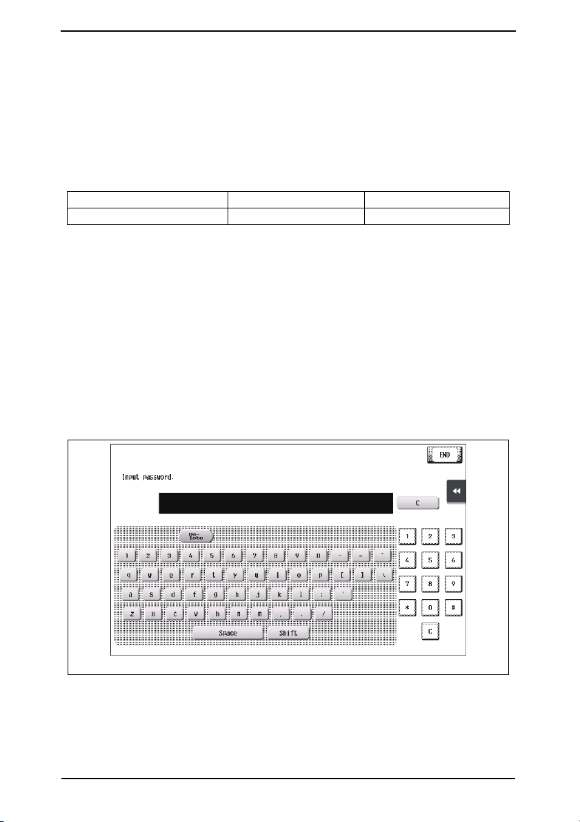
5. Enter the CE password.
NOTE
• Authentication using the CE password is carried out only if “ON” is set for
[CE Authentication] as accessed through [Service Mode] → [Enhanced Security].
A7AHS1E001DA
NOTE
• The CE password entered is displayed as “✱.”
• NEVER forget the CE password. When forgetting the CE password, call responsi-
ble person of KONICA MINOLTA (hereafter called KM).
8
Security Function Ver. 1.02 Mar. 2016 6. Accessing the Service Mode
• If a wrong CE password has been entered, no further entry can be made for 5 sec.
Wait, therefore, for at least 5 sec. before attempting to enter the correct CE password.
• Each time a wrong CE password is entered, the CE password illegal access count
is incremented by one.
When the access to the Service Mode has been successful with the correct CE
password entered, the CE password illegal access count is cleared and reset to 0.
• When “ON” is set for Enhanced Security Mode, access to the Service Mode
through the CE password is restricted by the number of times (1 to 3) set for Prohibited Functions When Authentication Error.
If the CE password illegal access count exceeds the set number of times, the
machine is then set into an access lock state. Then, access to the Service Mode
cannot be made until the access lock state is released.
For the procedure to release the access lock state, see P.10.
• To go from the CE password screen to another, enter the CE password and call the
Service Mode menu to the screen. Then, quit the Service Mode. You can also exit
from the CE password screen by turning OFF and ON the power key; however, be
careful that any jobs entered will be cleared at this time.
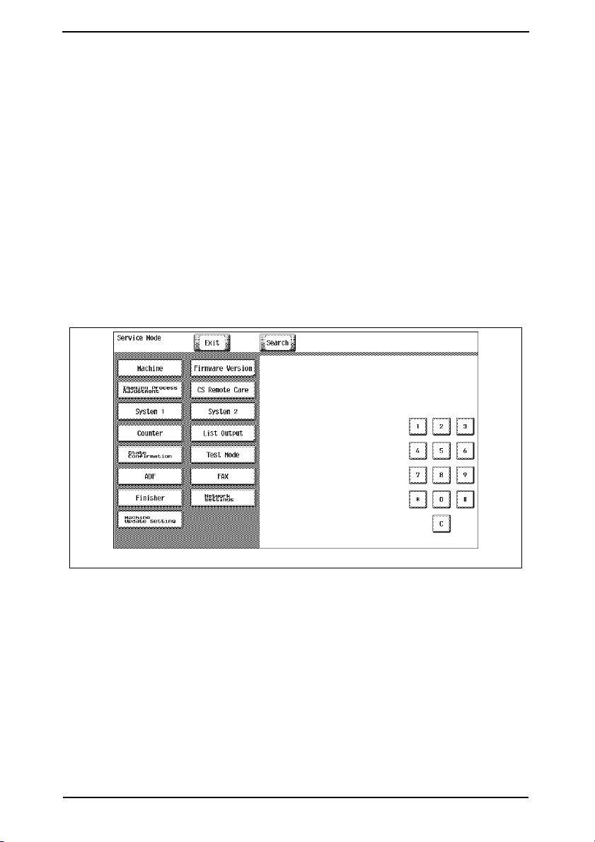
6. The Service Mode screen will appear.
A7AHS1E002DA
NOTE
• If you leave the site with the Service Mode setting screen being displayed, unau-
thorized changes could occur for any set values. When you finish the setting of
Service Mode, or if you have to leave the site by necessity when the Service Mode
has been set, be sure to touch [Exit] to the basic screen.
9
Security Function Ver. 1.02 Mar. 2016 6. Accessing the Service Mode
6.2 Access lock of Service Mode
• Use the following procedure to release the access lock state of the Service Mode.
Releasing the access lock state will also clear the illegal access count reached in CE
authentication.
6.2.1 Access lock release procedure
1. Turn off the main power switch and turn it on again more than 10 seconds after.
2. Press Menu.
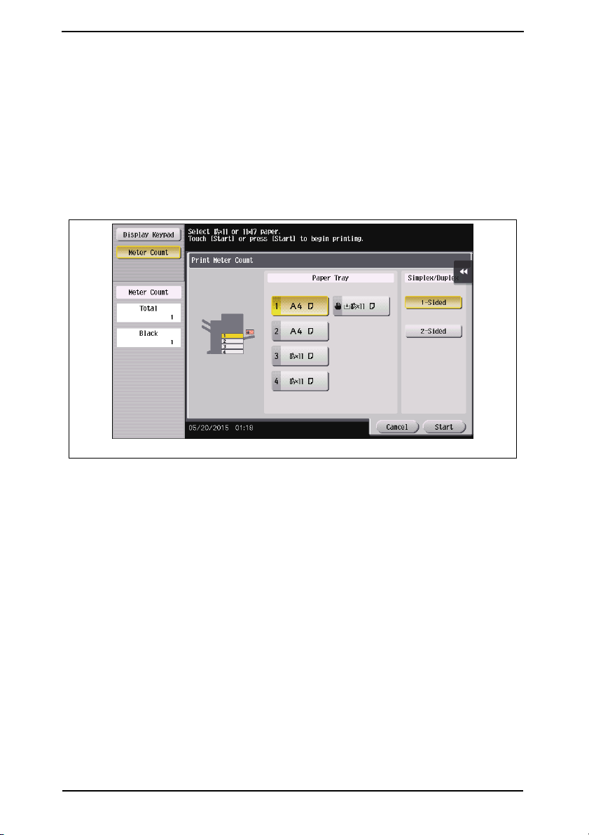
3. Touch [Counter].
4. Touch [Print List].
5. Touch [Display Keypad].
A7AHS1E003DA
6. Press the following keys in this order:
Stop → 0 → 9 → 3 → 1 → 7
(Performing this step will start the access lock release timer.)
7. Once started, the access lock release timer measures time intervals.
The access lock state is released when the period of time set through [Service Mode]
→ [Enhanced Security] → [Operation Ban release time] elapses.
See P.33
10

Security Function Ver. 1.02 Mar. 2016 7. Enhancing the security function
7. Enhancing the security function
• Perform the Enhanced Security Mode procedures while making checks of installation
checklist in User’s Guide [Security Operations].
• To make the Enhanced Security Mode, service settings must first be made. Make the
necessary service settings and check that they have been correctly made.
7.1 Details of settings
Item Setting/Check Default Setting
CE Authentication Check the setting of [ON] [ON]
CE Password Set arbitrarily. 9272927292729272
Image Controller Setting Check the setting of [Controller 0]. [Controller 0]
HDD installation setting Check the setting of [Installed]. [Installed]
Management Function Choice Check the setting of [Unset]. [Unset]
NOTE
• If any one of the above functions is not set properly, the machine does not allow
the Enhanced Security setting to be made.
• The CE password must be set to any value other than the default one.
• If fax functions are to be used, check that the fax kit has been mounted and set up
properly.
See P.43
• In addition to setting the Enhanced Security Mode, the service engineer disables
the following functions and operates and manages the machine under a condition
in which those functions are disabled.
Item Setting
IP Address Fax
Internet Fax
Print Function via USB Port
Using [Service Mode]
set [IP Address Fax] to [OFF].
Using [Service Mode]
set [Internet Fax] to [OFF].
Select [Bit Assignment: 3] or [HEX Assignment: 08] for [Service
Mode]
→ [System2] → [Software Switch Setting] → [Switch No.:
70]. (To restrict use of the print function via a USB port.
→ [System 2] → [Network Fax Settings],
→ [System 2] → [Network Fax Settings],
11
 Loading...