


710-0003
Natural Gas Conversion Kit
Instructions
For questions about features, operation/performance, parts, accessories or service, call:
1-877-373-2301
Ensemble de Conversion Pour Gaz Naturel
Instructions
Pour des questions à propos des caractéristiques, du fonctionnement/rendement, des pièces, des accessoires ou du service,
composer le : 1-877-373-2301
Juego de Conversión a Gas Natural
Instrucciones
Para consultas respecto a características, funcionamiento, rendimiento, piezas, accesorios o servicio técnico, llame al:
1-877-373-2301
Models / Modelos / Modèles: 710-0003
Table of Contents / Índice / Table des matières …………….2
19000375A0

TABLE OF CONTENTS
Safety Instruction---------------------------------------
Tools and parts for Gas Conversion.............................
Conversion from LP Gas to Natural Gas……………....
Check and adjust burner………………………………...
Limited Warranty………………………………………….
ÍNDICE
Instrucciones de Seguridad…………………………...
Herramientas y piezas para la conversión de gas……..
Conversión de gas LP a gas natural………………….....
Revise y regule los quemadores…………………………
Garantía Limitada………………………………………….
TABLE DES MATIÈRES
Instructions de sécurité………………………….………
Outils et pièces pour conversion de gaz.........................
Conversion de propane à gaz naturel …………...……...
Contrôle et réglage des brûleurs...……………………….
Garantie Limitée……………………………………..…….
21
22
23-26
27
28
12
13
14-17
18
19
3
4
5-8
9
10
2

SAFETY INSTRUCTIONS
DANGER
If you smell gas:
1. Shut off gas to the appliance.
2. Extinguish any open flame.
3. Open lid.
4. If odor continues, keep away from the
WARNING
1. Do not store or use gasoline or other
flammable liquids or vapors in the vicinity of
this or any other appliance.
2. An LP cylinder not connected for use shall
not be stored in the vicinity of this or any other
3
IMPORTANT SAFETY INSTRUCTIONS
WARNING: To reduce the risk of fire injury to persons, or damage when using NG Conversion Kit & and outdoor cooking
gas appliance, follow basic precautions, including the following:
Gas conversions must be done by a qualified installer.
The connector is intended only for use outdoors with portable appliance that may be moved for convenience of
operation.
Connectors are designed for movement after installation, but must not be kinked, twisted or torque. Periodic visual
inspection should be made to determine that the connector is suitable for continued use.
Connect with damaging foreign objects or substances must be avoided.
Connected hose assembly shall be of adequate length and capacity for intended application. Final assembly must be
tested for leaks.
Caution: Test for leaks only with leak test solution. Rinse with clear water after leak test to remove any corrosive residue.
DO NOT USE OPEN FLAME TO TEST FOR GAS LEAKS.
SAVE THESE INSTRUCTIONS
appliance and immediately call your gas
supplier or your fire department
appliance.
In the State of, the following installation instructions apply:
Installations and repairs must be performed by a qualified or licensed contractor, plumber, or gasfitter qualified or
licensed by the State of Massachusetts.
If using a ball valve, it shall be a T-handle type.
A flexible gas connector, when used, must not exceed.

Tools and Parts for Gas Conversion
Gather the required tools and parts before starting installation.
Read and follow the instructions provided with any tools listed
here.
Tools needed
Phillips screwdriver
Pipe wrench
Adjustable wrench
6 mm socket and wrench or
6 mm nut driver
Thin flat-blade screwdriver
Pliers
Pipe thread sealant certified
for LP gas
IMPORTANT:
Gas conversions must be done by a qualified
installer. Before proceeding with conversion, shut off the
gas supply to the appliance prior to disconnecting the
electrical power.
If there are damaged or missing parts when you unpack
this kit, call 1-877-373-2301. DO NOT have your
QUALIFIED GAS TECHNICIAN attempt to install this kit
until you receive replacement for any damaged or
missing parts.
Parts needed
Natural gas orifices (supplied with grill)
Note: This manual covers several different models. The grill
you have purchased may have some or all of the features
listed. The locations and appearances of the features shown
here may not match those of your model. Please refer to
your grill’s manual for specific instructions or contact
customer service for information at 1-877-373-2301.
10 ft (3.0 m) Natural gas hose with quick connector
5.9" (150 mm) Natural gas regulator hose
6 mm nut driver
6 mm wrench
Hex Key
Parts supplied
Natural gas regulator 4" W.C. (marked “Natural Gas
Regulator)
4
Conversion from Liquid Propane (LP) to Natural Gas (NG)
Installation of the regulator
1. Turn off the main gas supply valve.
2. Unplug grill or disconnect power.
3. Disconnect 20 lb LP gas fuel tank (if present).
4. Turn off all burner control valves.
5. Remove the 20 lb LP gas fuel tank (if present) from the grill
cart.
6. Use an adjustable wrench to remove the LP regulator from
the manifold.
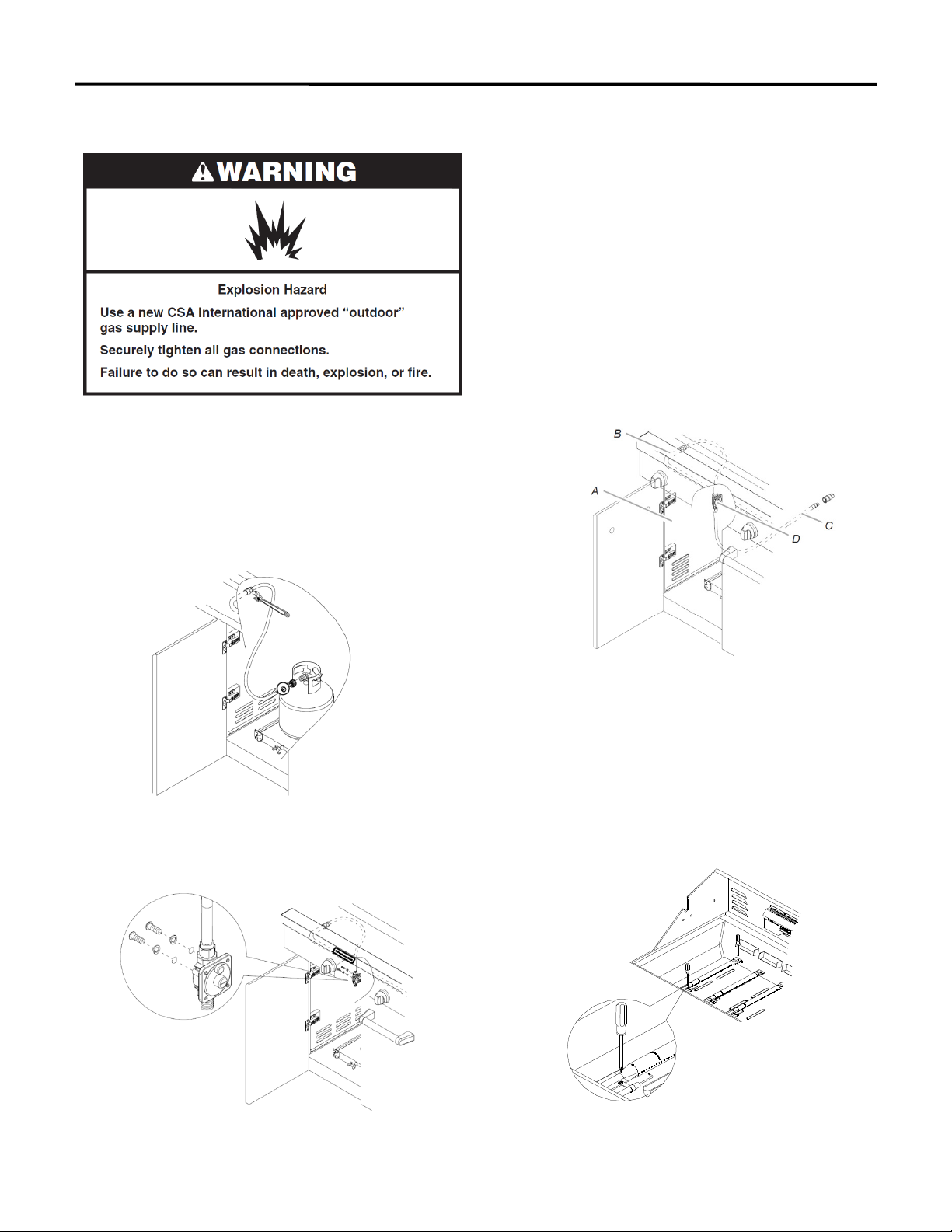
Make Gas Connection
1. A combination of pipe fittings must be used to
connect the grill to the existing gas line.
The 10 ft (3.0 m) PVC flexible gas supply hose design-
certified by CSA must be used.
Pipe-joint compounds suitable for use with Natural gas
must be used. Do not use Teflon®† tape.
There must be a certified manual shutoff valve in the
gas supply line near the grill for easy access.
2.Connect the brass connector on one end of the 10 ft
(3.0 m) PVC flexible gas supply hose (supplied) to the
Natural gas pressure regulator.
3.Connect the quick connector on the other end of the
10ft (3.0 m) PVC flexible gas supply hose to the rigid
Natural gas supply pipe.
7. Use an adjustable wrench to install the Natural gas
regulator hose to the manifold and secure. Attach the
Natural gas regulator to the side panel inside the grill cart
with the two screws that are preassembled on the
regulator.
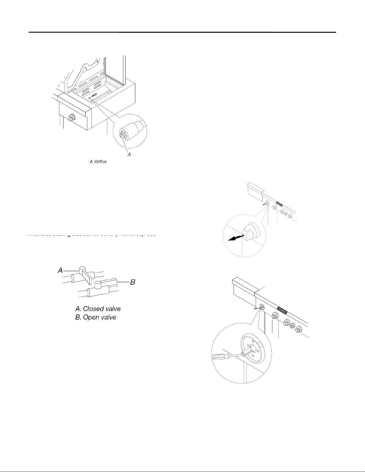
Change Grill Burner Valve Orifices
1. Remove the grates and flame tamers.
2. Remove the screws and pin that hold the burner in
place. Set the screws and pin aside. Remove the
burner from the grill by lifting the burner out.
A.Side panel
B.Manifold
C.10ft. (3.0m) PVC gas hose
D.Natural gas pressure regulator/hose assembly
5
†®TEFLON is a registered trademark of E.I. Du Pont De Nemours and Company.
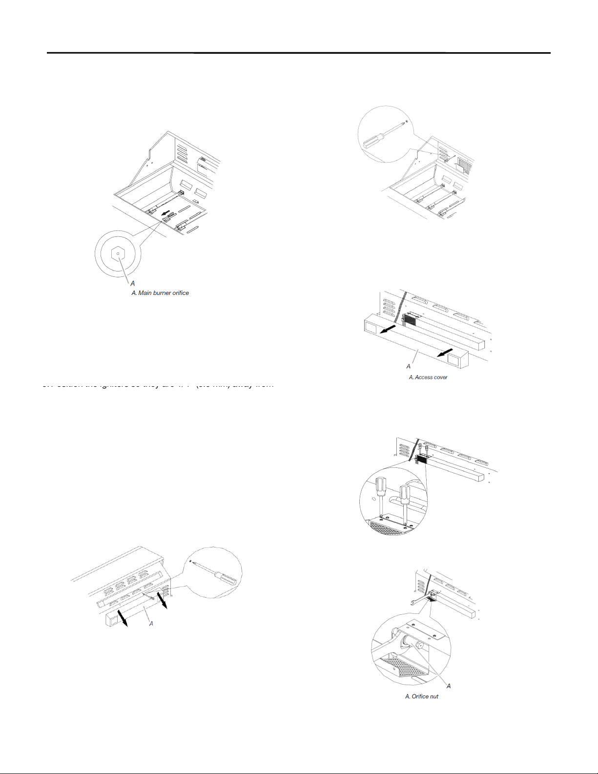
3. Use a 6 mm socket and wrench or 6 mm nut driver to
remove the brass orifice from the end of gas valve. The
main burner NG orifice is located behind the LP orifice, so
no additional orifice needs to be installed.
4. Reinsert the burner and reattach using the 2 screws or
pin previously removed. Repeat the procedure for each
main burner.
2. Using a Phillips screwdriver, remove the screws at the
back of grill from inside the grill.
IMPORTANT: Check that the NG orifice is properly
installed inside of the burner opening.
3. Remove the access cover at the back of the grill hood by
removing the 4 screws (2 screws on each side of the
rotisserie infrared burner).
5.
Position the igniters so they are 1/4" (6.0 mm) away from
each burner.
IMPORTANT: Only Main Burners have the NG orifice pre-
installed behind the LP orifice. All other burners required LP
orifice to be removed and NG orifice to be installed.
Change the Rotisserie/Infrared Burner Orifice
1. Using a Phillips screwdriver, unscrew the screws and
remove the rotisserie/infrared burner wind baffle.
4. Using a Phillips screwdriver, remove the screws holding
the spider guard to the burner.
5. Use 24 mm wrench to remove the orifice nut.
6
A. Wind Baffle
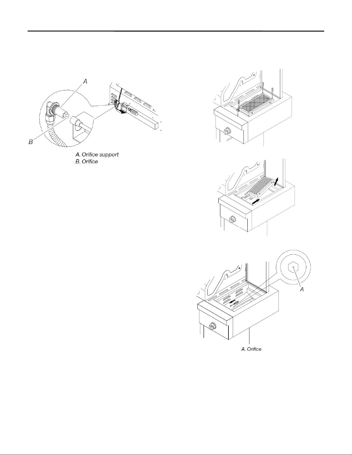
6. Take out the orifice support, and then use a 6 mm socket
and wrench or 6 mm nut driver to remove the LP orifice at
the end of the supply pipe. Replace with Natural gas
orifice.
Change the Sear burner orifices
1. Remove the screw securing the igniter and the 2 searing
side burner screws.
2. Lift the searing side burner out of the grill.
IMPORTANT: Check that the orifice is properly installed
inside of supply pipe.
7. Reinstall the orifice support and supply pipe and tighten the
nut with a 24 mm wrench.
8. Reinstall the spider guard, access cover, and wind baffle.
4. Use 6 mm socket wrench or 6 mm nut driver to remove
the orifice. Replace with the Natural gas orifice.
3. Locate the LP gas orifice to the end of the valve.
7
Adjust High Flame Setting Screw
When converting from LP to Natural gas, you will need to
adjust the high flame setting screw for ideal burner flame
height.
1. Remove each control knob for the main burners and side
burner.
Record Conversion
1. The appliance nameplate is located inside the grill cabinet
on the left-hand cabinet side or inside of the cabinet door.
With a permanent marker, check the box next to ‘’Natural
gas’’ and mark through ‘’LP -Propane.’’ In the last page of
the Use and Care Guide, write ‘’Converted to Natural
Gas.’’ Also record the conversion date and the
technician/company that performed the conversion.
NOTE: Place LP gas parts in plastic parts bag for future use
and keep with pack containing literature.
5. Reinstall the searing side burner. Make sure that the igniter
is out of the way to allow proper positioning of burner. Use
Phillips screwdriver to attach the mounting screws.
6. Use Phillips screwdriver to reattach the igniter and searing
side burner plate.
IMPORTANT: Check that the orifice is properly installed
inside of valve.
2. Use a flat-blade screwdriver to turn the high flame setscrew
counterclockwise approximate 90 degree.
3. Check that burner operates at the new high flame setting. It
may be necessary to adjust the screw setting slightly more to
get the ideal burner flame height.
7.
Reinstall searing side burner
cover (if removed).
Use
Phillips screwdriver to attach mounting screws.
8. Open the manual shutoff valve in the gas supply line. The
valve is open when the handle is parallel to the gas pipe.
9. Test all connections using an approved noncorrosive leak-
detection solution. Bubbles will show a leak. Correct any
leak found.
8
Check and Adjust Burner
The burners are tested and factory-set for most efficient
operation. However, variations in gas supply and other
conditions may make minor adjustments to air shutter or
low flame setting necessary.
It is recommended that a qualified technician make burner
adjustments.
NOTE: The rotisserie burner cannot be adjusted.
Checking and adjusting the grill burner flames requires
removing the grates and flame tamers.
Burner Flame Characteristics
The flames of the grill burners and side burners (on some
models) should be blue and stable with no excessive noise
or lifting (LP gas flames will have a slightly yellow tip). A
yellow flame indicates not enough air. If flame is noisy or
lifts away from the burner, there is too much air. Some
yellow tips on flames when the burner is set to HIGH
setting are acceptable as long as no carbon or soot
deposits appear. The flames should be approximately 1"
(2.5 cm) high.
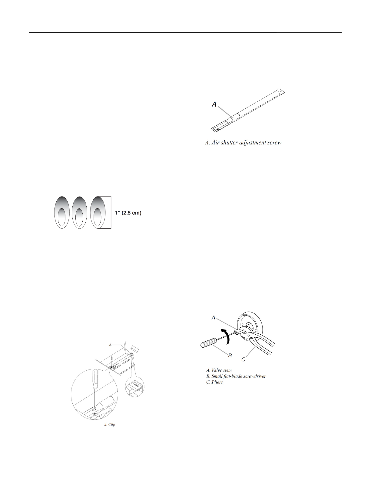
6. If flame is yellow (not enough air), turn air shutter
adjustment screw counterclockwise. If flame is noisy or
lifts away from burner (too much air), turn air shutter
adjustment screw clockwise.
Adjustment should be made clockwise or
counterclockwise from 1/8" (3.2 mm) to 1/4" (6.4 mm).
7. Replace gas burner, flame tamers and grates.
8. Light grill using information in the “Outdoor Grill
Use” section. See “Burner Flame Characteristics.”
Low Flame Adjustment
If flame goes out on the “LOW” setting, the low flame
setting must be adjusted.
1. Turn off the valve and wait until grill and burners are
cool.
9
Check that burners are not blocked by dirt, debris, insect
nests, etc., and clean burners as necessary. If they are clean,
adjust air shutters as needed.
IMPORTANT: Before adjusting air shutters, let burners cool
completely.
To Adjust:
1. Light grill using information in the “Outdoor Grill Use”
section.
2. Observe flame to determine which burners need
adjustment and how the flame is acting.
3. Turn off the valve and wait until grill and burners cool
completely.
4. Remove grill grates and flame tamers.
5. Remove the screw and cotter clip that hold the burner in
place. Remove gas burner from the grill.
2.
Remove grill grates and flame tamers.
3. Light grill using information in the “Outdoor Grill
Use” section.
4. Turn burner to its lowest setting.
5. Pull out each control knob for the main burner and
side burner.
6. Hold valve stem with pliers and insert a small flat-
blade screwdriver into the shaft.
7. Watch the flame and slowly turn the screwdriver
counterclockwise.
8. Adjust flame to minimum stable flame.
9. Replace the control knob and turn off the burner.
10.Repeat steps 3 through 9 for each burner if needed.
11.Replace the flame tamers and grates after the burners
have cooled.
 Loading...