


 Loading...
|
|
|
|
|
® |
|
|
||||
|
|
|
|
|
|
|
|
|
|
|
|
|
|
|
|
|
|
Instant Hot® |
|
Installation Instructions |
|||
|
|||||
Hot Water |
|
and |
|||
Dispenser |
|
Use and Care Guide |
|||
|
|
|
|
|
|
IMPORTANT:
Read and save these instructions.
IMPORTANT:
Installer: Leave this guide with homeowner.
Homeowner: Keep this guide for future reference. Save this guide for local electrical inspector’s use.
A Note to You
Thank you for buying a KitchenAid® appliance.
KitchenAid designs the best tools for the most important room in your house. To ensure that you enjoy years of troublefree operation, we developed this Use and Care Guide. It contains valuable information about how to install, operate and maintain your hot water dispenser properly and safely. Please read it carefully.
Also, please complete and mail the
Product Registration Card provided with your hot water dispenser. This card helps us notify you about any new information for your hot water dispenser.
Record your model’s information
Write down the following information about your hot water dispenser to better help you obtain assistance or service if you ever need it. You will need to know your complete model number and serial number. You can find this information on the model and serial number label/plate.
If you need assistance or service, first see the “Troubleshooting” section of this book. After checking “Troubleshooting,” additional help can be found by checking the “Requesting Assistance or Service” section.
Builder/dealer name
Address
Phone number
Model number
Serial number
Purchase date
Date installed
(See the “Parts and Features” section for model and serial number label/plate location.)
Keep this book and your sales slip together for future reference.
Part No. 3193348
Table of Contents
A Note to you . . . . . . . . . . . . Cover
Hot Water Dispenser Safety . . . . 2
Parts and Features . . . . . . . . . . . 3
How your hot water
dispenser works . . . . . . . . . . . . . . 3
Before You Start . . . . . . . . . . . . . 4 Tools and materials needed. . . . . . 5 Parts supplied. . . . . . . . . . . . . . . . 5 Electrical requirements . . . . . . . . . 5 Water supply requirements . . . . . . 5 Installation Instructions . . . . . . . . . 6
Using Your Hot Water |
|
Troubleshooting. . . . . . . . . . . . . |
12 |
Dispenser . . . . . . . . . . . . . . . . . |
10 |
Requesting Assistance |
|
|
|
|
|
Before using the first time . . . . . . |
10 |
or Service . . . . . . . . . . . . . . . . . |
13 |
Temperature control . . . . . . . . . . |
10 |
Warranty . . . . . . . . . . . . . . . . . . |
15 |
Dispensing hot water . . . . . . . . . |
10 |
|
|
Hot water dispenser uses . . . . . . |
10 |
|
|
Caring For Your Hot |
|
|
|
Water Dispenser . . . . . . . . . . . . |
11 |
|
|
Energy-saving tips and . . . . . . . |
. . |
|
|
preparation for periods |
|
|
|
of nonuse . . . . . . . . . . . . . . . . . . |
11 |
|
|
Cleaning the spout screen. . . . . . |
11 |
|
|
Hot Water Dispenser Safety
Your safety and the safety of others are very important.
We have provided many important safety messages in this manual and on your appliance. Always read and obey all safety messages.
This is the safety alert symbol.
This symbol alerts you to potential hazards that can kill or hurt you and others.
All safety messages will follow the safety alert symbol and either the word “DANGER” or “WARNING”. These words mean:
You can be killed or seriously  DANGER injured if you don’t immediately
follow instructions.
You can be killed or seriously WARNING injured if you don’t follow
instructions.
All safety messages will tell you what the potential hazard is, tell you how to reduce the chance of injury, and tell you what can happen if the instructions are not followed.
IMPORTANT SAFETY INSTRUCTIONS
WARNING: To reduce the risk of fire, electrical shock, or injury when using your hot water dispenser, follow these basic precautions:
•Plug into grounded 3 prong outlet.
•Do not remove ground prong.
•Do not use an adapter.
•Do not use an extension cord.
•Disconnect power before servicing.
2
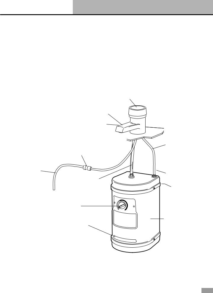
Parts and Features
Cold water supply line from saddle valve
(Page 9)
How your hot water dispenser works
Water is electrically heated to a |
enters the bottom of the tank and |
brewing/cooking hot 190°F (88°C) |
forces hot water out of the faucet. |
by a tank that mounts under the |
The system is vented so the tank is |
sink. A thermostat maintains it at |
not pressurized. |
this approximate temperature. When |
|
you turn the On/Off Cap, cold water |
|
|
|
Use this hot water dispenser |
listed to help you find more detailed |
illustration to help you quickly learn |
information about that feature. |
how to install and use your new hot |
|
water dispenser. Page numbers are |
|
On/Off cap (Pages 6, 7, 9, 10)
Spout
(Pages 6, 7, 11)
Cold water supply
line from spout Quick-connect fitting (Page 8)
(Page 9)
Quick-connect fitting
(Page 8)
Flexible tubing
(Page 8) Mounting bracket located behind tank (Page 7)
Temperature Control (Pages 9, 10)
Tank (Page 7)
Model and serial number label/plate
 Drain plug (Page 11)
3
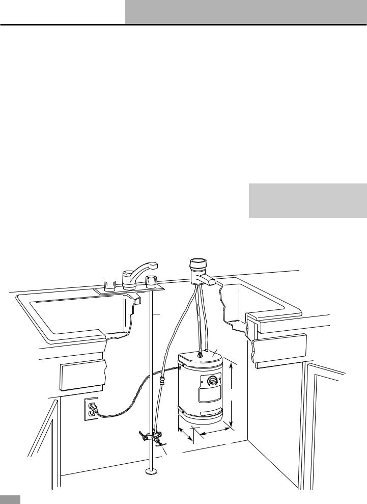
Before You Start
Important: Observe all governing codes and ordinances. 
42" (106.7 cm) max. — electrical outlet to hot water dispenser tank.
Check location where hot water dispenser will be installed. Proper installation is your responsibility. Make sure you have everything necessary for correct installation. It is the responsibility of the installer to comply with installation specifications and with state and local plumbing codes.
Spout requires a 1-1/16" (2.7 cm) to 1-3/8" (3.5 cm) diameter opening in sink or countertop. Spout can be installed in place of sink spray hose. For other installations, contact a qualified installer for best procedure to drill a hole through your type of sink or countertop. Thickness of sink or countertop hole must not exceed 1-1/8" (2.9 cm).
Cold water supply connection must be available. (See “Water supply requirements,” Page 5.)
Grounded electrical outlet is required. (See “Electrical requirements,” Page 5.) The outlet should be located within 42" (106.7 cm) of hot water dispenser tank.
If spout is not to be installed in sink spray hose opening, contact a qualified installer for the best procedure for cutting a spout opening in your type of sink or countertop.
Plumbing connections must comply with all sanitary and plumbing codes.
Do Not store or operate hot water dispenser below 32°F (0°C).
Do Not use pipe sealing compounds. They may get inside dispenser and cause an unpleasant taste or smell.
Water connections use quickconnect fittings which Do Not require sealing compounds to keep them from leaking.
Temperature Control must be turned to “Off” position and the dispenser tank filled before connecting to electrical supply.
This hot water dispenser is Not a water purifier. Some installations may require a water filtering system to improve the quality of water.
Spout installed in spray hose opening in sink.
Cold |
|
water |
|
line |
Tank |
|
|
|
must be |
|
mounted |
|
vertically. |
|
11-1/8" |
|
(28.3 cm) |
5-5/8" |
6-3/4" |
(14.3 cm) |
(17.1 cm) |
Saddle valve
If spout is not to be installed in sink spray hose opening, cut 1-1/16"
(2.7 cm) min. — 1-3/8"
(3.5 cm) max. dia. sink or countertop cutout
1-1/8" (2.9 cm) max. countertop or sink thickness
4

Before You Start cont.
Tools and materials needed
ruler or measuring tape
pliers 


 pencil
gloves
flat-blade screwdriver
safety glasses
tubing cutter
1/4" (6.4 mm) drill bit 
hand or electric drill
open-end wrench(es) fit saddle valve
1/4" (6.4 mm) O.D. copper tubing
bucket or pan
2 mounting bracket screws (and
2 plastic anchors if attaching to  dry wall)
 Saddle valve kit to fit
water supply line
Kit must meet all local codes and ordinances.
Parts supplied
Remove parts from packages. Check that all parts were included.
spout
assembly
gasket
clamp
tank mounting bracket
tank
Electrical requirements
 WARNING
Electrical Shock Hazard
Plug into a grounded 3 prong outlet.
Do not remove ground prong. Do not use an adapter.
Do not use an extension cord.
Failure to follow these instructions can result in death, fire, or electrical shock.
If codes permit and a separate ground wire is used, it is recommended that a qualified electrician determine that the ground path is adequate.
A 120-volt, 60-Hz, AC-only 15or 20ampere fused, grounded electrical supply is required. It is recommended that a separate circuit serving only your hot water dispenser be provided. Use an outlet that cannot be turned on/off by a switch.
Water supply requirements
If local codes permit, the hot water dispenser feed line should be connected to the cold water supply line using a saddle tapping valve.
Important: If local codes Do Not permit the use of saddle valves, special feed valves can be obtained from your local plumbing supply distributor.
Connection to hot water line is not recommended. Energy will be wasted in heating the water twice and the magnesium rod used in household heating may produce a “rotten egg” taste.
3-prong ground-type outlet
3-prong ground plug
ground prong
power supply cord
Recommended ground method
For your personal safety, the hot water dispenser must be grounded. This appliance is equipped with a power supply cord having a 3-prong ground plug. To minimize possible shock hazard, the cord must be plugged into mating, 3-prong, groundtype outlet, grounded in accordance with all national and local codes and ordinances. If a mating outlet is not available, it is the personal responsibility and obligation of the customer to have a properly grounded, 3-prong outlet installed by a qualified electrician.
If this unit is replacing a hot water dispenser connected to a hot water supply, the existing connection may be used.
A water filter is recommended if your water supply contains sand, grit or other particles. If a filter is used, the water pressure to the dispenser should not drop below 20 psi (138 kPa).
5
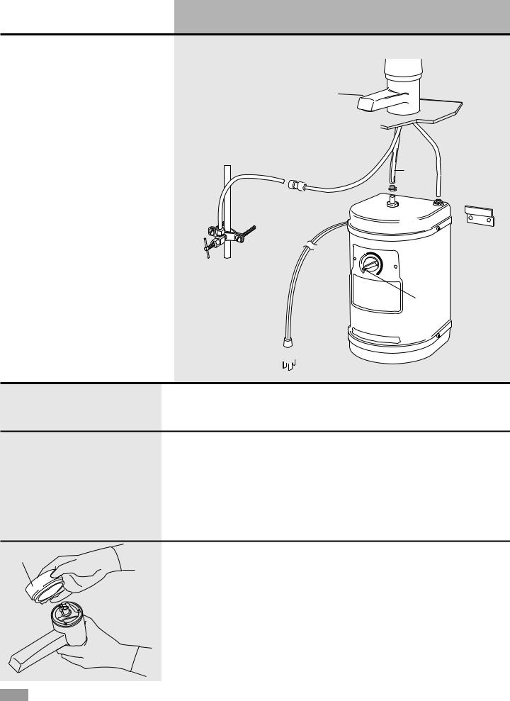
Installation Instructions
3. 6.
Numbers  15.
15.
correspond
2.
to steps.
|
|
4. |
5. |
|
|
|
|
|
|
5. |
|
|
|
|
flexible |
|
|
|
tubing |
|
13. |
|
8. |
13. |
|
9. |
|
|
|
12. |
10. |
7. |
|
||
|
11. |
14. |
|
|
|
|
|
off |
|
|
position |
16.
NOTE: Do NOT plug power supply cord into outlet.
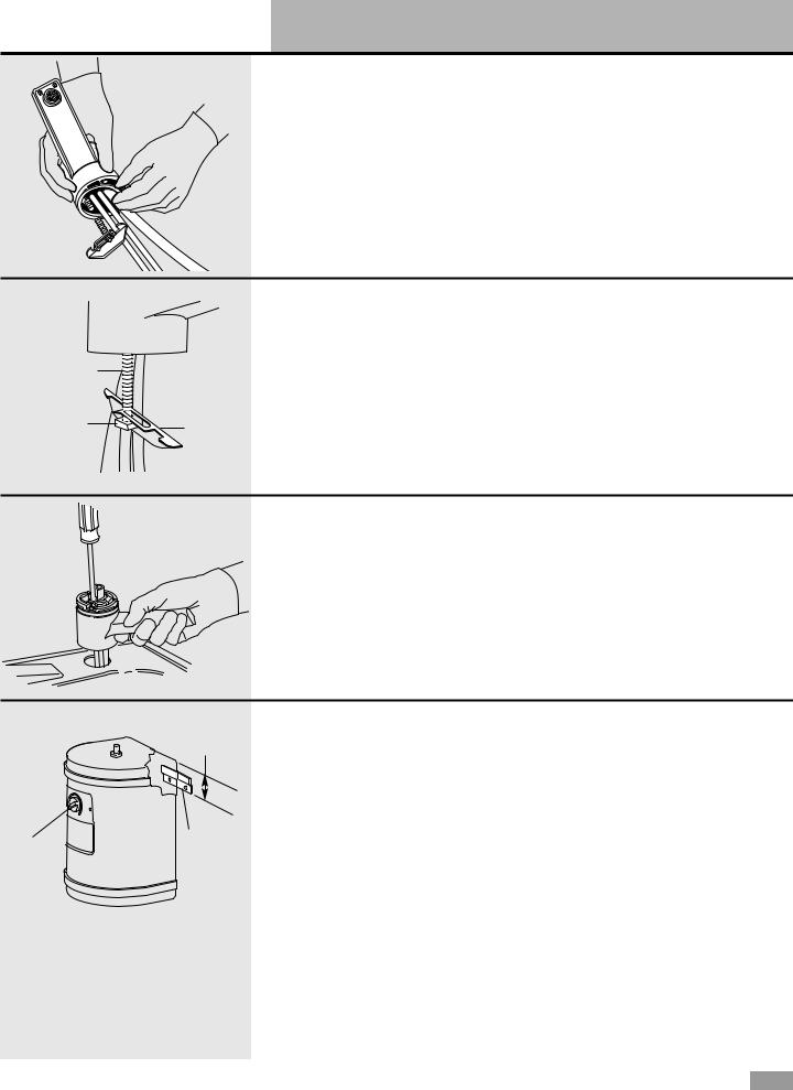
1.Put on gloves and safety glasses.
2.Determine where you will install |
NOTE: It is recommended that only |
your hot water dispenser. Check |
a licensed plumber or professional |
below sink to assure that reinforcing |
installer cut an opening in the sink |
ribs, support brackets or cabinet |
or countertop. |
construction will not interfere with |
|
spout. Knock out plug from hole in |
|
sink or cut a hole in sink or |
|
countertop. |
|
On/Off Cap |
3.Remove masking tape and tag |
|
|
|
from spout assembly. Do Not remove |
|
quick-connect fittings from spout |
|
tubing or tank tubing. Do not |
|
replace quick-connect fittings with |
|
brass fittings. Brass fittings can cause |
|
lead contamination. |
Carefully pull On/Off Cap off the spout assembly and set aside.
6
Installation Instructions cont.
NOTE: Do NOT plug power supply cord into outlet.
4.Lay spout assembly on flat surface with coiled tubing facing up. Using one hand to hold tubing just below spout, carefully straighten
gasket 


tubing with other hand. Slide gasket over tubing so that lip side of gasket is seated into base of spout.
|
5.Loosen square nut until it is |
Hold nut, bracket, gasket and tubing |
|
flush with end of the mounting screw. |
in position and insert into hole in sink |
|
Tip spout bracket against mounting |
or counter. |
mounting |
screw. (Bracket will form a “y” when |
|
screw |
in the correct position.) |
|
square |
bracket |
|
nut |
||
|
6.Pull up on spout body to keep tension on spout mounting bracket and nut. Tighten screw inside the spout until spout is securely in position. Do not overtighten. Snap on On/Off Cap.
off position
2-1/4"
(5.7 cm)
bracket
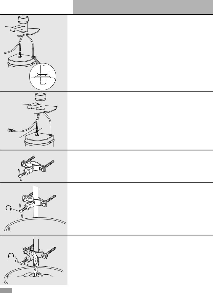
7.Position tank vertically beneath spout so that flexible tubing from spout reaches center stainless tubing on tank, and tank touches wall. Use a pencil to mark on the wall where the top of tank needs to be located. Set tank aside. Mark a second line 2-1/4" (5.7 cm) below the first line.
Note: The tank must be positioned so that the flexible tubing to the faucet does not kink.
Position mounting bracket on wall so that bottom of mounting bracket is even with the lower line. Use two screws (and plastic anchors if attaching to dry wall) to fasten mounting bracket to wall. Hang tank on bracket.
7
Installation Instructions cont.
|
NOTE: Do NOT plug power supply cord into outlet. |
|
|
8.Connect 1/4" (6.4 mm) spout |
NOTE: If you need to remove tubing, |
|
tubing (longer tubing) to the rear |
push down on collet. Pull tubing out |
|
quick-connect fitting on top of tank. |
of quick-connect fitting. |
quick- |
Push tubing straight into fitting as far |
|
as it will go. Pull on tubing. The |
|
|
connect |
tubing should not come out when |
|
fitting |
|
|
|
properly installed. |
|
collet |
Do Not lengthen, twist or tightly |
|
|
bend tubing. |
|
|
9.Connect flexible tubing from |
|
spout to center tank tubing using |
|
clamp. Make sure flexible tubing |
|
does not kink. |
|
The flexible tubing may be shortened |
clamp |
if necessary. |
|
flexible tubing
10.Install saddle valve following kit instructions. If water supply line is not copper, shut off water supply and
drain line. Drill a 1/4" (6.4 mm) hole into water supply line for the saddle valve piercing pin.
closed
open
11.Turn saddle valve handle clockwise until lance pierces soft copper tubing and valve is firmly seated. If the water line is not copper, turn the saddle valve handle clockwise until the valve is firmly seated. The valve is now in the closed position.
Place a bucket under open end of water supply line. Turn on main water supply valve to pressurize cold water line. Check for leaks.
12.Slowly open saddle valve and flush line into bucket to remove any foreign material that may have been trapped in the supply line during saddle valve installation.
Close saddle valve.
8
Installation Instructions cont.
|
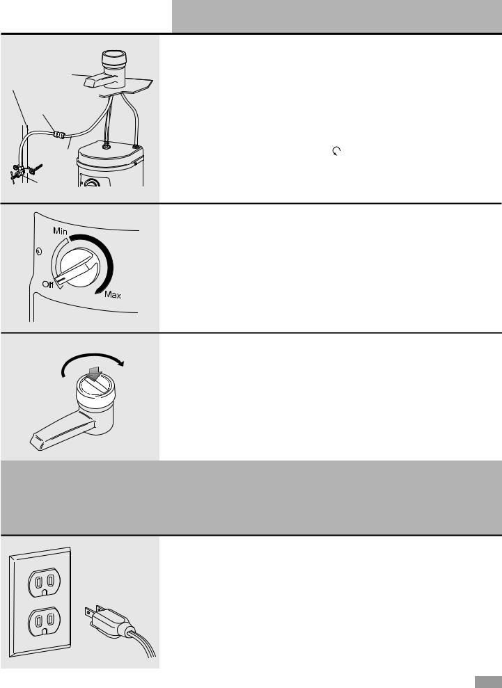
13.Connect water supply line |
NOTE: If you need to remove tubing, |
|
from saddle valve to spout copper |
push down on collet. Pull tubing out |
water supply |
tubing with the factory-assembled |
of quick-connect fitting. |
line |
quick-connect fitting. Push water |
|
quick-connect |
supply line tubing straight into fitting |
|
as far as it will go. Pull on tubing. |
|
|
fitting |
|
|
|
The tubing should not come out |
|
|
when properly installed. Turn the |
|
copper |
saddle valve handle counterclockwise |
|
tubing |
to open water line. |
|
saddle valve
NOTE: Do NOT plug power supply cord into outlet.
14.Turn Temperature Control counterclockwise to “Off” position.
On |
15.Push down and turn the |
|
|
|
On/Off Cap clockwise to open spout. |
|
Hold cap open to fill tank (about 1 |
|
minute). When tank is full, water will |
|
flow from spout. Release cap. |
NOTE: Turn Temperature Control to “Off” position before plugging hot water dispenser into power supply. If tank is empty and thermostat is in an “On” position when the
power supply cord is connected, the heater will overheat causing an unpleasant taste, black specks in the water, and permanent damage to the heater seals.
16.Plug power supply cord into grounded 3-prong outlet.
Turn Temperature Control clockwise to highest position.
Water in tank will reach maximum temperature in approximately
15 minutes.
When water is heating, you may hear gurgling noises coming from the tank. There may also be some spitting or
hot water flow from the faucet. This is normal for the initial heat-up of the dispenser.
Turn Temperature Control to lower temperature setting if you notice vapor or hear boiling noise.
NOTE: Temperature Control controls tank heater, not water delivery. Rotate Temperature Control clockwise to raise water temperature, counterclockwise to
lower water temperature. |
9 |
|
Using Your Hot Water Dispenser
Before using the first time
Check that installation steps 14-16 were completed.
The hot water dispenser can be permanently damaged if these steps are not followed.
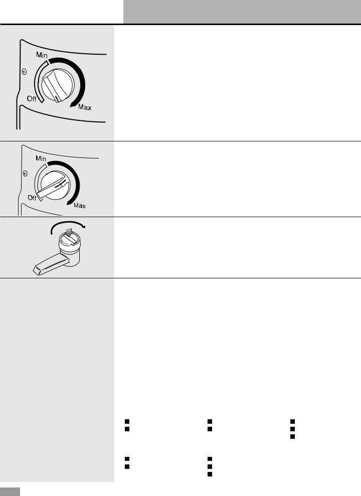
Temperature control
The water temperature is thermostatically controlled. It can be adjusted from “Off” to approximately 190°F (88°C).
To raise or lower the temperature, turn the Temperature Control. The “Max” setting is recommended for
best performance. However, under certain conditions, it is possible for the water to boil when the Temperature Control is set at “Max.” If you see any vapor or hear boiling, turn Temperature Control to lower temperature as necessary.
Dispensing hot water
Push down and turn the On/Off Cap clockwise and hold until desired amount of hot water is obtained. You can control the flow of water by how
far you turn the cap. For maximum flow, turn cap until it stops. Release the On/Off Cap to turn off water.
Hot water dispenser uses
Regardless of what food you are preparing, you’ll appreciate the convenience and time saved by your hot water dispenser. The dispenser allows you to draw the amount of hot
water you require [up to 2 quarts (1.9 liters) at one time]. It eliminates the need to heat a full teakettle for a cup of hot water.
Preparing instant foods and drinks
Instant foods that require only 190°F (88°C) water for complete preparation include:
|
coffee |
|
soup or bouillon |
|
frosting mix |
|
|
|
|||
|
tea |
|
mashed potatoes |
|
|
|
|
|
|
||
|
hot chocolate |
|
instant cereal |
|
|
|
|
|
|
||
|
|
|
|
Cooking shortcuts
190°F (88°C) water will give you a fast start for any food you cook that requires boiling water such as:
packaged dinners
fresh or frozen vegetables
Other uses
loosening jar lids
peeling tomatoes or peaches
10
Loading...