


BUILT-IN GRILL CABINET SIDE BURNER
Installation Instructions and Use & Care Guide
For questions about features, operation/performance, parts, accessories or service, call: 1-877-373-2301 or visit our website at www.kitchenaidgrills.com
Languages spoken: English, Spanish, French 8 a.m.-5 p.m., PST. Monday-Friday.
QUEMADOR LATERAL PARA GABINETE
DE ISLA CONSTRUIDA
Instrucciones de instalación y manual de uso y cuidado
Para consultas respecto a características, funcionamiento, rendimiento, piezas, accesorios o servicio técnico, llame al: 1-877-373-2301 o visite nuestro sitio de internet en www.kitchenaidgrills.com
Lenguages ablados: Ingles, Espanol y Frances de 8 a.m.-5 p.m., PST. Lunes-Viernes.
GRILL ENCASTRÉ DANS LE CABINET AVEC UN BRÛLEUR LATÉRAL
Instructions d’installation et guide d’utilisation et d’entretien
Pour des questions à propos des caractéristiques, du fonctionnement/rendement, des pièces, des accessoires ou du service, |
|
composer le: 1-877-373-2301 |
|
ou visiter notre site web www.kitchenaidgrills.com |
|
Langues parlées: anglais , espagnol, français entre 8 h et 17 h, HNP, du lundi au vendredi. |
|
Table of Contents/Índice/Table des matières................................................................................. |
2 |
Keep this manual for future reference.
Conserve el presente manual para consultas futuras.
Conserver ce manuel à titre de référence ultérieure.
760-0023 (LP) / 770-0023 (NG) |
19000655A1 |

TABLE OF CONTENTS
OUTDOOR BUILT-IN SIDE BURNER SAFETY …….…..........3 |
|
PACKAGE PARTS LIST ....................................................... |
5 |
ASSEMBLY INSTRUCTIONS .…………………....……….……6 |
|
INSTALLATION REQUIREMENTS ………………………....11 |
|
Tools and Parts ……………………….….…….………......…...11 |
|
Location Requirements ……………………………...………12 |
|
Product Dimensions ………………………………..……….…12 |
|
Built-In Outdoor Side Burner Enclosure ….…….…..….……..12 |
|
Cabinet Cutout Dimensions………………….…………………13 |
|
Gas Supply Requirements ……………...………………………14 |
|
Gas Connection Requirements …………………..…..……..…15 |
|
INSTALLATION INSTRUCTIONS………………..............…...16 |
|
Make Gas Connection…………………….............……………16 |
|
GAS CONVERSION ……………………………….............…...18 |
|
Gas Connection to Natural Gas ………………………......…...18 |
|
Tools and Parts for Gas Conversion …………………......…...18 |
|
Conversion from LP Gas to Natural Gas …...…………......….19 |
|
USING YOUR OUTDOOR SIDE BURNER …….............…...21 |
|
Lighting the Side Burner ………….……………………......…...21 |
|
OUTDOOR SIDE BURNER CARE ..….……….………………22 |
|
General Cleaning ………….………….………………......…...22 |
|
TROUBLESHOOTING ........................................................... |
23 |
ASSISTANCE …………………………………………….…..…23 |
|
Accessories………………………………………………...……..23 |
|
WARRANTY ……………………………………….…………….24 |
|
REPLACEMENT PARTS………………………………...….…61 |
|
ÍNDICE
SEGURIDAD DEL QUEMADOR DE USO EXTERIOR .........26 LISTA DE CONTENIDO DEL PAQUETE………………......…..5 INSTRUCCIONES DE ENSAMBLAJE ….………..…..………..6 REQUISITOS DE INSTALACIÓN…………..…………….…....28 Herramientas y piezas ….…….….………………….….……....28 Requisitos de ubicación …………………………….….……....29 Medidas del producto …………………………….……...……..29 Recinto del quemador lateral
para gabinete de isla construida ………………………………29
Dimensiones del corte del armario ………………...................30 Requisitos del suministro de gas …………………..……….31
Requisitos para la conexión de gas……………………..……..32
INSTRUCCIONES DE INSTALACIÓN ………….............…...34 Instalación del Quemador …………………………………..…..34
Conexión del suministro de gas ………..……….…………...34 |
|
CONVERSIONES DE GAS ………………………….......….….36 |
|
Conexión de gas a gas natural ..........................................….36 |
|
Herramientas y piezas para la conversión de gas …………36 |
|
Conversión de gas LP a gas natural ………….…….…………37 |
|
USO DEL QUEMADOR LATERAL …….………..……..…..39 |
|
Encendido del Quemador Latéral ….…………………...……..39 |
|
CUIDADO DEL QUEMADOR PARA EXTERIORES …..……40 |
|
Limpieza general …………..……………………………...……..40 |
|
SOLUCIÓN DE PROBLEMAS................................................ |
41 |
ASISTENCIA…………………………………………..……..…..41 |
|
Accesorios ………………………………………………...……..41 |
|
GARANTÍA ……………………………………………..……......42 |
|
PIEZAS DE REPUESTO …………………………….............…61 |
|
TABLE DES MATIÈRES
SÉCURITÉ DU BRÛLEUR LATERAL ............................... |
44 |
CONVERSIONS POUR CHANGEMENT DE GAZ ……...…..53 |
|
LISTE DES PIÈCES DE L’EMBALLAGE................................ |
5 |
Raccordement du gaz au gaz naturel ………………………....53 |
|
CONSIGNES POUR L’ASSEMBLAGE……………….......……6 |
Outils et pièces pour conversion de gaz ………………..…...53 |
||
EXIGENCES D’INSTALLATION …………………..…….....…46 |
Conversion de gaz propane à gaz naturel …………..…....….54 |
||
Outils et pieces ………………………………………..…………46 |
UTILISATION DU BRÛLEUR LATÉRAL D'EXTÉRIEUR .….56 |
||
Exigences d'emplacement ………………………...…………47 |
Allumage du Brûleur Latéral ……..….…..….….….….……......56 |
||
Dimensions du produit ……………………………………...…..47 |
ENTRETIEN DU BRÛLEUR D’EXTÉRIEUR ….……………..57 |
||
Enceinte du brûleur encastré d'extérieur ………………….….47 |
Nettoyage Général ……...………….………..….….….……......57 |
||
Dimensions de l'ouverture à découper dans le placard …….48 |
DÉPANNAGE.......................................................................... |
58 |
|
Spécifications de l‘alimentation en gaz ……………………….49 |
ASSISTANCE………………………………….…..………….…58 |
||
Exigences concernant le raccordement au gaz …………...…50 |
Accessoires .……………………………………………...……..58 |
||
INSTRUCTIONS D’INSTALLATION …….…………….……...51 |
GARANTIE……………………………………..……..……...…..59 |
||
Installation du brûleur d'extérieur encastré…..………..……...51 |
PIÈCES DE RECHANGE …………………..………………...61 |
||
2

OUTDOOR BUILT-IN SIDE BURNER SAFETY
DANGER
If you smell gas:
1.Shut off gas to the appliance.
2.Extinguish any open flame.
3.Open lid.
4.If odor continues, keep away from the appliance and immediately call your gas supplier or your fire department.
WARNING
1.Do not store or use gasoline or other flammable liquids or vapors in the vicinity of this or any other appliance.
2.An LP cylinder not connected for use shall not be stored in the vicinity of this or any other appliance.
CALIFORNIA RESIDENTS ONLY - WARNING:
This product and the fuels used to operate this product (liquid propane), and the products of combustion of such fuels, can expose you to chemicals including benzene, which is known to the State of California to cause cancer and reproductive harm.
For more information go to: www.P65Warnings.ca.gov.
In the State of Massachusetts, the following installation instructions apply:
Installations and repairs must be performed by a qualified or licensed contractor, plumber, or gasfitter qualified or licensed by the State of Massachusetts.
If using a ball valve, it shall be a T-handle type.
A flexible gas connector, when used, must not exceed 3 feet.
IMPORTANT: This grill is manufactured for outdoor use only. For grills that are to be used at elevations above 2,000 ft (609.6 m) orifice conversion is required. See “Gas Supply Requirements” section. It is the responsibility of the installer to comply with the minimum installation clearances specified on the model/serial rating plate. The model/serial rating plate for freestanding models can be found on the left-hand cabinet door.
3
IMPORTANT SAFETY INSTRUCTIONS
WARNING: To reduce the risk of fire, electrical shock,
Injury to persons, or damage when using the outdoor cooking gas appliance, follow basic precautions, including the following:
Do not install portable or built-in outdoor cooking gas appliances in or on a recreational vehicle, portable trailer, boat or in any other moving installation.
Always maintain minimum clearances from combustible construction, see “ Location Requirements” section.
The outdoor cooking gas appliance shall not be located under overhead unprotected combustible construction.
This outdoor cooking gas appliance shall be used only outdoors and shall not be used in a building, garage, or any other enclosed area.
Keep any electrical supply cord and fuel supply hose away from any heated surfaces.
Keep outdoor cooking gas appliance area clear and free from combustible material, gasoline and other flammable vapors and liquids.
Do not obstruct the flow of combustion and ventilation air. Keep the ventilation openings of the cylinder enclosure free and clear from debris.
Inspect the gas cylinder supply hose before each use of the outdoor cooking gas appliance. If the hose shows excessive abrasion or wear, or is cut, it MUST be replaced before using the outdoor cooking gas appliance. Contact your dealer and use only replacement hoses specified for use with the outdoor cooking gas appliance.
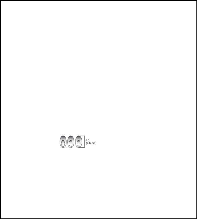
Visually check the burner flames. They should be blue. Slight yellow tipping is normal for
LP gas. The flames should
be approximately 1" (2.5 cm) high.
Check and clean burner/venturi tube for insects and insect nest. A clogged tube can lead to fire under the outdoor cooking gas appliance.
The LP gas supply cylinder to be used must be:
-constructed and marked in accordance with the Specification for LP Gas cylinders of the U.S. Department of Transportation (DOT) or the National Standard of Canada, CAN/CSA-B339, Cylinders, Spheres, and Tubes for Transportation of Dangerous Goods; and Commission.
-provided with a listed overfilling prevention device.
-provided with a cylinder connection device compatible with the connection for outdoor cooking gas appliances.
Always check connections for leaks each time you connect and disconnect the LP gas supply cylinder. See “Installation Instructions” section.
When the outdoor cooking gas appliance is not in use, the gas must be turned off at the supply cylinder.
Storage of an outdoor cooking gas appliance indoors is permissible only if the cylinder is disconnected and removed from the outdoor cooking gas appliance.
Cylinders must be stored outdoors and out of the reach of children and must not be stored in a building, garage, or any other enclosed area.
The pressure regulator and hose assembly supplied with the outdoor cooking gas appliance must be used. A replacement pressure regulator and hose assembly specific to your model is available from your outdoor cooking gas appliance dealer.
Gas cylinder must include a collar to protect the cylinder valve.
For appliances designed to use a CGA791 connection: Place a dust cap on cylinder valve outlet whenever the cylinder is not in use. Only install the type of dust cap on the cylinder va`lve outlet that is provided with the cylinder valve. Other types of caps or plugs may result in leakage of propane.
If the following information is not followed exactly, a fire causing death or serious injury may occur.
Do not store a spare LP gas cylinder under or near this outdoor cooking gas appliance.
Never fill the cylinder beyond 80 percent full.
SAVE THESE INSTRUCTIONS
4

Package Parts List
Lista de contenido del paquete
Liste des pièces de l'emballage
1 |
2 |
x2 |
3 |
4 |
5 |
6 |
7
5

ASSEMBLY INSTRUCTIONS/INSTRUCCIONES DE ENSAMBLAJE/CONSIGNES POUR L’ASSEMBLAGE
Tools Needed / Herramientas necesarias / |
Outillage Requis |
|||||
|
|
|
|
|
|
|
|
Some parts come |
|
Algunas partes |
|
|
Certaines pièces |
|
|
vienen con los |
|
|
sont livrées avec les |
|
|
with Screws pre- |
|
|
|
||
|
|
tornillos pre |
|
|
vis pré-installées. |
|
|
installed. |
|
|
|
||
|
|
instalados. |
|
|
Desserrez et |
|
|
Loosen and tighten |
|
|
|
||
|
|
Afloje y apriete para |
|
|
resserrez pour |
|
|
for final assembly. |
|
|
|
||
|
|
el ensamble final. |
|
|
l'assemblage final. |
|
|
|
|
|
|
||
|
|
|
|
|
|
|
Hardware package list / Lista de piezas / Liste de pièces
Truss Head Screw |
A x5 |
Flat Washer |
B x4 |
|
|
||
Tornillo de cabeza |
|
Arandela plana |
|
de armadura |
|
Rondelle plate |
|
Vis à tête bombée |
|
5/32" |
|
5/32 - 32 x 3/8" |
|
|
|
1.
1
6
2. 2
3. 2
7
4.
5.
3
5
 4
4
8
6.
6
7.
A
9

8.
A
x4
B
x4
7
10
INSTALLATION REQUIREMENTS
Tools and Parts
Gather the required tools and parts before starting installation. Read and follow the instructions provided with any tools listed here.
Configuration: Stand-Alone Side Burner (760-0023)
Tools needed |
|
|
|
|
Tape Measure |
|
Wrench or pliers |
|
Small, flat-blade screwdriver |
|
Pipe wrench |
|
Flat-blade screwdriver |
Scissors or cutting pliers (to remove tiedowns) |
|
#2 and #3 Phillips screwdriver |
|
Noncorrosive leak-detection solution |
|
Level
Parts Supplied for 20 lb LP Gas Installation
Gas pressure regulator/hose assembly set for 11" WCP LP gas
LP gas fuel tank tray
Parts Supplied for Conversion to Natural Gas
1.70 mm Natural gas orifice for side burner (Model 760-0023)
Parts Needed for Conversion to Natural Gas
Natural gas conversion kit (Order Part Number 710-0003). Natural gas conversion kit includes:
Natural gas regulator (marked “Natural Gas Regulator”)
10 ft (3.0 m) PVC flexible gas supply hose with quick connector
6 mm wrench
6 mm nut driver
Hex key
5.9 in. NG regulator hose
Gas line shut off valve
½" male pipe thread nipple for connection to pressure regulator
LP gas-resistant pipe-joint compound
CSA design-certified outdoor flexible stainless steel appliance connector (4-5 ft [1.2-1.5 m]) or rigid gas supply line as needed
11

Location Requirements |
|
Product Dimensions |
5.7“ (14.4cm) |
7.3“ (18.4cm) |
9.1“ (23cm) |
Built-In Outdoor
Side Burner Enclosure
Select a location that provides minimum exposure to wind and traffic paths. The location should be away from strong draft areas.
Do not obstruct flow of combustion and ventilation air. Clearance to combustible construction for burner:
A minimum of 36” (92 cm) must be maintained between the front, sides and back of the burner and any combustible construction.
A 36” (92 cm) minimum clearance must also be maintained below the cooking surface, and the burner shall not be used under overhead combustible construction.
The enclosure for the built-in outdoor side burner is to be a minimum of 7.3" (18.4 cm) high x 16.8" (42.6 cm) deep x 11.5" (29.2 cm) wide.
This built-in outdoor side burner is only for installation in a built-in enclosure constructed only of non-combustible materials. Non-combustible materials could be brick, firewall or steel. Do not use wood or other combustible materials for built-in enclosure.
12

Cabinet Cutout Dimensions
The illustration below includes cutout dimensions and minimum spacing requirements. The illustration is for reference. The design of your cabinet layout can be personalized, but the dimensions for the cutouts and minimum spacing must be followed.
Counter or support surfaces must be level.
The installation of this side burner must conform with local codes or, in the absence of local codes, with either the National Fuel Gas Code, ANSI Z223.1/NPFA 54, Natural Gas and Propane Installation Code, CSA B149.1, or Propane Storage and Handling Code, B149.2.
NOTE: The outdoor side buner drops into the enclosure opening and is supported by its side flanges. Do not use a bottom support.
Built-in Outdoor Side Burner Enclosure Ventilation for LP Gas
Any enclosure is to be ventilated by openings at both the top |
|
The island must be vented in one of the 2 following ways: |
and lower levels of the enclosure. The following information is |
|
A 90°or a 180°ventilation in the island to ensure that air |
the minimum for proper ventilation of your island construction. |
|
flows through the island at either 90°or 180°. |
|
|
Any enclosure for built-in installation is to have at least |
There should be a minimum of 1 7/8" (4.4 cm) of |
|
one ventilation opening on an exposed exterior side |
clearance from the bottom of the main burner bowl |
|
located within 2½" (6.0 cm) of the top and is to be a |
assembly island for proper ventilation. |
|
minimum of 20 in.2 (129.0 cm2). One ventilation opening |
NOTE: There should be no solid surface underneath the |
|
within 1½" (3.0 cm) of the bottom of the enclosure, and |
firebox portion of the side burner. |
|
the bottom opening is to be a minimum of 10 in.2 (64.5 |
A minimum of 3" (7.6 cm) is required between the back |
|
cm2). All vent openings are to be unobstructed. Every |
of the side burner and any noncombustible materials. A |
|
opening is to be a minimum of 1/8" (0.32 cm) wide. |
minimum of 36" (92 cm) is required between the back of |
|
|
the side burner and any combustible material. |
|
|
13
To ensure that the side burner operates properly, it is recommended that the island have ventilation on all 4 sides as shown in the following illustration. The ventilation holes should be as diagrammed to ensure adequate ventilation for your side burner and island.
Proper ventilation is a required based on the above mentioned specifications for your side burner to operate properly.
Gas Supply Requirements
Observe all governing codes and ordinances.
IMPORTANT: This installation must conform with all local codes and ordinances. In the absence of local codes, installation must conform with American National Standard, National Fuel Gas Code ANSI Z223.1 - latest edition or CAN/CGA B149.1 – latest edition.
IMPORTANT: The side burner must be connected to a regulated gas supply.
Refer to the model/serial rating plate for information on the type of gas that can be used. If this information does not agree with the type of gas available, check with your local gas supplier.
Gas Conversion:
No attempt shall be made to convert the side burner from the gas specified on the model/serial rating plate for use with a different gas type without consulting the serving gas supplier. The conversion kit supplied with side burner must be used. See “Gas Conversions” section for instructions.
Gas Pressure Regulator
A gas pressure regulator with the following pressure settings must be used with the side burner. The inlet (supply) pressure to the regulator should be as follows for proper operation:
LP Gas:
Operating pressure: 11" (27.9 cm) WCP
Inlet (supply) pressure: 11" to 14" (27.9 cm to 35.5 cm) WCP
Natural Gas:
Operating pressure: 4" (10.2 cm) WCP
Inlet (supply) pressure: 7" to 14" (17.8 cm to 35.5 cm) WCP maximum.
Contact local gas supplier if you are not sure about the inlet (supply) pressure.
14
Burner Requirements for High Altitude
Input ratings shown on the model/serial rating plate are for elevations up to 2,000 ft. (609.6 m).
For elevations above 2,000 ft. (609.6 m), ratings are reduced at a rate of 4% for each 1,000 ft. (304.8 m) above sea level. Orifice conversion is required. See “Assistance” section to order.
Gas Supply Line Pressure Testing
Testing above 1/2 psi (3.5 kPa) or 14" (35.5 cm) WCP (gauge):
The side burner and its individual shutoff valve must be disconnected from the gas supply piping system during any pressure testing of that system at test pressures greater than 1/2 psi (3.5 kPa).
Testing below 1/2 psi (3.5 kPa) or 14" (35.5 cm) WCP (gauge) or lower:
The side burner must be isolated from the gas supply piping system by closing its individual manual shutoff valve during any pressure testing of the gas supply piping system at test pressures equal to or less than 1/2 psi (3.5 kPa).
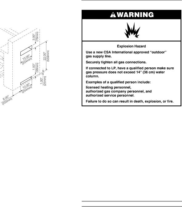
Gas Connection Requirements
This side burner is equipped for use with a 20 lb LP gas fuel tank (fuel tank not supplied). A gas pressure regulator/hose assembly is supplied.
A
A.Gas pressure regulator/hose assembly
It is also design-certified by CSA International for local LP gas supply or for Natural gas with appropriate conversion.
20 lb LP Gas Fuel Tank
The 20 lb LP gas fuel tank must be mounted and secured.
1.Open cabinet doors (if applicable).
2.Loosen the tank tray locking screw.
3.Place the 20 lb LP gas fuel tank bottom collar into the mounting hole in the tank tray.
4.Tighten the locking screw against the bottom collar of the 20 lb LP gas fuel tank to secure.
5.Close cabinet doors (if applicable).
B
A C
A.Locking screw
B.Tank tray
C.20 lb LP gas fuel tank tray
Make sure the tank is firmly secured in an upright position.
LP Gas Conversion Using a Local LP Gas Supply
If you want to convert to local LP gas supply, contact your local gas company for specific instructions.
Natural Gas Conversion
Conversion must be made by a qualified gas technician. The qualified Natural gas technician shall provide the Natural gas supply to the selected side burner location in accordance with the National Fuel Gas Code ANSI Z223.1/NFPA 54 - latest edition, and local codes. For conversion to Natural gas, the Natural Gas Conversion Kit supplied with the side burner must be used. See the “Gas Conversions” section.
IMPORTANT: The gas installation must conform with local codes, or in the absence of local codes, with the National Fuel Gas Code, ANSI Z223.1/NFPA 54 - latest edition.
The gas supply line shall be equipped with an approved shutoff valve. This valve should be located in the same area as the side burner and should be in a location that allows ease of opening and closing. Do not block access to the shutoff valve. The valve is for turning on or shutting off gas to the side burner.
A.Gas supply line
B.Shutoff valve “open” position
C.To side burner
15

INSTALLATION INSTRUCTIONS
Built-in Outdoor Side Burner
Installation
Unpack side burner. Remove all packaging materials and remove side burner from carton.
Place side burner into outdoor enclosure, but leave enough room in back to connect to gas supply.
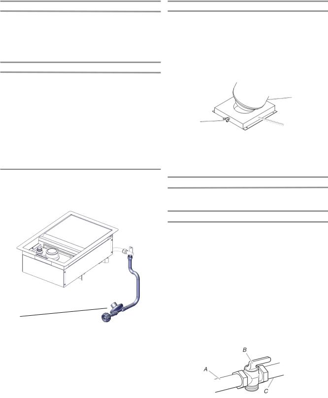
Install 20 lb LP Gas Fuel Tank Tray
The tank tray should be secured to a fixed location that can be easily accessed and will allow the gas pressure regulator/ hose assembly to connect to the 20 lb LP gas fuel tank without kinking or putting strain on the gas pressure regulator/ hose assembly.
1.Place the tank tray in a location that can be secured using 4 screws (supplied) through the predrilled holes.
2.Use 4 screws to secure the tank tray. The typical location for a 20 lb LP gas fuel tank is within the enclosure where the tank can be turned on and off easily.
A.Four5/32-32x3/8” trussheadscrews
NOTE: A bracket or shelf (not supplied) that is large enough to keep a second 20 lb LP gas fuel tank from being stored in the storage area under the side burner is required to be mounted inside the island.
Make Gas Connection
NOTE: If side burner is to be converted to Natural gas, follow instructions in the “Gas Conversions” section.
20 lb LP Gas Fuel Tank
IMPORTANT: A 20 lb LP gas fuel tank must be purchased separately.
IMPORTANT: The 20 lb LP gas fuel tank must be mounted and secured.
IMPORTANT: The gas pressure regulator/hose assembly supplied with the burner must be used. Replacement gas pressure regulator/hose assembly specific to your model is available from your outdoor grill dealer.
To Connect the 20 lb LP Gas Fuel Tank:
1.Check that the 20 lb LP gas fuel tank is in the “OFF” position. If not, turn the valve clockwise until it stops.
2.Check that the 20 lb LP gas fuel tank valve has the proper type-1 external male thread connections per ANSI Z21.81.
3.Check that the burner control knobs are in the “OFF” position.
4.Remove any debris and inspect the valve connections, port, and gas pressure regulator/hose assembly for damage.
NOTE: Always keep the LP cylinder at 90°(upright) orientation to provide vapor withdrawal.
16

A 
 B
B
A.Gas pressure regulator/hose assembly
B.20 lb LP gas fuel tank
5.Using your hand, turn the gas pressure regulator/hose assembly clockwise to connect to the 20 lb LP gas fuel tank as shown.
Hand tighten only. Use of a wrench could damage the quick coupling nut.
A.Gas pressure regulator/hose assembly
B.20 lb LP gas fuel tank
Make sure that the cylinder valve connection device properly mates with the connection device attached to the inlet of the pressure regulator.
6.Open the tank valve fully by turning the valve counterclockwise. Wait a few minutes for gas to move through the gas line.
7.Before lighting the side burner, test all connections by brushing on an approved noncorrosive leak-detection solution. Bubbles will show a leak.
8.If a leak is found, turn the tank valve off and do not use the side burner. Contact a qualified gas technician to make repairs.
To Disconnect the 20 lb LP Gas Fuel Tank:
1.Check that the burner control knobs are in the “OFF” position and the side burner is cool.
2.Check that the 20 lb LP gas fuel tank is in the “OFF” position. If not, turn the valve clockwise until it stops.
3.Using your hand, turn the gas pressure regulator/hose assembly counterclockwise to disconnect to the 20 lb LP gas fuel tank as shown.
Hand loosen only. Use of a wrench could damage the quick coupling nut.
A.Gas pressure regulator/hose assembly
B.20 lb LP gas fuel tank
4.Place dust cap on cylinder valve outlet whenever the cylinder is not in use. Only install the type of dust cap on the valve outlet that is provided with the cylinder valve. Other types of caps or plugs may result in leakage of propane.
17

GAS CONVERSIONS
Gas Connection to Natural Gas
This installation must conform with local codes and ordinances. In the absence of local codes, installations must conform with either the National Fuel Gas Code ANSI Z223.1 - latest edition, or CAN/CGAB149.1 Natural Gas and Propane installation code.
Copies of the standards listed above may be obtained from:
CSA International
8501 East Pleasant Valley Rd.
Cleveland, Ohio 44131-5575
National Fire Protection Association
One Batterymarch Park
Quincy, Massachusetts 02269
Tools and Parts for Gas Conversion
Gather the required tools and parts before starting installation. Read and follow the instructions provided with any tools listed here.
Tools needed
6mm
Parts supplied
Natural gas orifices
Parts needed
Natural gas conversion kit Part Number 710-0003. See “Assistance” section to order. The conversion kit includes:
Natural gas regulator 4" W.C. (marked “Natural Gas Regulator”)
10 ft (3.0 m) Natural gas hose with quick connector
5.9" (150 mm) Natural gas regulator hose
6 mm nut driver
6 mm wrench
Hex key
IMPORTANT: Gas conversions must be done by a qualified installer. Before proceeding with conversion, shut off the gas supply to the side burner.
18

Conversion from LP Gas to
Natural Gas
Orifice Change and the Installation of the NG regulator
1.Turn off the main gas supply valve.
2.Disconnect 20 lb LP gas fuel tank (if present).
3.Turn off burner control valve.
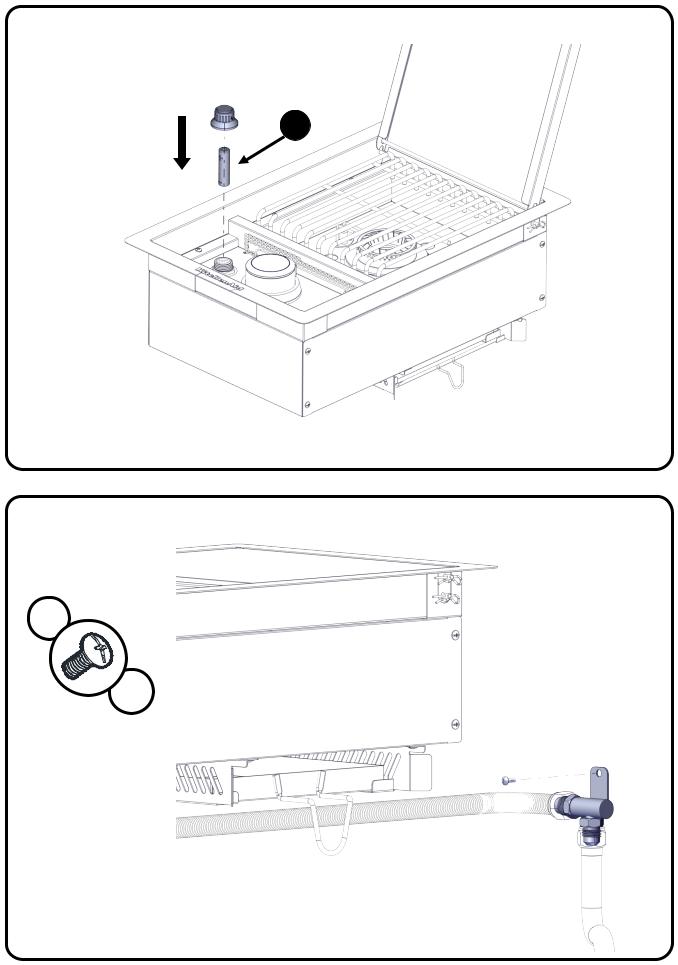
4.Use screwdriver to remove screw holding the corrugated pipe connector to the enclosure.
5.Use adjustable wrench to remove hose and regulator from corrugated pipe connector.
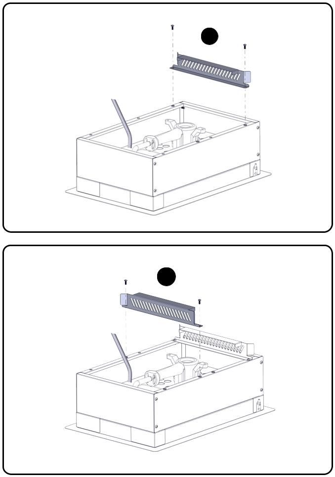
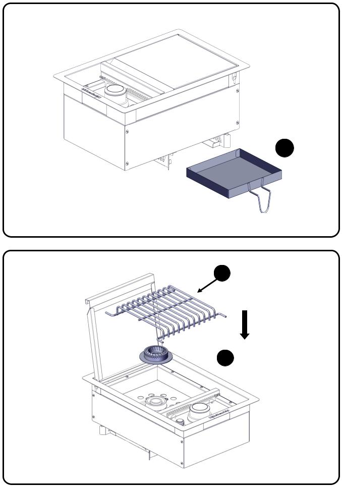
6.Remove side burner cooking grid and burner cover.
7.Remove igniter junction wire from electronic igniter module.
8.Remove 3 screws off the front baffle.
9.Lift up front baffle away from burner.
10.Use a 6 mm socket and wrench or 6 mm nut driver to remove the LP gas orifice from the end of gas valve.
11.Use a 6 mm socket and wrench or 6 mm nut driver to install NG gas orifice to the end of gas valve.
19

12.Reinstall front baffle to burner.
IMPORTANT: Check that the orifice is properly installed inside of the side burner gas valve.
13. Install the 3 screws.
14. Insert igniter junction wire from electronic igniter module.
15. Replace side burner cooking grid and burner cover.
16.Use an adjustable wrench to install Natural gas pressure regulator and corrugated pipe to the corrugated pipe connector.
17.Connect the brass connector on one end of the 10 ft (3.0 m) PVC flexible gas supply hose to the Natural gas pressure regulator (A).
A
18.Connect the quick connector on the other end of the 10 ft (3.0 m) PVC flexible gas supply hose to the rigid Natural gas supply pipe (B).
B
19.Use screwdriver to install screw to hold the corrugate connector to the enclosure.
Record Conversion
The LP appliance nameplate is located on the front side of the burner firebox. Once converted, place the NG appliance nameplate over the current LP appliance nameplate.
In the last page of the Use and Care Guide, write “Converted to Natural Gas”. Also record the conversion date and the technician/company that performed the conversion.
20
 Loading...