

Page 1
Dedicated Communication Unit
DANG ER
WARNING
CAUTION
Note
TIPS
CAUTION
96M13456
Main unit Instruction manual
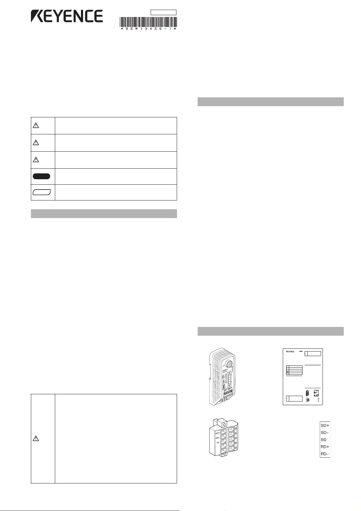
Connector for the RS-422A/485 Label for the connectors
(used when wiring RS-422A)
For 422 connector
1
E N-R4-IM
Dedicated Communication Unit
RS-422A/485 Output Type
N-R4
Instruction Manual
■General precautions
•
At startup and during operation, be sure to check that the
functions and performance of the N-R4 is operating properly.
•
We recommend that you take substantial safety measures to
avoid any damage in the event a problem occurs.
•
If the N-R4 is modified or used in any way other than described in
the specifications, its function and performance cannot be
guaranteed.
•
When the N-R4 is used in combination with other instruments, the
function and performance may be effected by operating conditions
and the surrounding environment.
•
Do not use the N-R4 for the purpose of protecting the human
body.
•
The information contained in this manual is subject to change
without notice.
■Notice
When this product is used under the circumstances and operating
environments described below, adhere to the limitations of the ratings,
take adequate measures to ensure safety such as fail-safe installations
and consult a KEYENCE sales representative.
•
For use under circumstances or environments which are not
described in the manual
•
For use with nuclear power control, railway, aircraft, vehicles,
incinerators, medical equipment, entertainment equipment, safety
devices etc.
•
For use in applications where death or serious property damage is
possible and extensive safety precautions are required.
■For properly using the product
Do not install the N-R4 in the following locations:
•
Locations subject to direct sunlight
•
Locations where the surrounding air temperature is outside the
range of 0 to +50qC or locations subject to condensation as the
result of severe changes in temperature
•
Locations where the ambient humidity is outside the range of 35
to 85%RH.
•
Locations subject to corrosive or flammable gases
•
Locations subject to dust, salts, iron dust, or oil smoke
•
Locations subject to shock or vibration
•
Locations subject to exposure of water, oil, or chemicals
•
Locations where strong magnetic or electric fields are generated
■UL certification
The N-R4 complies with the following UL/CSA standards and has
obtained the UL/C-UL certification.
•
Applicable standards UL508, UL60950-1
•
UL File No. E207185, E167973
•
UL category NRAQ/NRAQ7, NWGQ2/NWGQ8
Be sure to observe the following installation and environment conditions.
•
Pollution degree 2
•
Overvoltage category I
Caution - Do not connect directly to the branch circuit. This product must
be supplied power by a suitable, approved isolated transformer or power
supply not exceeding 200 VA max.
■FCC regulations
The N-R4 complies with the following FCC EMI regulations.
•
FCC Part 15 Subpart B, Class B digital device
■Canada IC (Industry Canada) regulations
The N-R4 complies with the following IC EMI regulations.
•
ICES-003, Class B digital apparatus
■CE marking
The N-R4 complies with the following essential requirements of the EU
Directive.
•
EMC Directive (2004/108/EC)
The following harmonized standards are applied to this product in order
to confirm the compliance.
•
Applicable standards (EMI) EN55011, Class A
EN55022, Class B
•
Applicable standards (EMS) EN61000-6-2
EN61000-6-1
*The length of the communication and power cables should be less than 30 m.
DANGER
Failure to follow these instructions may lead to death or
serious injury.
WARNING
Failure to follow these instructions may lead to injury.
CAUTION
Failure to follow these instructions may lead to product
damage (product malfunction, etc.).
Note
Provides additional information on proper operation.
TIPS
Indicates useful information or information that aids
understanding of text descriptions.
For Safely Using the Product
CAUTION
•
Do not use the N-R4 in an environment subject to
flammable, explosive, or corrosive gases.
•Be sure that all screws are tightened securely.
•Use crimp contacts of the specified size for wiring.
•The N-R4 uses a 24 VDC power supply. Using a power
supply outside this range or an AC power supply may
cause product failure.
•
Do not disassemble or modify the N-R4. This may cause
product failure.
96M00269
CAUTION
•Locate the cables as far as possible from high-voltage
lines and power lines. Otherwise, generated noise may
cause product failure or malfunctions.
•The N-R4 is a precision instrument. If the unit is
dropped or shock is applied, it may be damaged. Use
caution when unpacking, carrying, and mounting.
•Be sure to observe all warnings, cautions, and
precautions specified in the manual.
Foreign Regulations and Standards
Package Contents List
Main unit Instruction manual
Connector for the RS-422A/485 Label for the connectors
(used when wiring RS-422A)
For 422 connector
1
E N-R4-IM
Dedicated Communication Unit
RS-422A/485 Output Type
N-R4
Instruction Manual
■General precautions
•At startup and during operation, be sure to check that the
functions and performance of the N-R4 is operating properly.
•We recommend that you take substantial safety measures to
avoid any damage in the event a problem occurs.
•If the N-R4 is modified or used in any way other than described in
the specifications, its function and performance cannot be
guaranteed.
•When the N-R4 is used in combination with other instruments, the
function and performance may be effected by operating conditions
and the surrounding environment.
•Do not use the N-R4 for the purpose of protecting the human
body.
•The information contained in this manual is subject to change
without notice.
■Notice
When this product is used under the circumstances and operating
environments described below, adhere to the limitations of the ratings,
take adequate measures to ensure safety such as fail-safe installations
and consult a KEYENCE sales representative.
•For use under circumstances or environments which are not
described in the manual
•For use with nuclear power control, railway, aircraft, vehicles,
incinerators, medical equipment, entertainment equipment, safety
devices etc.
•For use in applications where death or serious property damage is
possible and extensive safety precautions are required.
■For properly using the product
Do not install the N-R4 in the following locations:
•Locations subject to direct sunlight
•Locations where the surrounding air temperature is outside the
range of 0 to +50qC or locations subject to condensation as the
result of severe changes in temperature
•Locations where the ambient humidity is outside the range of 35
to 85%RH.
•Locations subject to corrosive or flammable gases
•Locations subject to dust, salts, iron dust, or oil smoke
•Locations subject to shock or vibration
•Locations subject to exposure of water, oil, or chemicals
•Locations where strong magnetic or electric fields are generated
■UL certification
The N-R4 complies with the following UL/CSA standards and has
obtained the UL/C-UL certification.
•Applicable standardsUL508, UL60950-1
•UL File No. E207185, E167973
•UL categoryNRAQ/NRAQ7, NWGQ2/NWGQ8
Be sure to observe the following installation and environment conditions.
•Pollution degree 2
•Overvoltage category I
Caution - Do not connect directly to the branch circuit. This product must
be supplied power by a suitable, approved isolated transformer or power
supply not exceeding 200 VA max.
■FCC regulations
The N-R4 complies with the following FCC EMI regulations.
•FCC Part 15 Subpart B, Class B digital device
■Canada IC (Industry Canada) regulations
The N-R4 complies with the following IC EMI regulations.
•ICES-003, Class B digital apparatus
■CE marking
The N-R4 complies with the following essential requirements of the EU
Directive.
•EMC Directive (2004/108/EC)
The following harmonized standards are applied to this product in order
to confirm the compliance.
•Applicable standards (EMI)EN55011, Class A
EN55022, Class B
•Applicable standards (EMS)EN61000-6-2
EN61000-6-1
*The length of the communication and power cables should be less than 30 m.
Failure to follow these instructions may lead to death or
serious injury.
Failure to follow these instructions may lead to injury.
Failure to follow these instructions may lead to product
damage (product malfunction, etc.).
Provides additional information on proper operation.
Indicates useful information or information that aids
understanding of text descriptions.
For Safely Using the Product
•
Do not use the N-R4 in an environment subject to
flammable, explosive, or corrosive gases.
•Be sure that all screws are tightened securely.
•Use crimp contacts of the specified size for wiring.
•The N-R4 uses a 24 VDC power supply. Using a power
supply outside this range or an AC power supply may
cause product failure.
•
Do not disassemble or modify the N-R4. This may cause
product failure.
96M00269
CAUTION
•Locate the cables as far as possible from high-voltage
lines and power lines. Otherwise, generated noise may
cause product failure or malfunctions.
•The N-R4 is a precision instrument. If the unit is
dropped or shock is applied, it may be damaged. Use
caution when unpacking, carrying, and mounting.
•Be sure to observe all warnings, cautions, and
precautions specified in the manual.
Foreign Regulations and Standards
Package Contents List
Main unit Instruction manual
Connector for the RS-422A/485Label for the connectors
(used when wiring RS-422A)
For 422 connector
RS-422A/485 Output Type
N-R4
Instruction Manual
Failure to follow these instructions may lead to death or
serious injury.
Failure to follow these instructions may lead to injury.
Failure to follow these instructions may lead to product
damage (product malfunction, etc.).
Provides additional information on proper operation.
Indicates useful information or information that aids
understanding of text descriptions.
For Safely Using the Product
■ General precautions
• At startup and during operation, be sure to check that the
functions and performance of the N-R4 is operating properly.
• We recommend that you take substantial safety measures to
avoid any damage in the event a problem occurs.
• If the N-R4 is modified or used in any way other than described in
the specifications, its function and performance cannot be
guaranteed.
• When the N-R4 is used in combination with other instruments, the
function and performance may be effected by operating conditions
and the surrounding environment.
• Do not use the N-R4 for the purpose of protecting the human
body.
• The information contained in this manual is subject to change
without notice.
■ Notice
When this product is used under the circumstances and operating
environments described below, adhere to the limitations of the ratings,
take adequate measures to ensure safety such as fail-safe installations
and consult a KEYENCE sales representative.
• For use under circumstances or environments which are not
described in the manual
• For use with nuclear power control, railway, aircraft, vehicles,
incinerators, medical equipment, entertainment equipment, safety
devices etc.
• For use in applications where death or serious property damage is
possible and extensive safety precautions are required.
■ For properly using the product
•
Do not use the N-R4 in an environment subject to
flammable, explosive, or corrosive gases.
• Be sure that all screws are tightened securely.
• Use crimp contacts of the specified size for wiring.
• The N-R4 uses a 24 VDC power supply. Using a power
supply outside this range or an AC power supply may
cause product failure.
•
Do not disassemble or modify the N-R4. This may cause
product failure.
• Locate the cables as far as possible from high-voltage
lines and power lines. Otherwise, generated noise may
cause product failure or malfunctions.
• The N-R4 is a precision instrument. If the unit is
dropped or shock is applied, it may be damaged. Use
caution when unpacking, carrying, and mounting.
• Be sure to observe all warnings, cautions, and
precautions specified in the manual.
Do not install the N-R4 in the following locations:
• Locations subject to direct sunlight
• Locations where the surrounding air temperature is outside the
range of 0 to +50°C or locations subject to condensation as the
result of severe changes in temperature
• Locations where the ambient humidity is outside the range of 35
to 85%RH.
• Locations subject to corrosive or flammable gases
• Locations subject to dust, salts, iron dust, or oil smoke
• Locations subject to shock or vibration
• Locations subject to exposure of water, oil, or chemicals
• Locations where strong magnetic or electric fields are generated
Foreign Regulations and Standards
■ UL certification
The N-R4 complies with the following UL/CSA standards and has
obtained the UL/C-UL certification.
• Applicable standards UL508, UL60950-1
• UL File No. E207185, E167973
• UL category NRAQ/NRAQ7, NWGQ2/NWGQ8
Be sure to observe the following installation and environment conditions.
• Pollution degree 2
• Overvoltage category I
Caution - Do not connect directly to the branch circuit. This product must
be supplied power by a suitable, approved isolated transformer or power
supply not exceeding 200 VA max.
Attention - Ne raccordez pas l'unité directement au circuit de dérivation.
Ce produit doit être alimenté par un transformateur adapté, isolé et
approuvé ou une alimentation ne dépassant pas 200 VA.
■ FCC regulations
The N-R4 complies with the following FCC EMI regulations.
• FCC Part 15 Subpart B, Class B digital device
■ Canada IC (Industry Canada) regulations
The N-R4 complies with the following IC EMI regulations.
• ICES-003, Class B digital apparatus
■ CE marking
The N-R4 complies with the following essential requirements of the EU
Directive.
• EMC Directive (2004/108/EC)
The following harmonized standards are applied to this product in order
to confirm the compliance.
• Applicable standards (EMI) EN55011, Class A
EN55022, Class B
• Applicable standards (EMS) EN61000-6-2
EN61000-6-1
* The length of the communication and power cables should be less than 30 m.
Package Contents List
DANGER
WARNING
CAUTION
Note
TIPS
CAUTION
1
E N-R4-IM
Page 2
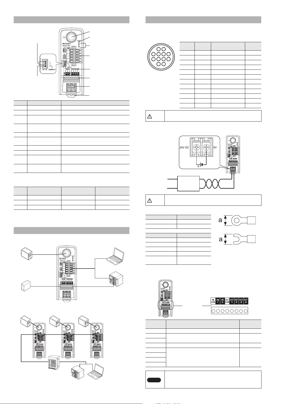
Part Names and Functions
8. DIN rail mounting tab
1. Head port
2. Power LED
3. Communication
status LED
4. RS-422A/485
connector
5. I/O status LED
6. I/O terminals
7. Power terminal
9. RS-422A/485
changeover switch
10. Terminating
resistance switch
KV-B16XC
Head port
OUT1 to 4IN1
Head
BL Series
SR Series
Personal
computer
Timing sensor
RS-422A
or RS-485
RS-232C
RS-485
Personal
computer
PLC
RS-485 master unit
N-410
Head (BL Series, SR Series)
CAUTION
CAUTION
Note
Round 12-pin jack
Power supply
24V+10%
-
20%
Twist pair cable
I/O terminal
block
Number Name Function
1 Head port Used to connect the head.
2 Power LED Lights when the power is ON.
Communication status
3
4
5 I/O status LED Monitors the ON/OFF status of I/O terminals.
6 I/O terminals
7 Power terminal Terminal for 24V DC power supply input.
8 DIN rail mounting tab A tab for mounting the DIN rail.
9
10
LED
RS-422A/485
connector
RS-422A/485
changeover switch
Terminating resistance
switch
Monitors the status of communication with the
head.
Used to connect to the host (personal
computer, PLC).
Used to connect I/O signal lines of control
units.
Used to switch between RS-422A and 485
communications.
Used to switch between ON and OFF of the
terminating resistance.
• States of RS-422A/485 changeover switch and terminating
resistance switch
Number
1 Left Right
2 Left Right
3
RS-422A
communication mode
--
* The factory setting is RS-485 communication mode and terminating
resistance OFF.
RS-485
communication mode
Terminating
resistance ON
-
-
Right
System Configuration Figure
■ When connecting RS-422A or RS-485 (1:1 connection)
Connection and Wiring Methods
■ Connecting the code reader
Connect the code reader to the head port of the N-R4.
Pin layout of the head port
12
6
10
37485
9
1112
Install and remove connection cables with the power
disconnected.
Pin
number
Name Signal name
1 OUT1 OUT1 input Input
2 OUT2 OUT2 input Input
3 RXD RS-232C Receive Input
4 RTS RS-232C Receivable Output
5 OUT4 OUT4 input Input
6 IN2 IN2 output Output
7 TXD RS-232C Transmit Output
8 CTS RS-232C Transmittable Input
9 OUT3 OUT3 input Input
10 IN1 IN1 output Output
11 +5V +5V power supply Output
12 GND(SG) Common GND
Signal
direction
-
■ Connecting the power supply
Connect the 24 VDC power supply to the power terminal of the N-R4.
Using a power supply other than 24 VDC may cause
product failure.
The dimensions of crimp contacts used for wiring should be as follows:
Terminal Dimensions
Round Terminal a: 6 mm Max.
Y terminal a: 6 mm Max.
Item Description
Wire size AWG14-22
Tightening torque 0.49 N·m (4.34 lbf·in)
Wire material Copper
Wire type Stranded wire
Electric wire
temperature rating
+60°C max.
■ Layout and Wiring of the I/O Terminal Block
• Layout of the I/O terminal block
■ RS-485 connection (multi-drop connection)
* At the end of the RS-485 trunk line, set the terminator to ON.
E N-R4-IM
Symbol Description
INCOM Common for IN terminal
IN1
Used as an input terminal for the code reader. Input
IN2
OUTCOM Common for OUT terminal
OUT1
OUT2
OUT3
OUT4
Used as an output terminal from the code reader. Output
Signal
direction
-
-
• For connection, use stranded copper wire having a
gage of AWG16 to 26 and temperature rating of 60°C
or higher.
• The tightening torque is 0.19 N·m (1.7 lbf·in).
2
Page 3

• Wiring IN1 and IN2
Note
Note
Note
Circuit diagram
IN1, IN2
INCOM
Internal
circuit
OUT1 to 4
OUT
COM
Load
Circuit diagram
Load
Load
Load
Load
Internal circuit
External equipment
N-R4
Recommended RS-422A cable (with shield)
Manufacturer: NIHON ELECTRIC WIRE & CABLE Co., LTD
Product name:Instrumentation cable
Model: KNPEV-SB 0.75 mm
2
x 2P
N-R4
Recommended RS-485 cable (with shield)
Manufacturer: NIHON ELECTRIC WIRE & CABLE Co., LTD
Product name:Instrumentation cable
Model: KNPEV-SB (1P) 0.75 mm
2
N-R4 N-R4
Sheath
About 70 mm
Contraction tube
About 40 mm
Shield stranded wire
Insulated wire
About 8 mm
2 mm or less
Top
Bottom
80 mm or more
from the front
80 mm
50 mm
50 mm
• Wiring OUT1 to 4
■ Wiring the RS-422A/485 connector
• Layout of RS-422A pins
Symbol Description Signal direction
SD+ Data transmission + side Output
SD– Data transmission – side Output
SG Signal ground
RD+ Data reception + side Input
RD– Data reception – side Input
• The extended distance of the cable must not exceed
1.2 km.
• For both the N-R4 and external equipment, set the
terminating resistance to ON.
(The terminating resistance of the N-R4 is 100 Ω.)
• Wiring the RS-422A
Use a twisted pair cable
■ Processing the communication cable
1 Remove the sheath of the cable by 70 mm.
2 Cover the bare shield mesh wires and the sheath portion
with a contraction tube of about 40 mm.
3 Make stranded wires from the shield mesh wires and
prepare the required number of wires including the insulated
wires. (5 wires are required for the RS-422A and 3 wires are
required for the RS-485)
4 Remove the cover of each insulated wire by about 8 mm
from the tip.
-
5 Perform preliminary soldering on each wire by about 6 mm
from the tip.
The external diameter of the preliminarily soldered bare wire
must not exceed 2 mm.
• Layout of RS-485 pins
• The extended distance of the cable must not exceed
1.2 km.
• For the N-R4 at the end of the RS-485 trunk line, set
the terminating resistance to ON.
• Wiring the RS-485 (wiring to the N-410)
• Do not wire the RS-485 cable via the terminal block.
• Do not install the RS-485 cable and the power line on
• Do not branch the RS-485 line.
• Use stranded copper wire having a gage of AWG12 to
• The tightening torque is 0.56 to 0.79 N·m (5 to 7 lbf·in).
the same piping.
30 and temperature rating of 60°C or higher.
Symbol Description Signal direction
485+ RS-485 + side I/O
485– RS-485 – side I/O
SG Signal ground
-
Installing the N-R4
■ Surrounding space
• Install the N-R4 vertically.
When the installation direction changes, provide
adequate surrounding space so that heat does not
build up.
• For ventilation, maintain a space of 50mm or more
from the top and bottom of the N-R4. As long as the
N-R4 is the only source of heat generation, the N-R4
can be installed without space on the right and left
sides.
Provide a space of 80 mm or more in front of the NR4 to connect the BL head.
50 mm or more on the top and bottom; no space is required on the
right and left sides
■ Installation precautions
• When installing the N-R4, do not block the ventilation slots on the
top and bottom of the unit. Otherwise, heat builds up inside the
unit, causing product failure.
• If the temperature of the N-R4 will foreseeable exceed the upper
limit of the operating temperature (50°C), take the appropriate
measures such as performing forced air cooling or ensuring
proper ventilation so that the temperature does not exceed the
upper limit of the normal operating temperature (50°C).
3
E N-R4-IM
Page 4

Copyright (c) 2015 KEYENCE CORPORATION. All rights reserved.
13456E 1015-1 96M13456 Printed in Japan
■
Mounting tab
DIN rail
Protrusion
DIN rail
Protrusion
Mounting tab
1. Hook
2. Push
Installing the N-R4 to the DIN rail
Lower with a screw
driver or another tool.
A B
Mounting tab
Installing and removing the N-R4 to and from the DIN rail
•
Installing the N-R4 to the DIN
rail
1 Lower the mounting tab on
the back of the N-R4.
Check that the mounting tab is
placed in the position shown in
the following diagram.
2 Install the N-R4 to the DIN
rail as shown in the
following diagram.
■ Communication specifications
Connector 1 (12-pin round connector)
Communication standards RS-232C compliant
Head
interface
Host
interface
Communication rate
Data bit length 7/8 bits
Parity check None/even/odd
Stop bit length 1/2 bits
Flow control Hardware/software/none selectable
Connector 1 (removable 5-pole connector)
Communication standards
Total extended length 1.2 km or less
4800, 9600, 19200, 31250, 38400, 115200 bit/s
Switching RS-422A/RS-485 (maximum
■ Dimensions diagram
45
R40
122.3
number of units connected: 31)
44.2
41.8
28.3
35.8
• Removing the N-R4 from the DIN rail
1 Lower the mounting tab as shown in B in the following
diagram, and then remove the N-R4.
2 After the N-R4 is removed,
return the mounting tab to the
state shown in A.
Specifications
■ General specifications
Model N-R4
Power supply for the code reader 5 VDC ± 5% (650 mA)
Display
Terminating resistance 100 Ω
Operating surrounding air
temperature
Storage ambient temperature -20 to 60°C
Operating ambient humidity 35 to 85%RH (no condensation)
Operating atmosphere No dust or corrosive gases present
Vibration resistance
Environment resistance
Power voltage 24 VDC (+10%, -20%)
Consumption current 380 mA or less
Rating
Mass Approx. 135 g (excluding the connector)
■ I/O specifications
Number of pins 2 (IN1 and IN2)
Input format Bidirectional voltage input
Input
Terminal
block
Output
E N-R4-IM
Input maximum rating 26.4 VDC
Minimum ON voltage 15 VDC
Maximum OFF current 1 mA
Number of pins 4 (OUT1 to 4)
Output format Photo MOS relay output
Output rating load 30 VDC, 100 mA
OFF time leak current 0.1 mA or less
ON time residual voltage 1 V or less
9 LEDs (power supply status, data transmission/
reception status, I/O terminal status)
0 to 50°C
10 to 55 Hz, complex amplitude 1.5 mm,
2 hours in each of X, Y, and Z directions
4.2
(128.5)
57.4
Warranties and Disclaimers
(1) KEYENCE warrants the Products to be free of defects in materials and workmanship
for a period of one (1) year from the date of shipment. If any models or samples were
shown to Buyer, such models or samples were used merely to illustrate the general
type and quality of the Products and not to represent that the Products would
necessarily conform to said models or samples. Any Products found to be defective
must be shipped to KEYENCE with all shipping costs paid by Buyer or offered to
KEYENCE for inspection and examination. Upon examination by KEYENCE,
KEYENCE, at its sole option, will refund the purchase price of, or repair or replace at no
charge any Products found to be defective. This warranty does not apply to any defects
resulting from any action of Buyer, including but not limited to improper installation,
improper interfacing, improper repair, unauthorized modification, misapplication and
mishandling, such as exposure to excessive current, heat, coldness, moisture, vibration
or outdoors air. Components which wear are not warranted.
(2) KEYENCE is pleased to offer suggestions on the use of its various Products. They are
only suggestions, and it is Buyer's responsibility to ascertain the fitness of the Products
for Buyer’s intended use. KEYENCE will not be responsible for any damages that may
result from the use of the Products.
(3) The Products and any samples ("Products/Samples") supplied to Buyer are not to be
used internally in humans, for human transportation, as safety devices or fail-safe
systems, unless their written specifications state otherwise. Should any Products/
Samples be used in such a manner or misused in any way, KEYENCE assumes no
responsibility, and additionally Buyer will indemnify KEYENCE and hold KEYENCE
harmless from any liability or damage whatsoever arising out of any misuse of the
Products/Samples.
(4) OTHER THAN AS STATED HEREIN, THE PRODUCTS/SAMPLES ARE PROVIDED
WITH NO OTHER WARRANTIES WHATSOEVER. ALL EXPRESS, IMPLIED, AND
STATUTORY WARRANTIES, INCLUDING, WITHOUT LIMITATION, THE
WARRANTIES OF MERCHANTABILITY, FITNESS FOR A PARTICULAR PURPOSE,
AND NON-INFRINGEMENT OF PROPRIETARY RIGHTS, ARE EXPRESSLY
DISCLAIMED.
IN NO EVENT SHALL KEYENCE AND ITS AFFILIATED ENTITIES BE LIABLE TO
ANY PERSON OR ENTITY FOR ANY DIRECT, INDIRECT, INCIDENTAL, PUNITIVE,
SPECIAL OR CONSEQUENTIAL DAMAGES (INCLUDING, WITHOUT LIMITATION,
ANY DAMAGES RESULTING FROM LOSS OF USE, BUSINESS INTERRUPTION,
LOSS OF INFORMATION, LOSS OR INACCURACY OF DATA, LOSS OF PROFITS,
LOSS OF SAVINGS, THE COST OF PROCUREMENT OF SUBSTITUTED GOODS,
SERVICES OR TECHNOLOGIES, OR FOR ANY MATTER ARISING OUT OF OR IN
CONNECTION WITH THE USE OR INABILITY TO USE THE PRODUCTS, EVEN IF
KEYENCE OR ONE OF ITS AFFILIATED ENTITIES WAS ADVISED OF A POSSIBLE
THIRD PARTY’S CLAIM FOR DAMAGES OR ANY OTHER CLAIM AGAINST
BUYER. In some jurisdictions, some of the foregoing warranty disclaimers or damage
limitations may not apply.
BUYER'S TRANSFER OBLIGATIONS:
If the Products/Samples purchased by Buyer are to be resold or delivered to a third
party, Buyer must provide such third party with a copy of this document, all
specifications, manuals, catalogs, leaflets and written information provided to Buyer
pertaining to the Products/Samples.
4
E 1101-3
 Loading...