

Page 1
96M11667
Ultra-small Digital Laser Sensor
LV-S Series (Type B)
Instruction Manual
■ Symbols
The following warning symbols are used to alert you to safety precautions and
to prevent human injury and/or damage to property when using this product.
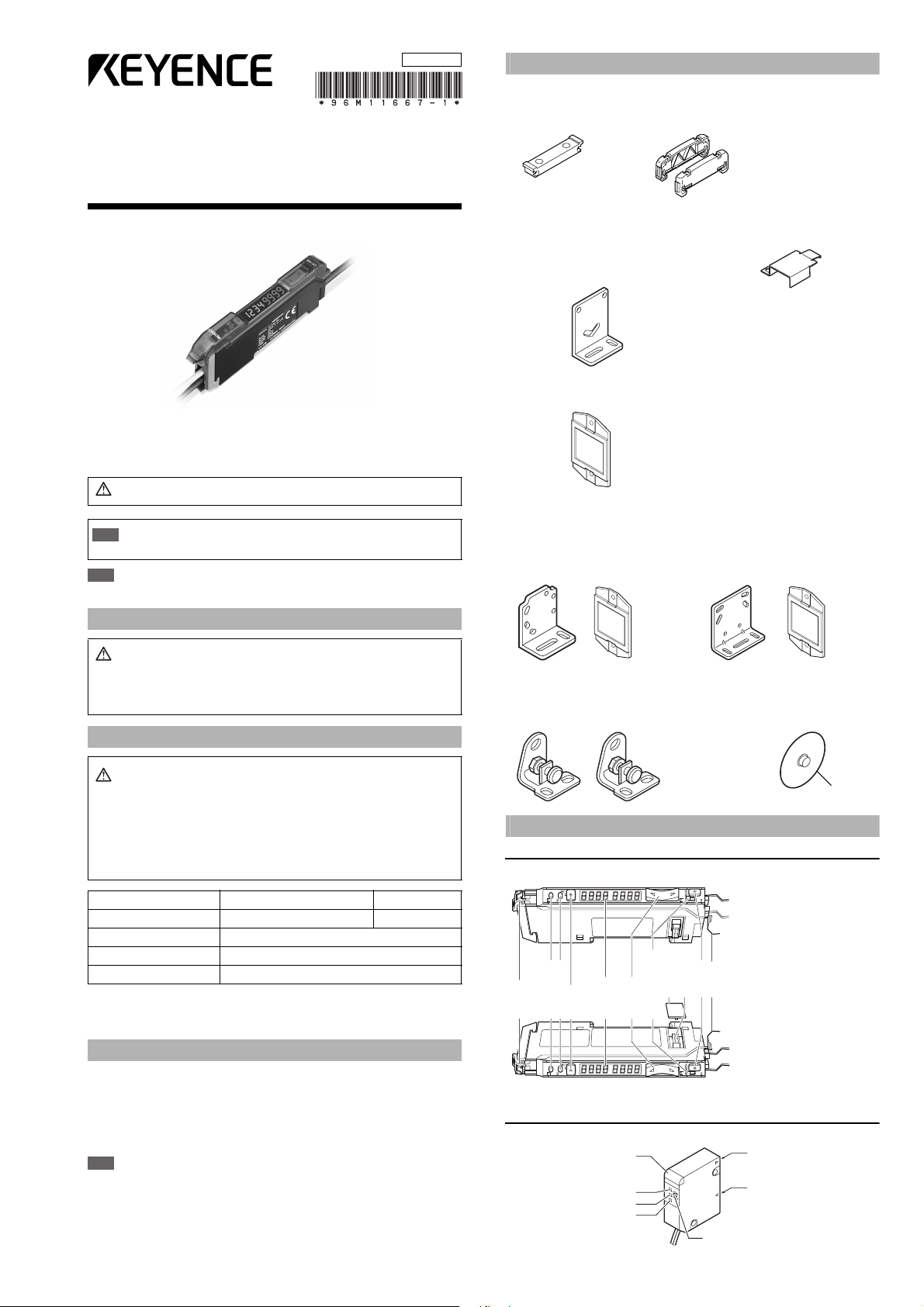
Accessories
■ Amplifier
Mounting bracket: 1 End unit: 2 Instruction Manual: 1
Supplied with LV-11SB (P) Supplied with LV-12SB (P)
■
LV-S31 dedicated accessories
Mounting bracket: 1
Plate nut: 1
M3 x 15 screw: 2
Adjustment screwdriver: 1
■
LV-S62 dedicated accessories
Reflector (R-6L): 1
■
LV-S41/S41L dedicated accessories
Mounting bracket: 1
Warning
Important
Failure to follow instructions may lead to injury.
Indicates warnings and restrictions that must be followed during
operations.
Note
Provides additional information on proper operations that can be easily mistaken.
Safety Information for LV-S series
•
Warning
This product is just intended to detect the object(s). Do not use this
product for the purpose to protect a human body or a part of human
body.
•
This product is not intended for use as explosion-proof product. Do not
use this product in hazardous location and/or potentially explosive
atmosphere.
Safety precautions on laser products
Warning
FDA(CDRH) Part 1040.10* Class 1 Laser Product
* The classification is implemented based on IEC60825-1 following the
requirements of Laser Notice No.50 of FDA (CDRH).
• U se of controls or adjustments or performance of procedures
other than those specified herein may result in hazardous radiation exposure.
• This product employs a semiconductor laser for its light source.
• Follow the instructions mentioned in this manual. Otherwise, injury
to the human body (eyes and skin) may result.
Precautions on class 1 laser products
•
Do not disassemble this product. Laser emission from this product
is not automatically stopped when it is disassembled.
•
Do not stare into the beam.
Sensor head LV-S31/S41/S41L/S61/S71/S72 LV-S62/S63
Wavelength 655 nm 660 nm
Output 290 μW
IEC 60825-1 Class 1 Laser Product
■
LV-S61 dedicated accessories
Mounting bracket: 1
Plate nut: 1
M2 x 12 screw: 2
Reflector (R-6): 1
■
L-shaped mounting bracket: 1
M4 nut: 3
M4 x 30 screw: 3
Reflector (R-9): 1
■ LV-S71/S72 dedicated accessories
Mounting bracket: 2 Nut: 4
Facing ring: 2
Washer: 2
Identifying Part Names
Amplifier
■ LV-12SB (P) (Expansion unit)
Connector protection
cover
Extension connector
MODE button
Output indicator lamp
(for control output 1)
Hold lock bar
Output indicator lamp
(for control output 2)
SET button
Digital monitor
Manual button
Channel selection switch
(display settings)
LV-S63 dedicated accessories
Beam axis adjustment cap: 1
ø30
Dust cover
Safety Measures for the Laser
■ Laser emission stop input
The laser emission can be stopped by selecting the “Laser emission stop” signal
(20 ms or more) from the input functions and inputting it externally.
The emission stops while the signal is being input. The laser beam is emitted in 20 ms
after the signal input is canceled. The control output functions according to the
received light intensity even while laser emission stop is input.
Note
When the power is turned on, even when the laser emission stop signal is
input, the laser is emitted for about 60 ms for self-diagnostic purpose.
E LV-S-IM
■ LV-11SB (P) (Main unit)
Sensor head
■ LV- S3 1
Operation indicator (red)
FAR indicator (red)
J
U
T
S
i
i
n
d
c
a
NEAR indicator (red)
1
Transmitting section
F
F
J
N
o
t
g
(
r
r
e
e
n
N
)
Receiving section
Adjustment trimmer
Page 2
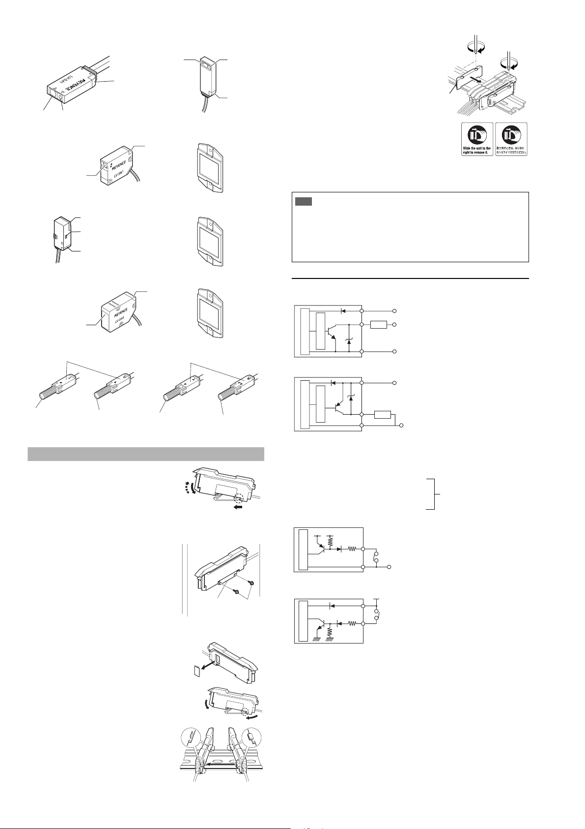
■ LV- S 41
r
Receiving
Transmitting section
section
■ LV- S 61
Transmitting section,
Receiving section
■ LV- S 62
■ LV- S 63
Transmitting section,
Receiving section
Operation
indicator
(red)
Transmitting section,
Receiving section
Spot selection switch
Operation indicator
(red)
■ LV- S4 1 L
Receiving
section
Operation
indicator (red)
Operation
indicator (red)
Transmitting
section
Operation
indicator
(red)
Reflector (accessory)
Reflector (accessory)
Reflector (accessory)
4 Install the end units on both ends of
the amplifier unit.
Fasten the screws on the top of the
end units (at two positions on both
end units) with the Philips screwdriver.
Two end units are
supplied with an
expansion unit.
OP-26751
* The stickers on the right are provided. Attach
the sticker on the place near the amplifier unit.
■ Removing the amplifier unit
1 Remove the end units.
2 Slide the expansion unit and remove it one by one.
•
Important
Input/Output Circuit Schematic
■ Output circuit
LV-11SB/12SB (NPN output type)
When installing additional expansion unit, be sure to use the DIN rail and the end units.
• Turn off the power when installing or removing the unit.
• Do not remove the protective cover of the extension connector on the
amplifier expansion unit that is added at the end.
•
Do not remove the amplifier unit with all added units attached, from the DIN rail.
•
Verify the operation ambient temperature after addi tional installati on. (“Specifications” page 11)
•
Do not use full calibration functions or stability output when the expansion unit of
the LV-S Series is connected to a device with full calibration functions (such as
FST or PS-T) via external input. Doing so may lead to product malfunctions.
Brown *
Black/white (control output 1/2)
Load
DC12-24V
DC5-40V
■ LV-S71
Operation indicator (red)
Tra ns mi t te r
Transmitting section
Receiver
Receiving section
■ LV- S7 2
Operation indicator (red)
Tra ns m it te r
Transmitting section
Receive
Receiving section
The operation indicator works in conjunction with the Output selected at the
channel selection switch. (It does with Output 1 in area detection mode.)
Mounting the Amplifier Unit
■ Mounting on a DIN rail
.
(3)
(2)
Mounting bracket
(OP-25431)
(1)
M3 screw
1)
Align the claw at the bottom of the main body with the
DIN rail. While pushing the main body in the direction
of the arrow 1, slant it in the direction of the arrow 2
2)
To dismount the sensor, raise the main body
in the direction of the arrow 3 while pushing
the main body in the direction of the arrow 1.
■
Installation using the mounting bracket (accessory) (LV-11SB/11SBP only)
Mount the amplifier unit using the supplied
mounting bracket as shown in the figure.
■ Connecting several amplifier units
Up to 16 expansion units LV-12SB can be installed to the main unit LV-11SB.
1 Remove the protection cover on the side of the
main unit.
Overcurrent protection circuit
Sensor main circuit
Blue *
0V
* LV-11SB only
LV-11SBP/12SBP (PNP output type)
Overcurrent protection circuit
Sensor main circuit
Brown *
Black/white (control output 1/2)
Blue *
DC12-24V
Load
0V
* LV-11SBP only
The power of the expansion unit LV-12SB (P) is supplied by the Extension connector on the side of the main unit LV-11SB (P). The power wires (brown and blue) of
the main unit and those of the expansion unit are unified inside by the connector.
■ Input circuit
• Not to be used
• Light emission stop input
• External calibration input
• Setting value bank selection input
• Received light intensity shift input
LV-11SB/12SB (NPN output type)
DC3.3V
Pink (input)
PLC etc.
(Short-circuit current 1 mA max.)
Sensor main circuit
Blue *
0V
* LV-11SB only
LV-11SBP/12SBP (PNP output type)
DC12-24V
Brown *
PLC etc.
Pink (input)
Sensor main circuit
* LV-11SBP only
(Short-circuit
current 2 mA max.)
Select either one.
(switched by the amplifier
function selection)
2 Install the amplifier one by one on the DIN rail.
3 Engage the two claws of the expansion
unit with the recesses on the main unit
side until you hear a click sound.
(2)
(1)
2
E LV-S-IM
Page 3
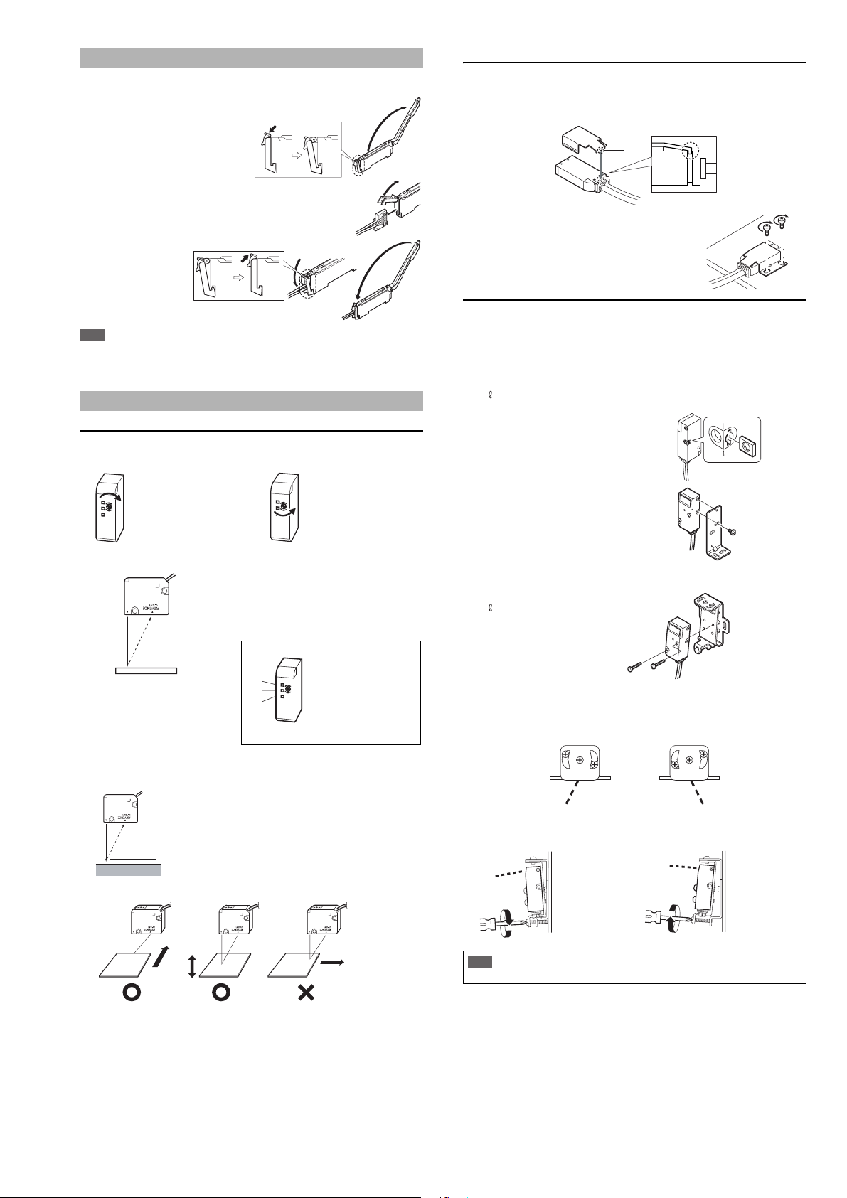
Connecting the Sensor Head and the Amplifier Unit
■ How to connect the amplifier unit and the connector
1 Open the dust cover, and tilt the
hold-lock lever.
LV-S41/S41L
Be sure to use the supplied mounting bracket.
1 Press the mounting bracket on the sensor head.
Be sure to hook the A portion of the mounting bracket on the B portion of
the sensor head.
A
2 Raise the hook, and insert the
connector to the very end.
3
Lower the hook and
hook the part shown
in the figure, and
then raise the holdlock lever.
Note
When shortening the sensor head cable, follow the instructions given in the
“Sensor Head Connector Assembly Procedures” included with the sensor
head.
Mounting and Adjusting the Sensor Head
LV- S3 1
■ Adjusting the trimmer (detection position)
The detection range can be selected as desired by adjusting the trimmer.
When detecting the target
from a long distance, turn the
trimmer clockwise to adjust.
F
F
J
N
N
■ Adjusting the center of detection
1
When detecting the target
from a short distance, turn the
trimmer counterclockwise to
F
F
adjust.
J
N
N
Place the workpiece at the position you
want to set as the center of detection.
2 Turn the trimmer until JUST
indicator (2) illuminates in green.
When (1) illuminates, turn the
trimmer clockwise until (2)
(1)
(2)
(3)
Finer adjustment is possible by looking at the display on the amplifier (page 9).
■ Detecting a height difference
A stable detection is made possible by
adjusting the trimmer so that the middle
point of the height comes to the center of
detection.
Middle point
illuminates.
F
F
When (2) illuminates, the
J
N
N
adjustment is complete.
When (3) illuminates, turn the
trimmer counterclockwise
until (2) illuminates.
B
2 Install the sensor head on the flat surface with the
M3 screws as shown in the following figure.
(The M3 screw is not an accessory.)
LV-S62
Mount the sensor head using either L-shaped mounting bracket (OP-84350),
rear mounting bracket (OP-84349), side mounting bracket (OP-84351) sold
separately.
■ L-shaped mounting bracket (sold separately: OP-84350)
Mounting bracket 1
Plate nut 1
M3 x 7.3 screw 1
1 Insert the plate nut to the head.
2 Insert the protrusion on the amplifier for
securing the bracket into the hole at the
upper part of the bracket.
Limit the tightening torque
up to 0.5Nm
■ Rear mounting bracket (sold separately: OP-84349)
Mounting bracket 1
M3 x 18 screw 2
Limit the tightening
torque up to 0.5Nm
• Adjusting the beam axis
(1) The beam axis angle can be adjusted horizontally by swinging the
bracket to the left and right with screws (a), (b) and (c) loosened. In order
to tighten the screws, be sure to tighten screw (b) first.
(a)
(c)
(b)
(a)
(2) The angle of the beam axis can be changed downward if the screw indi-
cated by the arrow is tightened, and upward if loosened.
When you want to lower the beam axis. When you want to raise the beam axis.
(c)
(b)
■ Movement directions of the workpiece
Movement
direction
Detecting
object
Movement
direction
Detecting
object
Detecting
object
E LV-S-IM
Movement
direction
3
Be sure to adjust the beam axis in the order of (1) and (2).
Important
If the order is reversed, the screws in (1) may be damaged.
Page 4
■ Side mounting bracket (sold separately: OP-84351)
Mounting bracket 1
M3 x 18 screw 2
Note
When mounting the sensor head in the opposite direction as described previously, set the spot toggle switch before mounting.
• Adjusting the beam axis
The angle of the beam axis can be changed upward if the screw indicated by
the arrow is tightened, and downward if loosened.
When you want to raise the beam axis. When you want to lower the beam axis.
Spot toggle
switch
Limit the tightening
torque up to 0.5Nm
LV-S71/S72
Mount the sensor head such
that the letter “T” (on the
transmitter) or “R” (on the
receiver) faces upward. The
side where the operation indicator illuminates should face
upward.
• Adjusting the beam axis
The angle of the beam axis can be changed downward if the screw indicated
by the arrow is tightened, and upward if loosened.
When you want to lower the beam axis When you want to raise the beam axis
Adjust the spot to be emitted at the
center on the receiver.
The adjustment is facilitated by
attaching the beam-axis adjustment
cap supplied with the sensor head to
the tip of the receiver
. Once the
adjustment is complete, remove the
beam-axis adjustment cap.
Fixing nut
Beam axis
adjusting screw
Beam axis
adjustment cap
Limit the tightening
torque up to 1.2 Nm.
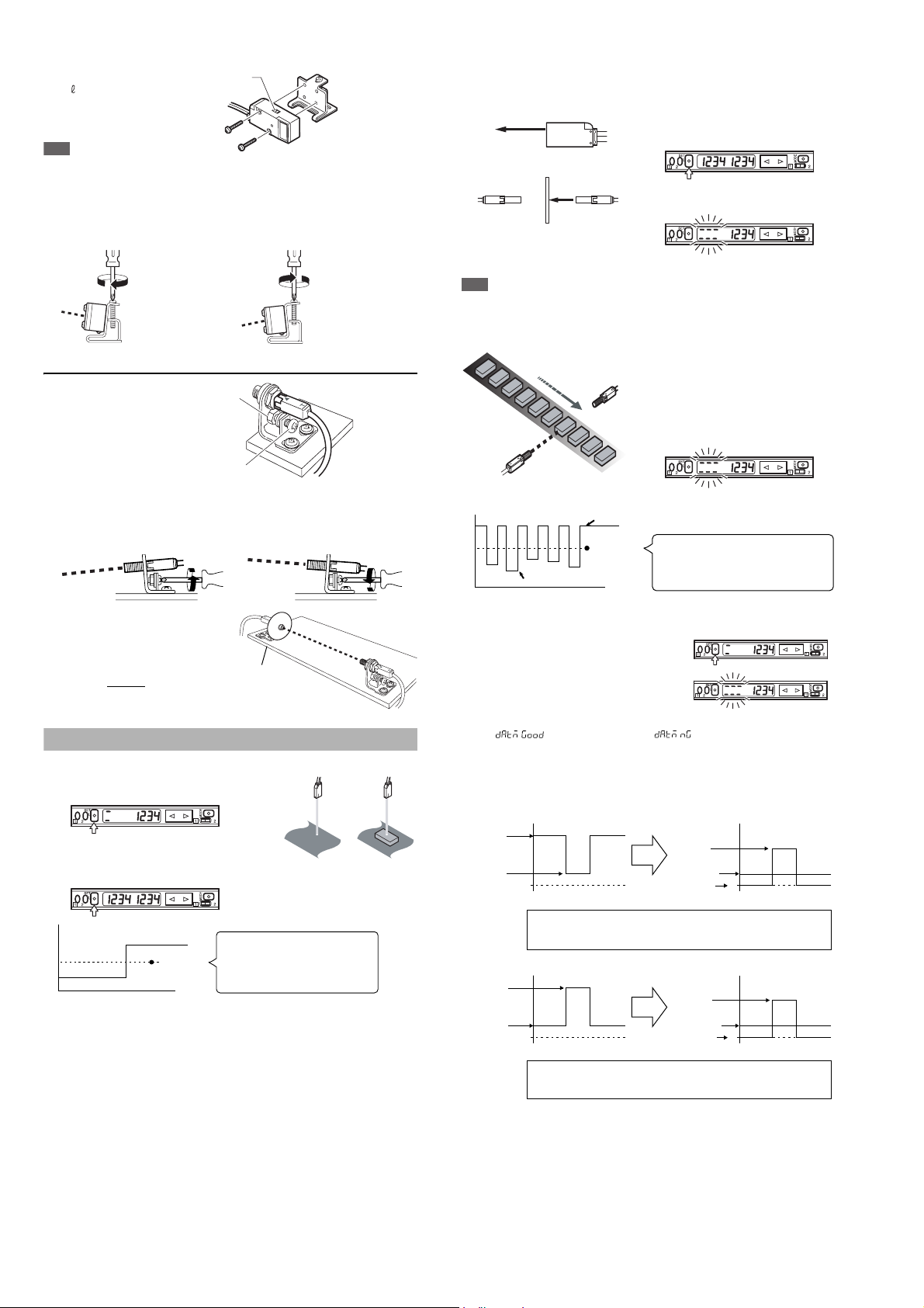
Setting Sensitivity
■ 2-point calibration
1 Press the SET button once without a
workpiece being placed.
12
2 Place a workpiece at the designated
position, and quickly press the SET
button once again.
2
1
Received light intensity
*
If the sensitivity difference does not have enough room, “
the calibration is complete. The setting value is changed at this time, too.
Setting value
The value set at the intermediate point
between the received light intensity
measured when the SET button is pressed
for the first time and that measured when it
is pressed for the second time.
Time
++++
” flashes after
■ Maximum sensitivity setting
Set the sensitivity without a workpiece in the case of the reflective type, and with
a workpiece in the case of the transmission type.
Reflective type
1 Press the SET button for three
seconds in the state as shown in
With no workpiece
Transmission type
the figure on the left.
The indication flashes when the setting
is complete.
With workpiece
2 Release the SET button.
Note
In the transmission type, if the value for the maximum sensitivity setting is the same as
DSC, the device will not operate correctly, so do not use the same value.
■ Full-auto calibration (not available for the LV-S31)
1
Let the workpiece pass while the SET
button is being pressed for three
seconds. (The sensitivity is set
according to the received light intensity
while the SET button is pressed.)
2
The indication flashes when the
setting is complete.
3 Release the SET button.
MAX
The value is set at the intermediate point
between the MAX value and the MIN value
of the received light intensity measured
while the SET button is pressed.
Received light intensity
MIN
Setting value
Time
Perform 2-point calibration if the setting cannot be configured as desired.
■ Zero datum calibration (not available for the LV-S31)
1 Press the SET button quickly without a
workpiece being placed.
2 Press the SET button for at least three
seconds. When the indication flashes,
release the button.
3 The calibration is complete when
" " is displayed. When " " is displayed, switch the
channel toggle switch to "2" and check the contents of the alarm.
*The alarm contents are only displayed when "Auto" is selected for "ALrt",
the operation of control output 2 in "4. Detection mode selection". (For
information about the display, see "Toggling the display" on page 9.)
Transmission/retro-reflective types
Received light
intensity without
workpiece
Received light
intensity with
workpiece
(Blocked light)
0 0
Reflective type
Received light
intensity with
workpiece
(Entered light)
Received light
intensity without
workpiece
0 0
In the transmission or retro-reflective type, when zero datum calibration is performed
without a workpiece, the received light intensity without a workpiece is used as zero and
the value indicates the amount of blocked light. The setting value is set automatically.
In the reflective type, when zero datum calibration is performed without a
workpiece, the received light intensity without a workpiece is used as zero and the
value indicates the amount of entered light. The setting value is set automatically.
Blocked light
Setting value
Received light
intensity without
workpiece
Entered light
Setting value
Received light
intensity without
workpiece
4
E LV-S-IM
Page 5

Note
• The zero datum calibration cannot be used when bank selection (bAnk) is
set for the control input function.
• The zero datum calibration can only be used with Output 1.
• When zero datum calibration is performed on models other than LV-S41/
S41L, the DSC function is turned on.
• When zero datum calibration is performed on LV-S41/S41L, the DSC function is turned off.
• After zero datum calibration is performed, the minus sign will not be displayed. In situations when the minus sign is supposed to be displayed, the
display stay as zero.
■ Positioning calibration (not available for the LV-S31)
1 Press the SET button quickly
without a workpiece being placed.
2
Place a workpiece on the position
where you want to perform positioning.
Setting value
Received light intensity
The sensitivity is set at the point where the value
becomes ON exactly when a workpiece comes
to the point where you want to position it.
Note
• Output 2 for Bank A and Outputs 1 or 2 for Bank B can be used.
• When the control input function is set to bank select (bAnk), Output 1 on
Bank A can be used.
3 Press the SET button for at least
three seconds. When the indication
flashes, release the button.
Time
■ % calibration (not available for the LV-S31)
This is a calibration method that can set the setting value by percentage with
reference to the received light intensity at the time of sensitivity setting. For
example, if the target value is set to –10P, the setting value is determined 10%
lower than the received light intensity when the SET button is pressed.
By regularly performing external calibration from the device such as a PLC,
even a little sensitivity difference can be steadily detected.
Note
The % calibration function cannot be used when the DSC function is turned
on or the zero datum calibration is being used.
1 When selecting the sensitivity
setting method (page 7, No. 5),
select the % calibration, and set
the target value of calibration.
(The value can be set by 1%.)
2 Taking the desired light intensity as
a reference (normally without a
workpiece), press the SET button.
* While the % calibration is in use, other calibrations (sensitivity setting) can-
not be used.
* The setting value is calculated based on the intermediate value between
MAX. and MIN. of the received light intensity while the SET button is being
pressed. The conditions in acquiring the sampling value can be changed
using the procedure to set the special modes.
■ Edge detection (not available for the LV-S31)
Detects the change in the received light intensity during a given period of time.
In the detection mode (page 7, No. 4), select the following edge detection
mode and the detection time.
Rising detection Detects the increase (rising edge) of
Falling detection Detects the decrease (falling edge) of
Rising/falling
(both-edge) detection
Sensitivity setting
The sensitivity is set to maximum when the SET button is pressed once.
(If the SET button is pressed and held for a while, changes in the light intensity during that period are ignored.)
Output status
Setting Operation
L-ON Always OFF. Turns ON only when the light intensity changes.
D-ON Always ON. Turns OFF only when the light intensity changes.
the received light intensity
the received light intensity
Detects both the rising and falling
edges of the received light intensity.
■ External calibration
1 Select the external calibration with the menu switch.
2 Short-circuiting the pink wire 20 ms or more as follows for each model is
equivalent to pressing the SET button.
LV-11SB/12SB LV-11SBP/12SBP
* LV-11SB/11SBP only
* The maximum number of times of writing is one million.
* Input is not accepted while setting any mode (page 7).
Brown*
Blue*
Pink
+V
0 V
Brown*
Pink
Blue*
+V
0 V
Fine-adjusting Sensitivity
The setting value can be directly changed by pressing the manual button.
When “five-digit display” is set (page 7, No.11) for the number of digits to be displayed for the received light intensity
1
Press the manual button quickly once, and check that the setting value flashes.
2 While the setting value is flashing, change the setting value with the
Manual button.
Note
When DSC and zero datum are activated, perform fine-adjustment without a
workpiece.
Area Detection Mode
This mode is suited to detecting the received light intensity only of a certain range.
To set this mode, select the area
detection mode among the
detection modes. (page 7, No. 4,
or page 8 No. 5)
The display of the setting values
of the upper and lower limits can
be switched with the channel
selection switch.
Keep the range of setting value 1 > setting value 2.
Nothing is detected when setting value 1 ≤ setting value 2.
Output 2 cannot be used while the area detection mode is in use.
Setting value 1
(Upper limit)
Setting value 2
(Lower limit)
Received light intensity
1: Setting value upper limit
2: Setting value lower limit
■ Sensitivity setting method 1 (Normal sensitivity)
OFF
ON
OFF
1 Place a workpiece on the upper
limit of the received light intensity
that you want the sensor to detect,
and press the SET button once.
1: Upper limit
2
2: Lower limit
If the sensitivity difference does not have enough room, “+++” flashes after
the calibration is finished. The setting value is changed at this time, too.
Place a workpiece on the lower limit
of the received light intensity that
you want the sensor to detect, and
press the SET button once again.
■ Sensitivity setting method 2 (when % calibration is selected)
1 Place a workpiece on the
designated position, and press the
SET button once.
Specify the setting values to the
upper and lower limits of the time
when you press the SET button.
Example: When the setting value of the % calibration is set to 10P
The value that is the received light intensity when the SET button is pressed
plus 10% is set for the setting value 1, and minus 10% for the setting value 2.
■ Bank function
Normally, up to two setting values can be set, but by using the bank function,
up to four setting values can be set.
E LV-S-IM
5
Page 6

Note
The zero datum calibration cannot be used when using the bank function.
1 When selecting the control input function (page 7, No.8, or page 8, No. 7),
select the bank selection.
2 Normal bank A becomes bank B when the external input wire (pink wire)
is short-circuited.
LV-11SB/12SB LV-11SBP/12SBP
Brown*
Blue*
Pink
+V
0 V
* LV-11SB/11SBP only
Set or change the bank B while the input signal is input.
Setting the Display Scaling (not available for the LV-S31)
This is the function to adjust the received light intensity during operation to the
“scaling target value”.
Note
This function cannot be used when zero datum calibration is being used.
1
When setting a display scaling (page 7, No. 6), select to use the display
scaling, and set the target value. (The explanation here deals with the case
where the target value is set to 2000.)
2
During the normal display, press the SET button while pressing the MODE button.
The display changes as follows, and the target value (which is 2000) to be
set as a scale is displayed.
Brown*
Pink
Blue*
+V
0 V
•
When connected to LV-S41/S41L, the DSC function turns off when the zero datum
calibration is performed and operates while turned on when there is entered light.
■ Alarm output level (ALrt) setting
Specify the operation for control output 2 when the DSC function is set to ON.
Mode Operation
Auto Control output 2 acts as an alarm output.
uSEr Control output 2 performs a usual operation.
■ Alarm output level (rtio) setting
Specify the level at which to output an alarm when the received light intensity
changes as moderately as the control output stays off (specifying the moderate fluctuation alarm level).
DSC is not performed during a period when the received light intensity falls
below the alarm level.
Specified range: 0 to 100%
100%: The moderate fluctuation alarm is not output.
50%: An alarm is output when the received light intensity changes from the
background state up to half the setting value.
0%: An alarm is output when the received light intensity gets any closer to
the setting value from the background state.
Note
Normally use the setting at 50%. Smaller values can affect the response and
prevent the alarm from becoming cleared.
Timing chart
Ex: When using a transmission or retro-reflective type
rtio
100%
Output 1 (Control output)
Output 2 (Alarm output)
Received light intensity
Received light intensity
Alarm state
Workpiece detection
Alarm level
Setting value
(no alarm)
The display scaling is performed.
↓
The reference light intensity can be set in the following range in reference with
the currently received light intensity:
Power mode Minimum value Maximum value
HSP Approx. 1/20 times Approx. 16 times
FINE Approx. 1/40 times Approx. 8 times
TURBO Approx. 1/80 times Approx. 4 times
SUPER Approx. 1/160 times Approx. 2 times
ULTRA Approx. 1/320 times Approx. 1 time
The error is indicated
when the value is out of
the range.
Special function
After an external calibration, the scaling can be externally performed by
inputting the signal again in three seconds.
• In the case of the % calibration (example)
Input ON
Input OFF
Input ON
Input OFF
%calibration Display scaling
Within 3
seconds
%calibration %calibration
3 seconds
or more
* Input is not accepted while setting any mode. (page 7)
DSC (Dynamic Stability Control)
DSC automatically corrects the setting value according to the changes in the
received light intensity when there is no workpiece (output OFF).
This function is effective when the light intensity difference is small when
judging whether or not there is a workpiece. At Detection mode selection
(page 7, No.4), select " ".*
How to set the sensitivity is the same as in the normal mode.
* The value is stored in memory even after the power is turned off.
Note
•
When connected to a sensor head other than LV-S31/S41/S41L, the DSC function turns on automatically when the zero datum calibration is performed and
operates while turned on when there is blocked light. When other calibrations are
performed in this state, the DSC function is turned off.
Shift Function
Forcibly synchronizes the received light intensity with the preset value (shift
target value). (Adds and subtracts the received light intensity.)
Regular synchronization inputs from a PLC or other device stabilizes the
detection of the target that has a little light intensity difference.
Note
The shift function cannot be used when the DSC function is turned on or the
zero datum calibration is being used.
1 When setting a shift function (page 7, No. 7, or page 8, No. 6), select to
activate the shift function, and set the shift target value.
LV-11SB/12SB LV-11SBP/12SBP
Brown*
Blue*
Pink
+V
0 V
* LV-11SB/11SBP only
Whether or not to save the current display status changed by an external input
*
can be selected in the special mode (See “How to set the special mode” on
page 9). The default is to “Save”.
It is recommended that you set “Do not save” when the external input is frequently performed. The maximum number of times of writing is one million.
Hold Function
This function holds the peak value and the bottom value of the received light
intensity during operation.
At Hold mode selection (page 7, No.9), select the hold mode.
Hold mode Operation
Updates the peak and bottom values every time the current light
intensity exceeds or drops below the specified value.
Displays the maximum and minimum peak values since the
power is turned on (total number).
Displays the maximum and minimum bottom values since the
power is turned on (total number).
Displays the minimum peak value and the maximum bottom
value since the power is turned on (total number).
Displays the maximum peak value and the minimum bottom
value since the power is turned on (total number).
Brown*
Pink
Blue*
+V
0 V
6
E LV-S-IM
Page 7

How to Set up Each Mode (Models other than LV-S31)
The settings of Output 1 and 2 can be divided into common settings and individual settings depending on the modes. Change the mode by using the
channel selection switch. To exit the mode setting while it is not completely
finished, press the MODE button for over 2 seconds. Refer to page 8 when
using the LV-S31.
MODE
Press for two seconds
Selecting output
1
Press the or button to select.
•
•
2
Press the or button to select.
• HIGH SPEED:80
• FINE:250s
• TURBO:500s
• SUPER:2 ms
• ULTRA:4 ms
* Cannot be selected when LV-S62/S63 is being used.
Output 1/2 indiv idual setting
Turns ON while the light enters.
Turns ON while the light is shielded.
Selecting the power mode (response time)
When the power mode is changed, redo the calibration.
MODE
When Timer
OFF
is selected
a
When Output 1 is set
and zero datum
calibration is selected
When Output 2
When a mode
Normal or
Area detection
is selected.
MODE MODE
When a mode
DSC is
selected.
is set.
When zero
datum calibration
is selected for
Output 1
B
When a mode DSC is
selected for Output 1
and a mode Normal is
selected for Output 2
C
Output 1/2 common
µ
s
Selecting the Timer mode
3
Press the or button to select.
• Timer OFF
• OFF delay
When other
setting than
Timer OFF
is selected
OR
• ON delay
• One-shot
•
•
Timer setting
Press the or button to select.
MODE
When selecting a timer mode,
If other setting than *1 is selected → a
If *1 is selected → b
b
MODE
Can be set between 0.1 and 5000 ms.
When *1 is selected, the ON delay
timer is activated.
Timer setting 2
Sets an OFF delay (one-shot) time.
Press the or button to select.
Can be set between 0.1 and
5000 ms.
A
(If the sensor head is “LV-S41/S41L”
Selecting the detection mode
4
Press the or button to select.
When a mode other
than Normal, DSC,
or Area detection
is selected
• Normal (light intensity) mode
• Area detection mode
• Area detection mode
•
•
•
of the received light intensity
The % calibration function cannot b e used when the
DSC function is turned on or the zero datum
calibration is being used.
The shift function cannot be used w hen the DSC
function is tur ned on or the zero datum calibration is
being used.
Selecting the derivation time
Press the or button to select.
The time can be selected from 0.25/0.5/1/2.5/
B
5/10/25/50/100 ms. (The available times vary
A
depending on the power mode.)
Selecting the detection operation
Press the or button to select.
•
[light intensity with workpiece >
light intensity without workpiece]
(The output is on when the light
enters)
•
[light intensity with workpiece <
light intensity without workpiece]
(The output is on when the light
is blocked.)
Output 1/2 indiv idual setting*
Detects the rising edge of the received light intensity.
Detects the falling edge of the received light intensity.
Detects both the rising and falling edges
or more
MODE
MODE
When Output 2 is
set, Alarm output is
selected, and
"Auto" is selected
End of the basic
menu display
Output 1/2 indiv idual setting
ON delay, OFF delay *1
ON delay, one-shot *1
B
L-on Mainly for reflective type
d-on Mainly for thrubeam type
Selecting the correction speed
Press the or button to select.
The correction is made faster as
the number b ecomes larger (1 to 3).
(Select 1 for normal cases.)
Mode LEv1 LEv2 LEv3
Correction 104.86s 1.64s 25.6ms
speed
Selecting the operation for control output 2
Press the or button to select.
•
Uses normal operations for
control output 2.
•
Uses alarm output for control
output 2.
Setting the range for alarm output level
Press the or button to select.
Set in the range between 0 and 100P.
* Normally use the setting at 50% .
B
Selecting the sensitivity selecting method
5
Press the or button to select.
• Normal sensitivity setting
• % calibration
Setting the target value of the %
calibration
Press the or button to select.
From –99% to +99% can be set.
Setting the display scaling
6
Press the or button to select.
• Normal display
• Display scaling
Setting the display scaling target value
Press the or button to select.
It can be set by the unit of 100.
Output 1/2 common
Output 1/2 common
C
MODE
MODE
When OFF
is selected
When zero datum
calibration or % or
calibration is selected
When zero datum
calibration are selected
C
When %
calibration
is selected
When ON is
selected
DSC
MODE
MODE
MODE
B
Setting the shift function
7
MODE
When OFF
is selected
When ON is
selected
B
MODE
MODE
)
MODE
MODE
When DSC mode,
display scaling,
or zero datum
calibration are
MODE
selected
Press the or button to select.
• Do not use shift
• Use shift
Setting the shift target value
Press the or button to select.
It can be set by the unit of 1.
Selecting the control input function
8
Press the or button to select.
• Does not use the control input
• External calibration
• Bank selection
• Laser emission stop
Selecting the hold function
9
Press the or button to select.
•
Updates the peak/bottom value every time that the
current light intensity is less than or more than the set value
•
Displays the maximum and minimum peak values
since the power was turned on (total number)
•
Displays the maximum and minimum bottom values
since the power was turned on (total number)
•
Displays the minimum peak value and the maximum
bottom value since the power was turned on (total number).
•
Displays the maximum peak value and the minimum bottom
value since the power was turned on (total number).
Selecting the display mode
10
Press the or button to select.
• Normal screen display mode
• Full screen display mode
Selecting the number of digits of light intensity display
11
Press the or button to select.
•
Four-digit display (the setting value is also displayed)
• Five-digit display
Output 1/2 common
Output 1/2 common
Output 1/2 common
Output 1/2 common
Output 1/2 common
End program
* When Area detection mode is selected in "4.Selecting the detection mode", "----" is displayed in
the Output 2 setting and Output 2 cannot be selected.
If a mode other than the Normal/Dsct Area detection mode is selected for either Output 1 or 2, the
setting of item 5 or 6 or 7 cannot be selected for both Output 1 and 2.
E LV-S-IM
7
Page 8

How to Set up Each Mode (LV-S31)
The settings of Output 1 and 2 can be divided into common settings and individual settings depending on the modes. Change the mode by using the
channel selection switch. To exit the mode setting while it is not completely
finished, press the MODE button for over 2 seconds.
MODE
Press for two
1
Selecting output
Output 1/2 individual setting
Press the or button to select.
Turns on the output nearer to the sensor.
•
•
Turns on the output farther to the sensor.
2
Selecting the power mode
Press the or button to select.
• Normal mode
•
High-speed mode (response time 250 µs)
3
Selecting the response time
Press the or button to select.
Varies depending on the power mode.
SPEED Response time
1 500µs
2 2ms
3 8ms
4 32ms
When the power mode is HSP, the
response time is fixed to 250 µs.
Output 1/2 common
Output 1/2 common
seconds or more
MODE
MODE
When Std is selected
MODE
When
HSP is
selected
When OFF
is selected
MODE
MODE
MODE
6
Setting the shift function
When
ON is
selected
MODE
Press the or button to select.
• Do not use shift.
• Use shift.
7
Selecting the control input function
Press the or button to select.
• Does not use the control input
• External calibration
• Bank selection
• Laser emission stop
8
Setting the hysteresis mode
Press the or button to select.
•
•
Hysteresis: large
(End Program)
Output 1/2 common
Setting the shift target value
Press the or button to select.
It can be set by the unit of 1.
Output 1/2 common
Output 1/2 common
Hysteresis: small
When Timer
OFF
is selected
MODE
a
MODE
4
Press the or button to select.
• Timer OFF
When other
setting than
Timer OFF
is selected
b
• OFF delay
• ON delay
• One-shot
•
•
MODE
When selecting a timer mode,
If other setting than *1 is selected → a
If *1 is selected → b
OR
MODE
5
Press the or button to select.
• Normal detection mode
• Area detection mode
End of the basic
menu display
Selecting the timer mode
Selecting the detection mode
Output 1/2 individual setting
ON delay, OFF delay *1
ON delay, One-shot *1
Timer setting
Press the or button to select.
Can be set between 0.1 and 5000 ms.
When *1 is selected, the ON delay timer is
activated.
Timer setting 2
Sets an OFF delay (one-shot) time.
Press the or button to select.
Can be set between 0.1 and 5000 ms.
Output 1/2 individual setting
* Output 2 cannot be used when the Area detection mode is selected.
If a mode other than the Normal/Area detection mode is selected for either Output 1 or 2, the
setting of item 5 or 6 cannot be selected for both Output 1 and 2.
How to set up special modes
■ When using a model other than LV-S31
MODE SET
Press , , and for three seconds or more at the same time.
Selecting the Power saving function (Eco mode)
Press the or button to select.
MODE
MODE
MODE
MODE
• Normal use
• Eco-half
• Eco-all
Selecting the memory of value set by an
external input while using the shift function
Press the or button to select.
• Saves the value *1
•
Does not save the value (clears data at power-off)
*1 Data can be saved up to one million times.
Selecting the acquisition of the sampling
value* (received light intensity)
Press the or button to select.
Use the average value from sampling
•
• Use the peak value from sampling
• Use the bottom value from sampling
* Used during % calibration or display scaling.
Selecting the shift function input time
Press the or button to select.
• 5ms
• 20ms
The input time is fixed to 20 ms for all other functions.
Switching zero datum settings
Press the or button to select.
• Standard
• Hight-accuracy
* When Hi (High-accuracy) is selected, the width for the zero
datum setting value becomes smaller. During this state, be
especially aware of shocks and other causes of fluctuation.
(End Program)
8
E LV-S-IM
Page 9

■ When using the LV-S31
MODE SET
Press , , and for three seconds or more at the same time.
Selecting the Power saving function (Eco mode)
MODE
MODE
MODE
Press the or button to select.
• Normal use
• Eco-half
• Eco-all
Selecting the memory of value set by an
external input while using the shift function
Press the or button to select.
• Saves the value *1
•
Does not save the value (clears data at power-off)
*1 Data can be saved up to one million times.
Selecting the shift function input time
Press the or button to select.
• 5ms
• 20ms
The input time is fixed to 20 ms for all other
functions.
(End Program)
Toggling the Display
■ When using a model other than LV-S31
• When "duAl" is selected for the number of digits of light intensity display and "Std" is selected for display mode
When zero datum calibration is not selected
Setting value Current value Margin Current value
When zero datum calibration is selected
Press
Press
MODE
MODE
When zero datum calibration is selected
MODE
Press
Current value after
zero datum calibration
Current value before
zero datum calibration
Bar display*2Current value after
Current value after
zero datum calibration
MODE
Press
Margin*1Current value before
zero datum calibration
MODE
Press
Current value before
zero datum calibration
MODE
Press
zero datum calibration
Press
MODE
Output status Power mode
Peak value
margin
Peak value before
zero datum calibration
MODE
Press
Bottom value
3
margin*
MODE
Press
Bottom value before
zero datum calibration
Flashes
alternately
Flashes
alternately
*1 The received light intensity is displayed in percentage with reference to
the setting value.
*2 Its stability is indicated between 85 to 115 %. The number is varied by
the unit of 5 %.
*3 The peak- and bottom-hold values since the power-on are displayed.
The hold values can be reset by pressing the manual button.
• When "rE" is selected for the number of digits of light intensity display
MODE
Press
Flashes
alternately
Current value
Peak-hold value
Bottom-hold value
■ When using the LV-S31
Setting value Current value
When "Auto" is selected for the operation of control output 2 and
the channel setting is switched to "2"
after zero datum
calibration
When zero datum calibration is completed without errors
When zero datum calibration is completed with errors
(The display shown to the left appears after " " is
displayed during zero datum calibration)
(The display shown to the left appears after " " is
displayed during zero datum calibration)
Alarm contents*
Margin Current value
before zero datum
calibration
* The displayed number indicates the following type of alarm.
For more information about remedies to errors, see "Error indication" on page 10.
1: Over DSC correction limit
2: DSC small fluctuation detection
3: Invalid DSC EEPROM contents
4: Over fluctuation width during zero datum calibration
5: DSC speed limit alarm
• When "duAl" is selected for the number of digits of light intensity display and "FuLL" is selected for display mode
When zero datum calibration is selected
MODE
Press
Setting value Current value
1
Margin*
Bar display*
Press
Current value
Press
2
Current value
MODE
MODE
Press
Output status Power mode
Peak value
margin
MODE
Peak value Bottom value*
MODE
Press
Bottom value
margin*
MODE
Press
Flashes
alternately
3
Flashes
alternately
3
Setting value Current value
(1)
MODE
Press
Position display
(2)
(1)
Digital display (The position of the target from the center position
Press
Press
MODE
(3)
Peak value Bottom value
MODE
[5000] is displayed in number.)
Outside of the detection range
The workpiece is near the sensor with reference
to the digital display range.
With 5000 being the middle, the value
increases as the distance from the sensor increases.
The workpiece is far from the sensor with reference to
the digital display range.
Outside of the detection range
(2)
Position display (The position of the target with reference to the
center position is displayed.)
Outside of the detection range
The number of bars increases as the distance from
the sensor increases, taking the state of "A" as the
center.
When adjusting the center position with the trimmer
A
(3)
The peak/bottom hold value since the power is turned on is displayed.
on the sensor head, adjust it to the state of "A".
Outside of the detection range
Pressing the Manual button can reset the hold value.
Flashes
alternately
E LV-S-IM
9
Page 10

Interference Protection Function
The LV-S Series can prevent mutual interference by connecting amplifier units.
■ When using a model other than LV-S31
Power mode HSP (HIGH SPEED) FINE/TURBO
Number of units required to
prevent interference
Unavailable 2 units 4 units
■ When using the LV-S31
Power mode HSP (HIGH SPEED) STD
Number of units required to
prevent interference
2 units 4 units
SUPER/ULTRA
Caution on a lustrous workpiece (LVS31)
If the workpiece is lustrous, the trimmer adjustment may not succeed or
detection may be unstable. In such a case, install the sensor slightly tilted.
Keylock
You can lock the operation buttons to prevent the settings from being
changed by careless operation of the buttons.
Setting operations for sensitivity or modes are disabled during keylock, but
the display can be switched.
While pressing the
MODE button, press
the or button for
at least three seconds.
The indicator shows that keylock is activated.
• The same steps can be taken to deactivate keylock.
Power-save (Eco Mode)
The numerical display disappears, and the current consumption is reduced.
If a key operation is performed during the Eco mode, the display returns to
normal. If no more key operation is performed for 4 seconds, the display
returns to the Eco mode.
Cautions on Installing the Reflector (LV-S61/S62/S63)
Be sure to install the reflector so that it is vertical or horizontal against the sensor unit.
If the reflector is installed diagonally against the sensor unit, the received light
intensity will decrease significantly.
Error Indication
The following indications on the LCD display show the error events. Correct
the problem using the following countermeasures.
Error indication Cause Remedy
ErH
ErC
ErE
Sensor head is not
connected.
Head cable is broken.
Overcurrent flows through
the output wire.
Data write/read error • Per form initialization.
Data has been written in
the EEPROM more than
one million times and can
no longer be updated.
The following table shows the alarms when "Auto" is selected for the operation
of control output "2"and channel setting is switched to "2". Refer to the following table to remedy the alarms.
Display Alarm contents Remedy
Over DSC correction limit:
Received light intensity
during OFF exceeds the
DSC correction limit.
DSC small fluctuation
detection:
There are fluctuations
within the range for the
alarm output level (rtio).
Invalid DSC EEPROM
contents:
Failed to write data to
EEPROM.
Over fluctuation width during
zero datum calibration:
The fluctuations of
received light intensity
during calibration are too
large.
DSC speed limit alarm:
The received light intensity
fluctuated a large amount
in a short period of time.
• Check that the sensor head is
connected.
• Check that the head cable is
not broken.
• Check the connection of the
head cable to the connector.
• After checking these points,
turn on the power again.
• Check the load and reduce
the current to be within the
rated range.
• Check that the output wire
does not touch another wire or
a frame.
• If you need to write more data,
replace the amplifier unit.
Change the setup conditions or
replace the sensor, and secure
the correct received light
intensity during OFF.
Move the workpiece to the
correct position.
Restart the power or initialize.
Take anti-vibration measures in
order to suppress fluctuations
during calibration.
• Move the workpiece to the
correct position.
• Take anti-vibration measures
in order to suppress
fluctuations in the received
light intensity.
10
E LV-S-IM
Page 11

Specifications
■ Sensor head
Shearing machine
type
Model LV-S31 LV-S41 LV-S41L LV-S61 LV-S62 LV-S63 LV-S71 LV-S72
Light source
FDA (CDRH)
Part1040.10
IEC 60825-1 Class 1 Laser Product
Detecting range
Spot diameter Approx. ø2 mm
Indicator
Standard detecting
object
Operating ambient
temperature
Operating ambient light
Vibration resistance 10 to 55 Hz, 1.5 mm double amplitude in the X, Y, and Z directions, 2 hours respectively
Material
*1 When Spot 2 x 10 mm is selected (Values inside the parentheses ( ) indicate when Spot 2 x 2 mm is selected)
*2 When detecting a transparent glass object, install and set the LV-S63 so that the received light intensity without the glass object becomes 1000 or more.
Housing
material
Display
section
Lens
section
Cable PVC
Mounting
bracket
Reflector
(R-4, R-6L, R-9)
Weight Approx. 75 g Approx. 70 g Approx. 70 g Approx. 65 g Approx. 110 g Approx. 70 g
■ Amplifier
Shearing machine type Main unit Expansion unit
NPN output LV-11SB LV- 12 SB
1
Model
*
PNP output LV-11SBP LV- 12 SB P
Sensor head LV-S Series (LV-S31 / S41 / S41L / S61 / S62 /S63 / S71 / S72)
Response time *
Control output
Control input
Power voltage *
Rating
Vibration resistance 10 to 55 Hz, 1.5 mm double amplitude in the X, Y, and Z directions, 2 hours respectively
*1 The model with B (BP) at the end of the name has additional functions such as zero datum function.
*2 The response time during Edge detection mode is the detection mode set on Page 7. Also, when one side of the output is used for Edge detection mode while HSP mode
*3 When you connect eight or more amplifiers, limit the power voltage to 24 VDC ripple (P-P) 10 %.
*4 When several units are connected, the operating ambient temperature varies depending on the number of units to be connected. When connecting several units, be sure to
Current
consumption
Operating ambient
temperature
Material Housing material: Polycarbonate
Weight (including
cable)
The LV-S62/S63 operates normally only with an amplifier unit that has B (BP) at the end of the model name.
The LV-S31/S61 operates normally only with an amplifier unit that has A (AP) or B (BP) at the end of the model name.
is selected, the response time is 125 μs even when Normal detection or Area detection modes are selected. LV-S62/S63 does not handle HSP mode.
mount the units on the DIN rail (mounted on a metal plate), and keep the output current at 20 mA or less.
When 1 to 2 units are connected : -10°C to +50°C
When 3 to 10 units are connected : -10°C to +50°C
When 11 to 16 units are connected : -10°C to +45°C
2
4
*
Distance setting
type
Visible light semiconductor laser Wavelength 655 nm Output 290 μW
50 to 200 mm
(Adjustment
range)
Operation
indicator lamp
Red LED x 1
Beam axis
adjustment
indicator lamp
Red LED x 2,
Green LED x 1
100 mm blank
paper
0 to +50 °C
(No freezing)
Norbomenic
resin
Polyarylate
- - - Polycarbonate, Acrylic resin - -
3
Reflective type
ULTRA : 500 mm
SUPER : 400 mm
TURBO : 300 mm
FINE : 200 mm
HSP : 150 mm
Approx. ø1.2 mm Approx. ø1.2 mm Approx. ø2.5 mm
2 mm blank paper
Polycarbonate Polyarylate Polycarbonate
Norbornenic
resin
HSP : 80 μs
FINE : 250 μs
TURBO : 500 μs
SUPER : 2 ms
ULTRA : 4 ms
Light emission stop input/external calibration input/Setting value bank selection input/received light intensity shift input
Reflective, side
view type
ULTRA : 400 mm
SUPER : 320 mm
TURBO : 240 mm
FINE : 160 mm
HSP : 120 mm
Glass reinforced resin
Acrylic resin Acrylic resin
Only when using the LV-S31
When the detection mode is HSP: Response time 250 μs
When the detection mode is STD
Input time (other than shift input) 20 ms fixed, (shift input) 5 ms/20 ms selectable
Normal: 1.7 W max. (140 mA max. at 12 V, 70 mA max. at 24 V)
Eco-all/Eco-half: 1.55 W max (130 mA max. at 12 V, 65 mA max. at 24 V)
Straight beam,
retro-reflective type
Class 1 Laser Product
ULTRA : 2000 mm
SUPER : 1500 mm
TURBO :1000 mm
FINE : 750 mm
HSP : 500 mm
Operation indicator lamp
Red LED x 1
Opaque object
of
ø2.5 mm
-10 to +50 °C (No freezing)
Incandescent lamp : 10,000lx Sun light 20,000lx
SUS304
NPN (PNP) open collector x 2ch
40 VDC (30 V) max
100 mA max per output
12-24 VDC, Ripple (P-P): 10% max, Class2
-10 to +50 °C (No freezing)
Approx. 80 g
Area retro-reflective Transmission type
Visible light semiconductor laser
Wavelength 660 nm
Output 290 μW
ULTRA :
1
10m (5m)
*
SUPER : 8m (3.5m)
TURBO : 5m (2m)
FINE : 2.5m (0.7m)
Switch with two levels:
Approx. 2 x 10 mm /
Approx. 2 x 2
(within 500 mm
When spot 2 x 10
mm is selected:
2 x 10mm,
0.5-mm-thick
transparent glass
(no AR coated)
When spot 2 x 2 mm
is selected:
0.5-mm-thick opaque
1
*
1
*
1
*
distance)
2
*
2 x 2mm,
2
glass
*
Speed 1 2 3 4
Response time 500μs 2ms 8ms 32ms
ULTRA : 30m
SUPER : 25m
TURBO : 15m
FINE : 8m
Approx. 8 x 12 mm
(within 3.5 m
distance)
8 x 12 mm,
0.5-mm-thick
transparent
glass (no AR
2
coated)
*
Visible light semiconductor laser
Approx. ø1.2 mm
(one on each of the transmitter and
Opaque object of
ø1.5 mm
Transmitter lens:
Norbornenic resin
Receiver lens:
Polyarylate
Wavelength 655 nm
Output 290 μW
500 mm
Operation indicator lamp
Red LED x 1
receiver)
(detection distance 0
Metallic section: SUS304
Resin section: Polyarylate
Norbornenic resin
Approx. ø6 mm
(with 500 mm
distance)
Opaque object of
ø1.0 mm
to 100 mm)
Opaque object of
ø0.8 mm
(detection distance
100 to 250 mm)
Opaque object of
ø0.8 mm
(detection distance
250 to 500 mm)
Transmitter lens:
Receiver lens:
Glass
E LV-S-IM
11
Page 12

Default Mode Settings (Initialization)
Model
Control output L-on no
Operation mode - - - - Std (standard)
Power mode FinE - - - -
Response time - - - - 4
END/FULL END END
Timer mode toFF toFF
Detection mode Std (standard) Std (standard)
Sensitivity setting method Std (standard) - - - -
Display scaling oFF - - - -
Shift function oFF oFF
Control input function oFF oFF
Hold function Std (standard) - - - -
Hysteresis setting - - - - LEV2
Display mode Std (standard) - - - -
Displayed digits of received light intensity
Power saving function oFF oFF
Memory function YES (save) YES (save)
Sampling value Std (average) - - - -
Shift function input time 20 (ms) 20 (ms)
Zero datum Settig Std (standard) - - - -
Setting value 1/2 50 5000
■ Resetting to the factory default settings
LV-S41 (L)/S61/S62/S63/S71/S72
duAl (four digits) - - - -
LV- S31
1 While pressing the MODE button, press the left side of the Manual button
five times. “ ” is displayed.
2 Press the Manual button, and select “ “.
3 Press the MODE button or the SET button.
The sensor returns to the default state.
Tips on Correct Use
• To extend the amplifier unit cable, use the cable with the nominal crosssectional area no less than 0.3 mm
m. (Contact your nearest KEYENCE office when in the event of additional
installation.)
• Separate the wiring of the sensor cable from the power line or the high voltage line, since the use of these lines in the same pipe generates noise,
which may cause malfunction or product breakdown.
• If you use a commercially available switching regulator, be sure to ground
the frame GND terminal and the GND terminal.
• Do not use the LV-S Series at a location where external light directly falls on
the light-receiving surface.
• When setting the sensitivity, the detection distance may vary depending on
the individual characteristics.
• If you wire the unit incorrectly, the LV-S Series may become hot, or the sensitivity may change.
• Do not connect the sensor head connector to the amplifier unit more than
100 times.
• Displayed values may slightly change depending on the environment (temperature shift, dust, etc.).
2
, and with the length no more than 100
WARRANTIES AND DISCLAIMERS
(1) KEYENCE warrants the Products to be free of defects in materials and
workmanship for a period of one (1) year from the date of shipment. If any
models or samples were shown to Buyer, such models or samples were
used merely to illustrate the general type and quality of the Products and
not to represent that the Products would necessarily conform to said
models or samples. Any Products found to be defective must be shipped
to KEYENCE with all shipping costs paid by Buyer or offered to KEYENCE
for inspection and examination. Upon examination by KEYENCE,
KEYENCE, at its sole option, will refund the purchase price of, or repair or
replace at no charge any Products found to be defective. This warranty
does not apply to any defects resulting from any action of Buyer, including
but not limited to improper installation, improper interfacing, improper
repair, unauthorized modification, misapplication and mishandling, such
as exposure to excessive current, heat, coldness, moisture, vibration or
outdoors air. Components which wear are not warranted.
(2) KEYENCE is pleased to offer suggestions on the use of its various
Products. They are only suggestions, and it is Buyer's responsibility to
ascertain the fitness of the Products for Buyer’s intended use. KEYENCE
will not be responsible for any damages that may result from the use of the
Products.
(3) The Products and any samples ("Products/Samples") supplied to Buyer
are not to be used internally in humans, for human transportation, as
safety devices or fail-safe systems, unless their written specifications
state otherwise. Should any Products/Samples be used in such a manner
or misused in any way, KEYENCE assumes no responsibility, and
additionally Buyer will indemnify KEYENCE and hold KEYENCE harmless
from any liability or damage whatsoever arising out of any misuse of the
Products/Samples.
(4) OTHER THAN AS STATED HEREIN, THE PRODUCTS/SAMPLES ARE
PROVIDED WITH NO OTHER WARRANTIES WHATSOEVER. ALL
EXPRESS, IMPLIED, AND STATUTORY WARRANTIES, INCLUDING,
WITHOUT LIMITATION, THE WARRANTIES OF MERCHANTABILITY,
FITNESS FOR A PARTICULAR PURPOSE, AND NON-INFRINGEMENT
OF PROPRIETARY RIGHTS, ARE EXPRESSLY DISCLAIMED.
IN NO EVENT SHALL KEYENCE AND ITS A FFILIATED ENTITIES BE
LIABLE TO ANY PERSON OR ENTITY FOR ANY DIRECT, INDIRECT,
INCIDENTAL, PUNITIVE, SPECIAL OR CONSEQUENTIAL DAMAGES
(INCLUDING, WITHOUT LIMITATION, ANY DAMAGES RESULTING
FROM LOSS OF USE, BUSINESS INTERRUPTION, LOSS OF
INFORMATION, LOSS OR INACCURACY OF DATA, LOSS OF
PROFITS, LOSS OF SAVINGS, THE COST OF PROCUREMENT OF
SUBSTITUTED GOODS, SERVICES OR TECHNOLOGIES, OR FOR
ANY MATTER ARISING OUT OF OR IN CONNECTION WITH THE USE
OR INABILITY TO USE THE PRODUCTS, EVEN IF KEYENCE OR ONE
OF ITS AFFILIATED ENTITIES WAS ADVISED OF A POSSIBLE THIRD
PARTY’S CLAIM FOR DAMAGES OR ANY OTHER CLAIM AGAINST
BUYER. In some jurisdictions, some of the foregoing warranty disclaimers
or damage limitations may not apply.
BUYER'S TRANSFER OBLIGATIONS:
If the Products/Samples purchased by Buyer are to be resold or delivered
to a third party, Buyer must provide such third party with a copy of this
document, all specifications, manuals, catalogs, leaflets and written
information provided to Buyer pertaining to the Products/Samples.
E 1110-2
11666E 1041-1 96M11667
12
2011
E LV-S-IM
 Loading...