

Page 1
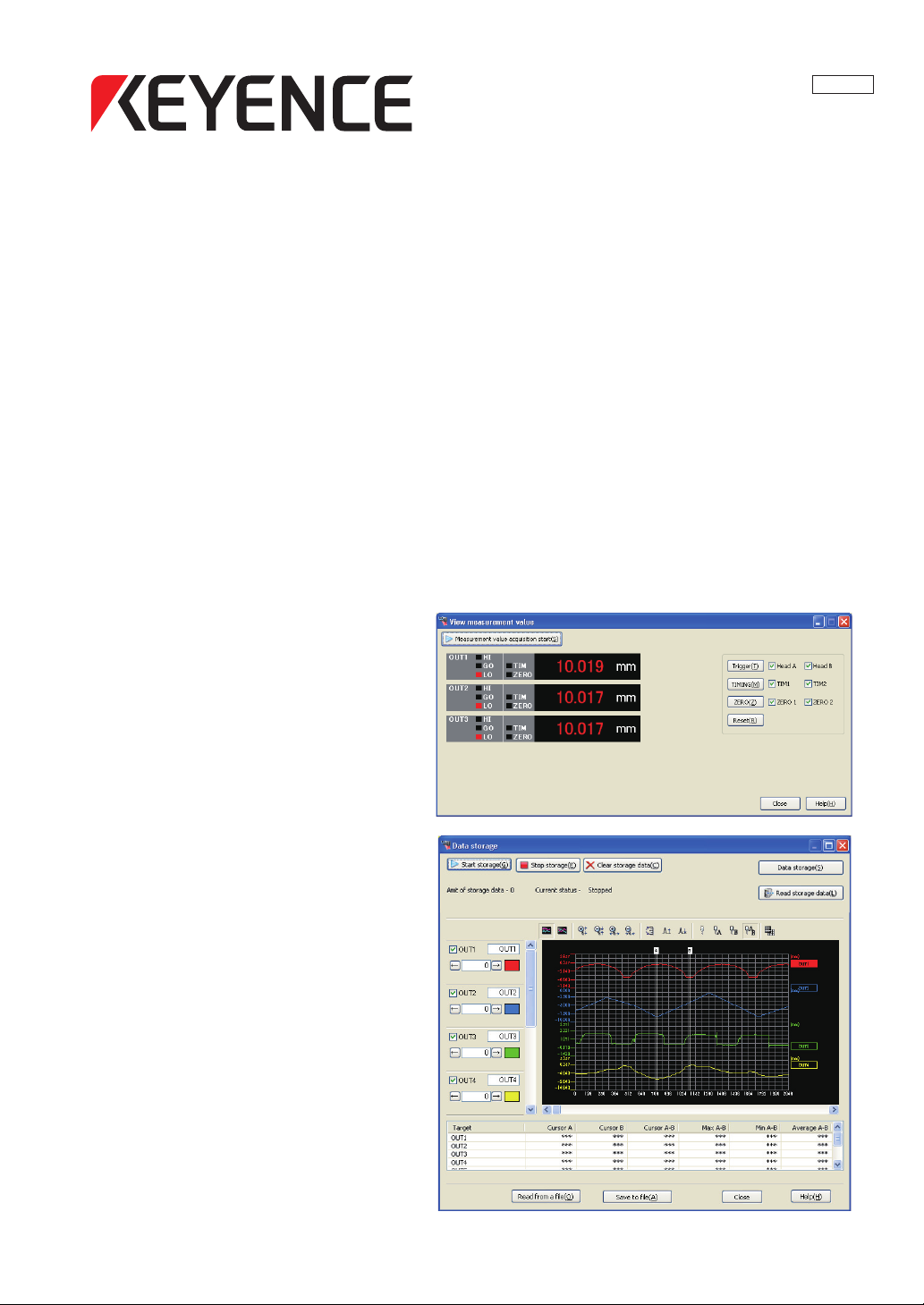
96139E
LJ-Navigator (LJ-H1W)
User's Manual
Setup Support
Software for the LJ-G Series
Read this manual before using the system in order
to achieve maximum performance.
Keep this manual in a safe place after reading it
so that it can be used at any time.
Page 2
Safety Precautions
This manual explains the functions, usage, and configurations for LJ-Navigator (LJ-H1W), the setting and
support software LJ-H1W for the LJ-G Series. Read this manual carefully before starting to use the software to
ensure the optimum performance and full functionality of the LJ-Navigator. Keep this manual in a safe place for
future reference.
Read the LJ-G Series User’s Manual as well as this manual when using the "LJ-Navigator". The controller portion
of the LJ-G Series is referred to as the "controller" in this manual.
Symbols
The following warning symbols are used to alert you to safety precautions and to prevent human injury and/or
damage to property when using this product.
DANGER
Failure to follow these instructions may lead to death or serious injury.
WAR NING
Failure to follow these instructions may lead to injury.
CAUTION
Failure to follow these instructions may lead to damage to this or other units.
Note
Provides additional information on proper operations that can be easily mistaken.
Reference
Provides advanced and useful information for operation.
2
LJ-H1W-M-NO0-E
Page 3

Terms of license agreement on use of the software
Read the following terms of the license agreement before using this software (LJ-H1W).
By using the LJ-Navigator, you signify that you agree with the statements herein.
License agreement
1. License of use
KEYENCE grants you the nonexclusive right to use this software in accordance with terms of this agreement.
2. Copyright
The copyright on the software and supplied documentation belong to KEYENCE Corporation. The user holds
only the license for its use.
3. Prohibited matter
The user may not copy this software and sell or distribute it to a third party. However, when using this software on
a computer that is connected to the KEYENCE product that was purchased with this software, this software may
be installed onto multiple computers for the same company. Also, you may copy this software for the purpose of
keeping backup copy for your personal use.
4. Escape clause
KEYENCE Corporation shall not be held liable by the user or a third party for any damages arising from the use
of the software.
5. Cancellation of contract
KEYENCE may terminate this agreement if you fail to comply with the terms of this agreement. In such event, you
must return the software and all copies to KEYENCE or destroy.
Trademarks
• Windows 2000/XP/Vista/7 are the registered trademarks of Microsoft Corporation, U.S.A.
• Adobe, the Adobe logo, and Reader are the trademarks or registered trademarks of Adobe System
Incorporated in the United States and other countries.
• Other company or product names mentioned in this manual are trademarks or registered trademarks of their
TM
respective companies. The following marks are not used in this manual:
, ®.
LJ-H1W-M-NO0-E
96139E
3
Page 4

Contents
Safety Precautions ...............................................2
Terms of license agreement on use of
the software ..........................................................3
Chapter 1 Getting Started
System Environment ..........................................1-2
Installing LJ-Navigator ........................................1-3
Before Installation .........................................1-3
Uninstalling LJ-Navigator..............................1-4
Installing........................................................1-4
Starting and Exiting LJ-Navigator .......................1-5
Starting..........................................................1-5
Exiting .........................................................1-11
Connecting via USB .........................................1-12
Connecting..................................................1-12
Configuring Communication Settings..........1-13
Installing the USB Driver.............................1-14
Connecting via Ethernet ...................................1-16
Connecting..................................................1-16
Configuring Communication Settings..........1-17
Connecting via RS-232C ..................................1-19
Connecting..................................................1-19
Configuring Communi
cation Settings..........
1-20
Chapter 4 Displaying the
Measurement Data
View Measurement Value .................................. 4-2
Functions and Display .................................. 4-2
View Profile ........................................................ 4-6
Functions and Display .................................. 4-6
Data Storage.................................................... 4-12
Functions and Display ................................ 4-12
Profile Storage ................................................. 4-19
Functions and Display ................................ 4-19
Chapter 5 Setting Each Function
Settings .............................................................. 5-2
Head Settings ............................................... 5-3
Profile Setup................................................. 5-5
Master Registration ...................................... 5-6
Position Correction ....................................... 5-7
OUT Settings ................................................ 5-8
Common Settings ....................................... 5-10
Setting List.................................................. 5-19
Environment Settings ....................................... 5-20
Configuring Settings ................................... 5-20
Chapter 2 Main Window
Main Window ......................................................2-2
Part Names and Functions ...........................2-2
Chapter 3 Operations with the Setting
Files
Reading and Saving Setting Files ......................3-2
Reading and Saving Program Files ..............3-2
Reading and Saving Environment Settings ..3-4
Sending Settings ................................................3-6
Transmit All Settings .....................................3-6
Transmitting One Program
(Single Send/Receive) ..................................3-8
4
Appendix
USB Communication Failure................. Appendix-2
CSV File................................................ Appendix-5
CSV Save Data for Data Storage/
Profile Storage................................. Appendix-5
Error Message List ................................ Appendix-9
Shortcut Key List ................................. Appendix-14
Index ................................................... Appendix-15
LJ-H1W-M-NO0-E
Page 5

Chapter
1
Getting Started
1
Getting Started
This chapter describes installing or uninstalling the
LJ-Navigator, installing the USB driver, and
connecting between the computer and the controller.
System Environment. . . . . . . . . . . . . . . . . . . . . . . . 1-2
Installing LJ-Navigator . . . . . . . . . . . . . . . . . . . . . . 1-3
Starting and Exiting LJ-Navigator . . . . . . . . . . . . . 1-5
Connecting via USB. . . . . . . . . . . . . . . . . . . . . . . 1-12
Connecting via Ethernet. . . . . . . . . . . . . . . . . . . . 1-16
Connecting via RS-232C . . . . . . . . . . . . . . . . . . . 1-19
LJ-H1W-M-NO1-E
1-1
Page 6

System Environment
System Environment
The following system requirements are necessary to use LJ-Navigator.
CPU Pentium III, 400 MHz or higher
Supported OS Windows 7
Windows Vista
Windows XP Professional Edition/Home Edition
Windows 2000 Professional
Memory capacity 128 MB or more
Display XGA (1024 x 768 pixels) or greater, 256 colors or greater
Hard disk
space
Interface
*1 Home Premium, Professional, and Ultimate editions each are supported.
*2 Ultimate, Business, Home Premium, and Home Basic editions each are supported for Windows Vista ver. 1.5 or later.
*3 Select one for communication. Multiple interfaces cannot be used for communication at the same time.
*4 Operations are not guaranteed when connected through a USB hub.
*5 Operations are not guaranteed when connected through a router or a LAN connection.
*3
30 MB or more
Includes one of the following:
USB 2.0/1.1*4, Ethernet*5, RS-232C (Serial port)
*1
*2
1-2
LJ-H1W-M-NO1-E
Page 7

Installing LJ-Navigator
Installing LJ-Navigator
This section describes how to install the LJ-Navigator and USB driver to a computer.
Before Installation
Check the following items before installing.
NoteNote
We recommend making a backup of the master disc in case the CD-ROM becomes damaged.
Free space on the hard disk
LJ-Navigator can only be installed on the hard disk. The hard disk where the software will be installed must
have at least 30 MB of free space. If there is insufficient free space, delete unnecessary items to free the
space.
Pre-installation Windows environment
LJ-Navigator is a Windows application and the software is installed in Windows. Check that Windows 7/Vista/XP/
2000 is installed on the computer and is working properly.
1
Getting Started
Help file
The help file for this software was created in PDF file format. The viewing software Adobe Reader from Adobe
Systems Incorporated must be installed onto your computer to use the help file. You can download the latest
version for free from the Adobe Systems Incorporated web site: http://www.adobe.com
LJ-H1W-M-NO1-E
1-3
Page 8

Installing LJ-Navigator
Installing
This section explains how to install LJ-Navigator using the following drive configuration as an example.
C Drive: Hard disk drive
E Drive: CD-ROM drive
1 Start up Windows and insert the "LJ-Navigator Master Disc" into the CD-ROM drive.
• The installation program automatically starts running. If the installation program does not start up, select
"Run..." from the Start menu. Enter "E:\setup" into the [File name] dialog box and click the [OK] button.
• Install the driver by following the directions on the installation program.
Note
To install, log onto the computer as a user with administrator authority.
LJ-Navigator installation folder
When installing LJ-Navigator with the default settings, the program is installed into the following folder:
C:\Program Files\Keyence\LJ-Navigator\
Uninstalling LJ-Navigator
Use [Add/Remove Programs] from the Windows Control Panel to uninstall LJ-Navigator.
NoteNote
To uninstall "LJ-Navigator", log onto the computer as a user with administrator authority.
1-4
LJ-H1W-M-NO1-E
Page 9
Starting and Exiting LJ-Navigator
Starting and Exiting LJ-Navigator
This section describes how to start and exit "LJ-Navigator".
NoteNote
• Multiple instances of LJ-Navigator cannot be started up at the same time.
• The USB, Ethernet, and RS-232C interfaces on a single controller cannot be used at the same time.
• Communication is disabled when the controller is in the "Setting mode".
Starting
LJ-Navigator starts up in one of the following methods:
• Start up with the default values
• Read from a file
• Read the settings of the connected controller
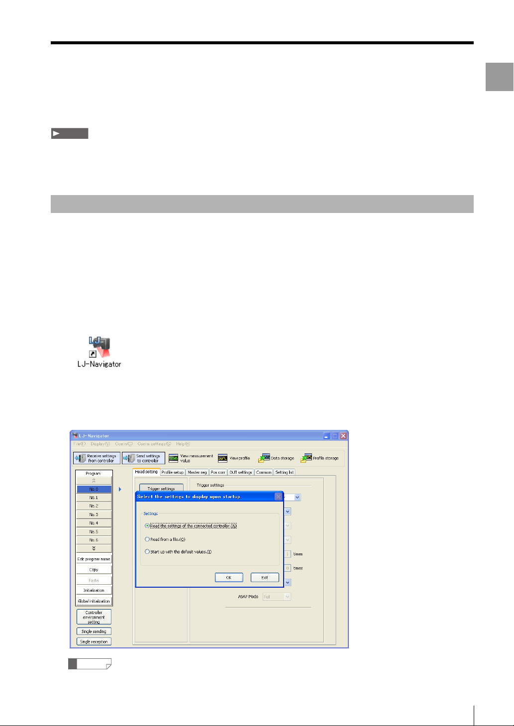
1 Click the [Start] button and then select LJ-Navigator, or double-click on the LJ-Navigator icon on the
desktop.
1
Getting Started
LJ-Navigator starts up. The main screen and the [Select the settings to display upon startup] dialog box are
displayed.
Reference
Click the [Exit] button to exit LJ-Navigator.
LJ-H1W-M-NO1-E
1-5
Page 10
Starting and Exiting LJ-Navigator
When [Start up with the default values] is selected
Select [Start up with the default values] the first time that LJ-Navigator is started up or when creating a new program.
Use the following procedure to start up.
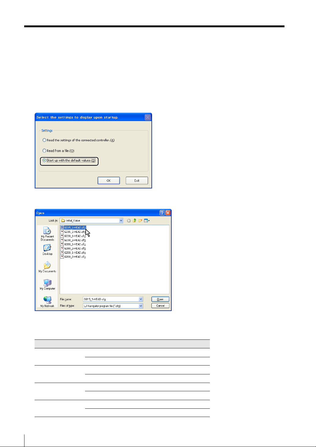
1 Select [Start up with the default values] and click the [OK] button.
2 Select the default startup file to read.
Select one of the following default startup files to read depending on the type and number of heads
connected to the controller.
Type of head No. of units connected File to read
LJ-G015/LJ-G015K 1 unit G015_1-HEAD.cfg
2 units G015_2-HEAD.cfg
LJ-G030 1 unit G030_1-HEAD.cfg
2 units G030_2-HEAD.cfg
LJ-G080 1 unit G080_1-HEAD.cfg
2 units G080_2-HEAD.cfg
LJ-G200 1 unit G200_1-HEAD.cfg
2 units G200_2-HEAD.cfg
LJ-Navigator starts up with the defaults.
1-6
LJ-H1W-M-NO1-E
Page 11
Starting and Exiting LJ-Navigator
When [Read from a file] is selected
When [Read from a file] is selected, LJ-Navigator loads a program file and an environment setting file that
will be saved on the computer.
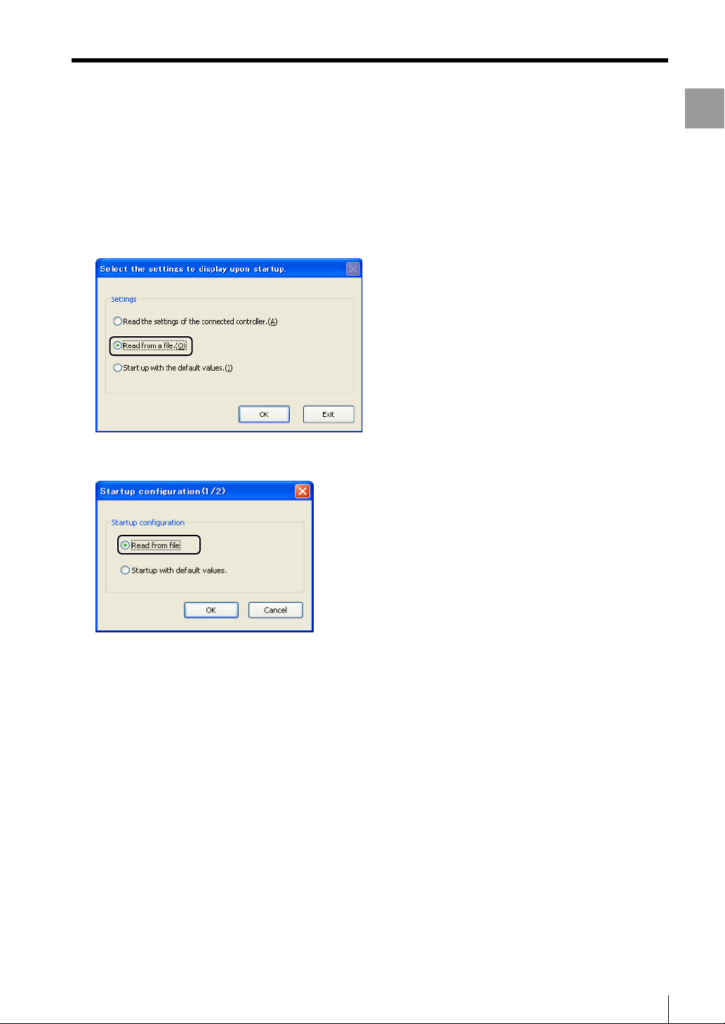
1 Select [Read from a file] and click the [OK] button.
1
Getting Started
The [Startup configuration(1/2)] dialog appears.
2 Select [Read from file] or [Startup with default values].
The following procedure changes depending on whether [Read from file] or [Startup with default values] is
selected.
LJ-H1W-M-NO1-E
1-7
Page 12
Starting and Exiting LJ-Navigator
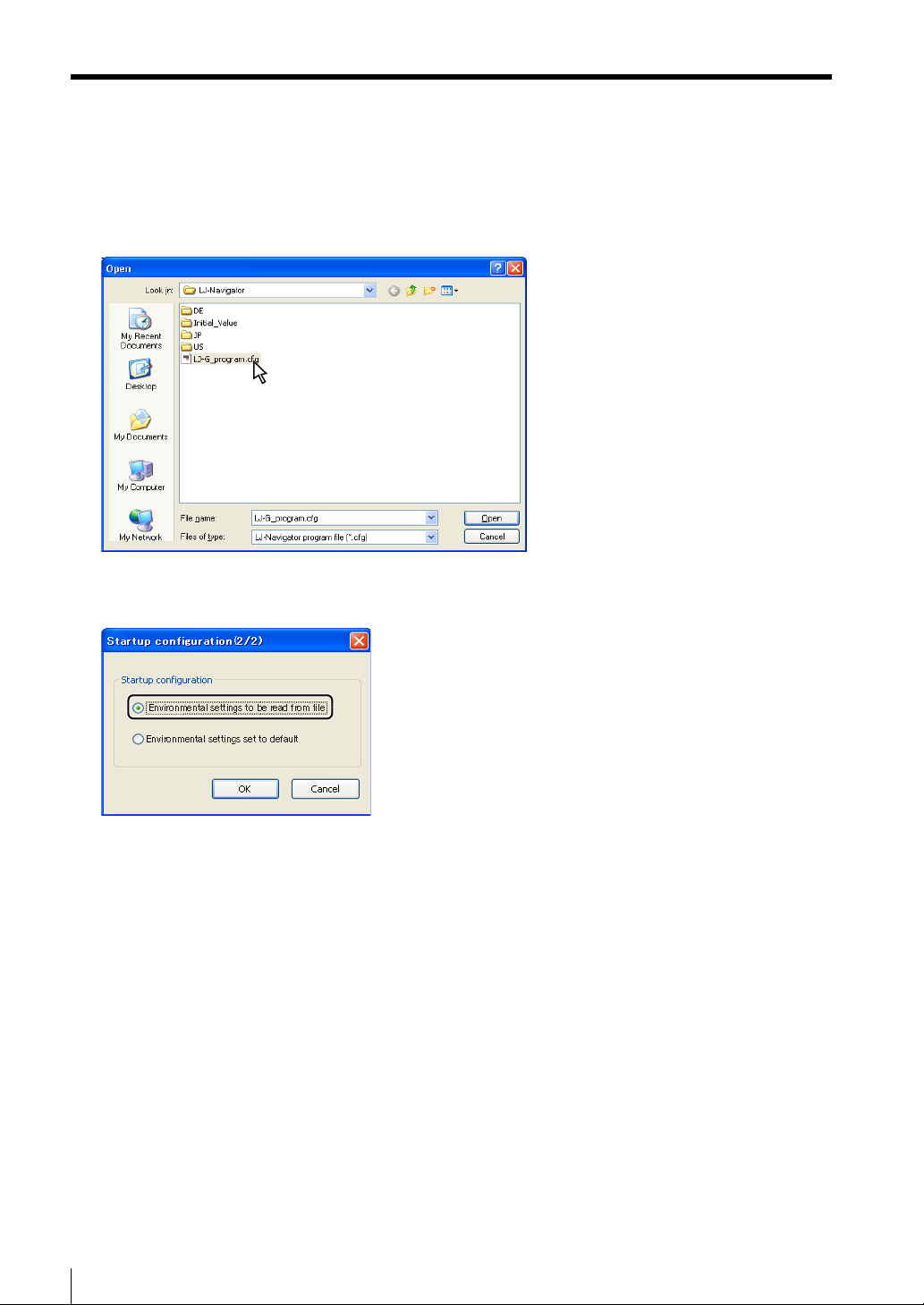
When [Read from file] is selected
Select a program file (*.cfg) to read and click the [Open] button.
The [Startup configuration(2/2)] dialog appears.
Continue to Step 3 (Page 1-10).
1-8
LJ-H1W-M-NO1-E
Page 13
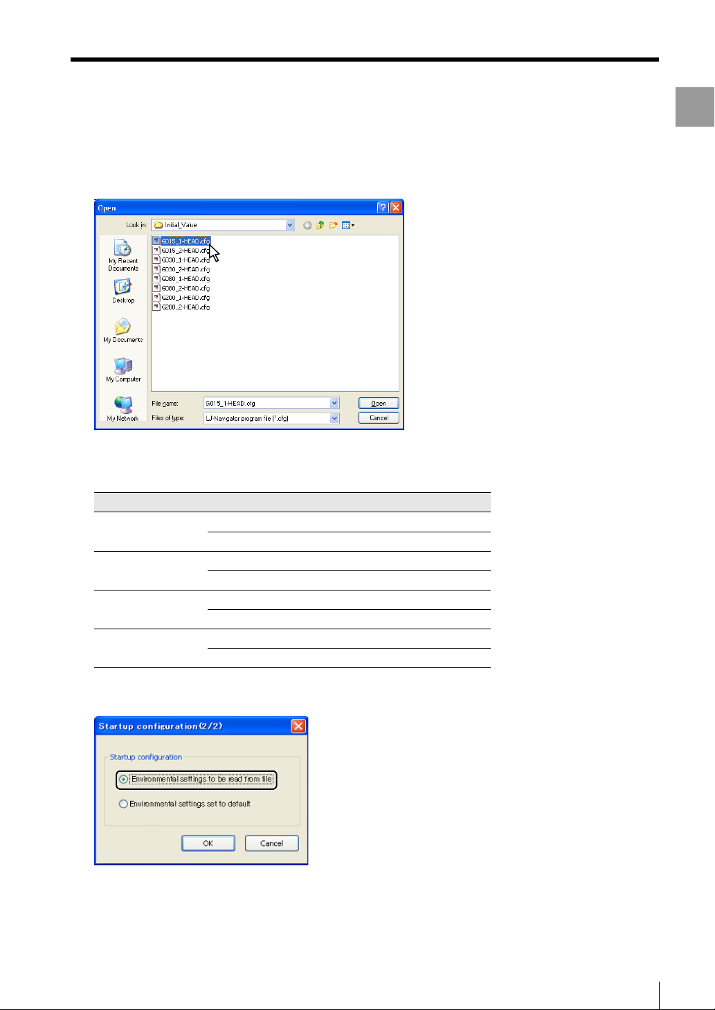
When [Startup with default values] is selected
The [Open] dialog box appears. Select a default startup file to read.
Starting and Exiting LJ-Navigator
1
Getting Started
Select one of the following default startup files to read depending on the type and number of heads
connected to the controller.
Type of head No. of units connected File to read
LJ-G015/LJ-G015K 1 unit G015_1-HEAD.cfg
2 units G015_2-HEAD.cfg
LJ-G030 1 unit G030_1-HEAD.cfg
2 units G030_2-HEAD.cfg
LJ-G080 1 unit G080_1-HEAD.cfg
2 units G080_2-HEAD.cfg
LJ-G200 1 unit G200_1-HEAD.cfg
2 units G200_2-HEAD.cfg
The [Startup configuration(2/2)] dialog appears.
Continue to Step 3 (Page 1-10).
LJ-H1W-M-NO1-E
1-9
Page 14
Starting and Exiting LJ-Navigator
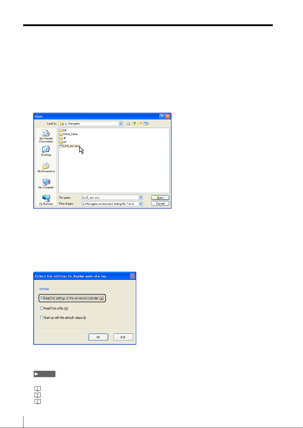
3 Select [Environmental settings to be read from file] or [Environmental settings set to default].
The following procedure changes depending on whether [Environmental settings to be read from file] or
[Environmental settings set to default] is selected.
When [Environmental settings to be read from file] is selected
Select an environment setting file (*.env) to read and click the [Open] button.
LJ-Navigator starts up.
When [Environmental settings set to default] is selected
LJ-Navigator starts up with the defaults.
When [Read the settings of the connected controller] is selected
Select [Read the settings of the connected controller] and click the [OK] button.
The setting files (configuration file and program file) on the connected controller are read
and LJ-Navigator starts up.
Note
In order to read the controller settings, proper communication must be possible between the controller and computer.
"Connecting via USB" (Page 1-12)
"Connecting via Ethernet" (Page 1-16)
"Connecting via RS-232C" (Page 1-19)
1-10
LJ-H1W-M-NO1-E
Page 15
Starting and Exiting LJ-Navigator
Exiting
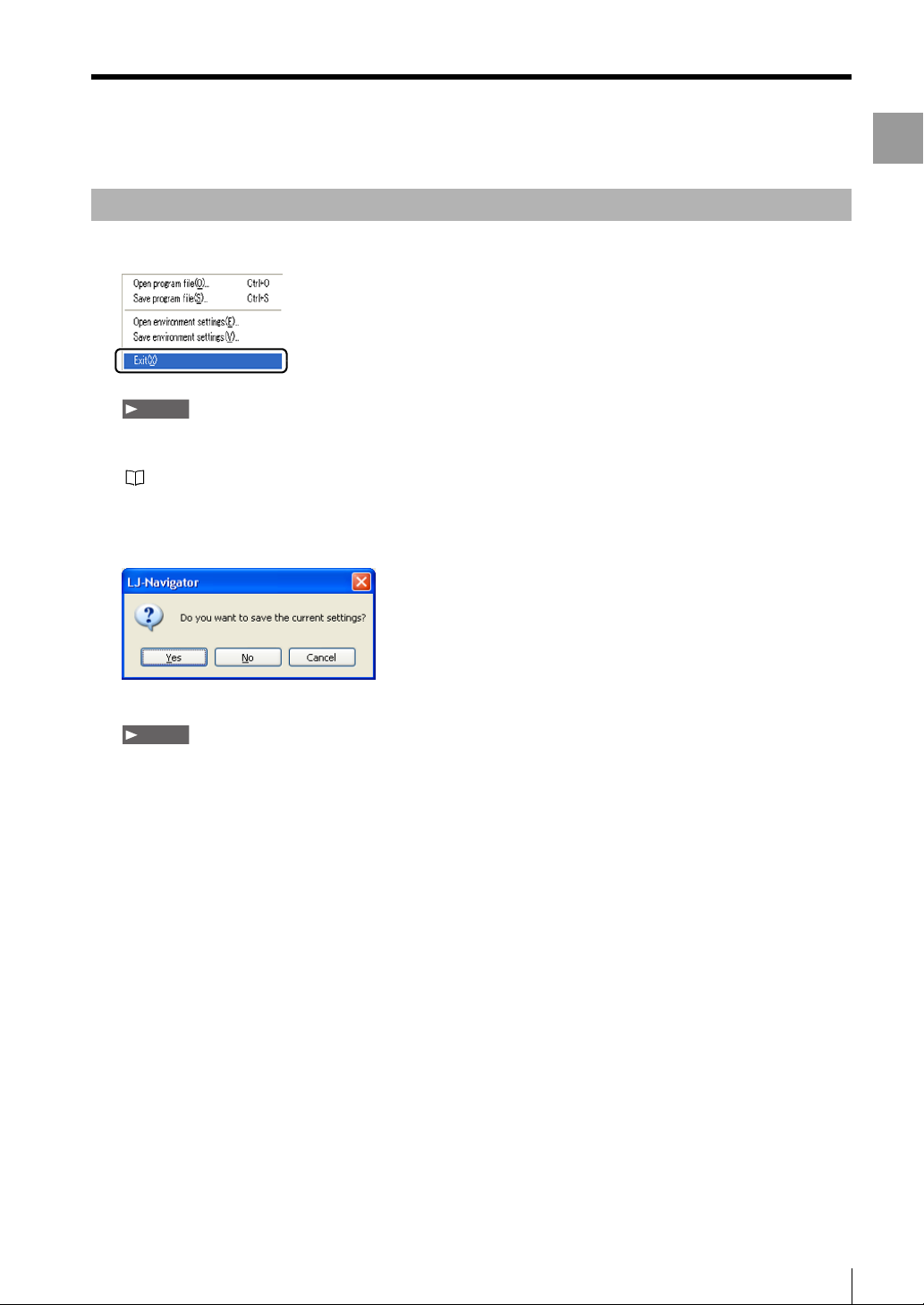
1 Select [Exit] from the [File] menu.
Note
If the settings have been changed, make sure to save the program file and environment setting file before exiting LJNavigator. The changes will be lost if the files are not saved before exiting.
"Reading and Saving Setting Files" (Page 3-2)
If the settings have been changed, a confirmation window appears.
1
Getting Started
Note
Click the [No] button to exit without saving the settings.
LJ-H1W-M-NO1-E
1-11
Page 16
Connecting via USB
Connecting via USB
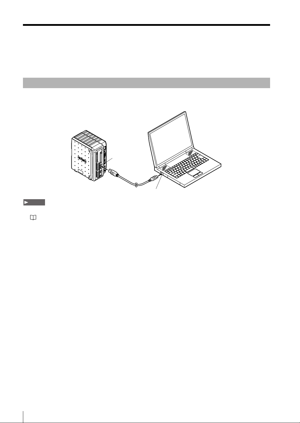
This section describes how to connect the controller to a computer with a USB connection.
Connecting
Use the included USB cable (OP-35331) or another commercial USB cable.
USB connector
USB port
NoteNote
• Install the USB driver when connecting the computer and controller with the USB interface for the first time.
"Installing the USB Driver" (Page 1-14)
• Do not remove the USB cable while the controller is running. Otherwise, the controller may not function correctly. If the
communication is disabled due to accidental disconnection of the USB cable, restart both LJ-Navigator and the controller.
1-12
LJ-H1W-M-NO1-E
Page 17
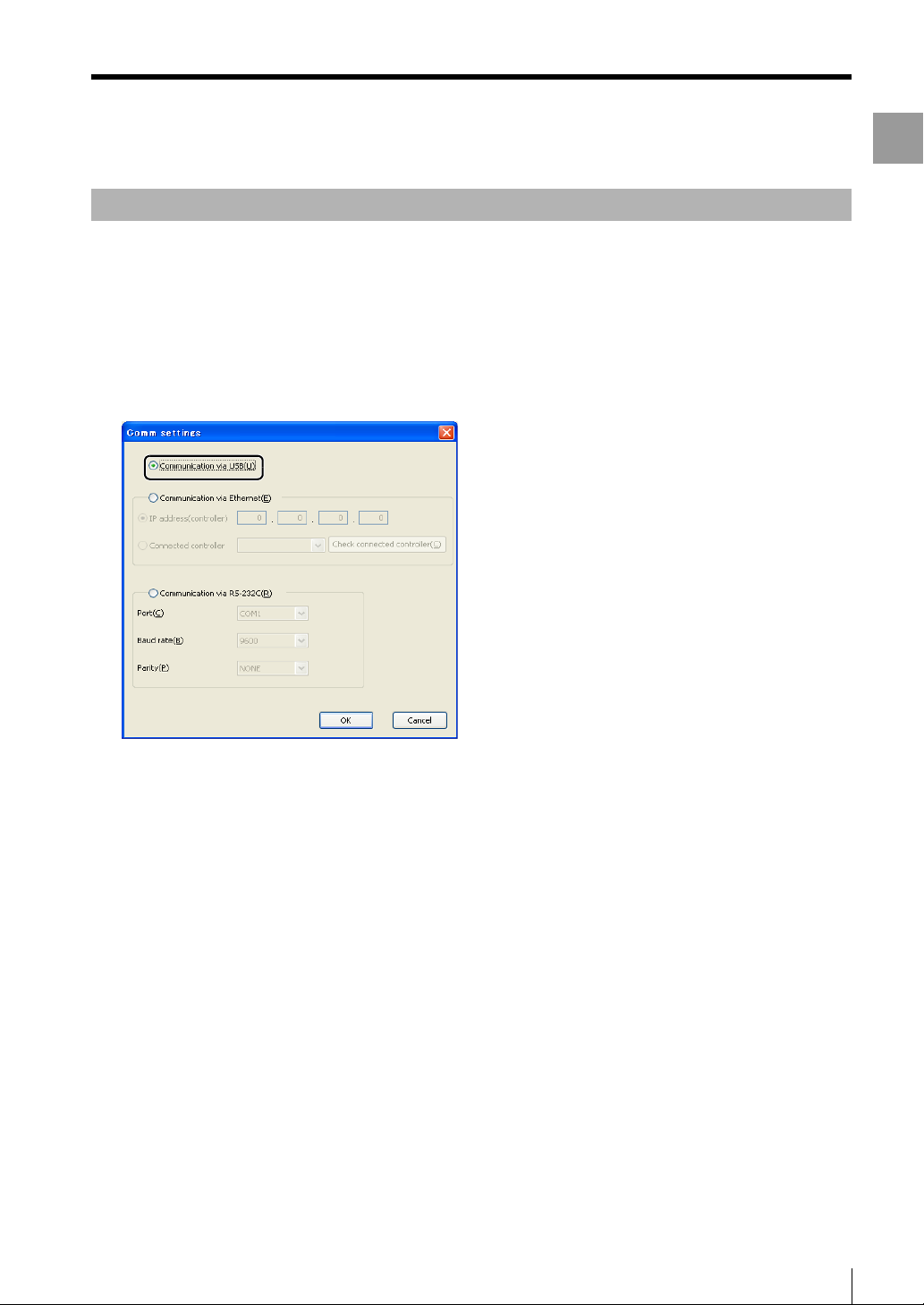
Configuring Communication Settings
1 Start up LJ-Navigator.
2 Select [PC communication setting] from the [Comm settings] menu.
The [Comm settings] dialog appears.
3 Select [Communication via USB] from the [Comm settings] dialog.
Connecting via USB
1
Getting Started
LJ-H1W-M-NO1-E
1-13
Page 18
Connecting via USB
Installing the USB Driver
The driver is installed at the same time as the application software for Windows 7, Vista, XP, and 2000. Normally
following operations are not necessary. If the driver installation is cancelled while installing the application
software, follow the procedure to install the USB driver that is described below.
Installing on Windows XP
Connect the controller to a computer with Windows XP. If the controller is being connected for the first time, the
USB driver for the LJ-G Series must be installed. The connection is automatically recognized after the USB driver
has been installed once and does not need to be installed again.
This section explains how to installed the driver for the LJ-G Series when first connecting to a computer with
Windows XP.
Hardware detection must be performed when installing the USB driver for the LJ-G Series.
Use the following methods to install the driver.
1 Start up Windows XP and log in as a user that has Administrator privileges (or similar privileges that
permit changing system settings).
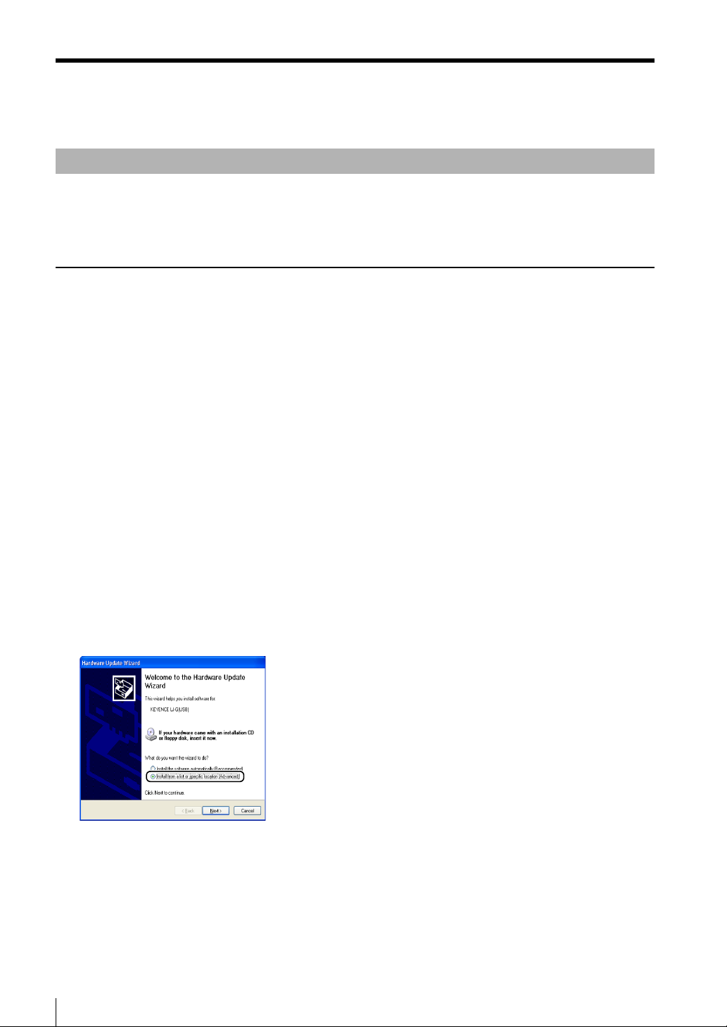
2 Connect the USB port on the computer with the USB port on the LJ-G Series controller with the USB
cable.
The message "Found New Hardware" appears and the Hardware Update Wizard starts up.
3
Select [Install from a list or specific location (Advanced)], and click the [Next] button.
1-14
LJ-H1W-M-NO1-E
Page 19
Connecting via USB
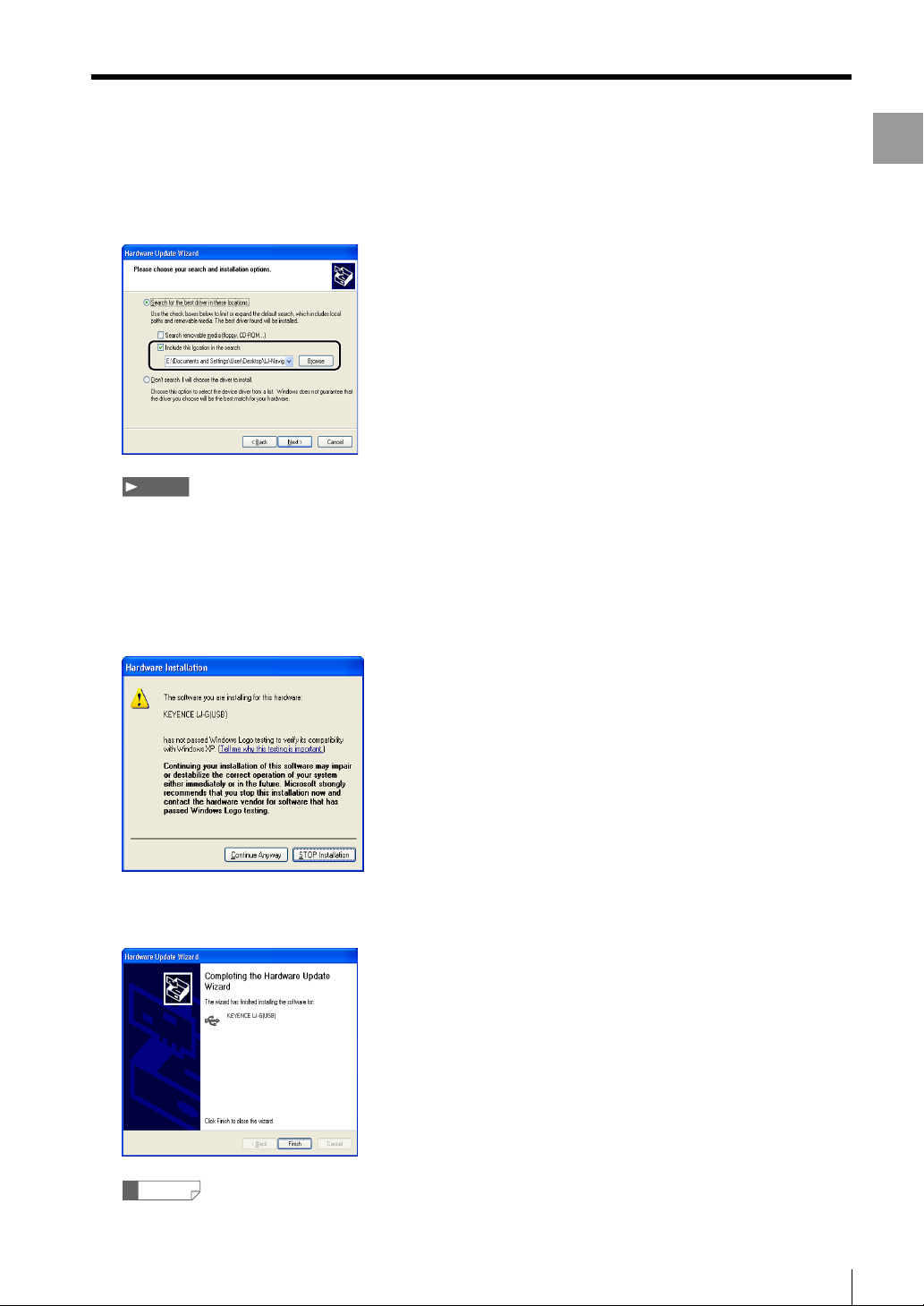
4
Select [Search for the best driver in these locations.] and check the box next to [Include this location in the search:].
Then, enter "C:\Program Files\Keyence\LJ-Navigator" in the text box and click the [Next] button.
Note
"C:\Program Files\KEYENCE\LJ-Navigator" represents the location where LJ-Navigator will be installed. Change the location
depending on the system environment.
1
Getting Started
5 Click the [Continue Anyway] button when the following dialog appears to proceed with installation.
When installation of the USB driver ends successfully, the [Completing the Hardware Update Wizard] dialog
appears.
6 Click the [Finish] button to complete installation of the USB driver.
Reference
The wizard for installing the USB driver may be different when installing onto a computer with a version of Windows other
than Windows XP.
LJ-H1W-M-NO1-E
1-15
Page 20
Connecting via Ethernet
Connecting via Ethernet
This section describes how to connect the controller to a computer with an Ethernet connection. When using
Ethernet communication, one computer can be connected to multiple controllers. One of the connected
controllers can be selected for communication. The communication protocol is TCP/IP, while the connection uses
peer-to-peer communication.
NoteNote
• Configure the settings so that there are different IP addresses used for the computer and each controller on the network.
• Operations are not guaranteed when connected through a router or a separate LAN connection.
• One computer cannot communicate with multiple controllers at the same time.
• Multiple computers cannot be connected to one controller.
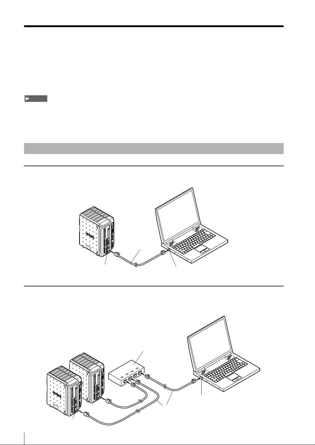
Connecting
Connecting one controller directly to the computer
Use a commercial Ethernet cross cable (CAT 5) (OP-42275) for the connection.
Cross cable
Ethernet connector
Ethernet port
Connecting to two or more controllers
A 100BASE-TX or 10BASE-T hub is required to connect two or more controllers. Use commercial Ethernet
straight cables (OP-42210) to connect between the hub and the computer or controllers.
Hub
Ethernet port
Straight cable
Ethernet connector
1-16
LJ-H1W-M-NO1-E
Page 21

Connecting via Ethernet
Configuring Communication Settings
Set the following communication settings when communicating with Ethernet.
IP address Configure unique addresses for the computer and each controller.
Ex.: When using two controllers and one computer
Controller No. 1 192.168.0.10
Controller No. 2 192.168.0.11
Computer 192.168.0.12
Subnet mask Configure the same settings on the computer and controllers. Use the default
value normally.
(Default: 255.255.255.0)
Default gateway Use the default value normally. (Default: 0.0.0.0)
1 Set the Ethernet settings for the controller.
1
Getting Started
Set the IP address, subnet mask, and default gateway.
For more information about configuring settings, see "LJ-G Series User's Manual".
Note
Restart all of the controllers after configuring the settings to activate the changes to the Ethernet settings.
2 Set the Ethernet settings (TCP/IP) for the computer.
The method for configuring the settings depends on the version of Windows. For more details, see the
instruction manual for the computer or LAN card.
3 Start up LJ-Navigator.
"Starting and Exiting LJ-Navigator" (Page 1-5)
4 Select [PC communication setting] from the [Comm settings] menu.
The [Comm settings] dialog appears.
LJ-H1W-M-NO1-E
1-17
Page 22
Connecting via Ethernet
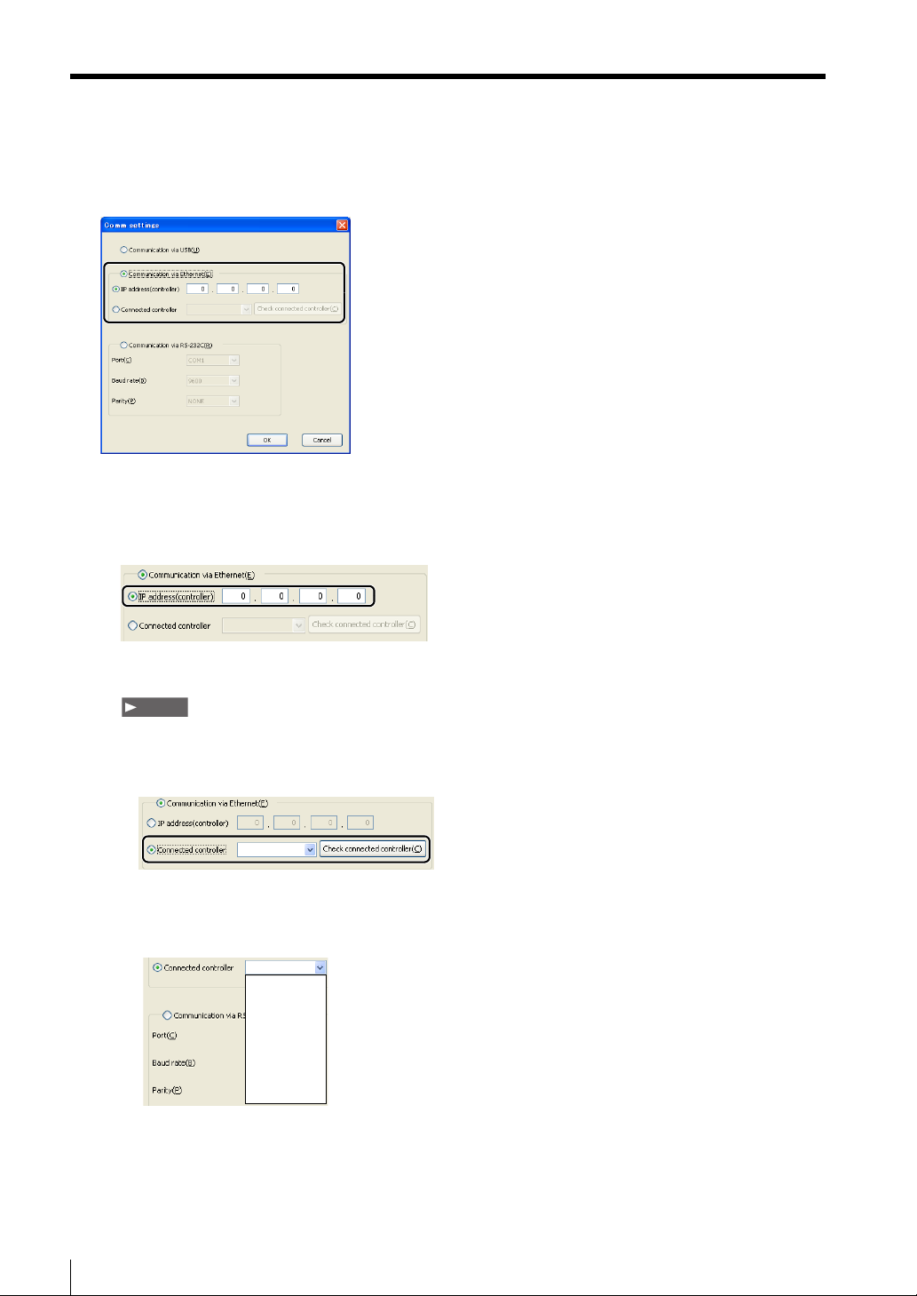
5 Select [Communication via Ethernet] from the [Comm settings] dialog.
1. To enter the IP address for the connected controller directly
Select [IP address (controller)] and enter the IP address for the connected controller.
2. To search for the connected controller
Note
Turn the controller on beforehand and check that it is communicating properly.
• Select [Connected controller] and click the [Check connected controller] button.
• LJ-Navigator automatically searches for the connected controllers and displays the possible IP
addresses in the pull-down menu. Select a controller for communication.
192.168.0.10
192.168.0.11
192.168.0.13
6 Click the [OK] button to close the [Comm settings] dialog.
1-18
LJ-H1W-M-NO1-E
Page 23
Connecting via RS-232C
Connecting via RS-232C
This section explains how to connect the controller to a computer with an RS-232C connection.
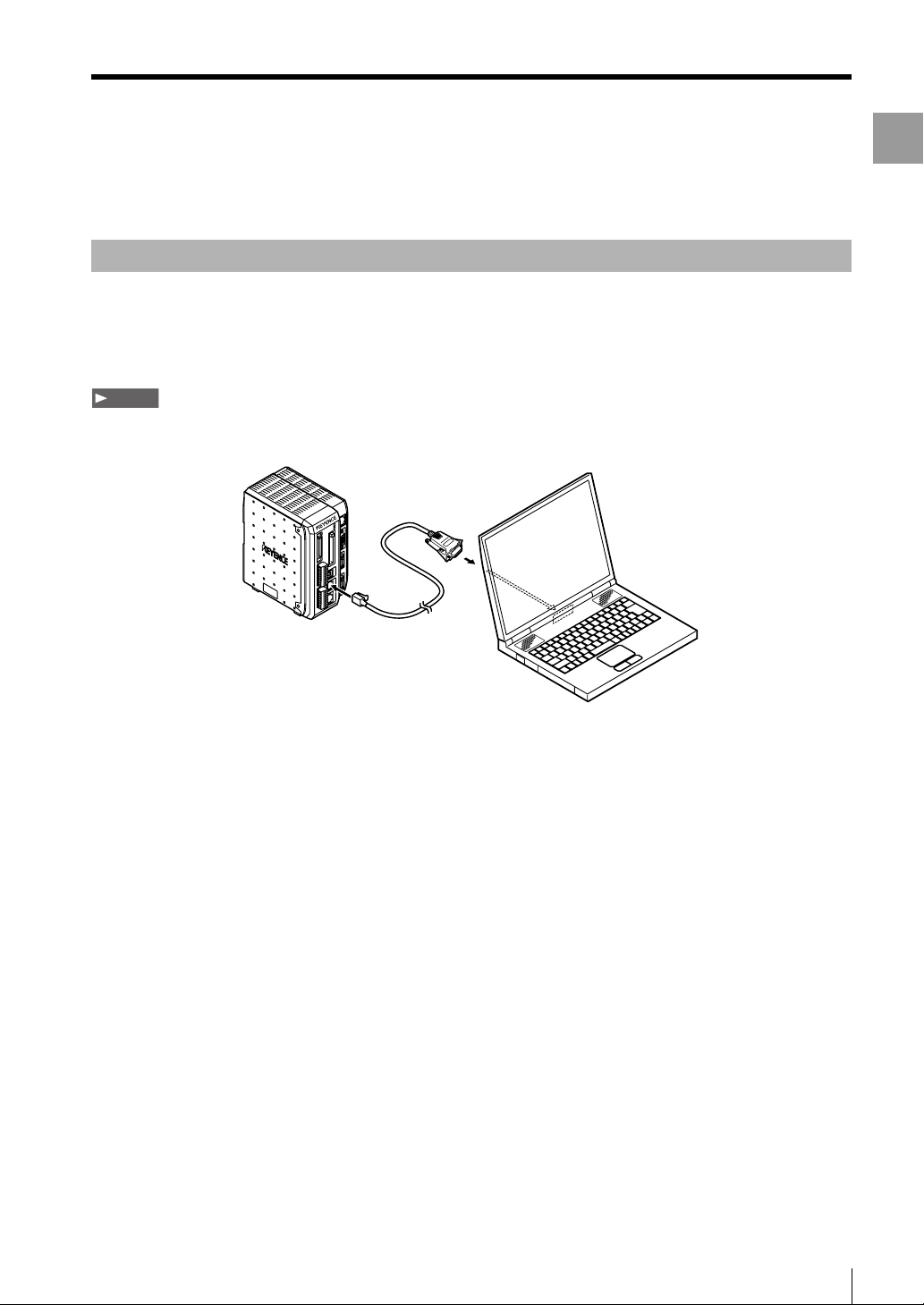
Connecting
To connect the controller to a computer with an RS-232C cable, one of the following dedicated cables is
required: OP-96368 (straight cable 2.5 m), and a port adapter, either OP-26401 (D-sub 9-pin), or OP-96369 (D-
sub 25-pin).
NoteNote
The required cable varies depending on the location and direction of the RS-232C port on the computer. When connecting with
the RS-232C cable, see the instruction manual that comes with the computer.
OP-26401 or
OP-96369
OP-26401
Computer
1
Getting Started
OP-96368
1 Connect the dedicated cable (OP-96368) to the RS-232C connector on the controller.
2 Connect OP-96368 to OP-26401, and then connect to the RS-232C connector on the computer.
This procedure describes an example when using OP-26401 (D-sub 9-pin).
LJ-H1W-M-NO1-E
1-19
Page 24
Connecting via RS-232C
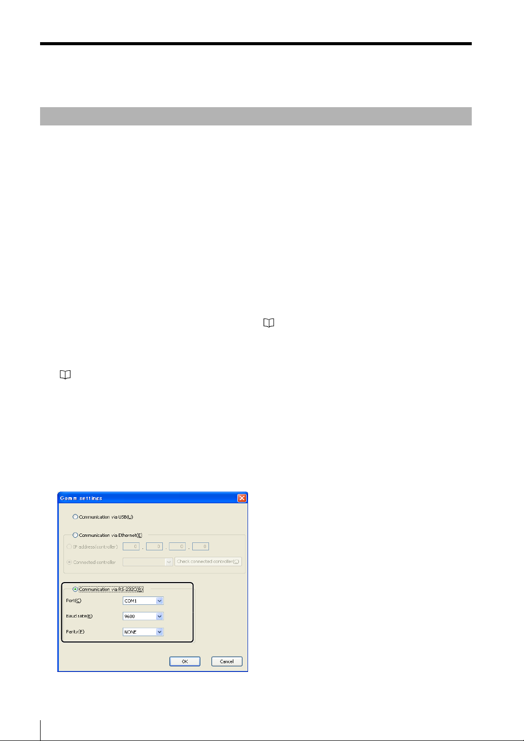
Configuring Communication Settings
When communicating with RS-232C, the communication settings must be the same on the controller and on LJ-
Navigator.
Port Select the port number on the computer where the controller is connected. COM1 to COM8
can be selected on LJ-Navigator.
Baud rate Set the same value for LJ-Navigator and the controller.
Select from 9600, 19200, 38400, 57600, or 115200. Larger values represent faster
communication speeds.
Parity Set the same value for LJ-Navigator and the controller.
Select from NONE, EVEN, and ODD.
Flow control None
1 Configure the settings for RS-232C on the controller.
For more information about configuring settings, see "LJ-G Series User's Manual".
2 Start up LJ-Navigator.
"Starting and Exiting LJ-Navigator" (Page 1-5)
3 Select [PC communication setting] from the [Comm settings] menu.
The [Comm settings] dialog appears.
4 Select [Communicate via RS-232C] and set the communication settings.
Use the same settings that were configured for RS-232C on the controller in Step 1.
5 Click the [OK] button to close the [Comm settings] dialog.
1-20
LJ-H1W-M-NO1-E
Page 25

Chapter
2
Main Window
This chapter describes the names and functions of
each part of the LJ-Navigator main window and how
to operate them.
Main Window . . . . . . . . . . . . . . . . . . . . . . . . . . . . . 2-2
2
Main Window
LJ-H1W-M-NO2-E
2-1
Page 26
Main Window
Main Window
This section describes names and functions of each part of the main window.
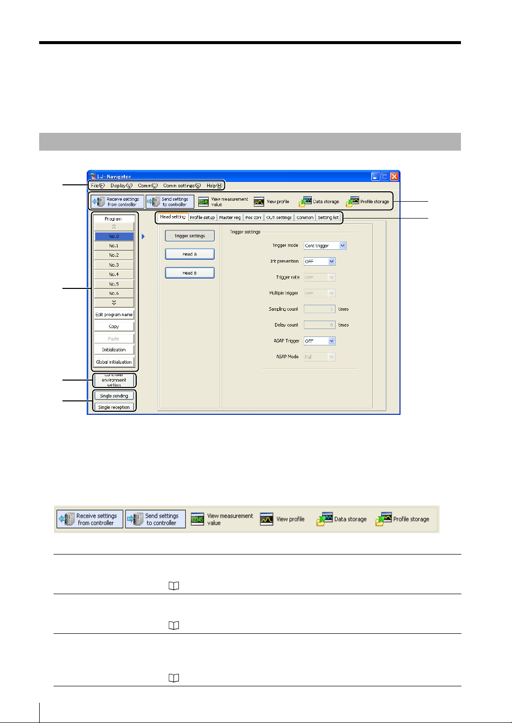
Part Names and Functions
(1)
(3)
(2)
(6)
(4)
(5)
(1) Menu bar
Displays the operational menus for LJ-Navigator.
(2) Tool bar
Displays the buttons for frequently used menus, such as the displays for measurement values and
communication with the controller.
Receive settings from controller LJ-Navigator reads the setting data (program file and environment setting file) that
is saved with the controller.
"Transmit All Settings" (Page 3-6)
Send settings to controller LJ-Navigator writes changed setting data (program file and environment setting
file) to the controller.
"Transmit All Settings" (Page 3-6)
View measurement value Displays the value measured by the LJ-G head on LJ-Navigator.
The displayed data reflects the measurement taken at the time that the [Start
receiving measurement] button is pressed.
"View Measurement Value" (Page 4-2)
2-2
LJ-H1W-M-NO2-E
Page 27
Main Window
View profile Displays the profile measured by the LJ-G head on LJ-Navigator.
reflects the profile taken at the time that the [Start receiving profile] button is clicked.
"View Profile" (Page 4-6)
Data storage Configures the settings for storing measurement data in the controller.
Stored data can be displayed on LJ-Navigator or saved as a csv file on the
computer.
"Data Storage" (Page 4-12)
Profile storage Configures the settings for storing the measured profile in the controller.
Stored profiles can be displayed on LJ-Navigator or saved as a csv file on the computer.
"Profile Storage" (Page 4-19)
The displayed data
(3) Setting and operation area for program settings
Allows the settings to be changed for other programs, and also includes the initializing, copying and
program naming functions.
"Setting and operation area for program settings" (Page 2-4)
(4) Controller environment setting
Configures settings such as user operations and communication conditions for the controller.
"Environment Settings" (Page 5-20)
(5) Single sending/reception
Sends or receives a single program No. between LJ-Navigator and the controller.
"Transmitting One Program (Single Send/Receive)" (Page 3-8)
2
Main Window
Note
• This option is only active if "Communicate via RS-232C" is selected under "Comm settings" in LJ-Navigator.
"Connecting via RS-232C" (Page 1-19)
• When sending or receiving a single program, the environment setting file is not transmitted.
(6) Program setting area
Sets the measurement conditions for each program. The tabs toggle between each setting.
• Head setting....................... "Head Settings" (Page 5-3)
• Profile setup ....................... "Profile Setup" (Page 5-5)
• Master reg.......................... "Master Registration" (Page 5-6)
• Pos corr.............................. "Position Correction" (Page 5-7)
• OUT settings ...................... "OUT Settings" (Page 5-8)
• Common............................. "Common Settings" (Page 5-10)
• Setting list........................... "Setting List" (Page 5-19)
Reference
For more information about each setting, see "LJ-G Series User's Manual".
LJ-H1W-M-NO2-E
2-3
Page 28
Main Window
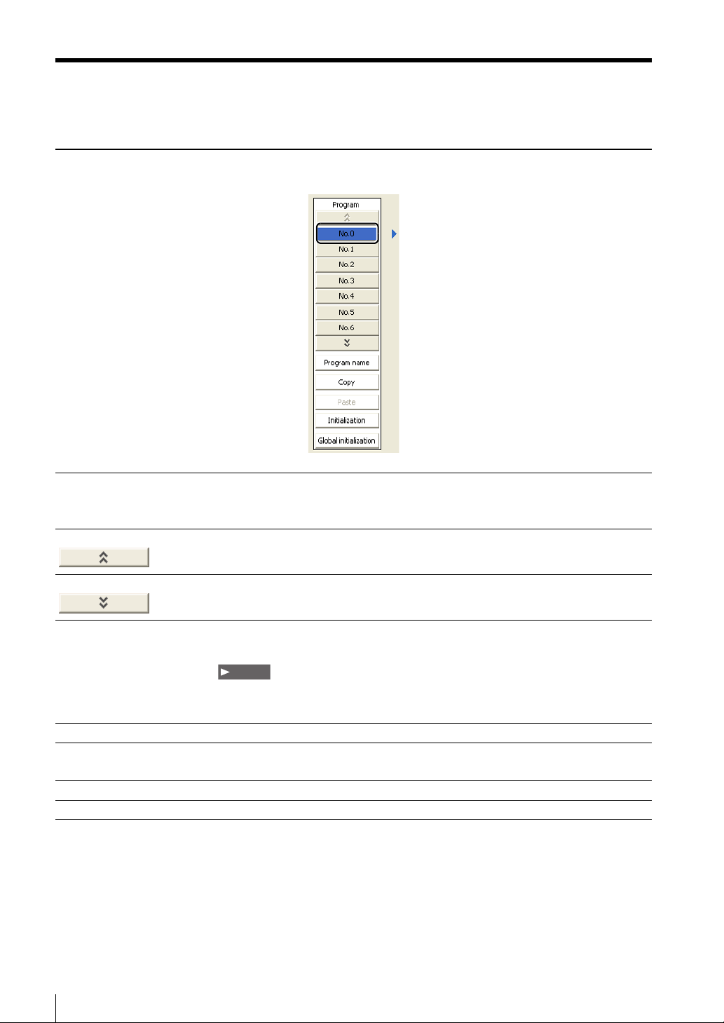
Setting and operation area for program settings
No. 0 to No. 15 The settings for the selected program No. can be checked and changed.
Clicking on the selected program No. changes the color of the button to blue to show
that this is the program currently in use in LJ-Navigator.
Up arrow button Clicking on this button displays the preceding program No.
Down arrow button Clicking on this button displays the following program No.
Program name Clicking on this button displays the [Program name] dialog. Set the program name in
this dialog box.
Note
•
Enter up to 16 characters for the program name.
•
Letters and numbers can be used for the program name.
Copy Copies the settings* in the currently selected program No. for pasting.
Paste
Initialize Initializes the settings* in the currently selected program No.
Global initialization Initializes the settings
Pastes the settings* that were copied by using the [Copy] button into the program No. that
is being edited.
*
for all of the program Nos. 0 to 15.
* "Copy", "Paste", and "Initialize" act on the following settings:
• Head settings
• Profile settings
• Master registration
• Position correction
• OUT settings
• Common settings
2-4
LJ-H1W-M-NO2-E
Page 29

Chapter
3
Operations with the Setting
Files
This chapter describes receiving, loading, saving,
and sending setting files.
Reading and Saving Setting Files . . . . . . . . . . . . . 3-2
Sending Settings . . . . . . . . . . . . . . . . . . . . . . . . . . 3-6
3
Operations with the Setting Files
LJ-H1W-M-NO3-E
3-1
Page 30
Reading and Saving Setting Files
Reading and Saving Setting Files
There are two types of setting files used by LJ-Navigator: program files (*.cfg) and environment setting files (*.env).
This section describes how to read setting files from the computer and save files to the computer. (Program files
and environment setting files are managed separately)
Reference
Program files include all of the settings in program Nos. 0 to 15.
Reading and Saving Program Files
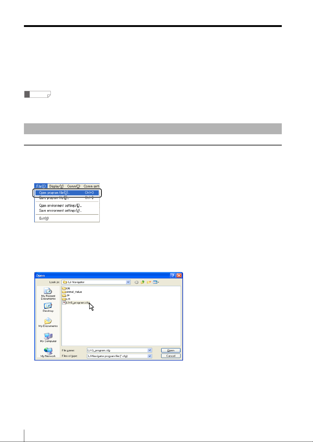
Reading program files
1 Select [Open program file] from the [File] menu.
The [Open] dialog appears.
2 Select a program file (*.cfg) to read and click the [Open] button.
The program file is read.
3-2
LJ-H1W-M-NO3-E
Page 31

Saving program files
1 Select [Save program file] from the [File] menu.
The [Save As] dialog appears on the screen.
2 Enter a file name and click on the [Save] button.
The program file is saved.
Reading and Saving Setting Files
3
Operations with the Setting Files
Note
If a previously saved program file exists with the same name, the file is overwritten.
LJ-H1W-M-NO3-E
3-3
Page 32

Reading and Saving Setting Files
Reading and Saving Environment Settings
Reading environment settings
1 Select [Open environment settings] from the [File] menu.
The [Open] dialog appears.
2 Select an environment setting file (*.env) to read and click the [Open] button.
The environment setting file is read.
3-4
LJ-H1W-M-NO3-E
Page 33

Saving environment settings
1 Select [Save environment settings] from the [File] menu.
The [Save As] dialog appears on the screen.
2 Enter a file name and click on the [Save] button.
The environment settings are saved.
Reading and Saving Setting Files
3
Operations with the Setting Files
Note
If a previously saved environment setting file exists with the same name, the file is overwritten.
LJ-H1W-M-NO3-E
3-5
Page 34

Sending Settings
Sending Settings
This section describes how to transmit all settings or a single program between LJ-Navigator and the controller.
Settings that are changed in LJ-Navigator are reflected to the controller immediately after being sent. Settings
from the controller are reflected to LJ-Navigator immediately after being received.
Transmit All Settings
This function transmits the following data to the controller.
•
All of the settings for program No. 0 to 15 (Head settings, Profile settings, Master registration, Position correction,
OUT settings, Common settings)
• Controller environment settings
Sending all settings
1 Connect LJ-Navigator and the controller, and check that communication is normal.
"Connecting via USB" (Page 1-12)
"Connecting via Ethernet" (Page 1-16)
"Connecting via RS-232C" (Page 1-19)
2 Click the [Send settings to controller] icon in the tool bar.
Or, select [Send the settings to the controller] from the [Comm] menu.
The [During communication...] dialog appears.
The dialog closes when sending the settings is complete.
3-6
LJ-H1W-M-NO3-E
Page 35

Receiving all settings
Sending Settings
1 Connect LJ-Navigator and the controller, and check that communication is normal.
"Connecting via USB" (Page 1-12)
"Connecting via Ethernet" (Page 1-16)
"Connecting via RS-232C" (Page 1-19)
2 Click the [Receive settings from controller] icon of the tool bar.
Or, select [Receive the settings from the controller] from the [Comm] menu.
The [During communication...] dialog appears.
The dialog closes when receiving the settings is complete.
3
Operations with the Setting Files
LJ-H1W-M-NO3-E
3-7
Page 36

Sending Settings
Transmitting One Program (Single Send/Receive)
This function transmits a single setting (head settings, profile settings, master registration, position correction,
OUT settings, common settings) for the selected program number.
The transmission speed is faster than transmitting all of the settings.
NoteNote
• This function is active when the controller and computer are connected with an RS-232C connection (when RS-232C is
selected for the communication setting).
• The environment settings for the controller are not transmitted.
Sending one program
1 Connect LJ-Navigator and the controller with RS-232C, and check that communication can be
established.
"Connecting via RS-232C" (Page 1-19)
2 Select the program No. to send.
Select the program No. to send.
3-8
LJ-H1W-M-NO3-E
Page 37

3 Click the [Single sending] icon of the program transmission icons.
Or, select [Single sending] from the [Comm] menu.
The [During communication...] dialog appears.
The dialog closes when sending the settings is complete.
Sending Settings
3
Operations with the Setting Files
LJ-H1W-M-NO3-E
3-9
Page 38

Sending Settings
Receiving one program
1 Connect LJ-Navigator and the controller with RS-232C, and check that communication can be
established.
"Connecting via RS-232C" (Page 1-19)
2 Select the program No. to receive from the controller.
Select the program No.
to receive from the controller.
3 Click the [Single reception] icon of the program transmission icons.
Or, select [Single reception] from the [Comm] menu.
The [During communication...] dialog appears.
The dialog closes when receiving the settings is complete.
3-10
LJ-H1W-M-NO3-E
Page 39

Chapter
4
Displaying the
Measurement Data
This chapter describes how to display and operate
the different kinds of measurement data that are
measured by the controller.
View Measurement Value . . . . . . . . . . . . . . . . . . . . 4-2
View Profile. . . . . . . . . . . . . . . . . . . . . . . . . . . . . . . 4-6
Data Storage . . . . . . . . . . . . . . . . . . . . . . . . . . . . 4-12
Profile Storage . . . . . . . . . . . . . . . . . . . . . . . . . . . 4-19
4
Displaying the Measurement Data
LJ-H1W-M-NO4-E
4-1
Page 40

View Measurement Value
View Measurement Value
This section describes displaying the values measured with the controller in real time on the LJ-Navigator.
Functions and Display
The values measured by the controller can be displayed in real time in the [View measurement value] window.
Measurement controls such as a trigger, timing, zero and reset input can also be performed on the controller.
(1)
(3)
(2)
(4)
(1)[Measurement value acquisition start] button
Displays the values being measured by the controller in real time on LJ-Navigator.
Displayed after the measurement values has been completed. Click this button to start
:
receiving measurement values.
:
Displayed while the measurement values are being received.
measurement to stop receiving the values.
Click this button during
(2)Measurement value display
Displays the measurement result from the controller for each OUT setting.
The values for all of the OUT settings (OUT1 to OUT8) that are set on the controller are displayed.
Measured value
Timing/zero display
Tolerance comparator output
(5)
4-2
LJ-H1W-M-NO4-E
Page 41

(3)Measurement control
Inputs a control signal into the connected controller.
[Trigger] button Inputs a trigger to the specified head.
: When inputting a trigger to only Head A
: When inputting a trigger to only Head B
: When inputting a trigger to both Head A and Head B
[TIMING] button Inputs a TIMING input to the specified TIM.
Assign the TIMING input for each OUT setting by using the [Common] tab.
: When inputting TIMING on only TIM1
: When inputting TIMING on only TIM2
: When inputting TIMING on both TIM1 and TIM2
View Measurement Value
4
Displaying the Measurement Data
[ZERO] button Inputs an auto-zero for the specified ZERO.
Assign the ZERO input for each OUT setting by using the [Common] tab.
: When inputting auto-zero on only ZERO1
: When inputting auto-zero on only ZERO2
: When inputting auto-zero on both ZERO1 and ZERO2
[Reset] button Resets the measured values that are displayed.
Reference
For more information about each control signal, see "LJ-G Series User's Manual".
(4)[Close] button
Closes the [View measurement value] window.
(5)[Help] button
Opens the help function for LJ-Navigator.
LJ-H1W-M-NO4-E
4-3
Page 42

View Measurement Value
Operating the [View measurement value] window
1 Connect LJ-Navigator and the controller, check that communication can be established, and then
measure the measurement target.
"Connecting via USB" (Page 1-12)
"Connecting via Ethernet" (Page 1-16)
"Connecting via RS-232C" (Page 1-19)
2 Click the [View measurement value] icon of the tool bar.
The [View measurement value] window appears.
[View measurement value] icon
Alternative procedures
• Select [View measurement value] from the [Display] menu.
• Press the F5 key.
4-4
LJ-H1W-M-NO4-E
Page 43

View Measurement Value
3 Click the [Measurement value acquisition start] button.
The measurements for the OUT settings that are configured in the controller appear in the window.
[Measurement value acquisition start] button
4
Displaying the Measurement Data
Reference
• If communication is not possible between LJ-Navigator and the controller, or if a head is not connected, the following dialog
appears shortly after clicking the [Measurement value acquisition start] button or [Trigger] button.
Check the connection between each head and between LJ-Navigator and the controller.
• For more information about the OUT settings, see "LJ-G Series User's Manual".
LJ-H1W-M-NO4-E
4-5
Page 44

View Profile
View Profile
This section describes displaying the profiles that are measured with the controller in real time on the LJ-
Navigator.
Functions and Display
The profiles measured by the controller can be displayed in real time in the [View profile] window.
(2)
(1)
(4)
(7)
(8)
(3)
(5)
(6)
(11)
(10)(9)
(1)[Profile acquisition start] button
Displays the profiles being measured by the controller in real time on LJ-Navigator.
: Displayed after profiling has been completed. Click this button to start receiving
profiles that are being measured.
: Displayed while profiling. Click this button during measurement to stop receiving
the profiles.
4-6
LJ-H1W-M-NO4-E
Page 45

(2)[Display profile] button
The [Display profile] dialog box appears. The settings for displayed profiles can be configured.
Display profile Select the profile to display.
ProfileA .........................Displays the profile measured by Head A.
ProfileB .........................Displays the profile measured by Head B.
ProfileAB.......................Displays the profile measured by Head A and Head B.
The display method can be selected.
Calc profile ...................Display the profile that results from adding Profile A and Profile B.
View Profile
4
Displaying the Measurement Data
NoteNote
When "Calculation" is selected for the profile setting and junction (vertical) or junction (horizontal) is
selected, select "ProfileAB" for the display profile.
Display method Select the display method for the profile.
The display method can only be changed when [ProfileAB] is selected in [Display profile].
1 screen display
Vertical 2 screen display Width 2 screen display
LJ-H1W-M-NO4-E
4-7
Page 46

View Profile
(3)[Trigger] button
Inputs a trigger to the selected head.
For more information about triggers, see "LJ-G Series User's Manual".
(4)View profile toolbar
Performs operations on the displayed profile.
When displayed in split screen, the profile for the selected head is edited.
Vertical zoom in This button zooms in on the displayed profile in the vertical direction.
Vertical zoom out This button zooms out on the displayed profile in the vertical direction.
Horizontal zoom in This button zooms in on the displayed profile in the horizontal direction.
Horizontal zoom out This button zooms out on the displayed profile in the horizontal direction.
Default display This button returns the displayed profile to the default display size.
Horizontal cursor This button displays the horizontal cursor on the view profile area.
Vertical cursor This button displays the vertical cursor on the view profile area.
Hide cursor This button hides the cursor.
View master profile This button displays the registered master profile on top of the displayed
profile.
(5)View profile area
Displays the profile that is received from the controller.
(6)Cursor information
Displays the information from the cursor that is displayed in the view profile area.
(7)[Copy screenshot] button
Copy the displayed profile to the clipboard.
The copied profile can be pasted into another application as an image. When displayed in split screen, the
profile for the selected head is copied.
4-8
LJ-H1W-M-NO4-E
Page 47

(8)[Double-writing the profiles] button
Clicking the [Double-writing the profiles] button freezes the profile that was displayed in the profile display
area. Then, the acquired profile is displayed on top of the frozen profile.
Profile that was displayed when the
[Double-writing the profiles] button
was clicked
New profile that is being received
View Profile
4
Displaying the Measurement Data
(9)[CSV output] button
Clicking the [CSV output] button saves the profile as a file in CSV format.
(10)[Close] button
Closes the [View profile] window.
(11)[Help] button
Opens the help function for LJ-Navigator.
LJ-H1W-M-NO4-E
4-9
Page 48

View Profile
Operating the [View profile] window
1 Connect LJ-Navigator and the controller, check that communication can be established, and then
measure the measurement target to obtain a profile.
"Connecting via USB" (Page 1-12)
"Connecting via Ethernet" (Page 1-16)
"Connecting via RS-232C" (Page 1-19)
2 Click the [View profile] icon of the tool bar.
[View profile] icon
Alternative procedures
• Select [View profile] from the [Display] menu.
• Press the F6 key.
4-10
LJ-H1W-M-NO4-E
Page 49

3 Click the [Profile acquisition start] button.
The profiles that are received from the controller appear in the [View profile] window.
[Profile acquisition start] button
View Profile
4
Displaying the Measurement Data
Reference
• If communication is not possible between LJ-Navigator and the controller, or if a head is not connected, the following dialog
appears shortly after clicking the [Profile acquisition start] button or [Trigger] button.
Check the connection between each head and between LJ-Navigator and the controller.
• For more information about profile display, see "LJ-G Series User's Manual".
LJ-H1W-M-NO4-E
4-11
Page 50

Data Storage
)
)
Data Storage
Data storage is a function for setting up and storing measurement data in the internal memory of the controller.
Functions and Display
In the [Data storage] window, measurement data that is stored in the controller can be loaded and saved as a file.
The settings for data storage and directions for starting or stopping measurement data acquisition can be
changed.
(1)
(6)
(7)
(9)
(2)
(3)
(4)
(5)
(8)
(10
(11
(12)
(1)[Start storage] button
Starts storing the measurement data from the controller.
(2)[Stop storage] button
Stops storing the measurement data from the controller.
4-12
(14)(13)
(15)
LJ-H1W-M-NO4-E
Page 51

Data Storage
(3)[Clear storage data] button
Clears all of the measurement data from all of the OUT settings that are stored in the internal memory of the
controller.
(4)[Data storage] button
Displays the [Data storage] dialog box.
This dialog box can be used to configure the controller’s data storage settings.
Amt of data Sets the amount of data points to store.
Setting range: 1 to 65536
Skipping Sets the number of points to skip from the stored data points.
Setting range: 1/2/5/10/20/50/100
All reception Receives all of the storage settings (program Nos. 0 to 15 and environment settings)
from the controller.
Single reception Receives the storage settings from a single, selected program No.
All transmission Sends all of the storage settings (program Nos. 0 to 15 and environment settings)
from LJ-Navigator to the controller.
Single sending Sends the storage settings from a single, selected program No.
Close Closes the [Data storage] dialog box.
4
Displaying the Measurement Data
(5)[Read storage data] button
Reads the data that is stored in the connected controller on LJ-Navigator.
(6)Amount of storage data
Displays the amount of data that is stored on the controller.
(7)Current status
Displays the current operation status for the controller.
LJ-H1W-M-NO4-E
4-13
Page 52

Data Storage
(8)Data storage toolbar
Performs operations on the displayed graph of stored data.
Stack graphs
Overlap graphs
Vertical zoom in This button zooms in on the displayed profile in the vertical direction.
Vertical zoom out This button zooms out on the displayed profile in the vertical direction.
Horizontal zoom in This button zooms in on the displayed profile in the horizontal direction.
Horizontal zoom out This button zooms out on the displayed profile in the horizontal direction.
Automatic scaling
Raise display position
Lower display position
When there are multiple OUT settings for stored data, the graphs for the
OUT settings are displayed one above each other.
When there are multiple OUT settings for stored data, the graphs for the
OUT settings are displayed on top of each other.
This button automatically changes the vertical width of the graph to fill
the current size of the [Data storage] window.
This button moves the graph upwards when the data extends beyond
the view graph area.
This button moves the graph downwards when the data extends beyond
the view graph area.
4-14
Hide cursor This button hides the cursor.
View cursor A This button allows cursor A to be operated in the view profile area.
View cursor B This button allows cursor B to be operated in the view profile area.
View cursor A&B
Change graph background
color
This button allows cursor A and cursor B to be operated in the view
profile area.
This button changes the color of the background on the view graph
area.
LJ-H1W-M-NO4-E
Page 53

(9)Graph display information for each OUT setting
Changes the graph display for each OUT setting.
Data Storage
Switches between showing and hiding the graph.
Check this checkbox to display the graph.
Displays the name of the graph. The name can be changed.
Moves the graph in the horizontal direction.
Displays the color used for the graph line. Any color can be set.
(10)Graph display area
Displays the graph of data that is stored in the controller.
The graphs are displayed in different colors for each OUT setting.
(11)Cursor information display area
Displays the information for cursor A and cursor B on the graph display area.
(12)[Read from a file] button
Displays data that is stored on the computer (*.dat).
4
Displaying the Measurement Data
(13)[Save to file] button
Reads stored data from the controller and saves it in CSV format (*.csv) or data storage format (*.dat).
(14)[Close] button
Closes the [Data storage] window.
(15)[Help] button
Opens the help function for LJ-Navigator.
LJ-H1W-M-NO4-E
4-15
Page 54

Data Storage
Operating the [Data storage] window
1 Connect LJ-Navigator and the controller, check that communication can be established, and then
measure the measurement target.
"Connecting via USB" (Page 1-12)
"Connecting via Ethernet" (Page 1-16)
"Connecting via RS-232C" (Page 1-19)
2 Click the [Data storage] icon of the tool bar.
The [Data storage] window appears.
[Data storage] icon
Alternative procedures
• Select [Data storage] from the [Display] menu.
• Press the F7 key.
3 Click the [Read storage data] button.
The data that is stored in the controller appears.
4-16
LJ-H1W-M-NO4-E
Page 55

Starting data storage
Data Storage
1 Connect LJ-Navigator and the controller, check that communication can be established, and then
measure the measurement target.
"Connecting via USB" (Page 1-12)
"Connecting via Ethernet" (Page 1-16)
"Connecting via RS-232C" (Page 1-19)
2 Set the storage settings to "Data storage" in the common settings for the controller.
"LJ-G Series User's Manual"
3 Click the [Data storage] icon of the tool bar.
The [Data storage] window appears.
4 Click the [Start storage] button.
The controller starts storing the measurement data.
When the amount of stored data matches the value set for [Amt of data] in the [Data storage] dialog box, the
storage stops automatically.
4
Displaying the Measurement Data
Reference
• The storage timing depends on the trigger settings and data output timing settings. Data can be stored at a specified timing
when performing continuous storage. If you want to stop the data storage in the middle of storage, click the [Stop storage]
button.
When you click the [Start storage] button again after the storage is stopped once, the storage is resumed from the point
where the storage was stopped.
• If communication is not possible between LJ-Navigator and the controller, or if a head is not connected, the following dialog
appears shortly after clicking the [Start storage] button or the [Read storage data] button.
Check the connection between each head and between LJ-Navigator and the controller. Check that the controller is set to
[Data storage].
LJ-H1W-M-NO4-E
4-17
Page 56

Data Storage
Changing the data storage settings
1 Select the [Common] tab in the main window and click the [Storage] button.
2 Select [Data storage] from the [Storage] pull-down menu.
3 Click the [Data storage] icon of the tool bar.
The [Data storage] window appears.
4 Click the [Data storage] button.
The [Data storage] dialog appears.
Set the values for [Amt of data] and [Skipping].
5 Click the [All transmission] button in the [Data storage] dialog box.
All of the setting data is sent to the controller.
Reference
The data storage settings can also be changed with the controller.
"LJ-G Series User's Manual"
4-18
LJ-H1W-M-NO4-E
Page 57

Profile Storage
Profile storage is a function for storing profiles in the internal memory of the controller.
Functions and Display
Profile Storage
In the [Profile storage] window, profiles that are stored in the controller can be loaded and saved as a file.
The profile storage settings and directions for starting or stopping measurement data storage can be changed.
(1) (2)
(7)
(8)
(9)
(10)
(3) (4)
(5)
(6)
(11)
(12)
(13)
4
Displaying the Measurement Data
(14)
(1)[Start storage] button
Starts storing profiles from the controller.
(2)[Stop storage] button
Stops storing profiles from the controller.
(3)[Clear storage data] button
Clears all of the profiles that are stored in the internal memory of the controller.
LJ-H1W-M-NO4-E
(16)(15)
(17)
4-19
Page 58

Profile Storage
(4)[Delete profile] button
Deletes the displayed profile data.
(5)[Profile storage settings] button
Displays the [Profile storage settings] dialog box.
Settings for profile storage in the controller are configured here.
Target profile Select the profile to store.
Setting range: Head A, Head B, Both heads, Calculation profile
NoteNote
When "Calculation" is selected for the profile setting and junction (vertical) or junction
(horizontal) is selected, select "Both heads" for the display profile.
No. of profiles Set the number of profiles to be stored.
Setting range: 1 to 1024
Storage parameters Select the conditions for storing the profile.
Setting range: Always, NG, Manual
All reception Receives all of the storage settings (program Nos. 0 to 15 and environment settings)
from the controller.
Single reception Receives the storage settings from a single, selected program No.
All transmission Sends all of the storage settings (program Nos. 0 to 15 and environment settings)
that are being edited from LJ-Navigator to the controller.
Single sending Sends the storage settings from a single, selected program No.
Close Closes the [Profile storage settings] dialog box.
(6)[Read storage data] button
Reads the profile data in the connected controller on LJ-Navigator.
(7)No. of storage profiles
Displays the number of profiles that are stored on the controller.
(8)Present status
Displays the current operation status for the controller.
4-20
LJ-H1W-M-NO4-E
Page 59

(9)Profile storage toolbar
Performs operations on the displayed graph of stored data.
Vertical zoom in This button zooms in on the displayed profile in the vertical direction.
Vertical zoom out This button zooms out on the displayed profile in the vertical direction.
Horizontal zoom in This button zooms in on the displayed profile in the horizontal direction.
Horizontal zoom out This button zooms out on the displayed profile in the horizontal direction.
Default display This button returns the displayed profile to the default display size.
Horizontal cursor This button displays the horizontal cursor on the view profile area.
Profile Storage
4
Displaying the Measurement Data
Vertical cursor This button displays the vertical cursor on the view profile area.
Hide cursor This button hides the cursor.
View master profile
This button displays the registered master profile on top of the displayed
profile.
(10)View profile area
Displays the profile that is received from the controller.
(11)Profile No.
Select the profile No. to display.
Setting range: 1 to 1024
(12)OUT list
Displays the OUT value when acquiring a profile.
(13)Acquisition time
Displays the acquisition time for the profile.
(14)[Read from a file] button
Reads the profile data (*.dat) that is stored in the controller and displays it on LJ-Navigator.
LJ-H1W-M-NO4-E
4-21
Page 60

Profile Storage
(15)[Save to file] button
Reads profile data from the controller and saves it in CSV format (*.csv) or profile storage format (*.dat).
Reference
When storing more than 256 profiles at once, split the data into multiple files before saving it.
"Excel format and display for a loaded profile storage CSV file" (Page Appendix-6)
(16)[Close] button
Closes the [Profile storage] window.
(17)[Help] button
Opens the help function for LJ-Navigator.
4-22
LJ-H1W-M-NO4-E
Page 61

Operating the [Profile storage] window
Profile Storage
1 Connect LJ-Navigator and the controller, check that communication can be established, and then
measure the measurement target.
"Connecting via USB" (Page 1-12)
"Connecting via Ethernet" (Page 1-16)
"Connecting via RS-232C" (Page 1-19)
2 Click the [Profile storage] icon of the tool bar.
The [Profile storage] window appears.
[Profile storage] icon
Alternative procedures
• Select [Profile storage] from the [Display] menu.
4
Displaying the Measurement Data
• Press the F8 key.
3 Set the profile No. to display with [Profile No.].
4 Click the [Read storage data] button.
The profile that is stored in the controller appears.
LJ-H1W-M-NO4-E
4-23
Page 62

Profile Storage
Starting profile storage
1 Connect LJ-Navigator and the controller, check that communication can be established, and then
measure the measurement target.
"Connecting via USB" (Page 1-12)
"Connecting via Ethernet" (Page 1-16)
"Connecting via RS-232C" (Page 1-19)
2 Set the storage settings to [Profile storage] in the common settings for the controller.
3 Click the [Profile storage] icon of the tool bar.
The [Profile storage] window appears.
4 Click the [Start storage] button.
The controller starts storing the profile.
When the number of stored profiles matches the value set for [No. of profiles] in the [Profile storage settings]
dialog box, the storage stops automatically.
Reference
• The storage timing depends on the trigger settings and data output timing settings. Data can be stored at a specified timing
when performing continuous storage. If you want to stop the data storage in the middle of storage, click the [Stop storage]
button.
• If communication is not possible between LJ-Navigator and the controller, or if a head is not connected, the following dialog
appears shortly after clicking the [Start storage] button or the [Read storage data] button.
Check the connection between each head and between LJ-Navigator and the controller. Check that the controller is set to
[Profile storage].
4-24
LJ-H1W-M-NO4-E
Page 63

Changing the profile storage settings
Profile Storage
1 Select the [Common] tab in the main window and click the [Storage] button.
2 Select [Profile storage] from the [Storage] pull-down menu.
3 Click the [Profile storage] icon of the tool bar.
The [Profile storage] window appears.
4 Click the [Profile storage settings] button.
The [Profile storage settings] dialog appears.
Set [Target profile], [No. of profiles], and [Storage parameters].
4
Displaying the Measurement Data
5 Click the [All transmission] button in the [Profile storage settings] dialog box.
All of the setting data is sent to the controller.
Reference
The profile storage settings can also be changed with the controller.
"LJ-G Series User's Manual"
LJ-H1W-M-NO4-E
4-25
Page 64

Profile Storage
MEMO
4-26
LJ-H1W-M-NO4-E
Page 65

Chapter
5
Setting Each Function
This chapter describes setting each function in
LJ-Navigator.
Settings . . . . . . . . . . . . . . . . . . . . . . . . . . . . . . . . . 5-2
Environment Settings . . . . . . . . . . . . . . . . . . . . . . 5-20
5
Setting Each Function
LJ-H1W-M-NO5-E
5-1
Page 66

Settings
Settings
This section describes the settings that can be configured in LJ-Navigator.
Select the tabs to switch between the settings.
NoteNote
• Each setting can be configured for each program No.
• Send the settings to the controller after configuration is complete.
Head setting Trigger settings Configures the trigger settings that are common for Head A and
Head B.
Head A Sets the measurement conditions for Head A.
Head B Sets the measurement conditions for Head B.
Profile setup Configures the display settings for the acquired profile.
Master reg
Pos corr Head A Sets the position correction for the displayed profile from Head A.
Head B Sets the position correction for the displayed profile from Head B.
OUT settings Sets the OUT conditions for OUT1 to OUT8.
Common TIMING terminal Sets TIMING1/TIMING2 for each OUT setting.
ZERO terminal Sets ZERO1/ZERO2 for each OUT setting.
Binary output Sets binary output for each OUT setting.
Analog output Sets the analog output conditions separately for CH1 and CH2.
Storage When storing data in the controller, select
Auto-send Sets auto-send for each OUT setting.
Data out timing Sets the output timing for data.
Setting list Displays the list of the settings.
5-2
Registers the master profile that is used for calculation with the
calculation profile.
either data storage or profile storage.
LJ-H1W-M-NO5-E
Page 67

Head Settings
Sets the measurement conditions for Head A and Head B.
Trigg er settings
Settings
For more information about trigger settings, see "LJ-G Series User's Manual".
Settings Setting range Initial value
Trigger mode Cont trigger, Ext trigger Cont trigger
Mutual interference prevention ON/OFF OFF
Tri gg e r r a t e
Multiple trigger
Sampling count
Delay count
ASAP trigger
ASAP mode FULL/FAST (FULL)
*1
*1 *3
*2
*2
*3
ON/OFF (OFF)
ON/OFF (OFF)
1 to 100 (1)
*2
0 to 99
ON/OFF OFF
(0)
5
Setting Each Function
*1 The display method can only be changed when [Ext trigger] is selected in [Trigger mode].
*2 Set the values so that "Sampling count" is larger than "Delay count".
*3 "Multiple trigger" and "ASAP trigger" cannot be set to ON at the same time.
LJ-H1W-M-NO5-E
5-3
Page 68

Settings
Head A/B
For more information about Head A/B settings, see "LJ-G Series User's Manual".
(1)
(4)(3)(2)
(1) Head setting Displays the advanced measurement conditions for the selected head.
*1
(2) Paste head settings
Takes the settings that were copied with the [Copy head setting] button and pastes
them into the currently displayed head settings.
*1
(3) Copy head settings
Copies the currently selected head settings.
The copied head settings can be pasted with [Paste head settings].
(4) Setting window Displays the [Head setting] window and performs advanced settings for the head.
The settings are displayed in (1) Head setting.
*1 Settings can be copied and pasted between different program Nos.
5-4
LJ-H1W-M-NO5-E
Page 69

Profile Setup
For more information about profile setup, see "LJ-G Series User's Manual".
Settings
5
Setting Each Function
(1)
(2)
(3)
(1) Profile Displays the advanced profile settings.
(2) Adjust profile Displays the advanced profile adjustment.
(3) Setting window Displays the [Profile setup] window and performs advanced settings for the profile.
The settings are displayed in (1) Profile and (2) Adjust profile.
LJ-H1W-M-NO5-E
5-5
Page 70

Settings
Master Registration
For more information about master registration, see "LJ-G Series User's Manual".
(1)
(2)
(1) Head A
master profile
(2) Head B
master profile
(3) Register master profile
*1 A profile is only displayed if master registration has been performed.
Displays the master profile for Head A.
Displays the master profile for Head B.
Displays the [Master reg] window and registers the master profile.
(3)
*1
*1
5-6
LJ-H1W-M-NO5-E
Page 71

Position Correction
For more information about position correction, see "LJ-G Series User's Manual".
Settings
5
Setting Each Function
(1)
(2)
(1) Position correction Displays information about position correction for the selected head.
(2) Setting window Displays the [Pos corr] window and performs advanced settings for position
correction.
The settings are displayed in (1) Position correction.
LJ-H1W-M-NO5-E
5-7
Page 72

Settings
OUT Settings
For more information about OUT settings, see "LJ-G Series User's Manual".
(2)
(3)
(4)
(5)
(6)
(7)
(8)
(10)(9)(1)
(1) OUT setting No. Select the OUT setting No. that you want to configure.
(2) OUT name Changes the name of the selected OUT setting.
(3) Measurement mode Displays the advanced settings for measurement mode.
(4) Measurement mode
settings
(5) Measurement conditions Sets the measurement conditions.
(6) Min display unit Selects the minimum display unit for the measurement value.
(7) Scaling settings The [Scaling settings] dialog box appears and sets the scaling.
(8) Tolerance Sets the upper and lower limits for tolerance.
(9) Copy OUT settings Copies the currently selected OUT settings.
(10) Paste OUT settings Takes the settings that were copied with the [Copy OUT settings] button and pastes
Displays the [Measurement mode setting] window and sets the measurement mode.
The copied OUT settings can be pasted with [Paste OUT settings].
them into the currently displayed OUT settings.
5-8
LJ-H1W-M-NO5-E
Page 73

Settings
Measurement conditions
The measurement conditions can be set in the following range.
Settings Setting range Initial value
Average measurement 1/2/4/8/16/32/64/128/256/512/1024/2048/4096 1
Measurement alarm 0 to 255 0
Measurement mode Normal/Peak hold 1/Bottom hold 1/
Peak-to-peak hold 1/Average hold 1/
Peak hold 2/Bottom hold 2/Peak-to-peak hold 2/
Average hold 2/Sample hold
Offset 0.000 to 999.999 0.000
Normal
5
Setting Each Function
Minimum display unit
The minimum display unit can be set in the following range.
Settings Setting range Initial value
Min display unit 1 mm/0.1 mm/0.01 mm/0.001 mm/1 μm/0.1 μm
* 0.1 μm is displayed only when LJ-Navigator receives the settings from the controller to which the LJ-G015 or LJ-G015K are
connected, or when the default startup file for the LJ-G015 or LJ-G015K is selected before startup.
*
0.001 mm
Tolerance settings
The tolerance settings can be set in the following range.
Settings Setting range Initial value
Tol upper limit -999.999 to 999.999 5.000
Tol lower limit -999.999 to 999.999 -5.000
LJ-H1W-M-NO5-E
5-9
Page 74

Settings
Common Settings
For more information about common settings, see "LJ-G Series User's Manual".
(2)
(1)
(1) Common settings Select the setting to configure in common settings.
(2) Settings Configures the settings selected in (1).
5-10
LJ-H1W-M-NO5-E
Page 75

TIMING terminal
This setting configures the TIMING terminal.
For more detailed information, see "LJ-G Series User's Manual".
Settings
5
Setting Each Function
(1)
(2)
(3)
(1) TIMING settings Configures the TIMING settings for each OUT setting.
(2) All TIMING1 Sets all of the OUT settings to TIMING1.
(3) All TIMING2 Sets all of the OUT settings to TIMING2.
LJ-H1W-M-NO5-E
5-11
Page 76

Settings
ZERO terminal
This setting configures the ZERO terminal.
For more detailed information, see "LJ-G Series User's Manual".
(1)
(2)
(3)
(1) ZERO settings Configures the ZERO settings for each OUT setting.
(2) All ZERO1 Sets all of the OUT settings to ZERO1.
(3) All ZERO2 Sets all of the OUT settings to ZERO2.
5-12
LJ-H1W-M-NO5-E
Page 77

Binary output
This setting configures the binary output.
For more detailed information, see "LJ-G Series User's Manual".
Settings
5
Setting Each Function
(1)
(2)
(3)
(1) Binary output settings Configures the binary output settings for each OUT setting.
Check the [Evaluation] checkbox to add tolerance comparator to the binary output.
(2) All ON Checks all of the checkboxes.
(3) All OFF Unchecks all of the checkboxes.
LJ-H1W-M-NO5-E
5-13
Page 78

Settings
Analog output
This setting configures the analog output.
For more detailed information, see "LJ-G Series User's Manual".
(1)
(2)
(3)
(4)
(5)
(1) CH1 output selection Select the OUT setting or calculation to output with CH1.
(2) CH1 analog output scale Sets the output voltage value for CH1 compared to the measurement value.
(3) CH2 output selection Select the OUT setting or calculation to output with CH2.
(4) CH2 analog output scale Sets the output voltage value for CH2 compared to the measurement value.
(5) Profile output update Sets the refresh rate for outputting the profile.
5-14
LJ-H1W-M-NO5-E
Page 79

Storage
This setting configures the storage.
For more detailed information, see "LJ-G Series User's Manual".
Settings
5
Setting Each Function
Settings Setting range Initial value
Storage OFF/Data storage/Profile storage OFF
Data storage
Settings Setting range Initial value
Amt of data 1 to 65536 65536
Skipping
*1 When measuring data continuously, the skipping settings indicate when to skip amounts of data (ignore
*1
data) and perform data storage.
In other words, a larger skipping value increases the time required for data storage.
1/2/5/10/20/50/100 1
LJ-H1W-M-NO5-E
5-15
Page 80

Settings
Profile storage
Settings Setting range Initial value
Target profile Head A/Head B/Both heads/Calculation
No. of profiles 1 to 1024 1024
Storage parameter Always/NG only/Manual Always
*1
Head A
*1 When Calculation is selected, the calculation set in "Profile setup" is performed and the results are stored
in profile storage.
5-16
LJ-H1W-M-NO5-E
Page 81

Auto-send
This setting configures Auto-send.
For more detailed information, see "LJ-G Series User's Manual".
Settings
5
Setting Each Function
(1)
(2)
(3)
(1) Auto-send settings Configures the Auto-send settings for each OUT setting.
(2) All ON Checks all of the checkboxes.
(3) All OFF Unchecks all of the checkboxes.
LJ-H1W-M-NO5-E
5-17
Page 82

Settings
Data output timing
This setting configures output timing for data.
For more detailed information, see "LJ-G Series User's Manual".
Settings Setting range Initial value
Data out timing At update of profile/TIMING1/TIMING2 At update of profile
5-18
LJ-H1W-M-NO5-E
Page 83

Settings
Setting List
This tab displays a list of the configurations for the settings (head setting, profile setup, master registration,
position correction, OUT settings, common settings, environment settings) and the head types.
(1)
5
Setting Each Function
(2)
(1) Setting list This tab displays a list of the configurations for the settings (head setting, profile
setup, master registration, position correction, OUT settings, common settings,
environment settings) and the head types.
(2) Copy setting list
to clipboard
Copies the currently displayed setting list to the clipboard.
The setting list is tab deliminated, so it can be pasted into Excel or a text editor.
LJ-H1W-M-NO5-E
5-19
Page 84

Environment Settings
Environment Settings
These setting set the operating environment of the controller.
The environment settings are saved in a separate file (*.env) from the program file.
Configuring Settings
Click the [Controller environment setting] button in the main window to display the [Controller environment
setting] dialog.
For more information about environment settings, see "LJ-G Series User's Manual".
RS-232C Baud rate Sets the transmission speed.
Parity Sets the parity.
Auto-send Sets the auto-send parameter (On/Off).
Ethernet IP address Sets the IP address of the controller.
Subnet mask Sets the subnet mask.
Gateway Sets the default gateway.
Strobe time Sets the output refresh time (unit: ms) for the strobe signal when using
binary output.
Cable exp mode Turn on this setting when using a 30 m head-controller cable (LJ-GC30).
Language Switches the interface language on the controller.
Program switch Sets whether to switch programs with the remote control console or
with external input.
Save When turned on, the auto zero and program switching settings are
saved to the internal memory.
Keylock When turned on, input cannot be accepted from the remote control
console.
5-20
LJ-H1W-M-NO5-E
Page 85

Appendix
This chapter describes information such as the
troubleshooting methods and the contents of error
messages.
USB Communication Failure . . . . . . . . . . Appendix-2
CSV File . . . . . . . . . . . . . . . . . . . . . . . . . . Appendix-5
Error Message List . . . . . . . . . . . . . . . . . . Appendix-9
Shortcut Key List . . . . . . . . . . . . . . . . . . Appendix-14
Index . . . . . . . . . . . . . . . . . . . . . . . . . . . Appendix-15
A
LJ-H1W-M-NOA-E
Appendix-1
Page 86

USB Communication Failure
USB Communication Failure
The "Cannot connect" warning screen appears when the computer cannot correctly recognize the controller.
Perform the following procedure so that the controller can be recognized correctly (Windows XP example shown).
1 Select [System] from [Control Panel].
Double-click on the [System] icon to display the [System Properties] window.
2 Open "Device Manager".
Select the [Hardware] tab at the top of the [System Properties] screen and click the [Device Manager]
button to open the device manager.
Appendix-2
LJ-H1W-M-NOA-E
Page 87

USB Communication Failure
3 Select the device that is not recognized correctly on the device manager.
Look for a device with the "?" or "!" mark next to the name.
If the controller is not recognized correctly, it appears as one of the following:
• "?" or "!" mark next to "KEYENCE LJ-G (USB)"
• An "Unknown device"
If either of these devices is displayed, double-click on the device name. The property window for the
selected device is displayed.
Reference
If there are multiple devices named "Unknown device", check for the device under "USB controller".
A
LJ-H1W-M-NOA-E
Appendix-3
Page 88

USB Communication Failure
4 Run "Update Driver".
Select the [Driver] tab and click the [Update Driver] button.
[Search New Hardware Wizard] starts up and begins installing the USB driver.
"Installing the USB Driver" (Page 1-14)
Appendix-4
LJ-H1W-M-NOA-E
Page 89

CSV File
CSV File
This section explains the saved contents when saving data storage or profile storage data in a CSV format file.
"Data Storage" (Page 4-12)
"Profile Storage" (Page 4-19)
CSV Save Data for Data Storage/Profile Storage
Excel format and display for a loaded data storage CSV file
The following screen shows the display when a data storage CSV file is loaded in Excel.
(5)
(1)
(2)
(3)
(4)
(6)
A
(1)Title name
Displays the title name that was selected when saving the CSV file.
Note
Enter up to 16 characters for the title name.
(2)Amount of stored data
Note
The value is saved as text in the range of 1 to 65,536.
LJ-H1W-M-NOA-E
Appendix-5
Page 90

CSV File
(3)Measurement mode, unit
Display the measurement mode and unit specified for each OUT setting.
Display units: mm/μm/mm
2
/° (degrees)
(4)OUT name for each OUT setting
(5)Measurement date (month/day/year) and time for points 1 to n for each OUT setting (OUT1 to
OUT8)
Note
The data points that are saved in the file are displayed from top to bottom.
(6)Measurement values 1 to n for each OUT setting (OUT1 to OUT8, starting from the left)
When the measurement is in the standby state (display is "------") or over the measurement range (display is
"FFFFFF"), the upper limit value for the display range is recorded. When the measurement is lower than the
measurement range (display is "-FFFFFF"), the lower limit value for the display range is recorded.
For more information about upper and lower limits for the display range, see "LJ-G Series User's Manual".
Note
The data points that are saved in the file are displayed from top to bottom.
Excel format and display for a loaded profile storage CSV file
The following screen shows the display when a profile storage CSV file is loaded in Excel.
(1)
(2)
(3)
(4)
(5)
(6)
(7)
(8)
(9)
(10)
(11)
(12)
(13)
(14)
Appendix-6
(15)
LJ-H1W-M-NOA-E
Page 91

(1)Title name
Displays the title name that was selected when saving the CSV file.
Note
Enter up to 16 characters for the title name.
(2)No. of stored profiles
Note
• The value is saved as text in the range of 1 to 1024.
• CSV files with more than 256 profiles cannot be read by Excel. When saving more than 256 profiles, numbers are
automatically added to the end of the specified file name and the profiles are split into multiple files.
Ex.: When there are 1024 stored profiles
When "A.csv" is set as the file name,
A1.csv
A2.csv
A3.csv
A4.csv
multiple files are saved.
CSV File
A
(3)Target profile
Displays the selected head where the profiles were stored.
Selection: Head A, Head B, Head A/B, Calculation
(4)Amount of data for one profile in Head A
Note
Either 800 or 1600 is saved as text.
(5)Amount of data for one profile in Head B
Note
• Either 800 or 1600 is saved as text.
• When data is only stored in Head A, "0" is saved.
(6)X pitch for Head A profile
Note
The value is saved as text with units of 1 μm.
(7)X pitch for Head B profile
Note
• The value is saved as text with units of 1 μm.
• When data is only stored in Head A, "0" is saved.
(8)First X coordinate for Head A profile
LJ-H1W-M-NOA-E
Appendix-7
Page 92

CSV File
(9)First X coordinate for Head B profile
(10)Units for profile data
Display units: mm
(11)Set OUT name and units
(12)Measurement date (month/day/year) and time for points 1 to n for each OUT setting (OUT1
to OUT8)
(13)Measurement value 1 to n for each OUT setting (OUT1 to OUT8)
When the measurement is in the standby state (display is "------") or over the measurement range (display is
"FFFFFF"), the upper limit value for the display range is recorded. When the measurement is lower than the
measurement range (display is "-FFFFFF"), the lower limit value for the display range is recorded.
For more information about upper and lower limits for the display range, see "LJ-G Series User's
Manual".
(14)Measurement value for points 1 to n for the first profile data
"-999.999" is entered for the profile alarm data.
Note
• The data points for each profile are displayed from top to bottom.
• When saving data from both heads, one empty row is left before profile data from Head B is saved.
(15)Measurement value for points 1 to n for the second and subsequent profile data
Note
• The data points for each profile are displayed from top to bottom.
• When saving data from both heads, one empty row is left before profile data from Head B is saved.
Appendix-8
LJ-H1W-M-NOA-E
Page 93

Error Message List
Error Message List
This section explains information about the displayed error messages that appear when an error occurs.
Item Error message Measure Reference
File operations
Sending and
receiving
settings
Head setting Failed to acquire profile.
Failed to read the file ( ).
Check that the correct file is set.
* The path name is entered in the
parentheses ( ).
Failed to read the environment settings.
( )
* The settings that could not be read are
entered in the parentheses ( ).
Failed to send settings.
Failed to receive settings.
Failed to start calibration.
Failed to pause calibration.
Failed to stop calibration.
Failed to initialize calibration.
Set within valid range.
The value for sampling count exceeds the
setting range.
Set the value between 1 and 100.
Check whether the selected file is an LJNavigator program file (*.cfg) or an
environment setting file (*.env).
Check whether the unreadable environment
setting items are set correctly on the
controller.
• Check whether communication is possible
between the controller and computer.
• Set the controller to "Measurement
screen (Measuring)".
• Check whether communication is possible
between the controller and computer.
• Set the controller to "Measurement
screen (Measuring)".
• Check whether communication is possible
between the controller and computer.
• Set the controller to "Measurement
screen (Measuring)".
• Check whether communication is possible
between the controller and computer.
• Set the controller to "Measurement
screen (Measuring)".
• Check whether communication is possible
between the controller and computer.
• Set the controller to "Measurement
screen (Measuring)".
• Set the measurement target correctly
within the measurement range and
restart calibration.
• Check whether communication is possible
between the controller and computer.
• Set the controller to "Measurement
screen (Measuring)".
• Check whether communication is possible
between the controller and computer.
• Set the controller to "Measurement
screen (Measuring)".
An incorrect value is set in the window of a tab.
Set the value within the valid range.
Set the sampling count between 1 and 100. Page 5-3
Page 3-2
Page 3-4
Page 3-6
Page 3-6
Page 4-7
Page 5-3
_
_
_
Page 5-3
A
LJ-H1W-M-NOA-E
Appendix-9
Page 94

Error Message List
Item Error message Measure Reference
Head setting The value for delay count exceeds the
setting range.
Set the value between ( ) and ( ).
* The values displayed within the
parentheses ( ) vary depending on the
sampling count.
The maximum value for Manual exceeds the
setting range.
Set the value between 1 and 99.
The minimum value for Manual exceeds
the setting range.
Set the value between ( ) and ( ).
* The values displayed within the
parentheses ( ) vary depending on the
maximum value for Manual.
The number of times for profile alarm
exceeds the setting range.
Set the value between 0 and 255.
The value for correction angle exceeds the
setting range.
Set the value between -10
The value for height correction exceeds
the setting range.
Set the value between 0 and 10.
Profile setup The amount of movement in the X direction
exceeds the range.
The amount of movement in the Z direction
exceeds the range.
The value for delay count
heads
exceeds the setting range.
Set the value between 0 and 1023.
Failed to acquire profile for Head A.
Failed to acquire profile for Head B.
Master
registration
Failed to acquire profile for Head A.
Failed to acquire profile for Head B.
° and 10°.
between the
Set the delay count between 0 and 99,
depending on the sampling count.
Set the maximum value for Manual of the
laser intensity between 1 and 99.
Set the minimum value for Manual of the
laser intensity between 1 and 99 and below
the maximum value for Manual of the laser
intensity.
Set the number of times for profile alarm
between 0 and 255.
Set the correction angle between -10
°.
10
Set the height correction between 0x and
10x.
Set the amount of movement in the X direction
within the range for X measurement width.
Set the amount of movement in the Z
direction within the range for Z measurement
width.
Set the value for delay count
heads
between 0 and 1023.
• Check whether communication is possible
between the controller and computer.
• Set the controller to "Measurement
screen (Measuring)".
• Check whether communication is possible
between the controller and computer.
• Set the controller to "Measurement
screen (Measuring)".
• Check whether communication is possible
between the controller and computer.
• Set the controller to "Measurement
screen (Measuring)".
• Check whether communication is possible
between the controller and computer.
• Set the controller to "Measurement
screen (Measuring)".
° and
between the
Page 5-3
Page 5-3
Page 5-3
Page 5-3
Page 5-3
Page 5-3
Page 5-5
Page 5-5
Page 5-5
Pages 4-7,
5-5
Pages 4-7,
5-5
Pages 4-7,
5-5
Pages 4-7,
5-5
Appendix-10
LJ-H1W-M-NOA-E
Page 95

Error Message List
Item Error message Measure Reference
Position
correction
OUT settings The length of the OUT name exceeds the
The correlation value exceeds the setting
range.
setting range.
Set a name with 20 or fewer characters.
The value for measurement value alarm
warning exceeds the setting range.
Set the value between 0 and 255.
The value for offset exceeds the setting range.
Set the value between ( ) and ( ).
* The values displayed within the
parentheses ( ) vary depending on the
units and the minimum display unit.
The upper limit exceeds the setting range.
Set the value between ( ) and ( ).
* The values displayed within the
parentheses ( ) vary depending on the
units and the minimum display unit.
The lower limit exceeds the setting range.
Set the value between ( ) and ( ).
* The values displayed within the
parentheses ( ) vary depending on the
units and the minimum display unit.
The input value exceeds the setting range.
Set the value between ( ) and ( ).
* The values displayed within the
parentheses ( ) vary depending on the
units and the minimum display unit.
The display value exceeds the setting range.
Set the value between ( ) and ( ).
* The values displayed within the
parentheses ( ) vary depending on the
units and the minimum display unit.
The value for OUT No. A exceeds the
setting range.
Set the value between 1 and ( ).
* The values displayed within the
parentheses ( ) vary depending on the
set OUT No.
The value for OUT No. B exceeds the
setting range.
Set the value between 1 and ( ).
* The values displayed within the
parentheses ( ) vary depending on the
set OUT No.
This setting cannot be configured
because a master profile is not registered.
Set a master profile in "Master registration".
Set the span value between -10 and 10. Set the span value in the range of -10 and
The same values cannot be set for the
input values.
Set the correlation value within the range. Page 5-7
Set the OUT name to 20 or fewer characters. Page 5-8
Set the value for measurement value alarm
warning between 0 and 255.
Set the offset within the displayed range. Page 5-8
Set the upper limit within the displayed
range.
Set the lower limit within the displayed range. Page 5-8
Set the input value within the displayed
range.
Set the display value within the displayed
range in the error message.
Set the value for OUT No. A within the
displayed range.
Set the value for OUT No. B within the
displayed range.
Register a master profile with "Master
registration" in the "Master reg" menu.
10.
Set different values for the input values. Page 5-8
Page 5-8
Page 5-8
Page 5-8
Page 5-8
Page 5-8
Page 5-8
Page 5-8
Page 5-8
A
LJ-H1W-M-NOA-E
Appendix-11
Page 96

Error Message List
Item Error message Measure Reference
Common
settings
Program name
setting
Environment
settings
View
measurement
value
View profile Failed to acquire profile. • Set the controller to "Measurement
Data
storage
The measurement value exceeds the
setting range.
Set the value between ( ) and ( ).
* The values displayed within the
parentheses ( ) vary depending on the
units and the minimum display unit.
The value for output voltage exceeds the
setting range.
Set the value between -10.500 and
10.500.
The amount of storage data exceeds the
setting range.
Set the value between 1 and 65,536.
The number of profiles exceeds the setting
range.
Set the value between 1 and 1024.
Set the span value between -10 and 10. Set the span value in the range of -10 and
The same values cannot be set for the
input values.
The length of the program name exceeds the
setting range.
Set a name with 16 or fewer characters.
The IP address exceeds the setting range.
Set the value between 0 and 255.
The gateway exceeds the setting range.
Set the value between 0 and 255.
The subnet mask exceeds the setting
range.
Set the value between 0 and 255.
The strobe time exceeds the setting range.
Set the value between 2 and 100.
Failed to acquire measurement value. • Set the controller to "Measurement
Failed to acquire storage data. • Check whether values can be measured
The settable range is from 1 to 65,536. Set the number of data points for data
Data cannot be acquired. Store measurement data in the controller. Page 4-12
Set the measurement value within the
displayed range.
Set the value for output voltage between
-10.500 and 10.500.
Set the amount of storage data between 1
and 65,536.
Set the number of profiles between 1 and
1024.
10.
Set different values for the input values. Page 5-10
Set the program name to 16 or fewer
characters.
Set the IP address to groups of numbers
between 0 and 255.
Set the gateway to groups of numbers
between 0 and 255.
Set the subnet mask to groups of numbers
between 0 and 255.
Set the strobe time between 2 and 100. Page 5-20
screen (Measuring)".
• Check that communication is possible
between the computer and the controller.
screen (Measuring)".
• Check that communication is possible
between the computer and the controller.
with the controller.
• Check that communication is possible
between the computer and the controller.
storage between 1 and 65,536.
Page 5-10
Page 5-14
Page 5-15
Page 5-16
Page 5-8
Page 3-2
Pages 1-8,
5-20
Page 5-20
Page 5-20
Page 4-2
Page 4-6
Pages
1-12,
1-16,
1-19
Page 4-13
Appendix-12
LJ-H1W-M-NOA-E
Page 97

Error Message List
Item Error message Measure Reference
Data
storage
Profile storage Failed to acquire profile data. • Check whether communication is
Communication
process
Overall Help The HELP file cannot be opened.
There is no data to delete. Store measurement data in the controller. Page 4-12
There is no data to read. Store measurement data in the controller. Page 4-12
Page 4-21
possible between the controller and
computer.
• Set the controller to "Measurement
screen (Measuring)".
The settable range is from 1 to 1024. Set the number of profiles that are stored in
each head between 1 and 1024.
Target profile is not set. Acquire a target profile. Page 4-20
Storage parameters are not set. Set [Storage parameters] in the [Data
storage] dialog box.
Data cannot be acquired. Store profiles in the controller before
attempting to read the profiles.
There is no data to delete. Store profile data in the controller. Page 4-20
There is no data to read. Store profile data in the controller. Page 4-20
Failed to communicate. • Set the correct communication
parameters for the computer and
selected controller.
• Set the controller to "Measurement
screen (Measuring)".
Install Adobe Reader on the computer.
Page 4-21
Page 4-21
Page 4-20
Pages
1-12,
1-16,
1-19
_
A
LJ-H1W-M-NOA-E
Appendix-13
Page 98

Shortcut Key List
Shortcut Key List
This section provides the LJ-Navigator menus and the shortcut keys that can be used.
Menu Submenu Shortcut keys
File(F) Open program file(O)... Ctrl + O
Save program file(S)... Ctrl + S
Display(V) View measurement value(M)... F5
View profile(P)... F6
Data storage(D)... F7
Profile storage(S)... F8
Comm(C) Send the settings to the controller(S) F4
Receive the settings from the controller(R) F3
Single sending(G) F9
Single reception(V) F10
Help(H) View help(H) F1
Appendix-14
LJ-H1W-M-NOA-E
Page 99

Index
Index
A
Acquisition time ........................................ 4-21
Adjust profile ..............................................5-5
Amount of data......................................... 4-13
C
Calculation profile....................................... 4-7
Clear stored data............................ 4-13, 4-19
Common Settings..................................... 5-10
Data output timing............................... 5-18
Analog output .....................................5-14
Auto-sending ...................................... 5-17
Binary output ......................................5-13
Storage .............................................. 5-15
TIMING terminal ................................. 5-11
ZERO terminal .................................... 5-12
Common settings ..................................... 5-10
Connecting via Ethernet ........................... 1-16
Communication settings ...................... 1-17
Connecting .........................................1-16
Connecting one controller directly to the
computer ............................................1-16
Connecting to two or more controllers .. 1-16
Connecting via RS-232C ..........................1-19
Communication settings ...................... 1-20
Connecting .........................................1-19
Connecting via USB .................................1-12
Configuring Communication settings.... 1-13
Connecting .........................................1-12
Installing on Windows XP.................... 1-14
Installing the USB Driver ..................... 1-14
Controller environment setting .................. 5-20
Controller environment settings................... 2-3
CSV File .......................................Appendix-5
D
Data Storage.................................. 4-12, 4-13
Changing the data storage settings...... 4-18
Operating the [Data storage] window ...4-16
Starting data storage........................... 4-17
Functions and Display......................... 4-12
Device Manager ............................ Appendix-2
Display profile ............................................ 4-7
Display when loaded in Excel ........ Appendix-5
Double-writing the profiles .......................... 4-9
LJ-H1W-M-NOA-E
E
Environment setting file............................... 3-4
Environment Settings................................ 5-20
Configuring Settings ............................ 5-20
Error Message List ........................Appendix-9
H
Head Settings.............................................5-3
Head A/B ..............................................5-4
Trigger settings .....................................5-3
I
Installing LJ-Navigator ................................1-3
Before Installation .................................1-3
Installing ...............................................1-4
Uninstalling LJ-Navigator.......................1-4
M
Main Window..............................................2-2
Part Names and Functions ....................2-2
Setting and operation area for program
settings
Master Registration ....................................5-6
Measurement value acquisition start ...........4-2
.................................................2-4
N
No. of profiles ........................................... 4-20
No. of stored profiles.................................4-20
O
OUT list....................................................4-21
OUT Settings..............................................5-8
Measurement conditions........................5-9
Minimum display unit.............................5-9
Tolerance settings................................. 5-9
P
PC communication setting ........................1-13
Position Correction .....................................5-7
Position correction ...................................... 5-7
Profile ........................................................5-5
Appendix-15
A
Page 100

Index
Profile No. ................................................4-21
Profile Storage..........................................4-19
Changing the profile storage settings ...4-25
Functions and Display .........................4-19
Starting profile storage ........................4-24
Operating the [Profile storage] window
Profile storage ................................ 4-19, 4-20
Profile storage setting ...............................4-20
Program setting area ..................................2-3
R
Read from a file ........................................4-21
Read storage data ....................................4-20
Reading and Saving Environment Settings ..3-4
Reading environment settings................3-4
Saving environment settings ..................3-5
Reading and Saving Program Files .............3-2
Reading program files ...........................3-2
Saving program files..............................3-3
Reading and Saving Setting Files ................3-2
Receive settings from the controller..... 2-2, 3-7
Register master profile ................................5-6
S
Safety Precautions ........................................2
Symbols................................................... 2
Save to file ...............................................4-22
Send independent ......................................3-9
Send settings to the controller ............. 2-2, 3-6
Sending All Settings
Receiving all settings.............................3-7
Sending all settings ...............................3-6
Transmitting All Settings ........................3-6
Sending Settings ........................................3-6
Receiving one program........................3-10
Sending one program ............................3-8
Transmitting One Program (Independent
Transmission) .......................................3-8
Settings......................................................5-2
Setting List ...............................................5-19
Shortcut Keys List........................Appendix-14
Single send/reception .................................2-3
Skipping ...................................................4-13
..4-23
Start receiving profile ................................. 4-6
Start storage...................................4-12, 4-19
Starting and Exiting LJ-Navigator ............... 1-5
Exiting................................................ 1-11
Starting ................................................ 1-5
Stop storage ...................................4-12, 4-19
Storage parameters ................................. 4-20
System Environment.................................. 1-2
T
Target profile ........................................... 4-20
TIMING ..................................................... 4-3
Trigger....................................................... 4-3
U
Update driver ................................ Appendix-4
USB Communication Failure ......... Appendix-2
V
View measurement display......................... 2-2
View Measurement Value .......................... 4-2
Functions and Display .......................... 4-2
View measurement value .................... 4-2, 4-4
Operating the [View measurement value]
window................................................. 4-4
View Profile ............................................... 4-6
Functions and Display .......................... 4-6
View profile................................................ 4-6
Operating the [View profile] window..... 4-10
Z
ZERO........................................................ 4-3
Appendix-16
LJ-H1W-M-NOA-E
 Loading...