

Page 1
Instruction
Manual
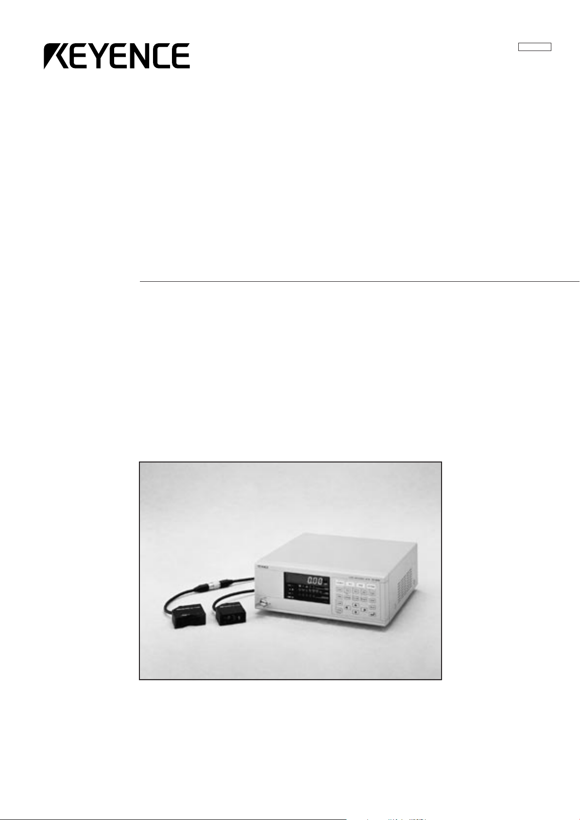
Ultra High Accuracy Laser Displacement Meter
96M1119
LC-2400 Series
Page 2
Safety Precautions
This manual describes how to install the LC-2400 Series as well as its
operating procedures and precautions. Please read this manual carefully to
get the best from your LC-2400 Series.
Symbols
General Precautions
The following symbols alert you to important messages. Be sure to read
these messages carefully.
WARNING
CAUTION
Note
• At startup and during operation, be sure to monitor the functions and
performance of the LC-2400 series.
• We recommend that you take substantial safety measures to avoid any
damage in the event a problem occurs.
• Do not open or modify the LC-2400 series or use it in any way other than
described in the specifications.
• When the LC-2400 series is used in combination with other instruments,
functions and performance may be degraded, depending on operating
conditions and the surrounding environment.
Failure to follow instructions may lead to injury.
(electric shock, burn, etc.)
Failure to follow instructions may lead to product
damage.
Provides additional information on proper operation.
CAUTION
• Do not use the LC-2400 series for the purpose of protecting the human
body.
Turn the power OFF when connecting or disconnecting the sensor
head connector, power supply cables, or any of the optional boards.
Otherwise, the laser diode or other electronic components may become degraded or damaged.
i
Page 3
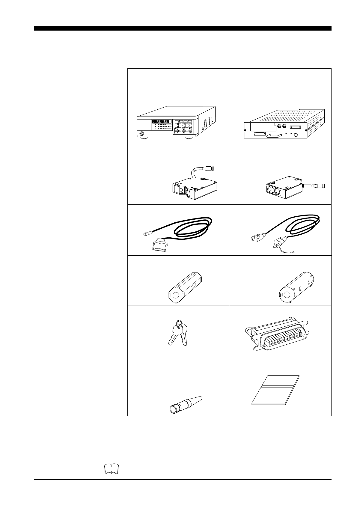
Contents of the Package
The LC-2400 series includes the following items. Check that none of the
items are missing or damaged.
● Display unit model:
LC-D1A/LC-D1W (Qty: 1)
If the control unit was ordered separately, the display unit is not included.
● Control unit model:
LC-C1A / LC-C1W/LC-C2(1)
If the display unit was ordered, the
control unit is incorporated in the display
unit.
● Sensor head
1.
Check that the requested sensor head is included in the contents.
model: LC-2420 model: LC-2440
LC-2430 LC-2450
● 3-m connecting cable (1)
1., 2.
● 2-m power cable (1)
Note
● Ferrite core
ESD-SR-25 (TOKIN) for RS-232C
cable (2)
3.
● Ferrite core
ZCAT3035-1330 (TDK) for CONTROL I/O cable (2)
3.
● Power supply key (2) ● 24-pin control I/O connector (1)
● 4-pin laser remote grounding
● Instruction manual (1)
plug (1)
Inserting this plug into the LASER
REMOTE connector on the rear panel
LC–2400 Series
enables laser emission. (See page 15.)
Instruction Manual
1. Depends on quantity ordered
2. 5-m or 10-m cable is also available.
(To use a 5-m or 10-m cable with the LC-2400 series that has been calibrated for
a 3-m cable the unit must be recalibrated by KEYENCE. We also offer the LC2400 series configured for 5-m and 10-m cables.)
3. Included with the LC-2400W series.
• The 5-m or 10-m cable is not available for the LC-2400W series.
• The LC-C1W cannot be used seperately from the display unit.
ii
Page 4
WARRANTIES AND DISCLAIMERS
Sea page 113.
Conventions The following symbols are used in this manual:
Failure to follow instructions may lead to injury.
WARNING
CAUTION
(electric shock, burn, etc.)
Cautions against procedures which may result in
malfunctions or measurement errors as well as
hazardous operating conditions. Be sure to read
this information carefully.
Turn to this page for more detailed information on
a given subject.
Note
Read here for more details or for reference information on a given subject. This information can be
read as required.
LC-2400 operation keys.
iii
Page 5
How to Use This
Instruction Manual
This instruction manual is composed of 9 chapters. An introduction to each
chapter is given below:
Users who are using the LC-2400 series for the first time are encouraged to
read through the entire instruction manual.
Chapter Guide
1. LASER SAFETY PRECAUTIONS
This chapter describes the safety precautions for
dealing with the laser in the LC-2400 series.
2. SYSTEM CONFIGURATION
This chapter introduces the LC-2400 series measurement system. A "Quick Reference Table" is also
included to help you quickly locate the information
and procedures that you require.
3. PART NAMES AND FUNCTIONS
This chapter identifies parts used in the LC-2400
series.
4. OPERATING INSTRUCTIONS
This chapter explains in detail how to operate the
LC controller. Please read and follow the instructions in this chapter carefully before operating the
LC.
5. CONNECTIONS
This chapter explains the procedures for installing
a sensor and connecting it to the LC controller.
6. SETTING UP
This chapter explains how to set the parameters
quickly and easily for obtaining accurate measurements with the LC-2400 series. Read how to set
the parameters in this chapter after checking the
system setup against the table given in Chapter 2-4
"Quick Reference Table".
7. MEASUREMENT PROCEDURE
This chapter explains measurement procedures
using various targets.
8. EXTERNAL I/O FUNCTIONS
This chapter explains how to communicate with
external I/O devices such as a personal computer.
9. APPENDIX
The appendix includes a troubleshooting guide, a
glossary, and a description of the expansion I/Os.
iv
Page 6

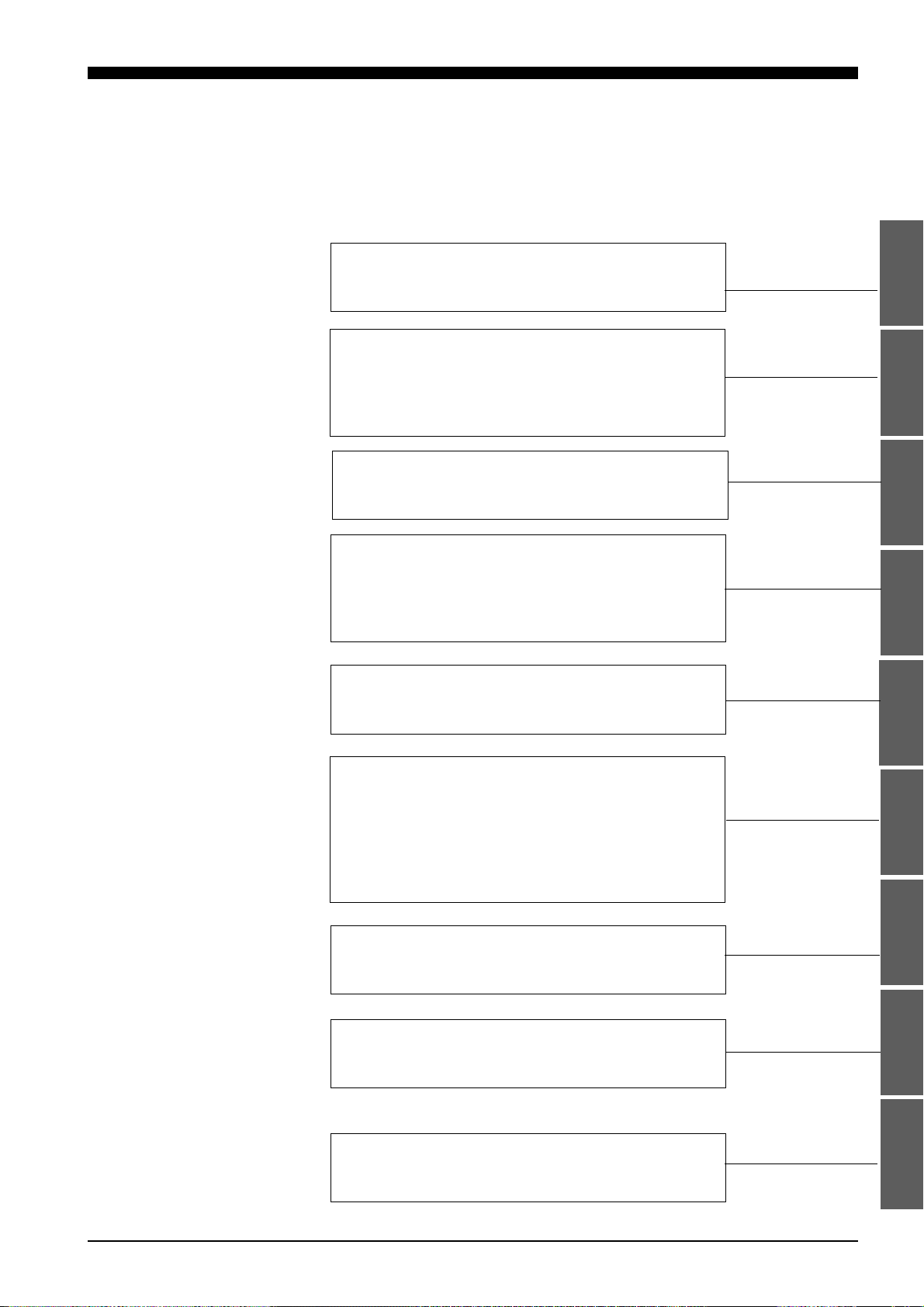
TABLE OF CONTENTS
CHAPTER 1 LASER SAFETY PRECAUTIONS 1
1-1 Classification...................................................................................2
1-2 Warning Label.................................................................................2
1-3 Label Location ................................................................................3
1-4 Safety Consideration ......................................................................3
1-5 Safety Features Provided with the LC-2400 Series........................4
CHAPTER 2 SYSTEM CONFIGURATION 5
2-1 Basic System Configuration............................................................6
2-2 Expansion System Configuration....................................................7
2-3 Sensor Head Types and Functions ................................................8
2-4 Quick Reference Table ...................................................................9
CHAPTER 3 PART NAMES AND FUNCTIONS 11
3-1 Controller ......................................................................................12
Front Panel ..............................................................................12
Rear Panel...............................................................................14
3-2 Sensor Head.................................................................................16
CHAPTER 4 OPERATING INSTRUCTIONS 17
4-1 Instructions for Using Controller and Sensor Head ......................18
After Receiving the LC-2400 Series ........................................18
Daily Maintenance Instructions................................................18
Replacing Battery ....................................................................19
Instructions for Sensor Setup ..................................................20
Hints on Correct Use ...............................................................10
CHAPTER 5 CONNECTIONS 21
5-1 Connecting Controller to Sensor Head .........................................22
5-2 Connecting Power Supply Cable ..................................................22
Connecting Controller to Sensor Head
When Using the Display Unit.................................................22
Connecting the Power Supply Unit
to a Separate Control Unit ....................................................23
5-3 Grounding Controller ....................................................................23
Grounding the Controller
When Using the Display Unit.................................................23
Grounding the Control Unit......................................................23
5-4 Installing LC-B3 Board (2CH Sensor Head Board).......................24
5-5 Installing GP-IB or DIGITAL I/O Board .........................................24
5-6 Adjusting Sensor Head Position ...................................................25
v
Page 7

CHAPTER 6 SETTING UP 27
6-1 Basic Operation of Controller........................................................28
6-2 Selecting Measurement Mode ......................................................30
6-3 Calibrating Sensitivity (Gain Selection).........................................30
6-4 Selecting the Display/Output Mode ..............................................31
6-5 Correcting Measurement Error (Calibration).................................32
6-6 Offset Values ................................................................................35
6-7 Reducing Variation in Measurement Data
(Setting Number of Averaging Measurements) ..........................36
6-8 Reducing the Effect of Target Surface Irregularities
(Setting Low-pass Filter Value)...................................................36
6-9 Setting Range for Light Intensity (INT. LIMIT) ..............................37
6-10 Setting Upper/Lower Limits for Measurements
(Setting Tolerance) .....................................................................39
6-11 Setting Number of Digits Displayed ..............................................40
6-12 Storing and Loading Settings (Programming)...............................41
CHAPTER 7 MEASUREMENT PROCEDURE 43
7-1 Measuring with One Sensor Head................................................44
7-2 Measuring with Two Sensor Heads ..............................................45
CHAPTER 8 EXTERNAL INPUT/OUTPUT 49
8-1 RS-232C Interface ........................................................................50
8-2 Control I/O (Standard Equipment on Display Unit) .......................71
8-3 Analog Voltage Output (Standard Equipment) .............................73
8-4 Digital I/O (Standard Equipment on Control Unit).........................74
CHAPTER 9 APPENDIX 79
9-1 Trouble-Shooting Guide................................................................80
9-2 Hints on Highly Accurate Measurement .......................................83
9-3 Specifications................................................................................84
9-4 Dimensions ...................................................................................85
9-5 Characteristics ..............................................................................87
9-6 Initial Setting List...........................................................................89
9-7 Glossary........................................................................................90
9-8 Expansion I/O (Optional) ..............................................................94
9-9 Index ...........................................................................................111
WARRANTIES AND DISCLAIMERS 113
vi
Page 8

CHAPTER 1
LASER SAFETY PRECAUTIONS
1-1 Classification ................................................................... 2
1-2 Warning Labels ................................................................ 2
1-3 Label Location ................................................................. 3
1-4 Safety Consideration ....................................................... 3
1-5 Safety Features Provided with the LC-2400 Series ......... 4
Page 9
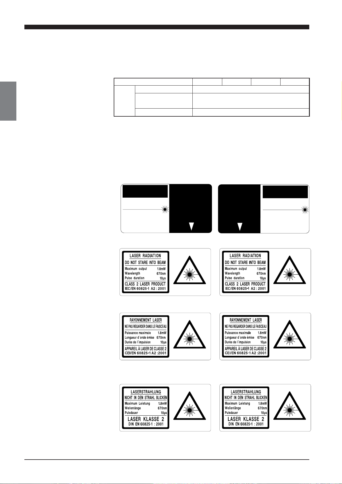
1-1 Classification
AVOID EXPOSURE
LASER RADIATION
IS EMITTED FROM
THIS APERTURE.
1-2 Warning Labels
1-1 Classification
1-2 Warning Labels
The LC-2400 series employs a visible semiconductor laser as its light source
classified as follows:
Model LC-2420 LC-2430 LC-2440 LC-2450
Class FDA (CDRH) Class II
IEC/EN 60825-1:1993+
A2: 2001
DIN EN 60825-1 2001 Klasse 2
Class 2
Warning Labels
1) Warning labels
FDA Class II
CAUTION
LASER RADIATIONDO NOT STARE INTO BEAM
SEMICONDUCTOR LASER 670nm
MAXIMUM OUTPUT 1.9mW
(AVERAGE OUT PUT 950µW)
PULSE DURATION 10µSEC
CLASS II LASER PRODUCT
IEC Class 2
IEC (French) Classe 2
AVOID EXPOSURE
LASER RADIATION
IS EMITTED FROM
THIS APERTURE.
AVOID EXPOSURE
LASER RADIATION
IS EMITTED FROM
THIS APERTURE.
AVOID EXPOSURE
LASER RADIATION
IS EMITTED FROM
THIS APERTURE.
CAUTION
LASER RADIATIONDO NOT STARE INTO BEAM
SEMICONDUCTOR LASER 670nm
MAXIMUM OUTPUT 1.9mW
(AVERAGE OUT PUT 950µW)
PULSE DURATION 10µSEC
CLASS II LASER PRODUCT
2
DIN
Klasse 2
CHAPTER 1 Laser Safety Precautions
Page 10
1-3 Label Location
LASER RADIATION
IS EMITTED FROM
THIS APERTURE.
CAUTION
CAUTION
LASER RADIATION
IS EMITTED FROM
THIS APERTURE.
CAUTION
LASER RADIATION
IS EMITTED FROM
THIS APERTURE.
LASER RADIATION
IS EMITTED FROM
THIS APERTURE.
CAUTION
FDA
• LC–2420/2430
1-3 Label Locations
1-4 Safety Consideration
FDA Warning labels are attached to the sensor head as shown below. The
IEC/DIN Warning labels are packaged with the LC-2400 Series. Affix the
Warning labels on the sensor head as shown below.
• LC–2440/2450
CAUTION
LASER RADIATIONDO NOT STARE INTO BEAM
SEMICONDUCTOR LASER 670nm
MAXIMUM OUTPUT 1.9mW
(AVERAGE OUT PUT 950µW)
PULSE DURATION 10µSEC
CLASS II LASER PRODUCT
IEC/DIN
• LC–2420/2430
LC–2420 LC–2420
AVOID EXPOSURE
LASER RADIATION
IS EMITTED FROM
THIS APERTURE.
AVOID EXPOSURE
LASER RADIATION
IS EMITTED FROM
THIS APERTURE.
CAUTION
LASER RADIATIONDO NOT STARE INTO BEAM
SEMICONDUCTOR LASER 670nm
MAXIMUM OUTPUT 1.9mW
(AVERAGE OUT PUT 950µW)
PULSE DURATION 10µSEC
CLASS II LASER PRODUCT
CAOTION-LASER RADIATION WHEN OPEN
DO NOT STARE INTO BEAM
Aperture Aperture
LC–2420 LC–2420
Aperture Aperture
CAUTION
LASER RADIATIONDO NOT STARE INTO BEAM
SEMICONDUCTOR LASER 670nm
MAXIMUM OUTPUT 1.9mW
(AVERAGE OUT PUT 950µW)
PULSE DURATION 10µSEC
CLASS II LASER PRODUCT
AVOID EXPOSURE
LASER RADIATION
IS EMITTED FROM
THIS APERTURE.
• LC–2440/2450
AVOID EXPOSURE
LASER RADIATION
IS EMITTED FROM
THIS APERTURE.
LC–2440LC–2440
CAUTION
LASER RADIATIONDO NOT STARE INTO BEAM
SEMICONDUCTOR LASER 670nm
MAXIMUM OUTPUT 1.9mW
(AVERAGE OUT PUT 950µW)
PULSE DURATION 10µSEC
CLASS II LASER PRODUCT
CAOTION-LASER RADIATION WHEN OPEN
DO NOT STARE INTO BEAM
LC–2440LC–2440
1-4 Safety Consideration
Use of controls or adjustments or the performance of procedures other than
those specified herein may result in hazardous radiation exposure.
The laser beam is not harmful to the skin. There is, therefore, no danger in
exposing arms or hands to the beam. The only possible health hazard is in
exposing the eyes to the laser beam. Damage to the eyes can occur if the
operator stares directly into the beam.
Follow the safety precautions below to ensure operator safety:
• Operate the LC-2400 series only according to the procedures described in this instruction manual.
Otherwise, injury may occur due to expose to the laser beam.
• Do not disassemble the sensor head.
Laser emission from the LC-2400 series is not automatically stopped if
the sensor head is disassembled. If you disassemble the sensor head
for inspection or repair, you may be exposed to the laser beam. If the
LC-2400 series malfunctions, contact KEYENCE immediately.
• Do not look directly at the laser beam.
Looking directly at the laser beam may result in serious eye injury.
CAUTION
WARNING
CHAPTER 1 Laser Safety Precautions
3
Page 11
1-5 Safety Features Provided with the LC-2400 Series
• Diffuse-reflective sensor head
(LC-2440/LC-2450)
• Regular-reflective sensor head
(LC-2420/LC-2430)
Open
Close
Open
Close
• Protective enclosure
We recommend that you install a protective enclosure around the sensor
head to prevent any person from getting near the sensor head during
operation.
• Protective goggles
We recommend that you wear protective goggles when using the LC2400 series.
Note
The intense light from this laser can be harmful to the eyes during prolonged
viewing. Normal reflex blinking is usually enough to prevent any eye damage. However, it is best to wear laser protective glasses whenever working
around a sensor head.
1-5 Safety Features Provided with the LC-2400 Series
The LC-2400 series comes with the following safety features:
■ Laser ON alarm LED
Both the sensor head and the controller panel have a visible LED that lights
when laser is ready to be and is being emitted.
Note
LEDs can be checked to see if they are lit even when you are wearing laser
protective glasses.
Reference: Laser ON alarm LED (p.12, 14, 16)
■ Delay of laser beam emission
To prevent an operator from being exposed to the laser beam, the laser
beam is emitted three seconds after the laser ON alarm LED lights.
■ Laser emission remote control input connector
The laser emission control connector is located on the rear panel of the
control unit. The laser can be turned on or off by a remote control signal
through this connector.
Reference: Laser Remote Grounding Connector (p.15)
4
■ Key-operated power switch
The controller power switch can be locked using the attached key.
When the LC-2400 controller is OFF, the key can be removed.
■ Laser beam shield
The sensor head transmitter comes with a laser beam shield.
Precautions for parameter setup and measurements
If there is a danger of an operator looking into the laser beam when working
in front of the sensor head, close the laser beam shield as shown below
before starting operations.
Close or open the laser beam shield as shown below:
CHAPTER 1 Laser Safety Precautions
Page 12

CHAPTER 2
SYSTEM CONFIGURATION
2-1 Basic System Configuration ............................................ 6
2-2 Expansion System Configuration .................................... 7
2-3 Sensor Head Types and Functions ................................. 8
2-4 Quick Reference Table.................................................... 9
Page 13
2-1 Basic System Configuration
The LC-2400 series is equipped with I/O ports for connecting to external
equipment and a slot for installing an optional expansion board. By connecting personal computers or other devices to the LC-2400 series, measurement data obtained with the LC-2400 series can be used for various applications.
2-1 Basic System Configuration
The LC controller consists of a display unit and control unit. If required, the
control unit can be used separately from the display unit. There are also two
expansion slots; one for the optional LC-B3 board which, when installed,
allows the use of a second sensor head and a second slot for either a
DIGITAL I/O board or GP-IB board.
However, the LC-2400W series does not incorporate these expansion slots.
Display unit
(model: LC-D1A/LC-D1W)
Control unit
(model: LC-C1A/LC-C1W/LC-C2)
Expansion slot for
DIGITAL I/O board* (model: LC-B1)
or GP-IB board*(model: LC-B2)
1., *2.
CHAPTER 2 System Configuration
6
Expansion slot for
LC-B3 2CH sensor
head board*
1., *2.
1CH sensor head port: for
LC-2420/LC-2430/LC-2440/LC-2450
*1. Optionally available from KEYENCE
*2. Cannot be used with the LC-2400W series.
Page 14
2-2 Expansion System Configuration
For flexible expansion, a variety of external equipment can be connected to
the LC-2400 series, as shown below.
2-2 Expansion System Configuration
Connect a PLC ,
photoelectric sensor ,
or proximity sensor .
This port is used to
switch memory banks,
input auto-zero and
hold signals, and output
alarm signals.
With a commercially available
printer connected, you can record
measurement results.
*1.
*1.
*1.
2ch sensor
head port
1ch sensor
head port
Control
I/O port
With the optionally available
2CH board (model: LC-B3),
you can connect the second
sensor head (model: LC-2420
/-2430/-2440/-2450) to the
controller.
Connect the first sensor
head (model: LC-2420
/-2430/-2440/-2450).
*1., *2.
RS-232C port
With the DIGITAL I/O board
(model: LC-B1) or GP-IBboard
(model: LC-B2), you can send
data to and receive it from
a personal computer.
You can send data to and receive
it from a personal computer through
one of the interface (RS-232C,
DIGITAL I/O , GP-IB ).
*1. *1.
Expansion slot
Analog voltage output
*1., *2.
*1., *2.
With an oscilloscope
or pen recorder
connected, you can
monitor changes
in light intensity and
target displacement
through analog
voltage signals.
*1. Optionally available from KEYENCE
*2. Cannot be used with the LC-2400W series.
CHAPTER 2 System Configuration
7
Page 15
2-3 Sensor Head Types and Functions
2-3 Sensor Head Types and Functions
The LC-2400 Series gives you a choice of 4 sensor head models.
LC-2420/LC-2430: Regular-reflective sensor heads
Regular-reflective sensor heads are used to measure targets having a highly
reflective or mirror-like surface.
LC-2440/LC-2450: Diffuse-reflective sensor heads
Diffuse-reflective sensor heads are used to measure targets having a lowreflective or opaque surface.
CHAPTER 2 System Configuration
8
Page 16
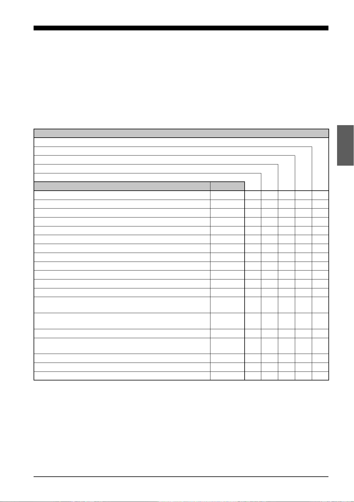
2-4 Quick Reference Table
2-4 Quick Reference Table
Sensor setup, cable connections, and various parameters must be set
before starting measurement. However, some of the parameters are not
necessary, depending on system configuration and the type of measurements being done. The following table shows the procedures to follow, in
sequential order, before starting measurement. Find the items pertaining to
your setup in the table to determine which sections of the manual are required reading.
Type of measurement
Trial measurement
Measuring height
Measuring eccentricity
Measuring thickness
Measuring difference in height
Section No. Page No.
5-1 Connecting Controller to Sensor Head p.22 R R R R R
5-2 Connecting Power Supply Cable p.22 R R R R R
5-3 Grounding Controller p.23 R R R R R
5-4 Installing LC-B3 Board (2CH Sensor Head Board) p.24 R R
5-5 Installing GP-IB or DIGITAL I/O Board p.24
5-6 Adjusting Sensor Head Position p.25 R R R R R
6-1 Basic Operation of Controller p.28 R R R R
6-2 Selecting Measurement Mode p.30 R R R R R
6-3 Calibrating Sensitivity (Gain Selection) p.30 R R R R
6-4 Selecting the Display/Output Mode p.31 R R
6-5 Correcting Measurement Error (Calibration) p.32 R R R R
6-6 Offset Values p.35 O O O O
6-7 Reducing Variation in Measurement Data
(Setting Number of Averaging Measurements)
6-8 Reducing the Effect of Target Surface Irregularities
(Setting Low-pass Filter Value)
6-9 Setting Range for Light Intensity (INT. LIMIT) p.37 O O O O
6-10 Setting Upper/Lower Limits for Measurements
(Setting Tolerance)
6-12 Storing and Loading Settings (Programming) p.41 R R R R
7-1 Measuring with One Sensor Head p.44 R R
7-2 Measuring with Two Sensor Heads p.45 R R
p.36 R R R R
p.36 O O O O
p.39 O O O O
R: Required reading
O: Optional reading
CHAPTER 2 System Configuration
9
Page 17

CHAPTER 2 System Configuration
10
Page 18

CHAPTER 3
PART NAMES AND FUNCTIONS
3-1 Controller ....................................................................... 12
3-2 Sensor Head.................................................................. 16
Page 19
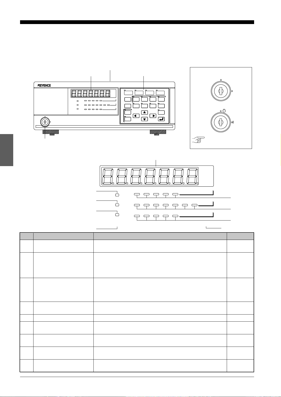
3-1 Controller
mm
µ m
1
6
mm
µ m
3-1 Controller
Front Panel
OFF
POWER
Key-operated power switch
Display
ON
HIGH
GO
LOW
LASER ON
Display
AUTO 1 2 3 4
INT.
LIMIT OFFSET CAL
LIMIT
12345
9
8
7
Display unit
ANALOG
BAUD
DIGIT
RATIO
RATE
PROGRAM
LOCK
HIGH
GO
LOW
LASER ON
Operation keys
LASER DISPLACEMENT METER
NORMAL P–P
1CH 2CH
GAIN
GAIN
PRM
PRM
LOAD
SAVE
PROGRAM
2–HEAD
AVERAGE
FILTER
PEAK
ADD SUB
INTENSITY
LC-2400A
BOTTOM
ZERO
HOLD
LC-2400A
OFF
ON
POWER
LC-2400W
STAND-BY
ON
POWER
Reference: Refer to P.44.
AUTO 1 2 3 4
ANALOG
LIMIT OFFSET CAL
12345
INT.
LIMIT
RATIO
BAUD
RATE
DIGIT
PROGRAM
GAIN
2
PRM
3
4
LOCK
5
No. Name Function Ref. page
1 Display panel Displays measured values, preset values and error mes-
sages.
p.82
2 GAIN LEDs Indicates the receiver sensitivity. One of the four LEDs
corresponding to the current sensitivity will be lit.
When the receiver sensitivity is set to AUTO, one of the four
p.30
LEDs and the AUTO LED will be lit.
3 PARAMETER LEDs Lights when setting parameters such as upper/lower toler-
ance limits, offset, calibration, intensity limit, analog ratio,
baud rate and display digit. The LED corresponding to the
p.28
parameter currently being changed lights.
4 PROGRAM LEDs The LED corresponding to the selected program number will
be lit. The LEDs blink during program selection.
5 PANEL LOCK LED Lights when the operation keys are disabled.
6 Laser ON alarm LED Lights when the laser beam is ready to be and is being
emitted from the sensor head.
7 LOW LED Lights when a measured value falls below the preset lower
limit in each measurement mode.
8 GO LED Lights when a measured value is within the preset tolerance
range of that measurement mode.
9 HIGH LED Lights when a measured value exceeds the preset upper limit
of that measurement mode.
p.41
p.55
p.4., 26
p.39
p.39
p.39
CHAPTER 3 Part Names and Functions
12
Page 20
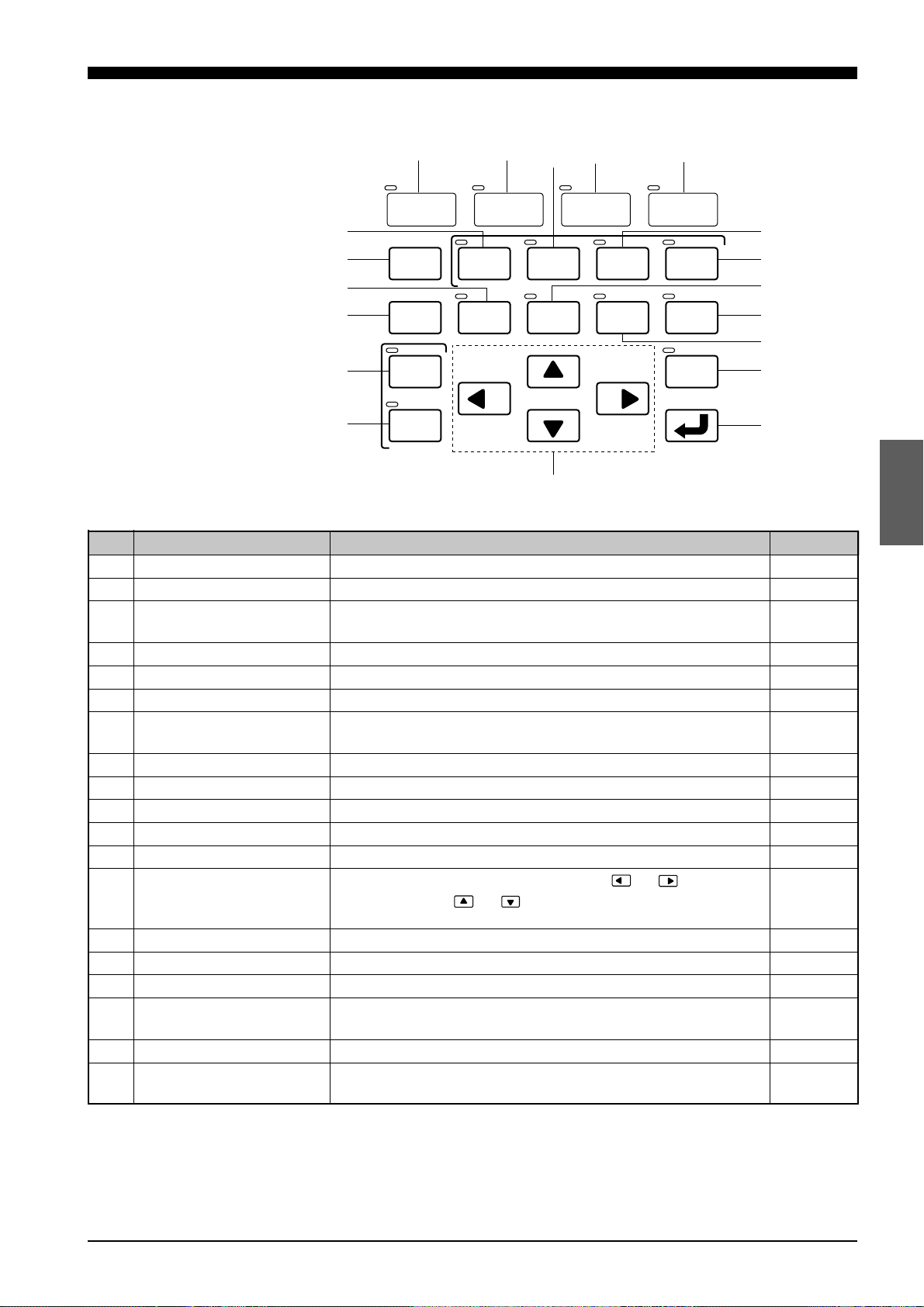
Operation Keys
3-1 Controller
p.
P
O
N
R
Q
M
0
NORMAL P–P
GAIN
PRM
LOAD
SAVE
PROGRAM
A
1CH 2CH
2–HEAD
AVERAGE
B
FILTER
L
C
PEAK
ADD SUB
INTENSITY
D
BOTTOM
ZERO
HOLD
E
F
G
H
I
J
K
No. Name Function Ref. page
0 NORMAL key Press this key to measure targets in the NORMAL mode. p.30
A P-P key Press this key to measure targets in the Peak-to-Peak mode. p.30
B 2CH key Press this key to measure targets with the second sensor
head (2CH slot) when two sensor heads are connected.
p.31, 45
C PEAK key Press this key to measure target in the PEAK mode. p.30
D BOTTOM key Press this key to measure target in the BOTTOM mode. p.30
E ADD key Press this key to measure thickness using two sensor heads. p.31, 46
F SUB key Press this key to measure height deviation using two sensor
heads.
p.31, 47
G FILTER key Press this key to set a (Low-pass) FILTER value. p.36
H ZERO key Press this key to reset a measured value to "0". p.29
I INTENSITY key Press this key to display received laser beam intensity. p.29
J HOLD key Press this key to hold a measured value. p.29
K ENTER key. Press this key to enter the value you set. p.28
L Numeral change keys Press this key to change values. Press or to shift
digits and press or to increase or decrease values as
p.28
well as change signs.
M SAVE key Press this key to save a measured value. p.41
N LOAD key Press this key to load stored parameter settings. p.41
O PRM key Press this key to change parameter settings. p.28
P AVERAGE key Press this key to set the number of averaging measure-
ments.
p.36
Q GAIN key Press this key to change receiver sensitivity. p.30
R 1CH key Press this key to use the first sensor head (1CH port) when
two sensor heads are connected.
p.31,44
CHAPTER 3 Part Names and Functions
13
Page 21

3-1 Controller
Rear Panel
a
Display unit
Control unit
S
CONTROL I/O
HEAD No.
INTENSITY
RS-232C
`
T
U
MONITOR
DISPLACEMENT
BATTERY LASER ON LASER
LC–C1
]
HEAD No.
\
V
W
REMOTE
[
Z
X
100~240V AC
FUSE 3.15A
Y
POWER
ON
OFF
No. Name Function Ref. page
S CONTROL I/O port Inputs signals (program, hold on/off, auto-zero on/off, etc.)
from and outputs signals to external equipment.
T INTENSITY output connector Outputs the laser beam intensity measured with the LC in
analog voltage.
U DISPLACEMENT output Outputs the measured displacement value as an analog
connector voltage.
p.71
p.74
p.73
V Expansion I/O slot Install GP-IB board* or digital I/O board* in this slot. p.24, 95
W 1CH sensor head connector Connect the 1CH sensor head to this connector. p.22
X Ventilating fan Radiates heat from the controller. p.16
Y Power supply connector Connect the power supply cable to this connector. p.22
Z F.G. terminal Ground the controller through this terminal. p.23
[ LASER REMOTE connector The LASER REMOTE connector is used to control laser
emission by an external input signal. When this connector
is not used, be sure to connect the attached laser remote
p.11
grounding plug to this connector.
\ Laser ON alarm LED Lights when a laser beam is ready to be and is being
emitted from the sensor head.
p.18, 26
] BATTERY LED Lights when the internal backup battery is exhausted. p.15
^ RS-232C I/O port Connect a personal computer or other device to this port
to externally control the LC.
p.50
a LC-B3 board slot Install the optional LC-B3 board in this slot. p.24
The LC-B3 cannot be used with the LC-2400W series.
b Power switch Use this switch to turn the main power supply on or off.
(LC-2400W only)
b
* Optionally available
CHAPTER 3 Part Names and Functions
14
Page 22
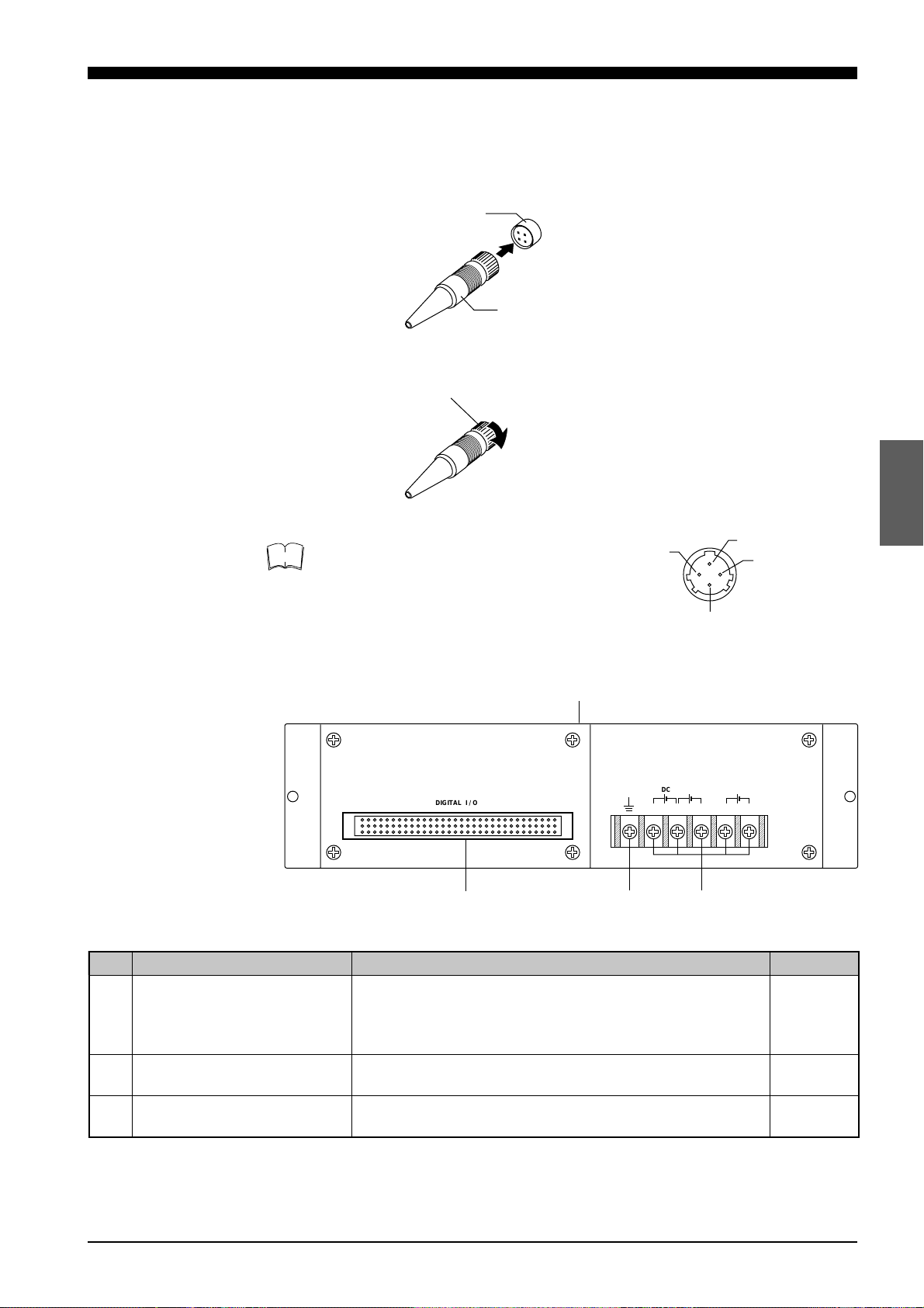
3-1 Controller
DIGITAL I / O
DC DC DC
+15V –15V +5V0V 0V
d
c
b
Control unit
Laser Remote Grounding
Plug
Note
Follow the instructions below to insert this plug into the LASER REMOTE
connector.
1. Check the connector’s orientation before insertion.
LASER REMOTE
connector
Laser remote
grounding plug
2. Turn the stopper clockwise to lock it in place.
Stopper
Laser emission is enabled when pins 1 and 2
of the connector are shorted.
4
1
2
3
Control Unit Face
No. Name Function Ref. page
b 96-pin DIGITAL I/O port The control unit is connected to the display unit via this
connector. Digital signals are output through this connector when the control unit is used separately from the
display unit.
c Earth ground terminal Ground the control unit through this terminal when using
the control unit separately from the display unit.
d Power supply terminals Connect the power supply cable to these terminals when
using the control unit separately from the display unit.
p.74
p.23
p.23
CHAPTER 3 Part Names and Functions
15
Page 23
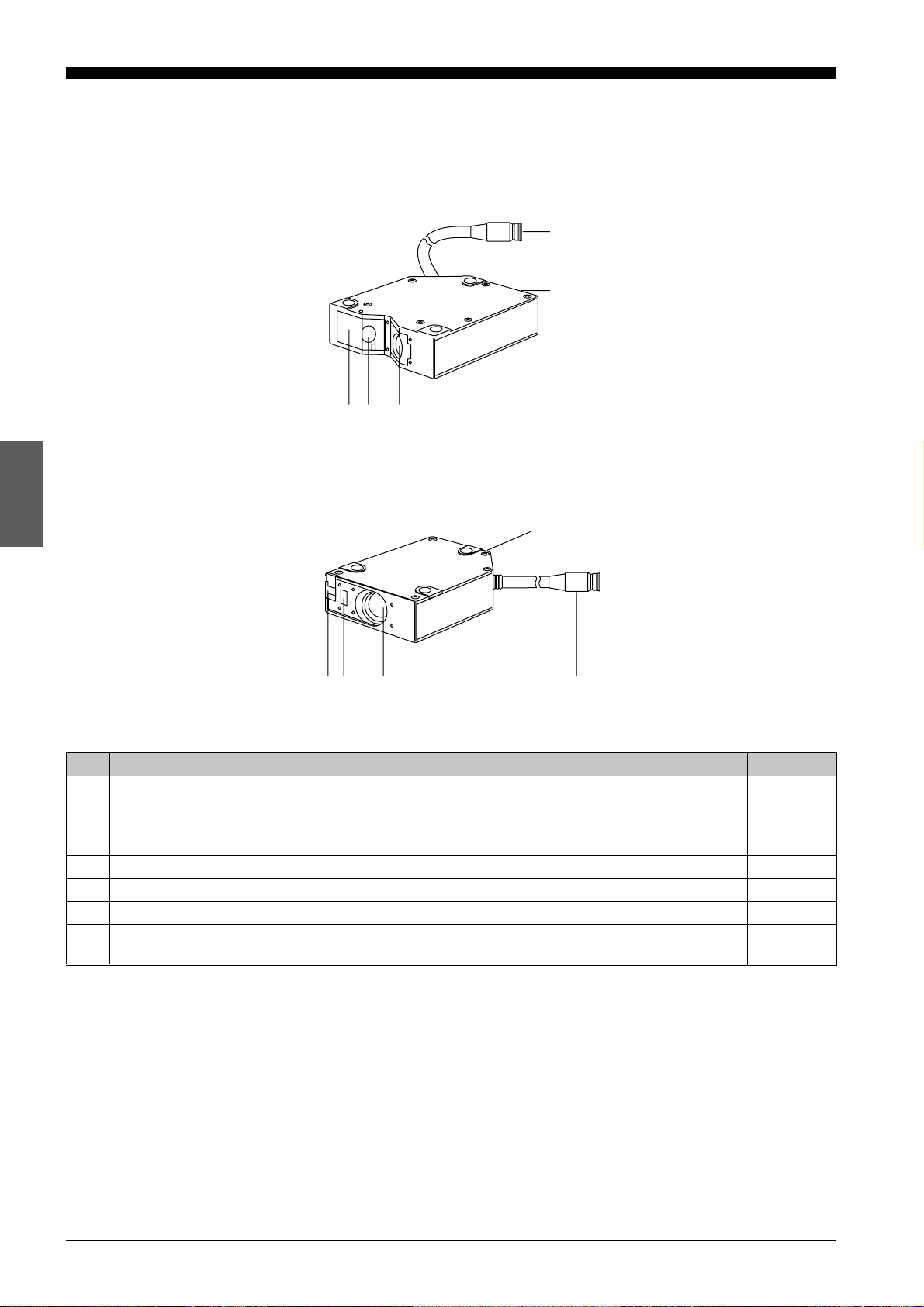
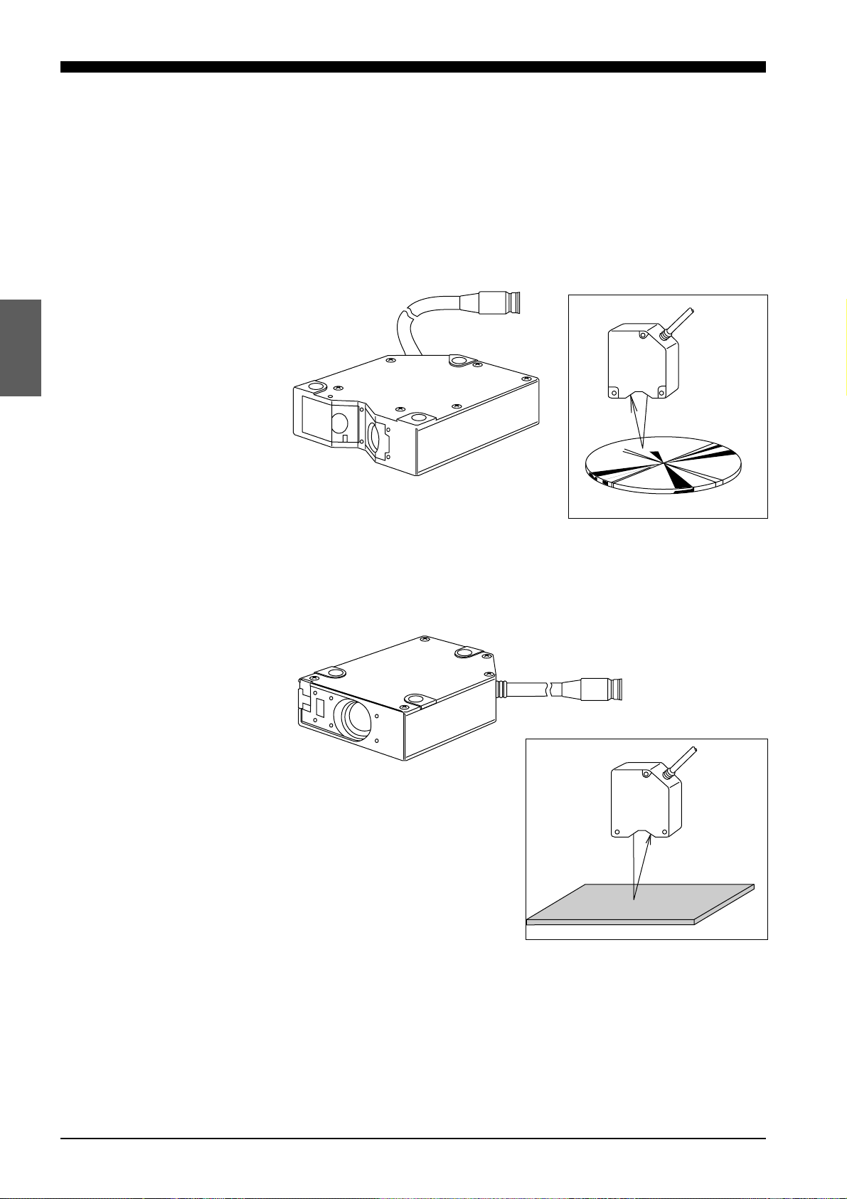
3-2 Sensor Head
3-2 Sensor Head
LC-2420/2430 (Regular-reflective)
h
i
ef g
LC-2440/2450 (Diffuse-reflective)
i
feg
No. Name Function Ref. page
e Laser beam shield The laser beam shield is used to cover the laser beam
transmitter. When operators are working near the sensor
head, if there is a risk of looking directly at the laser beam,
be sure to cover the transmitter with the shield.
f Transmitter Emits laser beams. p.18
g Receiver Receives the reflected laser beam. p.18
h Cable connector Connects the sensor head cable to the controller. p.22
i Laser ON alarm LED Lights when a laser beam is ready to be and is being
emitted from the sensor head.
h
p.4
p.4, 26
CHAPTER 3 Part Names and Functions
16
Page 24

CHAPTER 4
OPERATING INSTRUCTIONS
4-1 Instructions for Using Controller and Sensor Head............. 18
Page 25
4-1 Instructions for Using Controller and Sensor Head
Before operating the LC-2400 series, read the following instructions carefully. If you encounter any problems, please contact us.
4-1 Instructions for Using Controller and Sensor Head
After Receiving the
LC-2400 Series
Daily Maintenance
Instructions
• After receiving the LC, check the contents to see if any items were damaged during transportation.
• Check that all the items were included.
Reference: Contents of the Package (p.ii)
• Before using the LC, be sure to read this instruction manual for details on
the correct use of this product.
• Do not try to disassemble the LC or use a disassembled unit. Do not
disassemble the sensor head in particular, since all of the sensor head
parts have been factory-calibrated.
• Please handle the controller and sensor head with care. The precision
optical components in the sensor head are especially susceptible to
shock.
• The receiver and transmitter lenses are the critical components for
accurate measurement. Any flaw or dust on the lenses may result in
measurement errors. If dust has accumulated on the transmitter and
receiver lenses, clean the lens surface by following the procedures given
below.
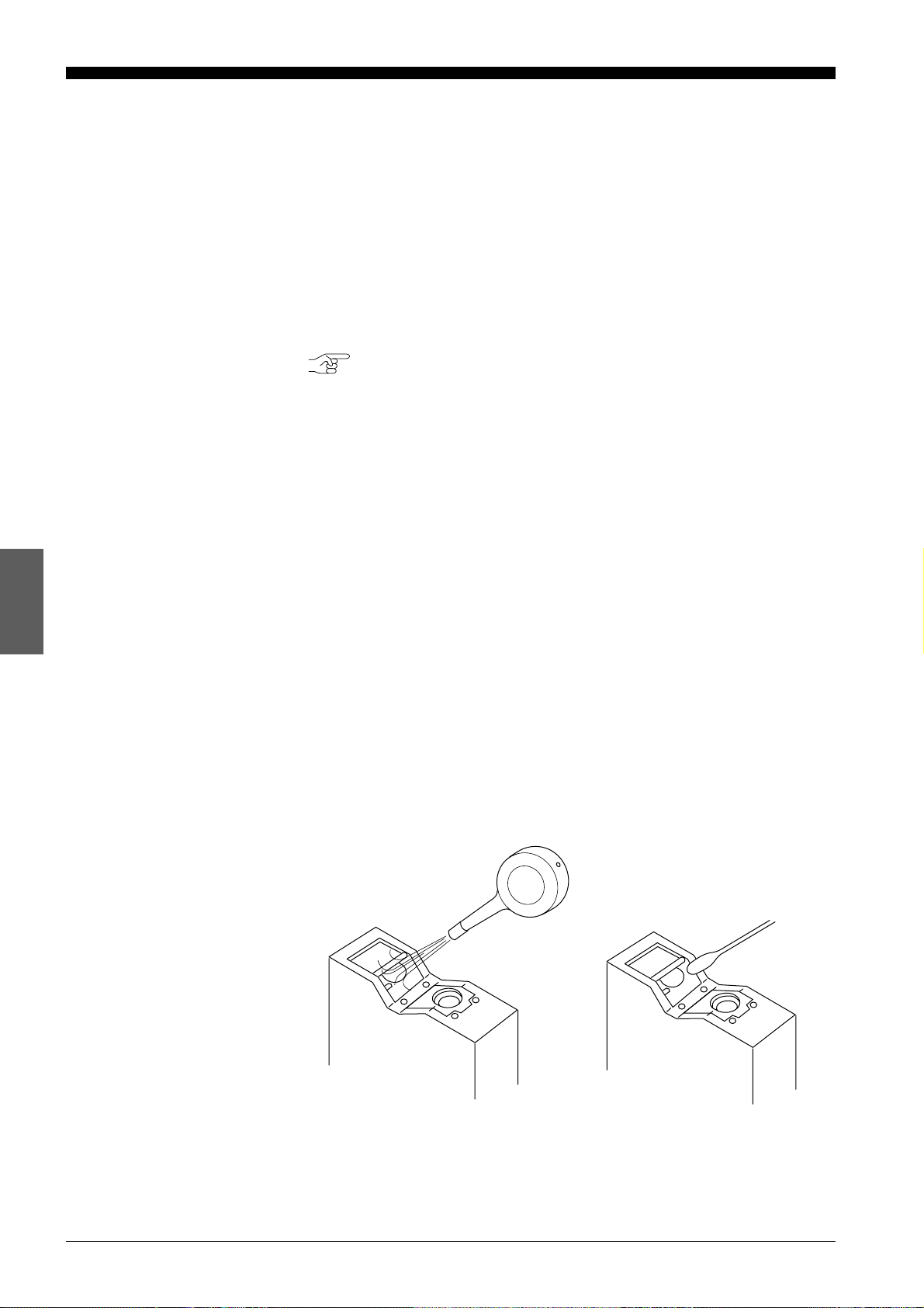
1. Blow the dust off the receiver and transmitter lenses using a manual
blower.
2. If dust persists, wipe the lens surface gently using a cotton swab dipped
in alcohol.
CHAPTER 4 Operating Instructions
18
Page 26
4-1 Instructions for Using Controller and Sensor Head
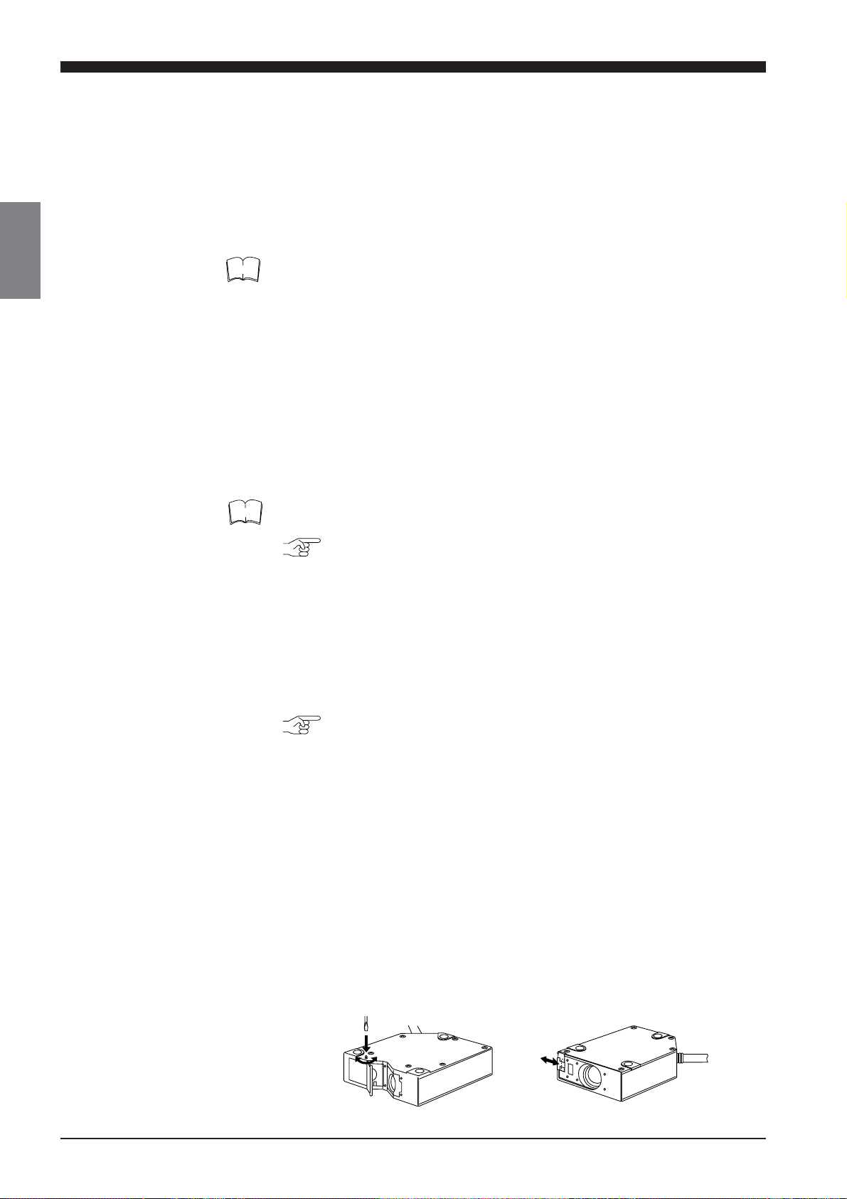
Replacing Battery
WARNING
CAUTION
The LC controller has an internal backup battery for storing parameter
settings. The expected battery life is 1 to 2.5 years. When the battery is
exhausted, the BATTERY LED lights. When this LED is lit, replace the
battery by following the procedure given below.
Danger of explosion if battery is incorrectly replaced. Replace only with the
same or equivalent type recommended by the manufacturer. Dispose of
used batteries according to the manufacturer's instructions.
Turn the power OFF and unplug the power cable from the wall outlet.
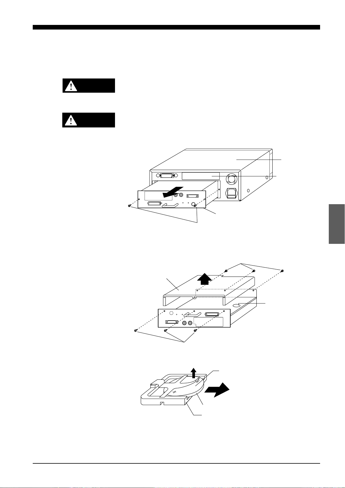
1. Remove the two screws from the back of the display unit and remove the
control unit.
Upper cover
Expansion slot
Control unit
Screws
2. Turn the control unit upside down, remove the six cover screws from the
cover and then remove the cover.
Locate the battery holder in the control unit.
Screws
Cover
Battery holder
Screws
3. Remove the battery from the battery holder.
Positive side
Flat lithium battery: CR2032
Internal backup battery
Battery holder
4. Install the new battery in the battery holder with the positive side facing
up. When installing a new battery, be sure that the polarity of the battery is
correct.
CHAPTER 4 Operating Instructions
19
Page 27
4-1 Instructions for Using Controller and Sensor Head
5. Put the cover back on the control unit and secure it with the six cover
screws.
6. Reinsert the control unit into the display unit with the top of the control unit
facing up, and secure the control unit with the two retaining screws.
Instructions for Sensor
Setup
CAUTION
Turn the power OFF when connecting or disconnecting the sensor
head connector, power supply cables, or any of the optional boards.
Otherwise, the laser diode or other electronic components may become degraded or damaged.
• Place the LC in a location that meets the following requirements:
Temperature: 0 to 40°C
Humidity: 35 to 85% RH (No condensation)
Placing the LC in a location that does not meet these requirements may
cause the controller and sensor head to malfunction.
Do not operate the LC in a location where extreme temperature variations
are expected.
• Do not operate the LC where volatile flammable objects or corrosive
gases are present.
• Do not expose the LC to extremely high humidity or water splashes.
• When using the control unit separately from the display unit, be sure to
provide a protective cover for the control unit during operation.
• To prevent noise, keep the connection cables separate from the power
cables. If this is not possible, shield or ground the connection cables.
Hints on Correct Use
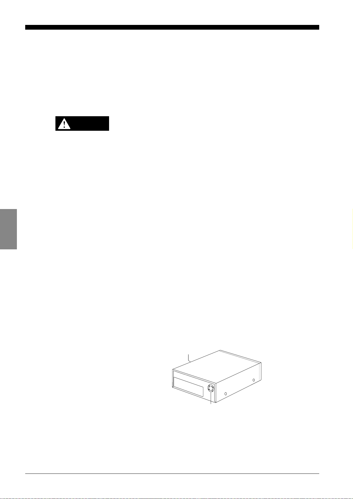
• Insulate the sensor head if noise is transferred through the sensor head.
• Do not block the ventilation port or the ventilation fan of the controller. If
they are blocked, the controller may overheat, resulting in a malfunction.
Note also that a ventilation fan is not provided with the control unit. When
using the control unit separately from the display unit, make sure that the
room is sufficiently ventilated.
Ventilation port
Ventilation fan
• Keep the ambient temperature at a constant level during measurement.
• If the sensor head is operating in a location where there is thick fog or hot
air, measurement errors may result.
• Be sure to leave the power on for at least 60 minutes before starting
measurements.
CHAPTER 4 Operating Instructions
20
Page 28

CHAPTER 5
CONNECTIONS
5-1 Connecting Controller to Sensor Head.......................... 22
5-2 Connecting Power Supply Cable................................... 22
5-3 Grounding Controller ..................................................... 23
5-4 Installing LC-B3 Board (2CH Sensor Head Board) ....... 24
5-5 Installing GP-IB or DIGITAL I/O Board .......................... 24
5-6 Adjusting Sensor Head Position .................................... 25
Page 29
5-1 Connecting Controller to Sensor Head
5-2 Connecting Power Supply Cable
5-1 Connecting Controller to Sensor Head
The 2CH sensor head cannot be used with the LC-2400W series.
CAUTION
Turn the power OFF when connecting or disconnecting the sensor
head connector, power supply cables, or any of the optional boards.
Otherwise, the laser diode or other electronic components may become degraded or damaged.
Connect the controller to the sensor head using the supplied connecting
cable. At this time, make sure that the control unit and sensor head have the
same serial number.
Options
Connecting cable
Sensor heads
2CH sensor head 1CH sensor head
If you purchase the LC-B3 and sensor head later, you can connect them to
the controller without adjustment because the sensor head and the LC-B3
have been factory-calibrated as a pair.
5-2 Connecting Power Supply Cable
Connecting the Power
Supply Cable When
Using the Display Unit
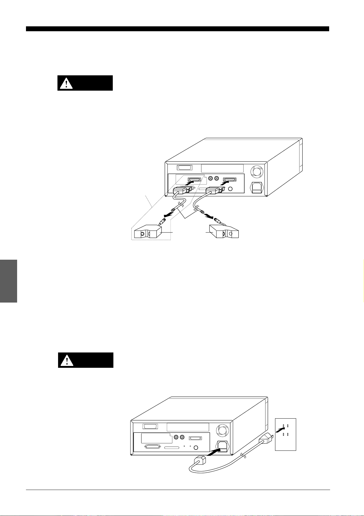
Turn OFF the LC controller before starting the following procedure.
CAUTION
Plug the power supply cable into the power supply socket located on the
rear of the display unit, and then into a wall outlet.
Power must be 100 to 240 VAC (50/60 Hz).
CHAPTER 5 Connections
22
Page 30
Connecting the Power
;
Supply Unit to a
Separate Control Unit
5-2 Connecting Power Supply Cable
5-3 Grounding Controller
Cannot be used with the LC-2400W series.
CAUTION
CAUTION
Turn OFF the power supply unit before starting the following procedure.
Connect the power supply unit to the power
supply terminals located on the front of the
control unit.
Note that the control unit uses the following types of power:
• ±15 VDC (±3%), 0.5A
• ±5 VDC (±5%), 3A, ripple (p-p): 100 mV max.
Be sure to supply
Supplying only +5 VDC may cause a malfunction.
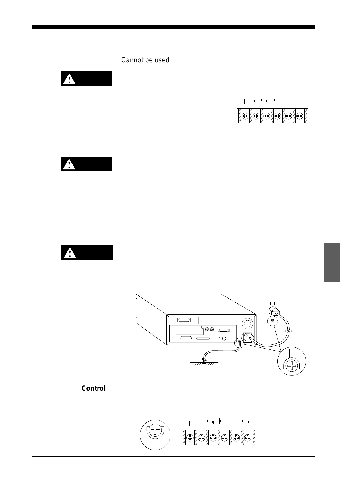
5-3 Grounding Controller
The controller can be grounded either by connecting the earth ground
terminal located on the rear of the display unit to a grounding electrode or by
connecting the ground wire of the power supply cable to the ground screw of
a wall outlet. To prevent any risk of malfunction, ground the LC both ways as
shown below.
DC DC DC
+15V –15V +5V0V 0V
±15 VDC and +5 VDC at the same time.
CAUTION
Grounding the
Controller When Using
the Display Unit
Grounding the Control
Unit
Be sure to ground the controller separately from other devices.
Earth-ground the controller through the earth ground terminal located on the
rear of the display unit with the ground wire of the power supply cable.
Cannot be used with the LC-2400W series.
Earth-ground the control unit through the earth ground terminal located on
the front of this unit.
DC DC DC
+15V –15V +5V0V 0V
CHAPTER 5 Connections
23
Page 31

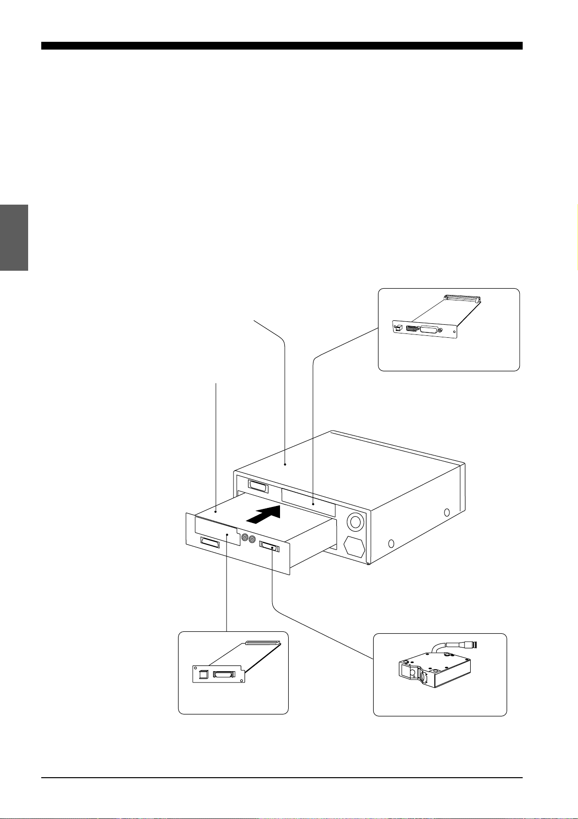
5-4 Installing LC-B3 Board (2CH Sensor Head Board)
5-5 Installing GP-IB or Digital I/O Board
5-4 Installing LC-B3 Board (2CH Sensor Head Board)
Cannot be used with the LC-2400W series.
To use two sensor heads with the LC controller, the LC-B3 board must be
inserted into the LC-B3 board slot located at the rear of the control unit. (The
LC-B3 board is optional. Contact KEYENCE for details.)
CAUTION
Turn OFF the LC and unplug the power cable from the wall outlet
before starting the following procedure.
1. Remove the two screws securing the LC-B3 board slot cover on the rear
of the control unit.
2. Align the LC-B3 board with the grooves of the LC-B3 board slot, insert the
LC-B3 board all the way into the slot, and secure the board using the two
screws removed in step (1).
4-5 Installing GP-IB or Digital I/O Board (Options)
Cannot be used with the LC-2400W series.
CAUTION
Turn OFF the controller and unplug the power cable from the wall
outlet.
Insert the GP-IB or Digital I/O Board into the expansion slot on the display
unit as shown in the following figure. (See chapter 9.)
1. Remove the two screws securing the expansion slot cover at the rear of
the display unit.
CHAPTER 5 Connections
24
Page 32

2. Align the board with the grooves of the expansion slot, insert the GP-IB or
DIGITAL I/O board all the way into the slot, and secure the board using
the two screws removed in step (1).
5-6 Adjusting Sensor Head Position
1. Align the sensor head using the following three positions as alignment
points:
(1) The three mounting holes on each side of the sensor head
(2) The sides of the sensor head
(3) The front (laser-emitting surface) of the sensor head
5-5 Installing GP-IB or Digital I/O Board
5-6 Adjusting Sensor Head Position
Rear view of the controllerExpansion slot cover
(1)
(2) (2)
(3)
Right angle
LC±2420
LC±2440
Parallel
TargetTarget
(1)
(3)
Right angle
When there is a significant change in target color, material, or height,
measurement errors may result depending on the orientation of the
sensor head. Proper orientation is shown below.
Protrusion
Incorrect Correct Incorrect Correct
Recess
Color change
Rotating shaft
CHAPTER 5 Connections
Rotating shaft
25
Page 33

5-6 Adjusting Sensor Head Position
2. Turn on the LC controller and adjust the sensor head position so that the
laser ON alarm LED located on the sensor head lights orange. The sensor
head is at the "reference distance" from the target when the above LED
lights orange.
Checking for Reference
Distance
When the distance between the target and sensor head is within the reference distance range, the laser ON alarm LED lights orange. The sensor
head can be easily positioned even when the control unit is used without the
display unit.
Laser ON alarm LED
NEAR FAR
Green Orange Green
Measuring range
Reference distance
Sensor head Range the LED lights orange
LC-2420 ±0.02 mm
LC-2430 ±0.05 mm
LC-2440 ±0.3 mm
LC-2450 ±0.8 mm
CHAPTER 5 Connections
26
Page 34

CHAPTER 6
SETTING UP
6-1 Basic Operation of Controller ........................................ 28
6-2 Selecting Measurement Mode....................................... 30
6-3 Calibrating Sensitivity (Gain Selection) ......................... 30
6-4 Selecting Display/Output Mode ..................................... 31
6-5 Correcting Measurement Error (Calibration) ................. 32
6-6 Offset Values ................................................................. 35
6-7 Reducing Variation in Measurement Data
(Setting Number of Averaging Measurements) ............. 36
6-8 Reducing Effect of Target Surface Irregularities
(Setting Low-pass Filter Value) ..................................... 36
6-9 Setting Range for Light Intensity (INT. LIMIT) ............... 37
6-10 Setting Upper/Lower Limits for Measurements
(Setting Tolerance) ........................................................ 39
6-11 Setting Number of Displayed Digits............................... 40
6-12 Storing and Loading Settings (Programming) ............... 41
Page 35

6-1 Basic Operation of Controller
PRM
PRM PRM PRM PRM PRM PRM
LIMIT OFF SET CAL
INT.
LIMIT
ANALOG
RATIO
BAUD
RATE
DIGIT
PRM
mm
µ
m
6-1 Basic Operation of Controller
This section describes the basic operation procedures of the controller.
Selecting a Parameter
PRM
(
key)
Entering Numerical
Values ( , , ,
and keys)
1. Press the
PRM
key.
One of the PARAMETER LEDs lights, and the current value for the
parameter appears on the display panel. The LC is now in the setting
mode.
2. Press the
PRM
key repeatedly.
The PARAMETER LEDs go on and off one after another as shown below.
The illuminated LED means that the corresponding parameter is selected.
1. Select the desired parameter. The LC is ready to accept a numerical
value.
2. Select a digit.
Press the key. The selected digit starts flashing.
Press the key to shift the selection to the right, and press the
key to shift it to the left.
CHAPTER 6 Setting Up
28
to the left to the right
3. Change the digit.
Press the or key while the digit is flashing. Press the key
to increase the value. Press the key to decrease it.
0
234567 981
4. Confirm the setting.
Press the key to confirm the new setting.
Page 36

6-1 Basic Operation of Controller
mm
µ
m
Displaying Light
Intensity
INTENSITY
(
key)
Automatic Zero
Function (
ZERO
key)
Note
A function is available to display the intensity of reflected light from the
target. The light intensity is displayed and output within a range of 1 to
50000. If possible, the target should have a light intensity of 00050 or greater
for accurate displacement measurement.
1. Position a target for measurement.
2. Press the
The LED above the
INTENSITY
key.
INTENSITY
key lights, and the light intensity appears on
the display panel.
An analog voltage equivalent to the light intensity is always output.
3. Press the
The LED above the
INTENSITY
key again.
INTENSITY
key goes off, and the system will return to the
measuring mode.
This function sets the current measurement and displayed values to +0.0000
mm in the NORMAL, BOTTOM, or PEAK mode. After the function is executed, the LC will display and output displacement relative to the new
reference (zero) point.
Hold Function
HOLD
(
key)
Note
1. Execute the automatic zero function.
Press the
The LED above the
ZERO
key.
ZERO
key lights and the displayed value turns to
+0.0000 mm. Now the display will show the displacement relative to the
new reference point.
2. Cancel the automatic zero setting function.
Press the
ZERO
key again.
The display restores the value before the automatic zero function was
executed.
• This function can be operated even when the ADD or SUB key is used.
• The automatic zero function can also be operated via the CONTROL
I/O port.
The hold function is used to retain and output the last measured value. This
function enables reading and recording of a specific analog value at a given
moment.
1 Press the
The LED above the
HOLD
key.
HOLD
key lights and the last measured value is
displayed as well as output.
2 Press the
HOLD
key again.
The hold function is deactivated and the LC-2400 series returns to the
measurement mode.
CHAPTER 6 Setting Up
29
Page 37

6-2 Selecting Measurement Mode
6-3 Calibrating Sensitivity (Gain Selection)
Note
The HOLD function can also be operated via the CONTROL I/O port.
Activating or deactivating the hold function in the P-P, PEAK, or
BOTTOM mode will cause the LC to return to the measurement mode
and reset the measurements.
6-2 Selecting Measurement Mode
Four measurement modes are available. Measurements from each mode
can be displayed as well as output to external equipment.
Measurement mode Function
NORMAL Measures displacement from reference point
P-P Measures displacement between maximum and
(Peak-to-Peak) minimum values
PEAK Measures maximum value from reference point
BOTTOM Measures minimum value from reference point
Factory setting: NORMAL
Press the mode selector key (
The LED of the selected mode lights, confirming that the controller is now in
that measurement mode. Note that the measurements in any of the P-P,
PEAK, or BOTTOM mode can be reset by pressing the same mode selector
key again.
NORMAL
P–P
,
PEAK
,
, or
BOTTOM
key).
NORMAL P±P PEAK BOTTOM
Note
The measurements can also be reset by pressing
6-3 Calibrating Sensitivity (Gain Selection)
Light sensitivity of the sensor head can be adjusted through gain selection.
The LC calculates a measurement based on the intensity of reflected light
from the target. Because the light intensity varies with the reflectance of the
target surface, the sensitivity of the sensor head must be optimized accordingly. The system offers four levels of sensitivity, which can be identified by
the GAIN LEDs on the display unit. The correlation between the GAIN LEDs
and light sensitivity of the sensor head is as shown below.
1234
AUTO
Reflectance of target
High Low
GAIN
HOLD
twice.
CHAPTER 6 Setting Up
30
Factory setting: AUTO
Reference: Displaying Light Intensity (P. 29)
Page 38

6-3 Calibrating Sensitivity (Gain Selection)
6-4 Selecting the Display/Output Mode
1 Press the
GAIN
key. The AUTO LED and one of the four GAIN LEDs will
light. When measurements are performed with these two LEDs on, the
sensitivity will change automatically according to the light intensity received.
12 34
AUTO
GAIN
key again to select the lit LED.
Note
2 Press the
For a target whose reflectance varies greatly, the AUTO function can be
selected. However, the measurement may show some variation when
sensitivity is changed.
6-4 Selecting Display/Output Mode
The 2CH mode cannot be used with the LC-2400W series.
Any of the following modes can be selected when two sensor heads are
used during measurements.
Mode Function
1 CH Displays/outputs the 1CH measurement.
2 CH Displays/outputs the 2CH measurement.
ADD Adds the 1CH and 2CH measurements and displays/
outputs the negative of this result. – (l 1 + l 2)
SUB Subtracts the 2CH measurement from the 1CH meas-
urement. (l 1 – l 2)
GAIN
Factory setting: 1CH
• Measurement example in the ADD mode
Thickness
• Measurement example in the SUB mode
1CH head
l 1
1CH head
l
1
l
2
2CH head
2CH head
Height
difference
l 2
CONTROL I/O
CONTROL I/O
RS-232C
RS-232C
MONITOR
INTENSITY
DISPLACEMENT
MONITOR
INTENSITY
DISPLACEMENT
BATTERY LASER ON LASER
HEAD No.
BATTERY LASER ON LASER
LC±C1
LC±C1
HEAD No.
REMOTE
REMOTE
100~240V AC
F.G.
FUSE 3.15A
100~240V AC
F.G.
FUSE 3.15A
CHAPTER 6 Setting Up
31
Page 39

6-4 Selecting Display/Output Mode
6-5 Correcting Measurement Error (Calibration)
• Only one of the four modes can be selected at a time.
• None of these modes can be selected when only one sensor head is
• In the ADD or SUB mode the 1CH intensity is displayed/output.
used.
To enter any of the above modes, press the desired key (
ADD
, or
SUB
key) and the LED above the key pressed will light.
6-5 Correcting Measurement Error (Calibration)
Calibrating the LC corrects the difference between the actual displacement
and that measured by the LC. Always calibrate the LC after having moved
the sensor head or having changed over the target types.
There are two ways to calibrate the LC; calibration with a target (target
positioning), and calibration without a target (entering a numerical value).
Calibrate the LC using one of these methods. If frequent product changeover
occurs, it is useful to record the calibration value for each product after
calibration. The LC can then be re-calibrated simply by entering the calibration value recorded.
Factory settings: LC-2420: 200.00 µm LC-2430: 500.00 µm
LC-2440: 3.0000 mm LC-2450: 8.0000 mm
Calibration by Target
Position
The LC is calibrated based on measurements of the target position.
1 Position the target within the measuring range.
1CH
2CH
,
,
Sensor head
Measuring range
2 Press the
3 Press the
NORMAL
PRM
key. The LED above the key will light.
key repeatedly until the CAL LED lights.
Target Actual displacement range
The LED lights and the LC continues to measure.
INT.
LIMIT OFFSET
CAL
LIMIT
ANALOG
RATIO
BAUD
RATE
DIGIT
PRM
CHAPTER 6 Setting Up
32
Page 40

6-5 Correcting Measurement Error (Calibration)
4 Shift the target to either end of the actual displacement range (closest or
farthest from the sensor head).
Sensor head
Shift the target
to either end
Actual displacement
range
Measuring range
• Be careful not to position the target outside of the measuring range.
• Instead of the target, the sensor head may be shifted during calibration.
5. Press the
ZERO
key.
The displayed value changes to zero.
6. Shift the target to the other end of the displacement range. Again, the
sensor head may be shifted instead of the target.
Shift the target to the other end of the displacement range.
Shift the target to the other
end of the displacement range
Note
Be careful not to position the target outside of the measuring range.
7 Press the key.
The digits on the display start flashing and the LC switches to the calibration mode.
During calibration, pressing the
PRM
key, then the key will cancel
calibration. When the calibration mode is canceled, the LC will return to the
measurement mode.
8 Change the value on the display panel to the actual distance the target
was moved.
Reference: Entering Numerical Values (P.28)
9 Press the key.
Calibration is complete. The LC returns to the measuring mode.
CHAPTER 6 Setting Up
33
Page 41

6-5 Correcting Measurement Error (Calibration)
Note
• Calibrate the LC by shifting the target only within the measuring range.
• If the calibration measurement is unacceptable, the error message "C-Err"
(Calibration Error) appears on the display when the key is pressed. If
this occurs, repeat the calibration.
Note
The calibration range is as follows:
Value to be entered in step 8
Calibration by Entering
a Numerical Value
0.9 ≤
Measurement obtained with factory settings
The LC can be calibrated simply by entering previously recorded calibration
values.
≤ 1.1
Check and record the calibration values by following the procedures shown
below. The LC can then be calibrated simply by entering this value.
Checking Calibration Value Check the calibration value obtained from the calibration procedure using a
target.
1. Calibrate the LC using a target.
Note
Reference: Calibration by Target Position (P.32)
2. To interrupt the laser beam, close the laser beam shield or insert a lightshielding object at the closest possible position to the sensor head,
between the sensor head and target.
The message "dar" appears on the display panel.
When interrupting the laser beam, be careful not to touch the glass window
of the sensor head.
3. Press the
LIMIT OFFSET
PRM
key repeatedly until the CAL LED lights.
INT.
CAL
LIMIT
ANALOG
RATIO
BAUD
RATE
DIGIT
PRM
4. Press the key.
The LC is ready to accept a new calibration value, and the calibration
value appears on the display. Record the value.
5. Press the key again.
The LC returns to the measuring mode.
CHAPTER 6 Setting Up
34
Page 42

6-5 Correcting Measurement Error (Calibration)
6-6 Offset Values
Entering Calibration Value Enter the calibration value by following the procedures shown below.
1. Follow the same procedures used for checking the calibration value.
2. Change the displayed value to the recorded calibration value.
Reference: Entering Numerical Values (P.28)
Note
Note
6-6 Offset Values
Press the
PRM
key first, then the key as many times as required to
return to the measuring mode. The entered value and calibration mode are
canceled.
3 Press the key.
Calibration is complete. The LC returns to the measuring mode.
To calibrate the LC through the RS-232C interface, enter the following
calibration coefficient:
Calibration coefficient =
Desired preset value
Factory setting value
Offset values are added to or subtracted from a measurement before displaying or outputting it. Offset values are used for displaying or outputting the
target height or thickness as an absolute value. This function is also used to
tune the LC to the input requirements of the equipment that is connected to
it.
The maximum and minimum offset values available depend on the sensor
head as shown below.
Sensor head Offset value range Max. output range
LC-2420 +199.99 µm ±327.66 µm
LC-2430 +499.98 µm ±655.32 µm
LC-2440 +2.9998 mm ±6.5532 mm
LC-2450 +7.9995 mm ±16.3830 mm
Note
Factory setting: 0
If a displayed value with a offset becomes beyond the maximum output
range is specified, "- - - - -" will appear.
1. Press the
PRM
key repeatedly until the OFFSET LED lights.
The current offset value appears on the display panel and the LC is ready
to accept a new offset value.
LIMIT OFFSET
CAL
LIMIT
ANALOG
RATIO
BAUD
RATE
DIGIT
PRM
INT.
2. Enter an offset value.
To cancel entry of the offset value, press the
PRM
key first, then the
key as many times as required to return to the measuring mode. The entered
value and offset mode are canceled.
CHAPTER 6 Setting Up
35
Page 43

6-7 Reducing Variation in Measurement Data (Setting Number of Averaging Measurements)
6-8 Reducing the Effect of Target Surface Irregularities (Setting Low-pass Filter Value)
(Setting Low-pass Filter Value)
3. Press the key.
The offset value is stored, and the LC will returns the measurement
mode.
6-7 Reducing Variation in Measurement Data
(Setting Number of Averaging Measurements)
The LC has a function for creating an average measurement value from a
series of measurements. The more variation occurring in measurements, the
higher the number of measurements should be taken in order to attain a
stable, average measurement. The number of measurements can be selected from 18 different settings ranging from 1 to 131072.
This averaging function and the filtering function explained in Section 6-8
cannot be used at the same time.
Factory setting: 2048
Reference: Number of averaging measurements vs. response frequency (P.83)
Averaging method (P.91)
AVERAGE
key.
AVERAGE
key lights, and the current number of averag-
AVERAGE
key remains lit during
Note
1. Press the
The LED above the
ing measurements appears on the display panel.
2. Press the or key to change the value. Every time the key is
pressed, the number of measurements increases or decreases to twice or
half the original value (1, 2, 4, 8, 16, 32, 64, 128 ..... 131072).
To cancel entry of the number of measurements, press
mode is canceled and the LC returns to the measuring mode.
3. Press the key.
The number of measurements chosen is set, and the LC returns to the
measuring mode. The LED above the
measurements.
6-8 Reducing Effect of Target Surface Irregularities
(Setting Low-pass Filter Value)
AVERAGE
key. This
CHAPTER 6 Setting Up
36
A low-pass filter is used to attenuate measurements at frequencies higher
than the preset limit. The preset frequency is referred to as the cutoff frequency.
This is useful for targets with treated surfaces (e.g. hairline finish). When
measuring these targets, the sensor detects surface irregularities (picks up
noise), preventing accurate measurement. By setting a filter value, the LC
can more accurately measure the displacement of the target without distortion from the texture of the target surface.
Factory setting: FILTER OFF, cutoff frequency: 100
Page 44

6-8 Reducing Effect of Target Surface Irregularities (Setting Low-pass Filter Value)
6-9 Setting Range for Light Intensity (INT. LIMIT)
• A digital low-pass filter is used.
• The filtering function cannot be used when using the control unit independently.
• This function and the averaging function explained in the previous
section cannot be used at the same time.
1. Press the
FILTER
key.
The LED above the key flashes and the current cutoff frequency appears
on the display.
2. Set the cutoff frequency
The cutoff frequency can be set between 0100 and 4999 Hz.
Note
If this frequency is set below 0100, the error message
"f-Err" appears.
Note
To cancel entry of the cutoff frequency, press the
canceled, and the LC returns to the measuring mode.
3. Press the key.
The new cutoff frequency is set, and the LC returns to the measuring
mode. The LED above the
FILTER
key remains lit during measurements.
6-9 Setting Range for Light Intensity (INT. LIMIT)
The range for light intensity can be set. The upper/lower limits are referred to
as the "HIGH-INTENSITY LIMIT" and "LOW-INTENSITY LIMIT", respectively. Also, the measurement of displacement just before the light intensity
exceeds the HIGH-INTENSITY LIMIT or falls below the LOW-INTENSITY
LIMIT can be retained. The duration to retain the measurement is referred to
as a "level-cut time". This can eliminate inaccurate measurements resulting
from sudden changes in the light intensity or presence of dents or grooves
on the target surface.
FILTER
key. The setting is
Factory settings:
LOW-INTENSITY LIMIT: 50 (selectable between 00000 and 49998)
HIGH-INTENSITY LIMIT: 49750 (selectable between 00000 and 49998)
Level-cut time: 0000.0 ms (selectable between 0000.0 and 2999.9 ms or
9999.9 [infinity])
• A level-cut time must be set each for the LOW-INTENSITY LIMIT and
HIGH-INTENSITY LIMIT.
• The HIGH-INTENSITY LIMIT must be greater than the LOW-INTEN-
SITY LIMIT.
1. Measure the light intensity of the irregular portion of the surface and
record the value.
Reference: Displaying Light Intensity (P.29)
CHAPTER 6 Setting Up
37
Page 45

6-9 Settings Range for Light Intensity (INT. LIMIT)
Note
2. Press the
PRM
key repeatedly until the INT. LIMIT LED lights.
The HIGH LED lights and the LC switches to the entry mode. Also, the
current HIGH-INTENSITY LIMIT appears on the display panel.
INT.
HIGH
GO
LOW
LIMIT OFFSET CAL
LIMIT
ANALOG
RATIO
BAUD
RATE
DIGIT
PRM
3. Change the displayed value to the desired HIGH-INTENSITY LIMIT.
To use the current HIGH-INTENSITY LIMIT, press the key. The
setting remains unchanged, and the LC will proceed to the setting of the
HIGH-INTENSITY LIMIT (Step 5).
4. Press the key.
Simultaneously, the HIGH and GO LEDs light and the LC is ready for
setting the INTENSITY LIMIT TIME. The current INTENSITY LIMIT TIME
appears on the display panel.
Note
HIGH
GO
LOW
5. Change the displayed value to the desired INTENSITY LIMIT TIME.
To use the current INTENSITY LIMIT TIME, press the key. The
setting remains unchanged, and the LC will proceed to the setting of the
LOW-INTENSITY LIMIT (Step 7).
6. Press the key.
The new INTENSITY LIMIT TIME is set and the HIGH and GO LEDs go
off. Simultaneously, the LOW LED lights and the LC is ready to accept a
new LOW-INTENSITY LIMIT. The display indicates the current LOWINTENSITY LIMIT.
HIGH
GO
LOW
CHAPTER 6 Setting Up
38
Note
7. Change the displayed value to the desired LOW-INTENSITY LIMIT.
To use the current LOW-INTENSITY LIMIT, press the key. The
setting remains unchanged, and the LC will proceed to setting of the levelcut time for LOW-INTENSITY LIMIT (Step 9).
8. Press the key.
The new LOW-INTENSITY LIMIT is set. Simultaneously, the LOW and GO
LEDs light and the system is switched to the setting mode. The display
indicates the current INTENSITY LIMIT TIME.
Page 46

6-9 Setting Range for Light Intensity (INT. LIMIT)
6-10 Setting Upper/Lower Limits for Measurements (Setting Tolerance)
HIGH
GO
LOW
9. Change the displayed value to the desired INTENSITY LIMIT TIME.
Note
To use the current INTENSITY LIMIT TIME, press the key. The
setting remains unchanged, and the LC will return to the measuring mode.
10. Press the key.
The new INTENSITY LIMIT TIME is set, the LOW and GO LEDs go off,
and the LC will return to the measuring mode.
Note
To cancel the entry of light intensity parameters, press the
then the key as many times as required to return to the measuring
mode. The entered value will also be canceled.
The light intensity parameters are set only after the LOW-INTENSITY
LIMIT TIME has been entered and the key pressed. If you stop
before entering all the parameters, the parameters entered will be
canceled.
6-10 Setting Upper/Lower Limits for Measurements
(Setting Tolerance)
The LC can set upper/lower limits for measurements in each measurement
mode. Measurements outside the preset range is indicated by the display or
output signal. The upper/lower limits range differs, depending on the sensor
head as shown below. Numbers in parentheses are factory settings.
PRM
key first,
Note
LC-2420: +299.99 µm (±200.00 µm)
LC-2430: +599.98 µm (±500.00 µm)
LC-2440: +5.9998 mm (±3.0000 mm)
LC-2450: +15.9995 mm (±8.0000 mm)
Upper and lower measurement limits can be set for each measurement
mode.
1. Choose the measurement mode and press the key.
2. Press the
PRM
key. The LIMIT LED lights.
The HIGH LED lights and the LC is ready to accept a new upper limit. The
display indicates the current upper limit.
LIMIT OFFSET CAL
LIMIT
ANALOG
RATIO
BAUD
RATE
DIGIT
PRM
INT.
3. Change the displayed value to the desired upper limit.
CHAPTER 6 Setting Up
39
Page 47

6-10 Setting Upper/Lower Limits for Measurements (Setting Tolerance)
6-11 Setting Number of Displayed Digits
4 .Press the key.
The new upper limit is set. The LOW LED lights and the LC is ready to
accept a new lower limit. The display now indicates the current lower limit.
HIGH
GO
LOW
5. Change the displayed value to the desired lower limit.
6. Press the key.
The new lower limit is set, and the LC returns to the measuring mode.
The upper/lower limits are set only after the key has been pressed.
If you stop before entering the lower limit, the new upper limit will be
canceled.
6-11 Setting Number of Displayed Digits
Follow the procedure below to set the number of displayed digits.
Factory setting: All digits
1. Press the
The display starts flashing.
LIMIT OFFSET
2. Press the or key to set the number of displayed digits.
Every time the key is pressed, the number of digits on the display increases or decreases by one, thus activating or deactivating the last four
digits. Press the key to increase the number of displayed digits;
press the key to decrease it.
If you choose not to display integer digits, "0" will be displayed in these
digits.
3. Press the key.
Measurements will be displayed as specified.
PRM
key repeatedly until the DIGIT LED lights.
INT.
LIMIT
ANALOG
RATIO
CAL
BAUD
RATE
DIGIT
PRM
CHAPTER 6 Setting Up
40
Note
To cancel entry of the number of displayed digits, press the
PRM
key
first, then the key as many times as required to return to the measuring mode.
Page 48

6-12 Storing and Loading Settings (Programming)
6-12 Storing and Loading Settings (Programming)
A set of parameters, including an offset value and upper and lower measurement limits, can be stored as a program. Up to five different programs can be
stored. By storing programs prepared for each target, the need for setting
individual parameters is eliminated. This is useful when frequent product
changeover is required.
Factory setting: See the factory setting of each parameter.
Storing Settings (SAVE)
Note
1. Set the parameters required for measurement, then switch the LC to the
measuring mode.
2. Press the
SAVE
key. The LED above the key starts flashing and one of
the five PROGRAM LEDs lights.
2345
1
PROGRAM
3. Press the or key to select a program number.
• To cancel the saving of a program, press the
SAVE
key.
• When overwriting a previously saved program (corresponding PRO-
GRAM indicator is lit) be sure that this program does not contain
settings that should be retained.
4. Press the key.
The message "rEAdy" appears on the display panel.
Press the key again to store the parameter settings. The LC is ready
to measure using these settings.
5. Press the key.
Loading Stored Settings
(LOAD)
Note
Follow the steps below to load the stored program.
1. Press the
LOAD
key. The LED above the key starts flashing and one of
the five PROGRAM LEDs lights.
2345
1
PROGRAM
2. Press the or key to select a program number.
245
1 3
To cancel the loading of a program, press the
PROGRAM
LOAD
key. The selected
program will be canceled and the LC will return to the measurement
mode.
CHAPTER 6 Setting Up
41
Page 49

6-12 Storing and Loading Settings (Programming)
3. Press the key.
The setting is loaded, and the LC switches to the measurement mode.
The LED above the
remains lit. At this time, if any parameter is changed the LED will go off.
1 3
LOAD
key goes off, but the selected PROGRAM LED
245
PROGRAM
CHAPTER 6 Setting Up
42
Page 50

CHAPTER 7
MEASUREMENT PROCEDURE
7-1 Measuring with One Sensor Head................................. 44
7-2 Measuring with Two Sensor Heads............................... 45
Page 51

7-1 Measuring with One Sensor Head
The versatile LC-2400 Series can measure height or eccentricity as well as
displacement. With an optional board installed, the LC can measure thickness or height deviation using two sensor heads. Stored parameters can be
quickly called up by using the LOAD function.
Note
• The LC requires 60 min. to warm up. Turn on the controller and wait at
least 60 min. before starting measurements.
• If you find displayed values or output measurements incorrect, check the
sensor head position as well as parameters.
Reference: Storing and Loading Settings (Programming) (P.41)
Error Message List (P.82)
7-1 Measuring with One Sensor Head
Measuring Target Height
Measure the target height with respect to the reference surface by following
the procedures shown below.
[LC-2400A]
1. Turn the key-operated power switch to the
ON position to turn on the LC controller.
2. Position the sensor head. Keep in mind
the measuring range and angle of the
sensor heads.
LC-2400A
OFF
ON
POWER
Note
[LC-2400W]
1. To start the LC controller, turn on the
power switch at the rear of the controller
and then turn the key-operated switch to
the ON position .
2. Position the sensor head. Keep in mind
the measuring range and angle of the
LC-2400W
STAND-BY
ON
POWER
sensor heads.
Reference: Adjusting Sensor Head Position (P.25)
When two sensor heads are connected, select either one by pressing the
1CH
3. Press the
or
2CH
key. The LED above the key lights.
NORMAL
key to switch the LC to the NORMAL measuring mode.
4. Calibrate the LC.
Reference: Correcting Measurement Error (Calibration) (P. 32)
5. Set the number of averaging measurements.
Reference: Reducing Variation in Measurement Data (Setting Number of Averaging
Measurements) (P.36)
6. Measure the reference surface of the target.
CHAPTER 7 Measurement Procedure
44
Note
7. Press the
ZERO
key.
The displayed value and output are set to zero. Now the displayed value
and output indicate the deviation in height from the reference value.
To determine the target shape, move the sensor head or target in parallel
with respect to the other.
Page 52

7-1 Measuring with One Sensor Head
7-2 Measuring with Two Sensor Heads
Measuring Runout and
Eccentricity
Measure the runout and eccentricity of a revolving target by following the
procedures shown below.
1. Position the sensor head. Be careful about the measuring range and
angle of the sensor head.
Reference: Adjusting Sensor Head Position (P.25)
2. Turn the key-operated power switch to turn the system on.
LC-2400A
OFF
ON
POWER
LC-2400W
STAND-BY
ON
POWER
3. Calibrate the LC.
Reference: Correcting Measurement Error (Calibration) (P.32)
4. Set the number of averaging measurements.
Reference: Reducing Variation in Measurement Data (Setting Number of Averaging
5. Press the
Measurements) (P.36)
P–P
key to switch the LC to the NORMAL mode.
Now the displayed value and output indicate the runout and eccentricity
(max. and min. values).
6. To measure again, press the
7-2 Measuring with Two Sensor Heads
The LC-2400W series does not support this feature.
By installing the optional LC-B3 board, the LC-2400 can measure a target
using two sensor heads. With two sensor heads used, thickness or height
deviation can be measured by adding together the measurements from the
two sensor heads or by subtracting one measurement from the other. Even
while two sensor heads are connected, the LC can still be used for measurements that requires only one sensor head.
P–P
key to reset the measurement.
Note
Be sure to use sensor heads of the same model when measuring in the
ADD or SUB mode.
CHAPTER 7 Measurement Procedure
45
Page 53

7-2 Measuring with Two Sensor Heads
Measuring Thickness
(ADD)
Measure the thickness of a target by following the procedures shown below.
1. Position the sensor heads and the reference target. Keep in mind the
measuring range and angle of the sensor heads.
Equal distances
Reference: Adjusting Sensor Head Position (P.25)
2. Turn the key-operated power switch to turn on the LC.
LC-2400A
OFF
ON
POWER
3. Press the
1CH
key. The LED above the key lights.
4. Calibrate the 1CH sensor head.
Reference: Correcting Measurement Error (Calibration) (P.32)
5. Press the
2CH
key. The LED above the key lights.
6. Calibrate the 2CH sensor head.
7. Press the
ADD
key. The LED above the key lights.
8. Set the number of averaging measurements as in Step 4.
Reference: Reducing Variation in Measurement Data (Setting Number of Averaging
Measurements) (P.36)
CHAPTER 7 Measurement Procedure
46
9. Press the
NORMAL
key. The LED above the key lights.
The LC is now in the NORMAL mode.
10. Press the
ZERO
key.
The displayed value and output are set to zero. Now the displayed value
and output indicate the deviation in thickness from the reference value.
Skip this step and follow the steps described below to display and output
the thickness.
Page 54

7-2 Measuring with Two Sensor Heads
11. Change the current offset value to the thickness of the target.
When entry of the offset value is complete, the display will show the
reference thickness.
LIMIT OFFSET
CAL
LIMIT
ANALOG
RATIO
BAUD
RATE
DIGIT
PRM
INT.
The following shows the maximum displayable thicknesses using the LC
sensor heads:
Sensor head Max. value
LC-2420 +327.66 µm
LC-2430 +655.32 µm
LC-2440 +6.5532 mm
LC-2450 +16.3830 mm
If the measurement that contains the offset value exceeds the display
range, the LC holds the measurement at the maximum value.
Reference: Offset Values (P.35)
Measuring Height
Deviation (SUB)
12. Start measurement.
Thickness of the target is displayed and output. If the automatic zero
setting function was executed in Step 10, deviation from the reference
value will be displayed and output.
Measure height deviation by following the procedures shown below.
1. Position the sensor heads and the target. Be careful about the measuring
range and the angle of the sensor heads.
Reference: Adjusting Sensor Head Position (P.25)
2. Turn the key-operated power switch to turn the system on.
LC-2400A
OFF
ON
POWER
3. Press the
1CH
key. The LED above the key lights
4. Calibrate the 1CH sensor head.
Reference: Correcting Measurement Error (Calibration) (P.32)
5. Press the
2CH
key. The LED above the key lights.
CHAPTER 7 Measurement Procedure
47
Page 55

7-2 Measuring with Two Sensor Heads
6. Calibrate the 2CH sensor head.
7. Press the
SUB
key. The LED above the key lights.
8. Set the number of averaging measurements.
Reference: Reducing Variation in Measurement Data (Setting Number of Averaging
9. Press the
Measurements) (P.36)
NORMAL
key. The LED above the key lights.
The LC is now in the NORMAL mode.
10. Press the
ZERO
key.
The displayed value and output are set to zero. Now the displayed value
and output indicate the deviation in thickness from the reference value.
Skip this step and follow the steps described below to display and output
the thickness.
11. Change the current offset value to the height deviation of the reference
target.
When entry of the offset value is complete, the display will show the
reference height deviation.
LIMIT OFFSET
CAL
LIMIT
ANALOG
RATIO
BAUD
RATE
DIGIT
PRM
INT.
The following shows the range of height deviation values that can be
displayed using the LC sensor heads:
Sensor head Range
LC-2420 +327.66 µm to -327.67 µm
LC-2430 +655.32 µm to -655.34 µm
LC-2440 +6.5532 mm to -6.5534 mm
LC-2450 +16.3830 mm to -16.3835 mm
If the measurement that contains the offset value exceeds the display
range, the LC holds the measurement at the corresponding value.
12. Start measurement.
The target height difference is displayed and output as an absolute
value. When you start measurements, after pressing the auto-zero key
as shown in step 10, the deviation in height difference from the reference
value is displayed and output.
CHAPTER 7 Measurement Procedure
48
Page 56

CHAPTER 8
EXTERNAL INPUT/OUTPUT
8-1 RS-232C Interface......................................................... 50
8-2 Control I/O (Standard Equipment on Display Unit)........ 71
8-3 Monitor Output (Standard Equipment)........................... 73
8-4 Digital I/O (Standard Equipment on Control Unit).......... 74
For information on the optional GP-IB (LC-B1) or DIGITAL I/O
(LC-B2) boards, please refer to Chapter 9, section 9-9.
Page 57

8-1 RS-232C Interface (Standard Equipment)
The LC-2400 series is equipped with an RS-232C serial interface, control I/O
port (when the display unit is used), monitor output, and a digital I/O board.
Using these I/O connections, the LC can transmit measurement data and
alarm signals to external equipment and receive parameter settings from
external equipment.
8-1 RS-232C Interface (Standard Equipment)
The LC-2400 series can communicate with a computer using the RS-232C
interface. It can transmit measurement data to the computer and receive
control signals from the computer. When the control unit is used separately,
the parameters of each function can be set by the computer.
CAUTION
Specifications
Communication Parameters
The ferrite cores are packaged with the LC-2400W series. When using the
RS-232C or the CONTROL I/O connecting cable, attach the appropriate
ferrite cores at both ends of the cable. Otherwise, noise interference may
occur.
When using the RS-232C cable
This serial interface conforms to EIA (Electronic Industries Association) RS232C specifications.
Duplex Full
Synchronization Start-stop
Data format ASCII
Data bit length 7/8 bit*
Stop bit length 1/2 bit*
Parity check Even/odd/none*
Baud rate 75/150/300/600/1200/2400/4800/9600/19200 bps*
* Parameters are selectable.
Connecting Cable
CHAPTER 8 External Input/Output
50
Use a standard serial cable for connection to a computer.
For alternative connection configurations, see the following.
When using a personal computer:
[Example 1]
Personal
computer
1
2
3
5
6
7
8
J
LC-2400A/
LC-2400W
1
2
3
5
6
7
8
J
[Example 2]
Personal
computer
1
2
3
7
4
6
8
5
J
LC-2400A/
LC-2400W
1
2
3
7
Page 58

Pin Assignment
mm
µ
m
8-1 RS-232C Interface (Standard Equipment)
14 15 16 17 18 19 20 21 22 23 24 25
1 2 3 4 5 6 7 8 9 10 11 12 13
Pin No. RS-232C signals Description of signals Input/output
1 Shield Shield (common to signal
ground)
2 SD (TXD) Receives data from exter-
nal equipment.
3 RD (RXD) Transmits measurement
Input
Output
data to external equipment.
5 CS (CTS) ON (High) when the power
Output
is turned on
6 DR (DSR) ON (High) when the power
Output
is turned on
7 SG (GND) Signal ground
8 CD (DCD) ON (High) when the power
Output
is turned on
20 ER (DTR) Enables transmission of
measurement data to
external equipment when
Input
the signal is ON (High).
Note
Setting Communication Parameters
Note
Setting Communication
Parameters When Using the
Control Unit Together with
the Display Unit
Pin 20 is connected to the power supply through a pull-up resistor inside the
LC controller. Even if this terminal is not connected to external equipment,
measurement data can be output.
Initial settings
Baud rate: 1200 bps
Data bit length: 8 bits
Parity check: None
Stop bit length: 1 bit
Be sure that the communication parameters of the LC are the same as those
of the external device.
When the control unit is installed in the display unit, communication parameters can be set using the display unit keys.
1. Press the
PRM
key until the BAUD RATE indicator lights.
The current baud rate is displayed on the display panel.
NORMAL P±P
HIGH
GO
LOW
LASER ON
AUTO1234
INT.
LIMIT OFFSET CAL
12345
ANALOG
LIMIT
RATIO
GAIN
BAUD
DIGIT
RATE
PRM
PROGRAM
LOCK
GAIN
1CH
PRM
AVERAGE
LOAD
SAVE
PROGRAM
CHAPTER 8 External Input/Output
51
Page 59

8-1 RS-232C Interface (Standard Equipment)
mm
µ
m
2. Press the or key to select the desired baud rate.
3. Press the key.
The following baud rates can be selected.
75/150/300/600/1200/2400/4800/9600/19200
The remaining parameters are displayed on the display panel.
Date bit length
:
bit
:
bit
HIGH
GO
LOW
LASER ON
AUTO1234
INT.
LIMIT OFFSET CAL
123 45
ANALOG
LIMIT
RATIO
Parity check
:
Even
:
Odd
:
None
GAIN
BAUD
DIGIT
RATE
PRM
PROGRAM
LOCK
Stop bit length
:
1 bit
:
2 bit
4. Press the or key to select the desired parameter.
The following data formats can be selected.
CHAPTER 8 External Input/Output
52
Note
To cancel entry of communication parameters, press the
then press the key several times until the LC returns to the measurement mode. Any changes are ignored, and the LC is in the measurement
mode.
5. Press the key.
Once the communication parameters are entered, the LC will return to the
measurement mode.
PRM
key and
Page 60

8-1 RS-232C Interface (Standard Equipment)
Setting Communication
Parameters with the Separate
Control Unit
When the control unit is used separately, adjust the baud rate using the baud
rate dial, located on the side of the control unit.
5
6
4
Control unit side view
Baud rate setting dial
7
3
8
2
1
0
Dial numbers and baud rates correspond as shown below:
Dial
number
Baud
rate
0123456789
75 150 300 600 1200 2400 4800 9600 19200 19200
Note
Changing and
Verifying Parameter
Settings using
External Equipment
• When the control unit is used separately, parameters other than baud rate
are fixed at the following values:
Data bit length: 8 bits, Parity check: None,
Stop bit length: 1 bit
• When the baud rate is changed using the display unit keys after installing
the control unit in the display unit, the baud rate set with the baud rate dial
is ignored.
By transmitting the proper character or ASCII code from an external device
to the LC, the LC parameter settings can be changed or verified.
Procedure for Changing and Verifying Parameter Settings
Follow the procedure below to change or verify parameter settings.
1
External equipment
2
3
LC
1. Transmit the proper character or ASCII code from the external device to
the LC.
Note
2. When the character is received by the LC, the message "PASS CR" is
sent to the external device. The parameter is changed to the setting
corresponding to the character.
When a character for setting measurement output or information output is
received, the LC does not output the "PASS CR" message.
CHAPTER 8 External Input/Output
53
Page 61

8-1 RS-232C Interface (Standard Equipment)
3. Send the desired value from the external device to the LC.
Note
Response Data Format
Changing Gain, Measurement
Mode and Number of Averaging Measurements
When the required setting procedure is completed in step (2), step (3) is
not necessary.
The data output from the LC to external equipment is called "response data".
Response data for verifying parameter settings is output in the following
format:
1st data segment
2nd data segment 3st data segment X-th data segment
R
C
"CR" is a symbol indicating
the end of the data stream
To change or set gain, measurement mode and number of averaging measurements, select the proper character or ASCII code from the following table
and send it from the external device to the LC.
Transmission code
Function
Changing gain
Desired setting
Character ASCII code
AUTO SP 20H
GAIN1 ! 21H
GAIN2 ” 22H
GAIN3 # 23H
GAIN4 $ 24H
Changing
measurement mode
NORMAL % 25H
P-P & 26H
PEAK ’ 27H
BOTTOM ( 28H
Changing number of
averaging measurements
1 ) 29H
2*2AH
4+2BH
8 , 2CH
16 2DH
32 . 2EH
64 / 2FH
128 0 30H
256 1 31H
512 2 32H
1024 3 33H
2048 4 34H
4096 5 35H
8192 6 36H
16384 7 37H
32768 8 38H
65536 9 39H
131072 : 3AH
CHAPTER 8 External Input/Output
54
Page 62

8-1 RS-232C Interface (Standard Equipment)
Setting the AUTO-ZERO/
HOLD/FILTER/PANEL LOCK
Functions
Note
Setting Upper/Lower Limits,
Parameters, and Filter
To set each function, select the proper character or ASCII code from the
following table and send it from the external device to the LC.
Function
AUTO-ZERO ON/OFF AUTO-ZERO ON ; 3BH
HOLD ON/OFF HOLD ON = 3DH
PANEL LOCK ON/OFF PANEL LOCK ON ? 3FH
FILTER ON/OFF FILTER ON A 41H
The PANEL LOCK function is used to disable any input from the display unit
keys. The LOCK indicator is lit when the PANEL LOCK function is ON.
To set upper/lower limits, parameters and filter, select the proper character
or ASCII code from the following table and send it from an external device to
the LC.
Function
Upper/lower
limits
Parameters OFFSET e 65H
FILTER FILTER preset value m 6DH
NORMAL mode upper limit C 43H
NORMAL mode lower limit D 44H
P-P mode upper limit E 45H
P-P mode lower limit F 46H
PEAK mode upper limit G 47H
PEAK mode lower limit H 48H
BOTTOM mode upper limit I 49H
BOTTOM mode lower limit J 4AH
Calibration f 66H
HIGH-INTENSITY LIMIT g 67H
HIGH-INTENSITY LIMIT TIME h 68H
LOW-INTENSITY LIMIT i 69H
LOW-INTENSITY LIMIT TIME j 6AH
Analog ratio k 6BH
DIGIT SUPPRESS l 6CH
Desired setting
AUTO-ZERO OFF < 3CH
HOLD OFF > 3EH
PANEL LOCK OFF @ 40H
FILTER OFF B 42H
Desired setting
Transmission code
Character ASCII code
Transmission code
Character ASCII code
The procedure for setting the upper/lower limits, parameters, and filter is as
follows:
1. Select the desired sensor head (1CH/2CH) or function (ADD/SUB).
2. After receiving the "PASS CR" message from the LC, send the required
character or ASCII code to the LC.
3. Send the desired value to the LC.
CHAPTER 8 External Input/Output
55
Page 63

8-1 RS-232C Interface (Standard Equipment)
The upper/lower limits, parameters, and filter values must be in the following
ranges. The upper/lower limits and OFFSET value are output with a "+" or "-"
sign.
Item Sensor head Setting range
Upper/lower limits LC-2420 - 299.99 to + 299.99 µm
LC-2430 - 599.98 to + 599.98 µm
LC-2440 - 5.9998 to + 5.9998 mm
LC-2450 - 15.9995 to + 15.9995 mm
Parameters
Filter All models 0100 to 4999 Hz
OFFSET LC-2420 - 199.99 to + 199.99 µm
LC-2430 - 499.98 to + 499.98 µm
LC-2440 - 2.9998 to + 2.9998 mm
LC-2450 - 7.9995 to + 7.9995 mm
Calibration All models 0.9000 to 1.1000
(See P.35.)
HIGH-INTENSITY
LIMIT
LOW-INTENSITY
LIMIT
HIGH-INTENSITY
LIMIT TIME 0000.0 to 2999.9 ms
LOW-INTENSITY 9999.9 (Infinity)
LIMIT TIME
ANALOG RATIO All models 0 to 5 (See P.73)
DIGIT SUPPRESS All models 0 to 4 digits
All models
All models
00000 to 49998
Measurement Data
Output Method
Note
• When the upper/lower limits, parameters, and filter values exceed the
above ranges, the error message "ERROR CR" is returned.
• When the ADD or SUB function is selected, calibration, INT. LIMIT and
gain cannot be set.
• Be sure to set HIGH-INTENSITY LIMIT higher than LOW-INTENSITY
LIMIT.
• The filter function can be set only when the display unit is used.
The LC outputs displacement and intensity measurement values using the
following four methods. To output these measurement values, select the
desired character or ASCII code in the following table and transmit it from an
external device to the LC.
CHAPTER 8 External Input/Output
56
Page 64

8-1 RS-232C Interface (Standard Equipment)
Output method
Character ASCII code
Single output of displacement M 4DH
measurement value
Single output of displacement and N 4EH
intensity measurement values
Continuous output of displacement O 4FH
measurement value
Continuous output of displacement P 50H
and intensity measurement values
Quit continuous output Q 51H
Send character "Q" or ASCII code "51H" when in continuous output mode.
Even if character "Q" ("51H") is received while in single output mode, the LC
ignores this codes.
■ Single output of displacement and intensity measurement values
[External equipment to the LC]
Character: N
ASCII code: 4EH
[Output data]
Code transmitted to the LC
[The LC to external equipment]
1st data segment
Displacement
"+" or"-" sign
10st data segment
Intensity
2nd data segment 8st data segment 9st data segment
• • • • •
CR
Numerical data
14st data segment 15st data segment
• • • • •
CR
Numerical data
Example:
When a displacement of + 2.0000 mm is measured using the diffuse-reflective sensor head (LC-2440/LC-2450), the LC outputs the displacement and
intensity measurement values sequentially in the following format:
Displacement
Intensity
+
SP A CE
sign 10 digit
1
1
2000
2.0000C
0
10 digit
Decimal point
-1 -2
10 digit
10 digit 10 digit10 digit
C
-3
R
-4
R
■ Single output of displacement measurement value
[External equipment to the LC]
Character: M
ASCII code: 4DH
Example:
When a displacement of - 20.02 µm is measured using the regular-reflective
sensor head (LC-2420/LC-2430), the LC outputs the displacement measurement value once in the following format:
±
SP A CE
SP A CE
20.02C
CHAPTER 8 External Input/Output
R
57
Page 65

8-1 RS-232C Interface (Standard Equipment)
Note
Verifying Parameter Settings
and Output Conditions
a [SPACE] is output for any digit having no data.
■ Continuous output of displacement and intensity measurement
values or continuous output of displacement measurement values
When the displacement and intensity continuous output method or the
displacement continuous output method is selected, the above measurement values are output at a predetermined time interval.
■ Measurement error
When a measurement error occurs, the LC outputs the following values:
(When using the LC-2420 or LC-2430 sensor head)
+
(When using the LC-2440 or LC-2450 sensor head)
+
9
9
9
9
99.99C
.9999C
R
R
Measurement output values are changed depending on the specified
number of averaging measurements.
Current parameter settings and output conditions can be verified by transmitting an character or ASCII code to the LC. The LC outputs the current
parameter settings and output conditions corresponding to the specified
ASCII code (character).
Parameter setting/output mode
Code transmitted to the LC
Character ASCII code
Alarm output mode R 52H
Preset gain S 53H
Preset measurement mode T 54H
NORMAL mode upper/lower limits U 55H
P-P mode upper/lower limits V 56H
PEAK mode upper/lower limits W 57H
BOTTOM mode upper/lower limits X 58H
Preset number of averaging Y 59H
measurements
OFFSET preset value Z 5AH
CALIBRATION preset value [ 5BH
INT. LIMIT preset value ¥ 5CH
Preset analog ratio ] 5DH
DIGIT SUPPRESS preset value ^ 5EH
AUTO-ZERO ON/OFF – 5FH
HOLD ON/OFF ' 60H
FILTER ON/OFF a 61H
FILTER preset value b 62H
Preset program number c 63H
Preset function d 64H
CHAPTER 8 External Input/Output
58
■ Alarm output mode
[External equipment to the LC]
Character: R
ASCII code: 52H
Page 66

[The LC to external equipment]
8-1 RS-232C Interface (Standard Equipment)
Note
1st data segment
2nd data segment 3rd data segment 4th data segment 5th data segment 6th data segment 7th data segment 8th data segment 9th data segment
H
HIGH
L
LOW
+
+AREA OVER
± BDEGCR
-AREA OVER
BRIGHT DARK ERROR GO
When the response data includes no alarm output, the LC feeds back the
character " * " or the ASCII code "2AH".
Example: "HIGH" and "+ AREA OVER" alarm output
H CR
✽ ✽✽✽✽✽
+
■ Verifying the preset gain
[External equipment to the LC]
Character: S
ASCII code: 53H
[The LC to external equipment]
1st data segment 2nd data segment 3rd data segment
CR
Note
Preset data
Example:
• When the gain is set to GAIN 1 in the AUTO gain selector mode:
NRC
R
• When the gain is set to GAIN 1:
G1C
R
When the gain is set to GAIN 2, GAIN 3 or GAIN 4, the 2nd data segment
is changed to "2", "3" or "4".
■ Verifying the preset measurement mode
[External equipment to the LC]
Character: T
ASCII code: 54H
[The LC to external equipment]
1st data segment 2nd data segment 3rd data segment
CR
Preset data
CHAPTER 8 External Input/Output
59
Page 67

8-1 RS-232C Interface (Standard Equipment)
Example: When the measurement mode is set to NORMAL:
Note
Note
NRC
R
When the measurement mode is set to P-P, PEAK or BOTTOM, the first and
2nd data segment are changed to "PP", "PK" or "BT".
■ Verifying the preset upper/lower limits
[External equipment to the LC]
Character: U to X
ASCII code: 54H to 58H
[The LC to external equipment]
1st data segment 2nd data segment 8th data segment 9th data segment
C
R
Sign (+ or -) Numerical data
a [SPACE] is output for any digit having no data. Be sure to verify the preset
measurement mode before verifying the upper/lower limit settings.
Example:
When the upper limit is set to + 2.5000 mm and the lower limit is set to -
0.1500 mm in the NORMAL measurement mode using the diffuse-reflective
sensor head:
+
SP A CE
±
SP A CE
2
0
.
.1500C
5000C
R
R
Example:
When the upper limit is set to + 20.02 µm and the lower limit is set to - 0.21
µm in the NORMAL measurement mode using the regular-reflective sensor
head:
+
SP A CE
±
SP A CE
SP A CE
SP A CE SPA CE
20.02C
0.21C
R
R
■ Verifying the preset number of averaging measurements
[External equipment to the LC]
Character: Y
ASCII code: 59H
[The LC to external equipment]
1st date segment
2nd date segment 7th data segment
• • •
CR
CHAPTER 8 External Input/Output
60
Note
Numerical date
The number of digits for the above response data varies depending on the
specified number of averaging measurements.
Page 68

8-1 RS-232C Interface (Standard Equipment)
Example: When the number of averaging measurements is set to 128:
Note
1
2
8C
R
■ Verifying the OFFSET preset value
[External equipment to the LC]
Character: Z
ASCII code: 5AH
[The LC to external equipment]
1st data segment 2nd data segment 8th data segment 9th data segment
C
R
Sign (+ or -) Numerical data
Example:
When the OFFSET value is set to - 1.567 mm:
±
SP A CE
1
.5670C
The OFFSET value is output in the same format as measurement values.
■ Verifying the CALIBRATION preset value
[External equipment to the LC]
Character: [
ASCII code: 5BH
R
Note
[The LC to external equipment]
1st date segment
2nd date segment 7th data segment
• • •
Numerical date
CR
When the calibration setting is verified, the LC outputs a calibration coefficient.
Calibration coefficient (P.35)
Example:
When the calibration coefficient is set to 0.9876:
0
.
9
876C
R
■ Verifying the INT. LIMIT preset values
[External equipment to the LC]
Character: "
ASCII code: 5CH
CHAPTER 8 External Input/Output
61
Page 69

8-1 RS-232C Interface (Standard Equipment)
[The LC to external equipment]
HIGH-INTENSITY LIMIT (H.I.L.) / LOW-INTENSITY LIMIT (L.I.L.)
Note
1st data segment
Numerical data
HIGH-INTENSITY LIMIT (H.I.L.T .) / LO W -INTENSITY LIMIT TIME (L.I.L.T.)
1st data segment 5th data segment 7th data segment
Numerical data
5th data segment 6th data segment
C
R
C
R
The INT. LIMIT preset values are output sequentially in the order of HIGHINTENSITY LIMIT (H.I.L.), HIGH-INTENSITY LIMIT TIME (H.I.L.T.), LOWINTENSITY LIMIT (L.I.L.) and LOW-INTENSITY LIMIT TIME (L.I.L.T.).
Example:
When the INT. LIMIT values are set to the following values:
H.I.L. = 10000 H.I.L.T. = 0000.0 ms
L.I.L. = 00050 L.I.L.T. = 9999.9 ms
1
0
0
0
0
0
000CR
0
050CR
0.0CR
9
9
9
9.9CR
■ Verifying the preset analog ratio
[External equipment to the LC]
Character: ]
ASCII code: 5DH
[The LC to external equipment]
1st data segment 4th data segment 5th data segment
CR
Numerical data
Example:
When the analog ratio is set to 100 µm/V:
10C
0
R
■ Verifying the DIGIT SUPPRESS preset value
[External equipment to the LC]
Character: ^
ASCII code: 5EH
CHAPTER 8 External Input/Output
62
Page 70

[The LC to external equipment]
8-1 RS-232C Interface (Standard Equipment)
1st data segment
Numerical data
2nd data segment
C
R
Example:
When the DIGIT SUPPRESS value is set to "1-digit":
1
C
R
■ Verifying the AUTO-ZERO ON/OFF status
[External equipment to the LC]
Character: —
ASCII code: 5FH
[The LC to external equipment]
1st data segment 2nd data segment
Z
—
ON or OFF
Example:
When the AUTO-ZERO function is ON:
C
R
Note
Z
±
O
NC
R
When the AUTO-ZERO function is OFF, the LC outputs the message "ZOFF".
■ Verifying the HOLD ON/OFF status
[External equipment to the LC]
Character: '
ASCII code: 60H
[The LC to external equipment]
1st data segment 2nd data segment
H
—
ON or OFF
C
R
Example:
When the HOLD function is OFF:
HF
±
O
F
C
R
Note
When the HOLD function is ON, the LC outputs the message "H-ON".
CHAPTER 8 External Input/Output
63
Page 71

8-1 RS-232C Interface (Standard Equipment)
■ Verifying the FILTER ON/OFF status
[External equipment to the LC]
Character: a
ASCII code: 61H
[The LC to external equipment]
Example:
When the FILTER function is ON:
1st data 2nd data
F
–
ON or OFF
R
C
Note
Note
F
±
O
NC
R
When the FILTER function is OFF, the LC outputs the message "F-OFF".
■ Verifying the preset CUTOFF frequency
[External equipment to the LC]
Character: b
ASCII code: 62H
[The LC to external equipment]
1st data segment 4th data segment 5th data segment
CR
Numerical data
Be sure to verify the FILTER status before verifying the preset CUTOFF
frequency.
Example:
When the CUTOFF frequency is set to 100 Hz:
CHAPTER 8 External Input/Output
64
10C
0
R
■ Verifying the preset program number
[External equipment to the LC]
Character: c
ASCII code: 63H
[The LC to external equipment]
1st data segment
Numerical data
2nd data segment
C
R
Example:
When no program is running:
0
C
R
Page 72

8-1 RS-232C Interface (Standard Equipment)
Note
When Program No. 1, 2, 3, 4 or 5 is running, the 1st data segment is
changed to 1, 2, 3, 4 or 5.
Example:
When Program No. 1 is running:
1
C
R
■ Verifying the preset function
[External equipment to the LC]
Character: d
ASCII code: 64H
[The LC to external equipment]
1st data segment 2nd data segment 3rd data segment 4th data segment
R
C
Function symbol (1CH / 2CH / ADD / SUB)
Example:
When the function is set to 1CH:
Note
1
C
H
When the function is set to 2CH, ADD or SUB, the LC outputs the mes-
C
R
sage "2CH", "ADD" or "SUB".
Setting Programs The parameter settings can be saved and loaded by sending signals from
external equipment to the LC. When the following character or ASCII code is
transmitted from an external device (e.g. a computer) to the LC, the parameter settings can be saved and loaded. The LC can store up to 5 parameter
setting programs. The program numbers correspond to the PROGRAM
indicator numbers provided on the display panel.
For initial settings of each program, see page 90.
Function
Code transmitted to the LC
Character ASCII code
Program No. 1 SAVE n 6EH
Program No. 2 SAVE o 6FH
Program No. 3 SAVE P 70H
Program No. 4 SAVE q 71H
Program No. 5 SAVE r 72H
Program No. 1 LOAD s 73H
Program No. 2 LOAD t 74H
Program No. 3 LOAD u 75H
Program No. 4 LOAD v 76H
Program No. 5 LOAD w 77H
CHAPTER 8 External Input/Output
65
Page 73

8-1 RS-232C Interface (Standard Equipment)
■ Saving parameter settings (SAVE)
When the desired character or ASCII codes are transmitted from an external
device (e.g. a computer) to the LC, the LC outputs the message "PASS CR"
to the external device and saves the parameter settings in the backup
program area. The following is an example of the procedure for saving
parameter settings.
Saving parameter settings in Program No. 1
1. Set the parameters required for measurement. The LC will be in the
2. To save the parameter settings in Program No. 1, send the character "n"
3. The LC sends back the message "PASS CR", and the current measure-
■ Loading parameter settings (LOAD)
When the desired character or ASCII code is transmitted from an external
device (e.g. a computer) to the LC, the LC outputs the "PASS CR" message
to the external device and loads the program stored in the backup program
area, according to the specified character or ASCII code.
measurement mode.
from an external device to the LC.
ment conditions are saved in Program No. 1.
Changing the Function
(When using two sensor
heads)
Note
Loading the parameter settings stored in Program No. 1
1. Send character "s" from an external device to the LC.
2. The "PASS CR" message is output from the LC, and Program No. 1 is
loaded. The current parameter settings are changed to the parameter
settings stored in Program No. 1.
If a program is specified which has no stored settings, the parameter
settings revert to the factory settings.
The following four functions (sensor heads or measurement modes) can be
selected. To change each function, select the desired character or ASCII
code in the following table, and send it from external equipment to the LC.
If the specified character or ASCII code is not properly received, the LC will
output an "ERROR CR" message and will not perform the specified operation.
Function
CH1 x 78H
CH2 y 79H
ADD z 7AH
SUB { 7BH
Code transmitted to the LC
Character ASCII code
CHAPTER 8 External Input/Output
66
Note
These functions cannot be changed without the LC-B3 board.
Page 74

RS-232C Code List
8-1 RS-232C Interface (Standard Equipment)
Function
Changing gain SP 20H AUTO
Changing measurement
mode
Changing number of
averaging measurements
Setting upper/lower
limits
Code transmitted to the LC
Character ASCII code
! 21H GAIN1
" 22H GAIN2
# 23H GAIN3
$ 24H GAIN4
% 25H NORMAL
& 26H P-P
’ 27H PEAK
( 28H BOTTOM
) 29H AVE1
* 2AH AVE2
+ 2BH AVE4
, 2CH AVE8
— 2DH AVE16
. 2EH AVE32
/ 2FH AVE64
0 30H AVE128
1 31H AVE256
2 32H AVE512
3 33H AVE1024
4 34H AVE2048
5 35H AVE4096
6 36H AVE8192
7 37H AVE16384
8 38H AVE32768
9 39H AVE65536
: 3AH AVE131072
; 3BH AUTO-ZERO ON
< 3CH AUTO-ZERO OFF
= 3DH HOLD ON
> 3EH HOLD OFF
? 3FH PANEL LOCK ON
@ 40H PANEL LOCK OFF
A 41H FILTER ON
B 42H FILTER OFF
C 43H NORMAL mode upper limit
D 44H NORMAL mode lower limit
E 45H P-P mode upper limit
F 46H P-P mode lower limit
G 47H PEAK mode upper limit
H 48H PEAK mode lower limit
I 49H BOTTOM mode upper limit
J 4AH BOTTOM mode lower limit
Setting item
CHAPTER 8 External Input/Output
67
Page 75

8-1 RS-232C Interface (Standard Equipment)
Function
Measurement data
output
Information output R 52H Alarm output mode
Parameter settings e 65H OFFSET
FILTER preset value m 6DH Preset CUTOFF frequency
Program (SAVE) n 6EH Program No. 1 SAVE
Code transmitted to the LC
Character ASCII code
M 4DH Single output of displacement
measurement value
N 4EH Single output of displacement
and intensity measurement
values
O 4FH Continuous output of displace-
ment measurement values
P 50H Continuous output of displace-
ment and intensity measurement values
Q 51H Quit continuous output
S 53H Preset gain
T 54H Preset measurement mode
U 55H NORMAL mode upper/lower
limits
V 56H P-P mode upper/lower limits
W 57H PEAK mode upper/lower limits
X 58H BOTTOM mode upper/lower
limits
Y 59H Preset number of averaging
measurements
Z 5AH OFFSET preset value
[ 5BH CALIBRATION preset value
¥ 5CH INT. LIMIT preset value
] 5DH Preset analog ratio
^ 5EH DIGIT SUPPRESS preset
value
— 5FH AUTO-ZERO ON/OFF
' 60H HOLD ON/OFF
a 61H FILTER ON/OFF
b 62H FILTER preset value
c 63H Preset program number
d 64H Preset function
f 66H Calibration
g 67H HIGH-INTENSITY LIMIT
h 68H HIGH-INTENSITY LIMIT TIME
i 69H LOW-INTENSITY LIMIT
j 6AH LOW-INTENSITY LIMIT TIME
k 6BH Analog ratio
l 6CH DIGIT SUPPRESS
o 6FH Program No. 2 SAVE
p 70H Program No. 3 SAVE
q 71H Program No. 4 SAVE
r 72H Program No. 5 SAVE
Setting item
CHAPTER 8 External Input/Output
68
Page 76

8-1 RS-232C Interface (Standard Equipment)
Program (Load) s 73H Program No. 1 LOAD
Preset function x 78H Setting 1CH
Sample Program
Function
Code transmitted to the LC
Character ASCII code
Setting item
t 74H Program No. 2 LOAD
u 75H Program No. 3 LOAD
v 76H Program No. 4 LOAD
w 77H Program No. 5 LOAD
y 79H Setting 2CH
z 7AH Setting ADD
{ 7BH Setting SUB
Program 1
In the following program, the LC outputs measurement values to a personal
computer when "M" is entered on the computer keyboard.
100 OPEN “COM1:4800,N,8,1,RS,CS,DS,CD” FOR RANDOM AS #1
110 ON COM(1)GOSUB 170
120 COM(1)ON
130 A$=INKEY$
140 IF A$<>“M” THEN 130
150 PRINT #1,A$;
160 GOTO 130
170 N=LOC(#1)
180 IF N=0 THEN RETURN
190 B$=INPUT$(N,#1)
200 IF RIGHT$(B$,1)=CHR$(13) THEN PRINT B$ ELSE PRINT B$;
210 RETURN
CHAPTER 8 External Input/Output
69
Page 77

8-1 RS-232C Interface (Standard Equipment)
Program 2
In the following program, the LC sequentially outputs 100 measurement
values to a computer. The computer display shows the maximum, minimum
and average values of the output data when "S" is entered through the
computer key board.
100 DIM A$(100)
110 PRINT “START or END ? (PUSH [S] or [E] Key)”
120 PRINT
130 A$=INPUT$(1)
140 IF A$“E” OR A$=“e” THEN END
150 IF A$<>“S” AND A$<>“S” THEN 130
160 OPEN “COM1:4800,N,8,1
170 PRINT #1,“0”;
180 FOR I=1 TO 100
190 INOUT #1,A$(I)
200 NEXT I
210 PRINT #1,“Q”;
220 FOR I=1 TO 500 :NEXT I
230 IF FOR(1)=0 THEN INPUT #1,DAMMY$ :GOTO 230
240 CLOSE #1
250 MAX=-1000 :MIN=1000 :SUM=0
260 FOR I=1 TO 100
270 A=VAL(A$(I))
280 IF A>MAX THEN MAX=A
290 IF A<MIN THEN MIX=A
300 SUM=SUM+A
310 NEXT I
320 AVE=SUM/100
330 PRINT USING “MAX =###.#### mm”;MAX
340 PRINT USING “MiX =###.#### mm”;MIN
350 PRINT USING “AVE =###.#### mm”;AVE
360 PRINT
370 GOTO 110
Displays prompt
for starting or
stopping
measurement.
,RS,CS,DS,CD” FOR RANDOM AS #1
Instruction to
start continuous
Data input
Performs arithmetic operations to obtain the maximum,
minimum and average
values.
Displays the maximum,
minimum and average
values.
data output
Instruction to
stop continuous
data output
Discards the data
entered after the
continuous data
output has
stopped.
Note
Be sure that the baud rate of the LC is identical to that of the computer.
CHAPTER 8 External Input/Output
70
Page 78

8-2 Control I/O (Standard equipment on Display Unit)
8-2 Control I/O (Standard Equipment on Display Unit)
The operation of the LC-2400 series can be controlled by sending signals
from an external device (e.g. a computer) to the LC. By shorting the desired
control input pin and the GND pin, preset functions, program numbers and
the HOLD/AUTO-ZERO ON/OFF status can be changed. Also, the LC
outputs various alarm signals for indicating abnormal measurement conditions (e.g. INTENSITY alarm signal).
Specifications
CAUTION
The ferrite cores are packaged with the LC-2400W series. When using the
RS-232C or the CONTROL I/O connecting cable, attach the appropriate
ferrite cores at both ends of the cable. Otherwise, noise interference may
occur.
When using the CONTROL I/O cable
Output
Open-collector
Maximum applied voltage: 30 V
Maximum sink current: 100 mA
Photo-coupler
2.2 Ω
33 V
OUT
COM
Input
Non-voltage input
+12 V
Photo-coupler
• Contact input
LC Control input
• Open-collector input
LC
1.8 kΩ
680 Ω
IN
GND
GND
• Open-collector
Control input
GND
CHAPTER 8 External Input/Output
71
Page 79

8-2 Control I/O (Standard equipment on Display Unit)
Pin Names and
Functions
B
1
N
Pin No. Input/output Signal name Description
1 Output INTENSITY alarm output OFF in the DARK and BRIGHT modes
2 – COM
3 Output AREA OVER output (NEAR) ON when a target is out of the measuring range
4 – COM
5 Output AREA OVER output (FAR) ON when a target is out of the measuring range
6 Output GO output ON when a measurement value is within the
7 – COM
8 Output Upper limit (HIGH) output ON when a measurement value exceeds the
9 – COM
10 Output Lower limit (LOW) output ON when a measurement value falls below the
11 Input FUNCTION 1CH input* When pin 11 and the GND pin are short-circuited,
12 Input FUNCTION 2CH input* When pin 12 and the GND pin are short-circuited,
13 Input AUTO-ZERO input When pin 13 and the GND pin are short-circuited,
14 – GND
15 Input AUTO-ZERO reset input When pin 15 and the GND pin are short-circuited,
16 Input HOLD input When pin 17 and the GND pin are short-circuited,
17 – GND
18 Input Program 1 When pin 18 and the GND pin are short-circuited,
19 Input Program 2 When pin 19 and the GND pin are short-circuited,
20 Input Program 3 When pin 20 and the GND pin are short-circuited,
21 Input Program 4 When pin 21 and the GND pin are short-circuited,
22 Input Program 5 When pin 22 and the GND pin are short-circuited,
23 – GND
24 – GND
1CH/2CH input is enabled only when the LC-B3 board is installed.
C
(NEAR)
(FAR)
upper/lower limits.
upper limit.
lower limit.
the function is changed to 1CH.
the function is changed to 2CH.
the AUTO-ZERO input turns ON.
the AUTO-ZERO input is reset.
the HOLD input turns ON.
program No. 1 is loaded.
program No. 2 is loaded.
program No. 3 is loaded.
program No. 4 is loaded.
program No. 5 is loaded.
Note
CHAPTER 8 External Input/Output
72
If a program is specified when no data is stored, the measurement mode is changed
to the initial parameter settings.
Page 80

8-3 Monitor Output (Standard Equipment)
The LC-2400 series outputs an analog voltage, proportional to the target
displacement, through the DISPLACEMENT connector and an analog
voltage, proportional to the intensity, through the INTENSITY connector.
8-3 Monitor Output (Standard Equipment)
Analog Displacement
Output
Setting Output Range
(Analog Ratio)
Note
The LC outputs an analog voltage proportional to the target displacement.
Output range: - 10 to + 10 V
Output impedance: 0 Ω
Current capacity: 10 mA
BNC connector
• When the analog output voltage exceeds the specified output range, the
output voltage is retained to + 10 V or - 10 V.
• When an error message is displayed, the output voltage is retained to +
10 V.
6 steps of output range can be selected for analog displacement output.
The output range setting procedure is as follows:
1. Press the
The current output range is displayed.
2. Press the or key to select the desired output range. The relationship between the registered numbers and the output range for each
sensor head is as follows:
Model
Registered
number
0 2.5 5 50 100
1 5 10 100 200
2 10 25 250 500
3 25 50 500 1000
4 50 100 1000 2000
5 100 200 2000 4000
PRM
key to turn ON the ANALOG RATIO indicator.
LC-2420 LC-2430 LC-2440 LC-2450
Signal output
0 V
(Unit: µm/V)
Note
To change the analog ratio using the RS-232C interface, transmit the registered number corresponding to the desired output range from an external
device to the LC.
CHAPTER 8 External Input/Output
73
Page 81

8-3 Monitor Output (Standard Equipment)
8-4 DIGITAL I/O (Standard Equipment on Control Unit)
Note
To interrupt entry of the analog ratio, press the
the key several times until the LC returns to the measurement mode.
PRM
Any new parameter settings are ignored, and the LC returns to the measurement mode.
3. Press the key.
The specified analog ratio is entered, and the LC returns to the measurement mode.
Intensity Monitor Output
The LC outputs an analog voltage proportional to the intensity.
Signal output
Output range: 0 to + 5 V
Output impedance: 0 Ω
0 V
Current capacity: 10 mA
BNC connector
Note
• The intensity monitor output range is 10000/V for all sensor head models
• When an error message is displayed, the output voltage is retained to 0 V.
8-4 Digital I/O (Standard Equipment on Control Unit)
Cannot be used with the LC-2400W series.
key, and then press
Specifications
The digital I/O function can be used when the control unit is used separately.
Displacement and intensity measurement values and alarm signals for
indicating abnormal measurement conditions are output as digital signals.
Output
TTL level (74LS652 or equivalent)
+5 V
3 kΩ
OUTQD
6.2 kΩ
Input
TTL level (74LS19 or equivalent)
+5 V
CHAPTER 8 External Input/Output
74
3 kΩ
I N
6.2 kΩ
Page 82

8-4 DIGITAL I/O (Standard Equipment on Control Unit)
Output Signal
Displacement data output
The displacement data output signal is a positive logic signal in the form of a
16-bit twos complement binary numbers representing displacement measurement values. When the number of averaging measurements is set to
between 1 and 2048, the displacement data is output every 20 µs.
Sensor head Displacement data output
LC-2420 1LSB = 0.01 µm
LC-2430 1LSB = 0.02 µm
LC-2440 1LSB = 0.2 µm
LC-2450 1LSB = 0.5 µm
Intensity data output
The intensity data output signal is a positive logic signal in the form of 16-bit
twos complement binary numbers representing intensity.
For all sensor head models: 1LSB= 2
Strobe (STB)
The strobe signal is output to specify data output timing. It is a negative logic
signal with a pulse duration of approx. 6 µs. The strobe signal goes LOW
approx. 1.6 µs after the measurement data output signal is prepared.
Alarm output
The LC alarm signal output is LOW.
Input Signal
Note
Alarm (OR logic)
All alarm outputs except for [GO] are ORed. The alarm signal goes LOW
when at least one alarm signal is output.
External trigger enable input (ETE IN)
When the external trigger enable input (ETE IN) is LOW and the external
trigger input (EXT TRIG IN) signal is received, the LC outputs measurement
data at a specified frequency.
Input
HI (The input is HIGH even if
the input pin is open.)
ETE IN
LOW Measurement data is output
When the number of averaging measurements is set to between 1 and 2048,
measurement data is output every 20 µs.
When the number of averaging measurements is set to 4096 or more,
measurement data is output at the following frequencies.
Level Output
When the number of
averaging measurements is
set to between 1 and 2048,
measurement data is output
every 20 µs.
only when the external trigger
input (EXT TRIG IN) signal is
received.
CHAPTER 8 External Input/Output
75
Page 83

8-4 DIGITAL I/O (Standard Equipment on Control Unit)
Number of averaging measurements Frequency
Figures in ( ) apply when the ADD or SUB function is selected.
Timing chart
1. When the ETE IN signal is HIGH:
Displacement/
intensity data
Alarm
1 to 2048 20 µs (40 µs)
4096 40 µs (80 µs)
8192 80 µs (160 µs)
16384 160 µs (320 µs)
32768 320 µs (640 µs)
65536 640 µs (1280 µs)
131072 1280 µs (2560 µs)
20 µs
Note
STB
1.6 µs
Approx.
6.4 µs
The strobe (STB) signal is output at a frequency of 20 µs, regardless of the
number of averaging measurements.
2. When the ETE IN signal is LOW:
1 µs min.
EXT TRIG IN
Displacement/
intensity data
❋
Alarm output
STB
30 µs max.
CHAPTER 8 External Input/Output
76
Note
1.6 µs
Approx.
6.4 µs
* When the ETE IN signal is LOW and the number of averaging measure-
ments is set to between 1 and 2048, the alarm signal is output every 20
µs (40 µs), regardless of the EXT TRG IN signal level.
• Data in ( ) apply when the ADD or SUB function is selected.
Page 84

Pin Names and
Functions
8-4 DIGITAL I/O (Standard Equipment on Control Unit)
External trigger input (EXT TRIG IN)
When the ETE IN signal is LOW, measurement data is output a maximum of
every 30 µs. After the EXT TRG IN signal goes LOW. The output data is
retained until the EXT TRIG IN signal goes LOW again.
1
Wx
DIGITAL I/0
V
Pin No. Signal name
1 Displacement data output DBIN1
(LSB)
2 Displacement data output DBIN2
3 Displacement data output DBIN3
4 Displacement data output DBIN4
5 Displacement data output DBIN5
6 Displacement data output DBIN6
7 Displacement data output DBIN7
8 Displacement data output DBIN8
9 Displacement data output DBIN9
10 Displacement data output DBIN10
11 Displacement data output DBIN11
12 Displacement data output DBIN12
13 Displacement data output DBIN13
14 Displacement data output DBIN14
15 Displacement data output DBIN15
16 Displacement data output DBIN16
(MSB)
17 OPEN
18 0 V (for ±5 V)
19 OPEN
20 *
21 *
22 *
23 OPEN
24 OPEN
25 +5 V
26 +5 V
27 +15 V
28 +15 V
29 0 V (for ±15 V)
30 -15 V
31 -15 V
y
Pin No. Signal name
32 Earth ground terminal
33 Intensity data output IBIN1 (LSB)
34 Intensity data output IBIN2
35 Intensity data output IBIN3
36 Intensity data output IBIN4
37 Intensity data output IBIN5
38 Intensity data output IBIN6
39 Intensity data output IBIN7
40 Intensity data output IBIN8
41 Intensity data output IBIN9
42 Intensity data output IBIN10
43 Intensity data output IBIN11
44 Intensity data output IBIN12
45 Intensity data output IBIN13
46 Intensity data output IBIN14
47 Intensity data output IBIN15
48 Intensity data output IBIN16 (MSB)
49 *
50 *
51 *
52 *
53 *
54 *
55 *
56 *
57 +5 V
58 0 V ( for +5V)
59 0 V ( for +5 V)
60 +15 V
61 0 V (for ±15 V)
62 -15 V
63 -15 V
64 Earth ground terminal
fl
Pin No. Signal name
65 Alarm output (HIGH)
66 Alarm output (LOW)
67 Alarm output (+ AREA OVER)
68 Alarm output (- AREA OVER)
69 Alarm output (BRIGHT)
70 Alarm output (DARK)
71 alarm output (ERROR)
72 Alarm output (GO)
73 Alarm (OR logic)
74 *
75 ETE IN (input)
76 *
77 EXT TRG IN (input)
78 STB (output)
79 *
80 *
81 *
82 *
83 *
84 *
85 *
86 *
87 *
88 *
89 +5 V
90 0 V (for +5 V)
91 0 V (for +5 V)
92 +15 V
93 0 V (for ±15 V)
94 0 V (for ±5 V)
95 Earth ground terminal
96 Earth ground terminal
* Through the reserve pins (pin Nos. 49 to 56, and 79 to 88), input signals
from the display unit are received. When the control unit is used separately, the reserve pins must remain open (without connection to any
device).
CHAPTER 8 External Input/Output
77
Page 85

CHAPTER 8 External Input/Output
78
Page 86

CHAPTER 9
APPENDIX
9-1 Trouble-Shooting Guide ................................................80
9-2 Hints on Highly Accurate Measurement ........................83
9-3 Specifications ................................................................84
9-4 Dimensions....................................................................85
9-5 Characteristics...............................................................87
9-6 Initial Setting List ...........................................................89
9-7 Glossary ........................................................................90
9-8 Expansion I/O ................................................................94
9-9 Index............................................................................111
Page 87

9-1 Trouble-Shooting Guide
9-1 Trouble-Shooting Guide
If the LC series does not display a measurement value or displays an inaccurate measurement value, or if an error occurs during communication with
external equipment, refer to the following list to identify the problem and
reinstall or readjust the LC.
If the LC does not work properly after taking the appropriate actions, please
contact KEYENCE.
Troubleshooting
Problem Cause Action
Nothing is displayed on the
display panel.
"- - - -" is displayed on the
display panel.
Measurement value
fluctuates.
The key-operated power switch is
turned OFF.
The power switch on the rear
panel is turned OFF. (LC-2400W only)
The power supply cable is disconnected.
The fuse is blown.
The power has just been
switched on or a parameter
setting has been just changed.
Measurement error has occurred.
The transmitter/receiver of the
sensor head is not clean.
The preset gain is not correct. Set the gain to a correct value.
The preset number of averaging
measurements is too small.
Turn ON the key-operated power
switch.
Connect the power supply cable.
Replace the fuse.
No problem
Refer to the "Error Message List"
for appropriate actions.
Wipe the dust off the transmitter/
receiver.
Set the number of averaging
measurements to an appropriate
value.
Reference
page
p.12
p.14
p.22
–
–
p.82
p.18
p.30
p.36
Inaccurate measurement
value is displayed.
CHAPTER 9 Appendix
80
The measurement point is not
clean.
The sensor head orientation is
not correct.
The sensor head or target is
tilted.
The control unit and the sensor
head have different serial numbers.
performed.
The sensor head or target is
tilted.
The target is out of the measuring range.
The preset measurement mode
is not correct.
Wipe the dust off the measurement point.
Make sure that the sensor head
orientation is correct.
Check the sensor head and
target setup positions.
Use the control unit and sensor
head having the same serial
number.
Re-calibrate.Calibration was improperly
Check the sensor head and
target setup positions.
Set the measurement mode
properly according to the setting.
–
p.25
p.25
p.22
p.32
p.25
p.30
Page 88

9-1 Trouble-Shooting Guide
Problem Cause Action
Analog output voltage
exceeds 10 V.
Analog output value is not
correct.
The measurement mode is set to
INTENSITY.
OFFSET value is entered.
The preset mode is not correct.
The transmitter/receiver of the
sensor head are not clean.
The measurement point is not
clean.
An error message is displayed. Referring to the "Error Message
The analog output voltage exceeds the specified output range.
The preset analog ratio is not
correct.
Press the
the measurement mode to
DISPLACEMENT.
Make sure that the OFFSET
value is correct.
Be sure to choose the correct
display/output mode.
Wipe the dust off the transmitter/
receiver.
Wipe the dust off the measurement point.
List", take the appropriate actions.
Make sure that the preset analog
ratio is correct.
Make sure the preset analog ratio
is correct.
INTENSITY
key to change
Reference
page
p.29
p.35
p.31
p.18
–
p.82
p.73
p.73
The LC cannot communicate with the external
device connected to the
RS-232C connector.
A null modem cable was used. Use a standard serial cable.
The preset baud rate is not
correct.
The preset data format is not
correct.
The transmitted character or
ASCII code is not correct.
Set the baud rate and data
format to that of the external
device.
Transmit the correct character or
ASCII code.
p.50
p.51
p.67
CHAPTER 9 Appendix
81
Page 89

9-1 Trouble-Shooting Guide
Error Message List
Display
Error
message
Measurement
error
Insufficient
intensity
Intensity too high Intensity is too high. Make sure that the HIGH-INTENSITY
+ AREA OVER The sensor-to-target
- AREA OVER The sensor-to-target
Calibration error The output value
Cause Action
The measurement
value exceeds the
specified output
range.
Intensity is insufficient or the laser
beam shield is
closed.
distance is too long.
distance is too short.
exceeds the specified calibration
range.
Change the OFFSET value and the
sensor head and target setup positions
so that the measurement value does
not exceed the specified output range.
Make sure that the LOW-INTENSITY
LIMIT and gain are set to correct values
in relation to the intensity. Make sure
that the laser beam shield is opened.
LIMIT and gain are set to correct values
in relation to the intensity.
Check the sensor head and target setup
position.
Re-calibrate.
Reference
page
p.25
p.35
p.4
p.30
p.37
p.30
p.37
p.25
p.32
BAUD RATE
LED is flashing
Filter setting error The preset CUTOFF
frequency is not
correct.
Connection error Pins 1 and 2 of the
LASER REMOTE
connector are not
shorted. No sensor
head is connected.
The connecting
cable is disconnected.
GP-IB error The GP-IB board is
not properly connected to the GP-IB
connector.
Battery error Memory back-up
battery is exhausted.
Note
"Far" and " Near" are displayed when the sensor-to-target distance exceeds
the measuring range by at least 5%.
Example: When using the LC-2440:
"Far" is displayed when the sensor-to-target distance exceeds the measuring
range by at least + 3.3 mm.
Set the CUTOFF frequency to 0100 or
more.
Reconnect the sensor head. Short the
LASER REMOTE connector pins 1 and
2 by connecting the LASER REMOTE
input connector to the LASER REMOTE
connector. Check that the connecting
cable is not disconnected.
Install the GP-IB board properly to the
GP-IB connector.
Replace the battery.
p.36
p.15
p.22
p.24
p.19
CHAPTER 9 Appendix
82
"Near" is displayed when the sensor-to-target distance exceeds the measuring range by at least - 3.3 mm.
Page 90

9-2 Hints on Highly Accurate Measurement
This section describes the measurement conditions for improving the LC2400 series measurement accuracy.
9-2 Hints on Highly Accurate Measurement
Performance of the
LC-2400 Series
How to Improve the
Measurement Accuracy
The resolution given in the LC specifications was obtained under the following conditions:
• A regular-refective object (for LC-2420/LC-2430) or white diffuse-reflective
object (for LC-2440/LC-2450) was used as the target. Sufficient intensity
was received.
• The number of averaging measurements was set to 512.
• Each target was measured in static conditions.
As the number of averaging measurements and the intensity level were
reduced, the resolution was reduced.
The resolution was also reduced when measuring a moving target with an
uneven surface such as a metal-worked or hair-line finished target. For
example, when measuring the surface runout of a hair-line finished rotating
disk, the resolution is reduced. Linearity is also reduced under such conditions.
Under the following conditions, the LC enables highly accurate measurements using a target with an uneven surface such as a hair-line finished
target.
• Increase the intensity.
Apply a white acrylic resin board or mirror-surfaced object to the measurement point to increase the intensity.
• Increase the laser beam diameter.
Place a target at the end of the measuring range to increase the laser beam
diameter. When using the LC, for example, set the sensor-to-target distance
to 28 mm or 32 mm. In this case, be sure to place the target within the
measuring range.
• Increase the number of averaging measurements.
As the number of averaging measurements is increased, the response
frequency is reduced. Be sure to set the number of averaging measurements to an appropriate value in relation to the target travel speed.
Number of averaging measurements vs. response frequency
Response frequency (Hz) =
* The response frequency is defined as the value when the analog output
level is 3 dB lower than the stable level.
For other methods for improving the measurement accuracy, consult
KEYENCE.
Number of averaging measurements
20000
CHAPTER 9 Appendix
83
Page 91

9-3 Specifications
9-3 Specifications
Model Controller LC-2400A/LC-2400W/LC-2401
Sensor head LC-2420 LC-2430 LC-2440 LC-2450
Measuring range ±0.2 mm ±0.5 mm ±3 mm ±8 mm
Operating distance 10 mm 30 mm 30 mm 50 mm
Light source Visible red semiconductor laser, Maximum output 1.8 mW, Pulse duration: 10 µs
Wavelength 670 nm
Class FDA (CDRH) Class ΙΙ
IEC/EN 60825-1: 1993 + A2: 2001 Class 2
DIN EN 60825-1 2001 Klasse 2
Minimum spot diameter 20 x 12 µm 30 x 20 µm 35 x 20 µm 45 x 20 µm
Resolution
Linearity
Sampling frequency 50 kHz
Response frequency 20 kHz (- 3 dB, Number of averaging measurements: 1)
Response time 100 µs
Number of averaging measurements 1 to131072 (18 selectable settings)
OFFSET range ±199.99 µm ±499.98 µm ±2.9998 mm ±7.9995 mm
Gain adjustment AUTO/MANUAL (4 settings)
Analog output Displacement data output ± 10 V, Output impedance: 0 Ω, 6 settings, Resolution: 5 mV
Digital I/O
Control I/O
Interface RS-232C Displacement/intensity data output and control input
Measuring stability (±5°C (±9°F))
Power supply voltage 100 to 240 VAC ±10%, 50/60 Hz
Fuse 250 V ~ 3.15 A FAST High Breaking
Power consumption 70 VA max.
Ambient temperature 0 to 40°C (32 to 104°F), No condensation
Relative humidity 35 to 85%, No condensation
Noise 70 dB max.
Weight Sensor head Approx. 500 g Approx. 250 g
1, 2: When using a standard specular-reflective object (LC-2420/LC-2430) or white diffuse-reflective object (LC-2440/LC-2450) as a target and the number of
3: The 96-pin connector can be used only when the control unit is used separately. Cannot be used with the LC-2400W.
4, 5: Optionally available for LC-2400A only. Contact us for details.
6: The data was obtained when the standard target and the sensor head were fixed to a steel plate (LC-2420/LC-2430) or an aluminum plate (LC-2440/LC-
1.
LC-2400A/LC-2400W 0.01 µm 0.02 µm 0.2 µm 0.5 µm
LC-2401 0.32 µm 0.4 µm 0.5 µm
2.
LC-2400A/LC-2400W ±0.05% of F.S.
LC-2401 ±0.1% of F.S. ±0.05% of F. S.
Intensity data output 0 to 5 V, Output impedance: 0 Ω
96-pin
connector
Displacement
3.
data output
LC-2400A/ TTL level, positive logic
LC-2400W 1LSB=0.01 µm 1LSB=0.02 µm 1LSB=0.2 µm 1LSB=0.5 µm
LC-2401 TTL level, positive logic
Intensity data output TTL level, positive logic, 1LSB = 2
Control input TTL level, negative logic [Output timing]
Control output TTL level, negative logic
50-pin
connector
Displacement
4.
data output
LC-2400A/ 16-bit parallel NPN open-collector, negative logic
LC-2400W 1LSB=0.01 µm 1LSB=0.02 µm 1LSB=0.2 µm 1LSB=0.5 µm
LC-2401 Paralle NPN open-collector, negative logic
Intensity data output 16-bit parallel NPN open-collector, negative logic 1LSB=2
Control input TTL level, negative logic [Output timing]
Control input Non-voltage input (contact, solid-state)
Control output NPN open-collector, 100 mA (30 V) max.
5.
GB-IB
6.
Controller Approx. 6.8 kg (Approx. 2 kg, not including the display unit)
averaging measurements is set to 512:
2450). (20°C (68°F) as reference temperature)
1LSB=0.32 µm 1LSB=0.4 µm 1LSB=0.5 µm
[Upper/lower limit, INTENSITY alarm, AREA OVER alarm]
11 bits 12 bits 15 bits 16 bits
1LSB=0.32 µm 1LSB=0.4 µm 1LSB=0.5 µm
[HOLD timing input, AUTO-ZERO ON/OFF input, Program selection input,
1CH/2CH selection input, LASER REMOTE input]
[Upper/lower limit output, Intensity alarm output,AREA OVER alarm output]
(baud rate: 75 to 19200 bps selectable)
Displacement/intensity data output and control input
±0.2% of F.S. ±0.03% of F.S.
(when using the control unit separately; ±15 VDC ±3%, 0.5 A, +5 V±5%, 3 A)
CHAPTER 9 Appendix
84
Page 92

9-4 Dimensions
9-4 Dimensions
Display Unit (LC-D1A/LC-D1W)
110
123
234
320
Control Unit (LC-C1A/LC-C1W/LC-C2)
Control Unit LC-C1A
215
207.4
1.5
• Front view
(47)
[Unit: mm]
232
23
297
22
5.4
255.4
22
29.1
159
67.2
5.2
3.4
33
194.5
230.2
166.7
4 x M 5
194
3.4
• Top view
15.2
2 x ø4.5
199
29.2
12.2
• Bottom view
89.8
4 x M5
120
29.2
180.2
60
237
30
• Rear view
CHAPTER 9 Appendix
85
Page 93

9-4 Dimensions
Sensor head
LC-2420/LC-2430 Regular-reflective
Model LC-2420 LC-2430
Reference distance (X) 10.5 30.5
Angle formed by transmitted 63° 45°
and received beams (θ)
18
58.5
68
ø10
25
1.5
6170
0.5
(X – 0.5)
X
12.5
4.5
0.5
45.5
22.5
22.2
q
60
35.5
36
17.8
5.5
ø7
Cable length: 20 cm
3 x ø 4.5
(Mounting hole)
[Unit: mm]
LC-2440/LC-2450 Diffuse-reflective
Model LC-2440 LC-2450
Reference distance (X) 30.5 50.5
Angle formed by transmitted 30° 22°
and received beams (θ)
18
58.5
60
ø10
25
1.5
70 55.5
0.5
X
(X – 0.5)
12.5
31
19
11
452
θ
15
15.5
0.5
ø7
Cable length: 20 cm
3 x ø4.5
(Mounting hole)
2
Connecting Cable (Model: OP-21412)
19
58.8
2
40
ø7, Cable length: 3 m
51
CHAPTER 9 Appendix
86
Page 94

9-5 Characteristics
0
+0.5°
±0.5°
+0.5°
±0.5°
Measurement value
(µm)
Distance
(µm)
±2 µm
200
200
•LC-2420 (Longitudinal direction with respect to
the target inclination)
(Target: Block gauge)
±200
0
+0.5°
±0.5°
±0.5°
0.8 µm
200
200
±200
±200
±200
•LC-2420 (Traversal direction with respect to
the target inclination)
(Target: Block gauge)
Measurement value
(µm)
Distance
(µm)
0
+10°
±10°
+10°
±10°
±10 µm
3
0
+10°
±10°
±10°
10 µm
3
±3
±33
±3
±3
3
Measurement value
(mm)
Distance
(mm)
• LC-2440 (Longitudinal direction with respect to
the target inclination)
(Target: Standard white diffuse-reflective object)
• LC-2440 (Traversal direction with respect to
the target inclination)
(Target: Standard white diffuse-reflective object)
Measurement value
(mm)
Distance
(mm)
Measurement Error due
to Target Inclination
(Typical)
9-5 Characteristics
• LC-2430 (Longitudinal direction with respect to
(Target: Block gauge)
the target inclination)
+0.5°
±0.5°
±600 600
Measurement value
(µm)
600
0
±600
Distance
(µm)
+0.5°
±0.5°
• LC-2430 (Traversal direction with respect to
(Target: Block gauge)
±5 µm
the target inclination)
±0.5°
±600
±600
Measurement value
(µm)
600
0
+0.5°
±0.5°
2 µm
600
Distance
(µm)
CHAPTER 9 Appendix
87
Page 95

9-5 Characteristics
Distance vs. Spot
Diameter (Typical)
Spot diameter
Receiver
Tr ansmitter
• LC-2450 (Longitudinal direction with respect to
(Target: Standard white diffuse-reflective object)
• LC-2420
[µm]
30
the target inclination)
+10°
±10°
±12 12
Measurement value
(mm)
12
0
±12
+10°
±10°
±25 µm
Distance
(mm)
Spot diameter
• LC-2450 (Traversal direction with respect to
(Target: Standard white diffuse-reflective object)
• LC-2430
[µm]
30
the target inclination)
±10°
±12
x
Measurement value
(mm)
12
0
±12
+10°
±10°
30 µm
12
Distance
(mm)
x
(Regular-reflective type)
Receiver
Tr ansmitter
x
(Diffuse-reflective type)
Ta rget
y
Ta rget
y
20
10
Distance from the center of the measuring range
Spot diameter
[µm]
300
200
100
x
y
0
±200 +2000
• LC-2440
y
x
[µm]
Spot diameter
y
20
10
0
±500 +5000
Distance from the center of the measuring range
• LC-2450
[µm]
400
300
200
100
y
x
[µm]
CHAPTER 9 Appendix
88
0
±3+3
Distance from the center of the measuring range
0
[mm]
0
±8+8
Distance from the center of the measuring range
0
[mm]
Page 96

9-6 Initial Setting List
9-6 Initial Settings List
Sensor head LC-2420 LC-2430 LC-2440 LC-2450
Offset 0
Low-intensity limit 50
High-intesity limit 49750
Low-intensity limit time 0 ms
High-intensity limit time 0 ms
Gain AUTO
Number of averaging measurements
Measurement mode NORMAL
Auto-zero OFF
Filter OFF
Cutoff frequency 100 Hz
Baud rate 1200 bps
Data format 8 bits, Parity check: None, Stop bit length: 1 bit
(Display panel: )
Upper/lower limits in each mode +200.00 µm +500.00 µm +3.0000 mm +8.0000 mm
-200.00 µm -500.00 µm -3.0000 mm -8.0000 mm
Calibration 200.00 µm 500.00 µm 3.0000 µm 8.0000 µm
Analog ratio 50 µm/V 100 µm/V 1000 µm/V 2000 µm/V
Digit suppress Full
Function 1CH
2048
Initializing the
LC-2400 Series
Note
Follow the procedure below to reset the LC to initial settings.
When you initialize your LC, all settings stored in programs will also be
deleted.
[LC-2400A series]
• Turn the power OFF.
• Turn the power ON while pressing and holding the key.
• The LC will be initialized and reset to the above initial settings.
[LC-2400W series]
• Turn the power switch at the rear of the controller off.
• Turn the key-operated switch to the ON position while pressing and
holding the key.
• The LC will reinitialize with the delfault settings shown above.
CHAPTER 9 Appendix
89
Page 97

9-7 Glossary
9-7 Glossary
Resolution The LC series outputs a target displacement value by detecting the displace-
ment of the laser beam reflected on the target surface. The S/N ratio of the
electric signal generated by the beam displacement varies depending on the
intensity of the received laser beam. The displacement output value fluctuates due to internal noise. The amount of the fluctuation is called resolution.
Linearity Ideally, the displacement output from the LC would be identical to the target
displacement, and the relationship between the output value and the target
displacement would be represented by a straight line. Actual measurements,
however, deviate slightly from the ideal line. The tolerance range in relation
to the ideal line is called linearity.
Sampling Frequency
Response frequency
Taeget
displacement
Actual
measurement
Sampling frequency is defined as the number of samples taken per second.
If a target rotates or oscillates above a certain frequency, the LC cannot
Linearity
Displacement measurement value
Ideal line
detect the target displacement. Response frequency is defined as the
frequency when the output level is 3 dB lower than (approx. 70% of) the
stable level.
Response Time Response time is defined as the time required for output voltage to reach ±
10% of the stable level when a target instantaneously moves between two
points.
Operating Distance Operating distance is defined as the distance between the front face of the
sensor head and the middle of the measuring range.
CHAPTER 9 Appendix
90
Page 98

9-7 Glossary
Calibration Calibration is performed to compensate for the measurement deviation from
the ideal line that is caused by the difference in target color, material and
surface condition. For example, the LC may output 1.990 mm, although
actual displacement is 2.000 mm. This deviation results from differences in
the target surface, since the laser beam reflects differently depending on the
target surface. This is a characteristic of sensors using the principle of laser
beam reflection. By calibrating, the measurement deviation between two
measurement points can be corrected. The amount of deviation between two
measurement points varies depending on the linearity for each target.
Number of Averaging
Measurements
Linearity
when measuring
an actual target
Deviation
Measurement value
0
Point B
Before calibration After calibration
Deviation
Point A
Ideal line
Target
displacement
Measurement value
0
Point B
Point A
Target
displacement
The LC samples 50000 pieces of data per second to output measurement
values. By averaging the sample data, fluctuation of measurement values
can be reduced. The averaging methods are as follows:
Number of Averaging method
averaging measurements
1 to 2048 Moving average of one sampling
4096 to 131072 Moving average of N samplings
Number of averaging measurements
N =
2048
Example:
Number of averaging measurements: 16 (Shifting one measurement before
each new average)
Sampling 1, 2, 3, 4,
20 µs x Number of
averaging measurements
Measurement output timing
.......... ......
15, 16, 17, 18, 19,
12 3 4
123
20 µs20µs20µs
CHAPTER 9 Appendix
91
Page 99

9-7 Glossary
LOW-INTENSITY LIMIT TIME = t DARK mode = t'
t"
Intensity monitor output
LOW-INTENSITY LIMIT
Response time
t > t"
(Example)
Analog displacement
output
Response time
Response time+data time sampling time
t
HIGH-INTENSITY LIMIT
( 100 µs max.)
+10V
(100 µs max. ) + (20 µs x Number of averaging measurements)
t
0V
0V
t < t'
(Example)
Analog displacement
output
( 100 µs max.)
Example:
Number of averaging measurements: 4096 (Shifting "N" measurements
before each new average: N = = 2)
4096
2048
HIGH-INTENSITY LIMIT/LOWINTENSITY LIMIT
Sampling 1, 2, 3, 4, 5, 6,
.......... .....
4096, 4097, 4098, 4099, 4100, 4101,
12 3
20 µs x Number of
averaging measurements
Measurement output timing
12
20 µs x N 20 µs x N
The LC is set to the DARK mode 100 µs max. after the intensity monitor
output falls below the LOW-INTENSITY LIMIT. Then, the LC returns to the
measurement mode 100 µs max. + (20 µs x Number of averaging measurements) after the intensity monitor output exceeds the LOW-INTENSITY
LIMIT.
HIGH-INTENSITY LIMIT
Intensity monitor output
LOW-INTENSITY LIMIT
Response time Response time+data time sampling time
+10V
(Example)
Analog displacement
output
0V
( 100 µs max.)
DARK mode
(100 µs max. ) + (20 µs x Number of averaging measurements)
INTENSITY LIMIT TIME
92
CHAPTER 9 Appendix
Note
When the intensity monitor output exceeds the HIGH-INTENSITY LIMIT,
measurement data is output at the same timing as above.
The BRIGHT and DARK modes can be canceled for a specified time duration. This duration is called the INTENSITY LIMIT TIME. The INTENSITY
LIMIT TIME can be set individually for the BRIGHT and Dark modes. Using
the INTENSITY LIMIT TIME, a measurement value just before the BRIGHT
or DARK mode is retained for a specified time duration.
Page 100

9-7 Glossary
When the LOW-INTENSITY LIMIT TIME (t) is longer than the DARK mode
time (t’’), the LC returns to the measurement mode 100 µs max. after the
intensity monitor output exceeds the LOW-INTENSITY LIMIT.
Note
As for the HIGH-INTENSITY LIMIT TIME, measurement data is output at the
same timing as above.
CHAPTER 9 Appendix
93
 Loading...