


Modification Information
For
TK-2180/ 3180/ 7180/ 8180
Version: |
1.13 USA |
Last Updated: |
Aug, 2004 |
Language: |
English |

CONTENTS
1 TERMINAL FUNCTION ............................ |
1 |
|
1.1 |
Modular Mic Jack (8-Pin Connector)............... |
1 |
1.2 |
26-pin Accessory Connector........................... |
2 |
1.3 |
25-pin D-Sub ACC Connector......................... |
3 |
1.4 |
14-pin Universal Connector ............................ |
4 |
1.5 |
Front Panel Terminal ...................................... |
5 |
1.6 |
Modification of Serial Port Level ..................... |
5 |
2.7.2 |
Features ....................................................... |
26 |
2.7.3 |
Mechanical Specifications ............................ |
26 |
2.7.4 |
Electrical Specifications................................ |
26 |
2.7.5 |
Standard Specifications................................ |
27 |
2.7.6 |
Supplied Accessories ................................... |
27 |
2.7.7 |
Configuration of VGS-1 ................................ |
27 |
2.7.8 |
Install the Board to TK-2180/ 3180............... |
27 |
2.7.9 |
Install the Board to TK-7180/ 8180............... |
28 |
2.7.10 |
Configuration using KPG-89D ................... |
29 |
2 CONNECT OPTIONAL DEVICES |
............8 |
||
2.1 |
Ignition Sense Cable....................................... |
8 |
|
|
2.1.1 |
Description ..................................................... |
8 |
|
2.1.2 |
Features ......................................................... |
8 |
|
2.1.3 |
Mechanical Specifications .............................. |
8 |
|
2.1.4 |
Standard Specifications.................................. |
8 |
|
2.1.5 |
Supplied Accessories ..................................... |
8 |
|
2.1.6 |
Installing KCT-46 Cable ................................. |
8 |
2.2 |
KCT-40 Cable ............................................... |
10 |
|
|
2.2.1 |
Description ................................................... |
10 |
|
2.2.2 |
Features ....................................................... |
10 |
|
2.2.3 |
Mechanical Specifications ............................ |
10 |
|
2.2.4 |
Electrical Specifications................................ |
10 |
|
2.2.5 |
Standard Specifications................................ |
11 |
|
2.2.6 |
Supplied Accessories ................................... |
11 |
|
2.2.7 |
Connector Location ...................................... |
11 |
|
2.2.8 |
Connecting KCT-40 Cable ........................... |
11 |
2.3 |
KDS-100 ....................................................... |
12 |
|
|
2.3.1 |
Description ................................................... |
12 |
|
2.3.2 |
Features of KDS-100.................................... |
12 |
|
2.3.3 |
Mechanical Specifications ............................ |
12 |
|
2.3.4 |
Appearance.................................................. |
13 |
|
2.3.5 |
Electrical Specifications................................ |
13 |
|
2.3.6 |
Optional Accessories.................................... |
13 |
|
2.3.7 |
Install KDS-100 ............................................ |
14 |
|
2.3.8 |
Configuration using KPG-89D ...................... |
14 |
|
2.3.9 |
Configuration using KPG-71D ..................... |
15 |
2.4 |
KGP-2A/ 2B .................................................. |
16 |
|
|
2.4.1 |
Install KGP-2A/ 2B ....................................... |
16 |
|
2.4.2 |
Configuration using KPG-89D ...................... |
16 |
2.5 |
KRK-10 ......................................................... |
17 |
|
|
2.5.1 |
Description ................................................... |
17 |
|
2.5.2 |
Features ....................................................... |
17 |
|
2.5.3 |
Mechanical Specifications ............................ |
17 |
|
2.5.4 |
Appearance.................................................. |
17 |
|
2.5.5 |
Electrical Specifications................................ |
18 |
|
2.5.6 |
Standard Specifications................................ |
18 |
|
2.5.7 |
Supplied Accessories ................................... |
18 |
|
2.5.8 |
Install KRK-10 .............................................. |
19 |
2.6 |
KAP-2............................................................ |
22 |
|
|
2.6.1 |
Description ................................................... |
22 |
|
2.6.2 |
Features ....................................................... |
22 |
|
2.6.3 |
Mechanical Specifications ............................ |
22 |
|
2.6.4 |
Electrical Specifications................................ |
22 |
|
2.6.5 |
Standard Specifications................................ |
23 |
|
2.6.6 |
Supplied Accessories ................................... |
23 |
|
2.6.7 |
Install KAP-2................................................. |
24 |
2.7 |
VGS-1 ........................................................... |
26 |
|
|
2.7.1 |
Description ................................................... |
26 |
3 CONNECT THIRD PARTY OPTIONS .... |
30 |
||
3.1 |
Voice Scrambler Board ................................. |
30 |
|
|
3.1.1 |
SC20-460 Board........................................... |
30 |
|
3.1.2 Install SC20-460 to TK-2180/ 3180 .............. |
32 |
|
|
3.1.3 |
Connection with SC20-460........................... |
32 |
|
3.1.4 Install SC20-460 to TK-7180/ 8180 .............. |
33 |
|
|
3.1.5 |
Connection with SC20-460 ........................ |
33 |
|
3.1.6 |
Configuration using KPG-89D ...................... |
33 |
3.2 |
ANI Board ..................................................... |
35 |
|
|
3.2.1 |
QE-2 Board .................................................. |
35 |
|
3.2.2 Install QE-2 to TK-2180/ 3180...................... |
36 |
|
|
3.2.3 Install QE-2 to TK-7180/ 8180...................... |
37 |
|
|
3.2.4 |
Configuration using KPG-89D ...................... |
38 |
3.3 |
Man Down Switch ......................................... |
39 |
|
|
3.3.1 Configuration of Man Down Switch .............. |
39 |
|
3.3.2Install Man Down Switch to the Rear Side of
PCB.............................................................. |
39 |
3.3.3Install Man Down Switch to the Front Side of
|
|
PCB.............................................................. |
40 |
|
3.3.4 |
Configuration using KPG-89D ...................... |
42 |
3.4 |
Foot Switch ................................................... |
43 |
|
|
3.4.1 |
Install Foot Switch ........................................ |
43 |
|
3.4.2 |
Configuration using KPG-89D ...................... |
43 |
3.5 |
External GPS Unit......................................... |
44 |
|
|
3.5.1 |
Install GPS-35HVS....................................... |
44 |
|
3.5.2 |
Configuration using KPG-89D ...................... |
44 |
3.6 |
Internal GPS Board....................................... |
46 |
|
|
3.6.1 |
Configuration of GPS-15L ............................ |
46 |
|
3.6.2 |
Install GPS-15L to TK-7180/ 8180 ............... |
46 |
|
3.6.3 |
Configuration using KPG-89D ...................... |
49 |
Version: 1.13 USA |
Modification Information |
I |

1.
II

1 TERMINAL FUNCTION
This section describes Input/Output terminals of the transceiver.
1.1Modular Mic Jack (8-Pin Connector)
(TK-7180/ 8180 only)
The 8-pin microphone connector is located on the front panel of the TK-7180/ 8180 transceivers. A user can use the connector to communicate with KMC-35/36 or use the transceiver with KMC-9C as a base station. The user can also write the configuration data via FPU (KPG-89D) or firmware update via FPRO into the transceiver by connecting a PC with KPG-46.
Figure 1-1 8-pin Modular Mic Jack
Table 1-1 8-pin Connector Pin Assignment
Pin |
Signal |
Input/ |
Description |
|
name |
Output |
|||
|
|
|||
|
|
|
|
|
|
|
|
|
|
1 |
BLC |
Output |
MIC Back Light Control for KMC-36 |
|
|
|
|
|
|
2 |
PSB |
Input |
DC 13.6 V+/-15% / 200mA typical / Switched by Power SW |
|
|
|
|
|
|
3 |
E |
- |
Ground |
|
|
|
|
|
|
4 |
PTT/ |
Input/ |
PTT: PTT IN (ON;0V/ OFF; 5V) / TXD: Serial Data Output (C MOS Level) |
|
TXD |
Output |
|||
|
|
|||
|
|
|
|
|
5 |
ME |
- |
MIC ground |
|
|
|
|
|
|
6 |
MIC |
Input |
MIC signal input: 60% Deviation with 1kHz 5.0+/-2.5mV Input signal |
|
|
|
|
|
|
7 |
HOOK/ |
Input |
HOOK: Hook detection / RXD: Serial Data Input (C MOS Level) |
|
RXD |
||||
|
|
|
||
|
|
|
|
|
8 |
DM |
Input/ |
MIC DATA detection for KMC-36 |
|
Output |
||||
|
|
|
||
|
|
|
|
Version: 1.13 USA |
Modification Information |
1 |

1 TERMINAL FUNCTION
1.2 26-pin Accessory Connector |
The 26-pin connector is located on the main PCB inside |
||||
|
|
|
|
||
|
|
|
|
of the transceiver and you can connect external devices, |
|
|
|
|
|
such as an optional board, to this connector. |
|
|
|
|
|
Table 1-2 26-pin Accessory Connector Pin Assignment |
|
|
|
|
|
|
|
Pin. |
Signal |
Input/ |
|
Description |
|
Name |
Output |
|
|||
|
|
|
|||
|
|
|
|
||
|
|
|
|
||
1 |
OPT1 |
Input/Output |
Output; L= less than 0.45V, H= more than 4.7V/25kohm load |
||
|
|
|
Input; L= less than 1.0V, H= more than 4.0V, Input range 0 to 5V |
||
2 |
OPT3 |
Input/Output |
Output; L= less than 0.45V, H= more than 4.7V/25kohm load |
||
Input; L= less than 1.0V, H= more than 4.0V, Input range 0 to 5V |
|||||
|
|
|
|
||
3 |
RXD1 |
Input |
Serial Data Input; L= less than 1.0V, H= more than 4.0V, TTL level |
||
|
|
|
|
||
4 |
TXD1 |
Output |
Serial Data Output/ PTT signal Output; L= less than 0.45V, H= more than 4.7V/25kohm, TTL level |
||
|
|
|
|
|
|
5 |
CK |
- |
Serial Clock Output (Not Available) |
|
|
|
|
|
|
||
6 |
OPT4 |
Output |
Output; L= less than 0.45V, H= more than 4.7V/25kohm load |
||
|
|
|
|
||
7 |
USEL |
Output |
UART Speed Select Output; L=19200bps fixed, H: 115200 bps |
||
|
|
|
|
||
8 |
OPT5 |
Output |
Output; L= less than 0.45V, H= more than 4.7V/25kohm load |
||
|
|
|
|
|
|
9 |
DGND |
- |
Ground |
|
|
|
|
|
|
|
|
10 |
AGND |
- |
Ground |
|
|
|
|
|
|
||
11 |
AI |
Input |
VGS Audio Input; Zin= more than 10kohm, 1Vpp max Input Range 0 to 5V |
||
|
|
|
|
||
12 |
AO |
Output |
VGS Audio Output; Zo=less than 10kohm |
||
|
|
|
|
|
|
13 |
AGND |
- |
Ground |
|
|
|
|
|
|
||
14 |
5A |
Output |
5V Power supply Output; 78mAmax (TK-2180/3180) |
||
|
|
|
|
||
5E |
Output |
5V Power supply Output; 78mAmax (TK-7180/8180) |
|||
|
|||||
|
|
|
|
|
|
15 |
STON |
Input |
Side Tone Input; 1kHz 5Vpp |
|
|
|
|
|
|
||
16 |
DI/ANI |
Input |
Data Signal Input; Zin=more than 22kohm, 600+/-200mVpp@STD (TK-2180/3180) |
||
|
|
|
|
||
DTI |
Input |
Data Signal Input; Zin=more than 22kohm, 600+/-200mVpp@STD (TK-7180/8180) |
|||
|
|||||
|
|
|
|
||
17 |
TCONT |
Input |
Speaker Mute Signal Input; L= less than 1.0V, H= more than 4.0V, Range 0 to 5V (TK-2180/3180) |
||
|
|
|
|
||
TCTL |
Input |
Speaker Mute Signal Input; L= less than 1.0V, H= more than 4.0V, Range 0 to 5V (TK-7180/8180) |
|||
|
|||||
|
|
|
|
||
18 |
MAN DOWN |
Output |
Man Down Output; L= less than 1.0V, H= more than 4.0V, Input range 0 to 5V (TK-2180/3180) |
||
|
|
|
|
||
NC |
- |
NC (TK-7180/8180) |
|
||
|
|
||||
|
|
|
|
||
19 |
INH |
Input |
Mic Mute Signal Input; L= less than 1.0V, H= more than 4.0V, Input range 0 to 5V (TK-2180/3180) |
||
|
|
|
|
||
AUDIH |
Input |
Mic Mute Signal Input; L= less than 1.0V, H= more than 4.0V, Input range 0 to 5V (TK-7180/8180) |
|||
|
|||||
|
|
|
|
||
20 |
OPT2 |
Input/Output |
Output; L= less than 0.45V, H= more than 4.7V/25kohm load |
||
Input; L= less than 1.0V, H= more than 4.0V, Input range 0 to 5V |
|||||
|
|
|
|
||
21 |
TXO |
Output |
Mic Signal Output; ZL= more than 22kohm, 130+/-50mVpp, Before Pre-Emphasis, AC coupled |
||
|
|
|
|
||
22 |
RXEO |
Output |
Audio Signal Output; ZL=more than 30kohm, 1+/-0.3Vpp, After De-Emphasis, DC coupled |
||
|
|
|
|
||
23 |
RXEI |
Input |
Audio Signal Input; Zin=more than 15kohm, 1+/-0.3Vpp, After De-Emphasis, DC coupled |
||
|
|
|
|
||
24 |
TXI |
Input |
Mic Signal Input; Zin=more than 22kohm, 130+/-50mVpp, Before Pre-Emphasis, AC coupled |
||
|
|
|
|
||
25 |
OPT6 |
Output |
Output; L= less than 0.45V, H= more than 4.7V/25kohm load |
||
|
|
|
|
||
26 |
SB2 |
Output |
Switched Battery power/ 7.5V typ, 100mAmax |
||
|
|
|
|
||
8C |
Output |
8V AVR Output; 8.0V tpy, 100mAmax |
|||
|
|||||
|
|
|
|
|
|
2 |
Modification Information |
Version: 1.13 USA |

1 TERMINAL FUNCTION
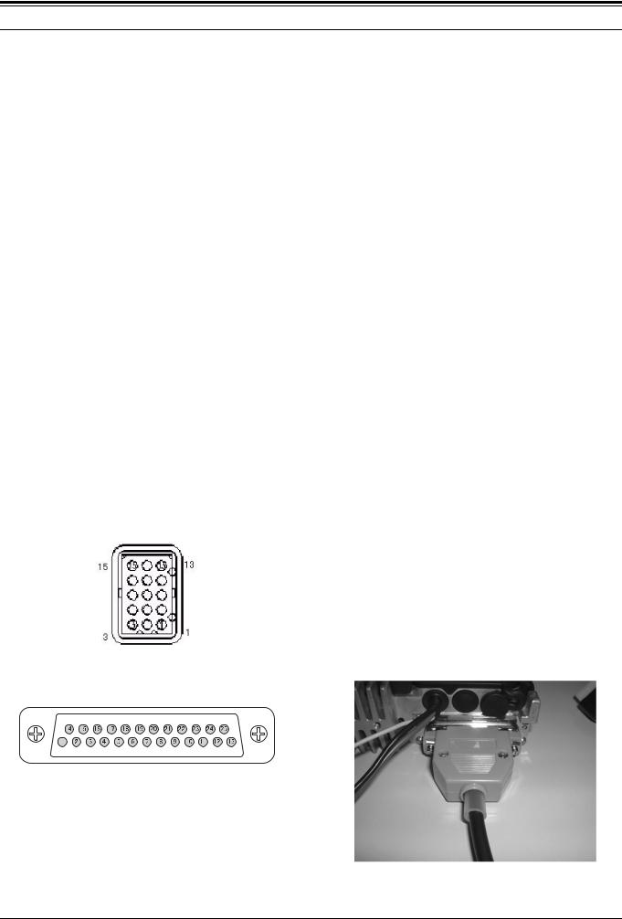
1.325-pin D-Sub ACC Connector
(TK-7180/ 8180 only)
The 25-pin ACC connector is located on the rear panel of the TK-7180/ 8180 transceivers and you can connect external devices, such as the KDS-100, to this connector.
Figure 1-2 25-pin D-Sub ACC Connector
Table 1-3 25-pin D-Sub ACC Connector Pin Assignment
Pin |
Signal |
Input/ Output |
Description |
|
number |
name |
|||
|
|
|||
|
|
|
|
|
|
|
|
|
|
1 |
NC/ RSSI |
- |
No Connection. |
|
RSSI can be sent after modification; Output level 0.8 - 2.3V). |
||||
|
|
|
||
|
|
|
|
|
|
|
|
Serial Data Input 1 |
|
2 |
RXD1 |
Input |
RS-232C Level, Input voltage range +/-30Vmax, |
|
|
|
|
L=less than 0.4V, H=more than 2.4V Zi=more than 5kohm |
|
|
|
|
|
|
3 |
TXD1 |
Output |
Serial Data Output 1 |
|
RS-232C Level, L=less than -5V, H=more than 5V Zo=more than 5kohm |
||||
|
|
|
||
|
|
|
|
|
|
|
|
Auxiliary I/O 9 |
|
4 |
AUX I/O 9 |
Input/ Output |
Input: Active Low with 47kohm Pull-Up to 5V, L=less than 0.8V, H=more than 4.2V |
|
Output: Active Low with 47kohm Pull-Up to 5V, 0.2mAmax, L=less than 0.3V, H=more than 4.8V |
||||
|
|
|
EMF |
|
|
|
|
|
|
|
|
|
Data Signal Input |
|
5 |
DI |
Input |
60% of System Deviation with 2Vp-p input (Data input level is adjustable), |
|
|
|
|
Input Impedance=10kohm or more, DC coupled, Frequency Response =+2/-3dB, |
|
|
|
|
|
|
6 |
MI2 |
Input |
External Mic Input: 60% Deviation with 1kHz 5.0+/-2.5mV Input signal |
|
|
|
|
|
|
7 |
GND |
- |
Ground |
|
|
|
|
|
|
8 |
AUX I/O 8 |
Input/ Output |
AUX I/O 8: Same Level as AUX I/O 9. |
|
|
|
|
|
|
9 |
TXD2 |
Output |
Serial Data Output 2: |
|
C MOS Level, L=less than 0.7V H=more than 4.2V with 25kohm load, Zo=more than 1kohm |
||||
|
|
|
||
|
|
|
|
|
10 |
RXD2 |
Input |
Serial Data Input 2 |
|
C MOS Level, Input voltage range=+5/0 Vmax, L=less than 0.8V H=more than 4.2V |
||||
|
|
|
||
|
|
|
|
|
11 |
GND |
- |
Ground |
|
|
|
|
|
|
12 |
AUX I/O 7 |
Input/ Output |
Auxiliary I/O 7: Same Level as AUX I/O 9. |
|
|
|
|
|
|
13 |
AUX I/O 6 |
Input/ Output |
Auxiliary I/O 6: Same Level as AUX I/O 9. |
|
|
|
|
|
|
14 |
SB |
- |
Power Output in conjunction with the Power Switch |
|
DC 13.6V +/-15% 2.0Amax |
||||
|
|
|
||
|
|
|
|
|
15 |
AUX OUT |
Output |
Auxiliary OUT 2 |
|
2 |
Active Low, Open collector 500mAmax, Defualt=None, L=less than 0.3V |
|||
|
|
|||
|
|
|
|
|
16 |
AUX OUT |
Output |
Auxiliary OUT 1 |
|
1 |
Active Low, Open collector 500mAmax, Defualt=None, L=less than 0.3V |
|||
|
|
|||
|
|
|
|
|
17 |
AFO |
Output |
RX Filtered Audio Output |
|
DC coupled, AF low level output 700mVp-p typ with standard modulated signal receiving. |
||||
|
|
|
||
|
|
|
|
|
18 |
GND |
- |
Ground |
|
|
|
|
|
|
19 |
DEO |
Output |
Detected Signal Output |
|
DC coupled, 740 mVp-p typ with standard moduration signal, AF output level is adjustable. |
||||
|
|
|
||
|
|
|
|
|
20 |
AUX I/O 5 |
Input/ Output |
Auxiliary I/O 5: Same Level as AUX I/O 9. |
|
|
|
|
|
|
21 |
AUX I/O 4 |
Input/ Output |
Auxiliary I/O 4: Same Level as AUX I/O 9. |
|
|
|
|
|
|
22 |
AUX I/O 3 |
Input/ Output |
Auxiliary I/O 3: Same Level as AUX I/O 9. |
|
|
|
|
|
|
23 |
AUX I/O 2 |
Input/ Output |
Auxiliary I/O 2: Same Level as AUX I/O 9. |
|
|
|
|
|
|
24 |
AUX I/O 1 |
Input/ Output |
Auxiliary I/O 1: Same Level as AUX I/O 9. |
|
|
|
|
|
|
25 |
ME |
- |
Mic Ground |
|
|
|
|
|
Version: 1.13 USA |
Modification Information |
3 |

1 TERMINAL FUNCTION
1.414-pin Universal Connector
(TK-2180/ 3180 only)
The 14-pin connector is available on the TK-2180/ 3180 transceivers and you can connect external devices to this connector.
14 12 10 8 6 4 2 13 11 9 7 5 3 1
|
|
|
Figure 1-3 14-pin Universal Connector |
|
|
|
|
Table 1-4 14-pin Universal Connector Pin Assignment |
|
|
|
|
|
|
Pin |
Name |
I/O |
Function |
|
number |
||||
|
|
|
||
|
|
|
|
|
1 |
SSW |
I |
Ext/Int Speaker Switch Input |
|
L=External Speaker On, H=Internal Speaker ON, Input Voltage= 0 - 5.0V |
||||
|
|
|
||
|
|
|
|
|
2 |
SP+ |
O |
BTL Output + for External Speaker |
|
Audio Output Power at Volume Max 1.3+/-0.5W 8ohm, 0.9+/-0.5W 16ohm (typ) |
||||
|
|
|
||
|
|
|
|
|
3 |
SP- |
O |
BTL Output - for External Speaker |
|
Audio Output Power at Volume Max 1.3+/-0.5W 8ohm, 0.9+/-0.5W 16ohm (typ) |
||||
|
|
|
||
|
|
|
|
|
4 |
MSW |
I |
Ext/ Int Mic Switch Input |
|
L=External Mic On, H=Internal Mic On, Input Voltage= 0 - 5.0V |
||||
|
|
|
||
|
|
|
|
|
|
|
|
Ext Mic Input |
|
5 |
EMC |
I |
Impedance=1.8kohm Audio Level; 60% system deviation with 7.5+/-2.5mVrms Input, |
|
|
|
|
Normal DC Voltage; 5.0+/-1V. |
|
|
|
|
|
|
6 |
ME |
- |
External Mic Ground |
|
|
|
|
|
|
7 |
PTT |
I |
External PTT Input; L=PTT On |
|
|
|
|
|
|
|
|
|
Programmable Function Key Input |
|
8 |
PF |
I |
Input voltage range; 0 - 5V (10kohm Pull-Up to 5V) |
|
|
|
|
Input Level; 5.0 to 4.4=None, 4.4 to 3.1V=PF1 key On, 3.1 to 2.3V= PF2 key On, 2.3 to 0V= PF1&2 key On |
|
|
|
|
|
|
|
|
|
AUX I/O port (for External Option) |
|
9 |
OPT |
I/O |
Man Down Input; H=more than 4.0V/ L=less than 1.0V (Range 0 to 5V) |
|
Serial Data Input; H=more than 4.0V/ L=less than 1.0V (Range 0 to 5V), Data speed=57600bps max |
||||
|
|
|
AUX Output; H=more than 4.7V/ L=less than 0.45V with 25kohm load. |
|
|
|
|
|
|
10 |
E |
- |
Ground |
|
|
|
|
|
|
11 |
5U |
- |
5 V Output (FPU programable), 140 mAmax |
|
|
|
|
|
|
12 |
TXD |
O |
Serial Data Output |
|
C MOS Level, H=more than 4.7V/ L=less than 0.45V with 25kohm load, Baud rate =57600bpd max |
||||
|
|
|
||
|
|
|
|
|
13 |
RXD |
I |
Serial Data Input |
|
C MOS Level, H=more than 4.0V/ L=less than 1.0V (Range 0 to 5V), Baud rate =115200bpd max |
||||
|
|
|
||
|
|
|
|
|
14 |
NC (E) |
- |
Not use (GND) |
|
|
|
|
|
4 |
Modification Information |
Version: 1.13 USA |
1 TERMINAL FUNCTION
1.5Front Panel Terminal
(TK-7180/ 8180 only)
The front panel terminal is equipped with the 14-pin connector.
Table 1-5 The Front Panel Terminal Pin Assignment
Pin |
Name |
I/O |
Function |
|
number |
||||
|
|
|
||
|
|
|
|
|
|
|
|
|
|
1 |
SPI |
I |
Front Panel Speaker Input |
|
|
|
|
|
|
2 |
GND |
- |
Ground |
|
|
|
|
|
|
3 |
8C |
- |
8 V Power Supply |
|
|
|
|
|
|
4 |
SB |
- |
Power Supply (Switched B) |
|
|
|
|
|
|
5 |
RA |
O |
Audio Output (for SP-MIC) |
|
|
|
|
|
|
6 |
PSW |
I |
Power Switch Control Input |
|
|
|
|
|
|
7 |
MIC |
I |
Mic Input |
|
|
|
|
|
|
8 |
ME |
- |
Mic Ground |
|
|
|
|
|
|
9 |
PSENS |
I |
Panel Sens. Input |
|
|
|
|
|
|
10 |
TXD |
O |
Serial Data Output |
|
|
|
|
|
|
11 |
RXD |
I |
Serial Data Input |
|
|
|
|
|
|
12 |
GND |
- |
Ground |
|
|
|
|
|
|
13 |
SHIFT |
O |
Beat Shift Output |
|
|
|
|
|
|
14 |
RST2 |
O |
Sub-u com Reset Output |
|
|
|
|
|
1.6Modification of Serial Port Level
(TK-7180/ 8180 only)
The TXD2 and RXD2 of the 25-pin connectors are configured at the C MOS level (0/ 5 V) as a factory default setting.
You can convert the level to the RS232 level (±12 V) by configuring the port. The following procedures shows how to change the serial port level to the RS232 level.
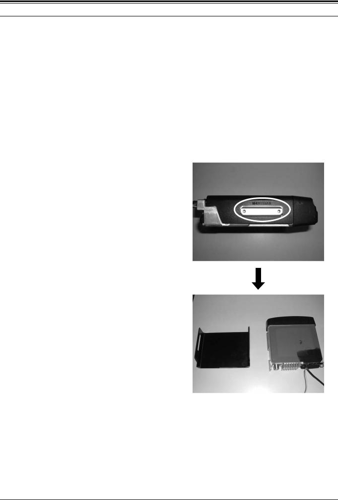
1.Remove the top cover of the TK-7180/ 8180 transceiver.
•Lift the top cover by widening two side tabs. Then, pull upward to remove the top cover from the transceiver body.
Version: 1.13 USA |
Modification Information |
5 |

1 TERMINAL FUNCTION
• Remove the top packing. |
2. Remove the R622, R621, R625, R630, R629, R636 |
|
(A) Chip Jumpers (R92-0670-x5), and add the Chip |
|
Jumpers to R626, R627, R628, R631, R634, R637 |
|
(B). |
•Remove 4 screws and the shielding plate.
A
B
3.Install the shield plate, upper packing and upper case to the transceiver.
6 |
Modification Information |
Version: 1.13 USA |
1 TERMINAL FUNCTION
Version: 1.13 USA |
Modification Information |
7 |
2 CONNECT OPTIONAL DEVICES
2.1Ignition Sense Cable
(TK-7180/ 8180 only)
Connect the Ignition Sense Cable (KCT-46) to the TK-7180/ 8180 transceivers.
2.1.1 Description
This product is the ignition sense cable for the TK-7180/ 8180 transceivers.
2.1.2 Features
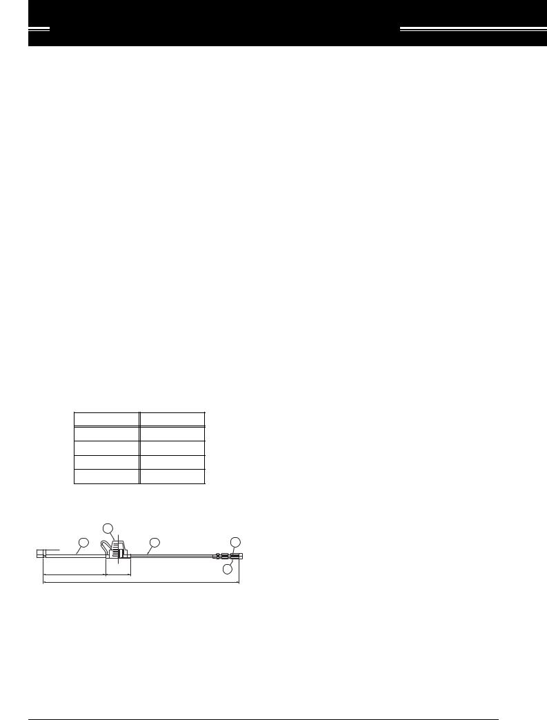
•The cable length is 320 cm (10.5 ft).
•The cable has a plug-shaped terminal on the transceiver side and the terminal is covered by a plastic cap to avoid the short-circuit. The vehicle side cable has no plug (a bare wire).
•The mini-sized blade fuse (3 A) and the water-proof fuse holder are used for the cable to provide the water-proof holder.
2.1.3 Mechanical Specifications
! Product Dimensions and Weight
Table 2-1 Product Dimensions and Weight
|
|
Item |
|
|
|
|
|
Length |
|
320 cm (10.5ft) |
|
|
|
Width |
|
- |
|
|
|
Thickness |
|
- |
|
|
|
Weight |
|
60 g |
|
! Cable Specifications |
|
||||
|
|
2 |
|
|
|
15 |
(4) |
1 |
|
1 |
3 |
|
|
|
|
||
|
|
230 –20 |
40 |
|
4 |
|
|
|
|
3200 –50 |
|
|
|
Figure 2-1 Mechanical Parts |
|
||
Table 2-2 Mechanical Parts
No. |
Part Name |
Qty |
Remarks |
||
|
|
|
|
|
|
|
|
|
|
|
|
1 |
Lead Wire |
1 |
UL1015 AWG18, 19A max, |
||
Color: Yellow |
|||||
|
|
|
|
||
|
|
|
|
|
|
|
|
Body |
1 |
PVC, Color: Black |
|
|
|
|
|
|
|
2 |
Mini Blade |
Terminal |
2 |
Terminal: TCQ21 |
|
Fuse Holder |
|
|
|
||
Holder |
1 |
- |
|||
|
|
Cap |
|||
|
|
|
|
||
|
|
|
|
|
|
3 |
Bullet Terminal Rec |
1 |
300541 (or Similar) |
||
|
|
|
|
||
4 |
Conductor Sleeve |
1 |
- |
||
|
|
|
|
|
|
2.1.4 Standard Specifications
"Display
No remarks.
2.1.5 Supplied Accessories
Table 2-3 Supplied Accessories
No. |
Name |
Part |
Qty. |
Remarks |
|
Number |
|||||
|
|
|
|
||
|
|
|
|
|
|
|
|
|
|
|
|
1 |
Mini blade Fuse |
- |
1 |
3 A |
|
|
|
|
|
|
2.1.6 Installing KCT-46 Cable
1.Open the KCT-46 fuse folder and insert the mini blade fuse (3 A).
|
8 |
Modification Information |
Version: 1.13 USA |
|
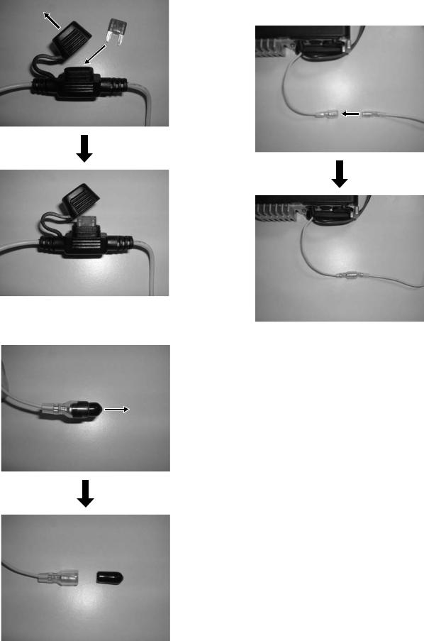
2.Remove the shielding cover of the yellow cable terminal.
3.Connect the plug-form end of the KCT-46 cable to the yellow cable terminal of the transceiver.
4.Connect the other end of the KCT-46 cable to the Ignition Line of the vehicle.
2 CONNECT OPTIONAL DEVICES
2.2KCT-40 Cable
(TK-7180/ 8180 only)
You can install the connection cable (KCT-40) for external devices to the TK-7180/ 8180 transceivers. This section describes how to connect the KCT-40 cable to the TK7180/ 8180 transceivers.
2.2.1 Description
This product is the connection cable or external devices prepared for the TK-7180/ 8180 transceivers.
2.2.2 Features
•The cable length is 40 cm (1.3 ft).
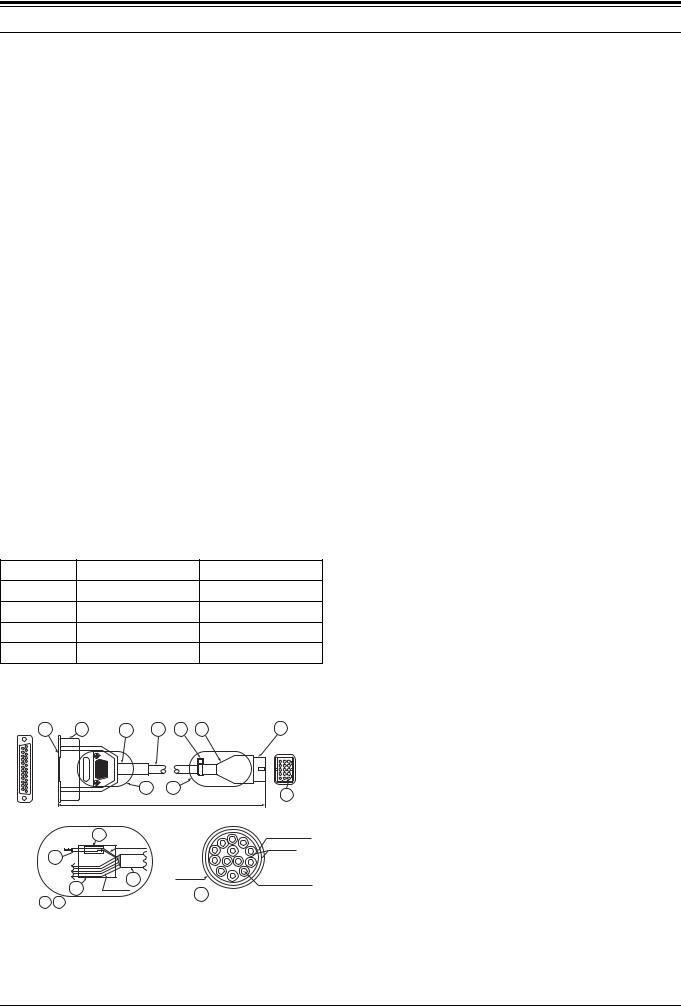
•One end of the cable has the D-sub 25-pin connector (transceiver side) and the other end has the Molex 15pin connector (KDS-100 or KGP-2A/ KGP-2B side).
•The Molex 15-pin connector is equipped with the dustproof cover.
2.2.3 Mechanical Specifications
! Product Dimensions and Weight
Table 2-4 Product Dimensions and Weight
Item |
|
Connector |
|
|
Cable Length |
|
Length |
|
55 mm |
|
|
40 cm/ 1.3 ft |
|
Width |
|
47.5 mm |
|
|
|
|
Thickness |
|
16.5 mm |
|
|
|
|
Weight |
|
60 g |
|
|
|
|
! Cable Specifications |
|
|
|
|||
4 |
5 |
10 |
7 |
11 |
3 |
1 |
|
|
A |
|
B |
|
2 |
|
|
|
400 –30 |
|
||
|
|
|
|
|
||
|
|
|
|
8 |
|
Spiral Shield |
|
|
|
|
|
Spiral Shield |
|
Insulator |
|
|
6 |
|
Cable |
|
|
||
|
|
|
|
|
|||
|
A Side Terminal |
|
|
|
|
||
|
No. 7 |
|
|
7 |
Max φ 6.4 |
|
|
|
B Side Terminal |
|
Conductor |
||||
|
No. 3 |
|
9 |
|
UL1571AWG26 x 13 |
||
|
|
|
Cable x 11 |
7 |
Cable Spec |
||
|
|
|
|
||||
Detail |
A |
B : Connection Process |
|||||
|
|
||||||
Figure 2-2 Mechanical Parts
Table 2-5 Mechanical Parts
No. |
Part Name |
Qty |
Remarks |
|
|
|
|
|
|
|
|
|
|
|
1 |
Housing |
1 |
MOLEX: 39-03-3157 |
|
|
|
|
|
|
2 |
Terminal |
14 |
MOLEX: 1855T (L) |
|
|
|
|
|
|
3 |
Cover |
1 |
521156 |
|
|
|
|
|
|
4 |
D-sub Connector |
1 |
Used inch screw |
|
(No. 4 - 40UNC) |
||||
|
|
|
||
|
|
|
|
|
5 |
D-sub Cover Set |
1 |
CD4225H0*00 |
|
|
|
|
|
|
6 |
Cable |
2 |
UL1007AWG26 |
|
Color: Black Length: 30 mm |
||||
|
|
|
||
|
|
|
|
|
|
|
|
UL1007AWG26 |
|
7 |
Cable |
1 |
13-pin Shield cable Length: |
|
|
|
|
400 mm |
|
|
|
|
|
|
8 |
Heat Shrink Tube |
2 |
Sumi Tube φ 2.0 x 14 mm |
|
|
|
|
|
|
9 |
Heat Shrink Tube |
2 |
Sumi Tube φ 7.0 x 20 mm |
|
|
|
|
|
|
10 |
Tube |
1 |
Rubber φ 9.0 Clearwhite |
|
|
|
|
|
|
11 |
Cable Tie |
1 |
Color: Black |
|
|
|
|
|
2.2.4 Electrical Specifications
! Terminal Specifications
Table 2-6 Terminal Specifications
Pin No. |
Function |
Specification |
|
D-Sub25 |
|
|
|
|
|
|
|
1 |
- |
- |
|
|
|
|
|
2 |
- |
- |
|
|
|
|
|
3 |
- |
- |
|
|
|
|
|
4 |
- |
- |
|
|
|
|
|
|
|
Data Signal Input: |
|
5 |
DI |
60% system daviation with 2Vp-p Input/ |
|
|
|
Impedance=10kohm, Non Pre-emphasis |
|
|
|
|
|
6 |
- |
- |
|
|
|
|
|
7 |
GND |
Ground |
|
|
|
|
|
|
|
47kohm Pull-Up to 5V |
|
8 |
AIO8 |
Input: L < 0.8V, H > 4.2V |
|
|
|
Output: 0.2mAmax, L< 0.3V, H> 4.8Vemf |
|
|
|
|
|
|
|
Serial Data Output 2: |
|
9 |
TXD2 |
TTL Level, L < 0.7V H > 4.2V with |
|
|
|
25kohm load, Zo > 1kohm |
|
|
|
|
|
10 |
RXD2 |
Serial Data Input 2: |
|
TTL Level(+5/0 Vmax), L< 0.8V H> 4.2V |
|||
|
|
||
|
|
|
|
11 |
- |
- |
|
|
|
|
|
12 |
AIO7 |
Same as Pin No.8 |
|
|
|
|
|
13 |
AIO6 |
Same as Pin No.8 |
|
|
|
|
|
14 |
SB |
Switched Battery Voltage |
|
DC 13.6V +/-15% 2.0Amax |
|||
|
|
||
|
|
|
|
15 |
- |
- |
|
|
|
|
|
16 |
- |
- |
|
|
|
|
|
10 |
Modification Information |
Version: 1.13 USA |
|
2 CONNECT OPTIONAL DEVICES
Pin No. |
Function |
Specification |
D-Sub25 |
||
|
|
|
|
|
|
17 |
- |
- |
|
|
|
18 |
- |
- |
|
|
|
|
|
Detected Signal Output |
19 |
DEO |
740 mVp-p with standard moduration |
|
|
Non De-emphasis/ Non Squelched |
|
|
|
20 |
AIO5 |
Same as Pin No.8 |
|
|
|
21 |
AIO4 |
Same as Pin No.8 |
|
|
|
22 |
AIO3 |
Same as Pin No.8 |
|
|
|
23 |
AIO2 |
Same as Pin No.8 |
|
|
|
24 |
AIO1 |
Same as Pin No.8 |
|
|
|
25 |
- |
- |
|
|
|
2.2.5 Standard Specifications
"Display Specifications No remarks.
2.2.6 Supplied Accessories
No Supplied Accessory.
2.2.7 Connector Location
The following table explains how to interface with other peripherals.
D-sub 25-pin |
|
Molex 15-pin |
KDS-100/ |
|
Function |
KGP-2A/B |
|||
Pin number |
Pin number |
|||
|
Function |
|||
|
|
|
||
|
|
|
|
|
|
|
|
|
|
3 |
- |
- |
- |
|
|
|
|
|
|
4 |
- |
- |
- |
|
|
|
|
|
|
5 |
DI |
5 |
DO |
|
|
|
|
|
|
6 |
- |
- |
- |
|
|
|
|
|
|
7 |
GND |
3 |
GND |
|
|
|
|
|
|
8 |
AIO8 |
9 |
TXS/ LOK |
|
|
|
|
|
|
9 |
TXD3 |
15 |
RXD |
|
|
|
|
|
|
10 |
RXD3 |
14 |
TXD |
|
|
|
|
|
|
11 |
- |
- |
- |
|
|
|
|
|
|
12 |
AIO7 |
11 |
MIM |
|
|
|
|
|
|
13 |
AIO6 |
6 |
PTT |
|
|
|
|
|
|
14 |
SB |
1 |
SB |
|
|
|
|
|
|
15 |
- |
- |
- |
|
|
|
|
|
|
16 |
- |
- |
- |
|
|
|
|
|
|
17 |
- |
- |
- |
|
|
|
|
|
|
18 |
- |
- |
- |
|
|
|
|
|
|
19 |
DEO |
4 |
DI |
|
|
|
|
|
|
20 |
AIO5 |
8 |
SQ |
|
|
|
|
|
|
21 |
AIO4 |
10 |
AM |
|
|
|
|
|
|
22 |
AIO3 |
13 |
DISP OFF |
|
(KPG-2A/ 2B) |
||||
|
|
|
||
|
|
|
|
|
23 |
AIO2 |
12 |
- |
|
|
|
|
|
|
24 |
AIO1 |
7 |
DTC |
|
|
|
|
|
|
25 |
- |
- |
- |
|
|
|
|
|
Figure 2-3 15Pin Molex Connecter
Figure 2-4 25Pin D-Sub Connector
Table 2-7 KCT-40 Cable Connector Pin Assignment
D-sub 25-pin |
|
Molex 15-pin |
KDS-100/ |
|
Function |
KGP-2A/B |
|||
Pin number |
Pin number |
|||
|
Function |
|||
|
|
|
||
|
|
|
|
|
|
|
|
|
|
1 |
- |
- |
- |
|
|
|
|
|
|
2 |
- |
- |
- |
|
|
|
|
|
2.2.8 Connecting KCT-40 Cable
1.Remove the cap for accessory on the rear panel of the transceiver.
2.Connect the KCT-40 cable to the D-sub 25-pin connector on the rear side of the transceiver.
|
Version: 1.13 USA |
Modification Information |
11 |
|

2 CONNECT OPTIONAL DEVICES
2.3KDS-100
(TK-7180/ 8180 only)
You can connect the data terminal (KDS-100) to the TK7180/ 8180 transceivers to make data communications. This section describes how to connect the KDS-100 to the TK-7180/ 8180 transceivers.
2.3.1 Description
This transceiver can be configured to work with a data terminal used to perform data transmission. This transceiver is equipped with serial input/ output and data modulation input/ output terminals. FleetSync compatible mobile transceivers,Kenwood TK-7100/ 8100/ 780/ 880/ 7150/ 8150/7180/ 8180/ x60G series or etc, support the KDS-100.
Also, this KDS-100 is equipped with DSP (Digital Signal Processing), general purpose serial ports, and general purpose I/O ports. Thus, it has been designed to work with various peripheral devices. Although we provide the FPU (programming software KPG-71D).
2.3.2 Features of KDS-100
•Full-dot display (240 x 64 dots) with backlight function
•A dealer programmable PF keys (Programmable Function Key) with backlight function
•The following external terminals are available.
-Serial communication terminal
-I/ O control terminal
-Data modulation I/ O terminals
•The following internal terminals are available.
-Two general purpose serial ports (compatible with the RS-232C signal level)
-PC/ AT keyboard input terminal (ask R&D )
-NMEA0183 GPS receiver connection terminal
-Input terminal for differential GPS signal to transfer to the GPS equipment.
-Two clock synchronizer serial input terminals (for low-cost card reader) (ask R&D)
-General purpose I/O control terminals
•DSP for supporting high speed data communication
•Real time clock
•Battery status memory for data communication
•Tri-color LED indicating the communication port status
•Modem output level adjustment function using the command generated from the electronic volume (PC & Panel Tune)
•Firmware update function using a flash ROM
•This transceiver supports the following protocols.
-Fleet-Sync protocol capable (Non-FleetSync capable LTR/ Conventional transceivers can be yet interfaced with FleetSync compatible MDT to work. i.e.TK-*60G)
-FleetSync serial protocol 1 (for full FleetSync PC protocol 1 compatible transceiver. i.e. TK-780/880)
-FleetSync serial protocol 2 (for full FleetSync PC protocol 2 compatible transceiver. i.e. TK-7180/ 8180)
•Internal alarm to notify the message reception
•Advanced message function utilizing the FleetSync Short/ Long Message
•PTT ID Display
•GPS Auto/Polling capability (Install GPS unit into the KDS-100 or Transciver)
•Radio Remote (For PC2 Protocol compatible Radio)
•PTT ID Display and Log backup
•Emergency Feature Capability (For PC2 protocol)
2.3.3 Mechanical Specifications
! Product Dimensions and Weight
Table 2-8 Product Dimensions and Weight
Item |
|
Body |
|
|
|
|
|
A |
|
B |
|
|
|
||
|
|
|
|
|
|
|
|
Width |
187 mm |
|
187 mm |
|
|
|
|
Depth |
42 mm |
|
46.5 mm |
|
|
|
|
Height |
88 mm |
|
88 mm |
|
|
|
|
Weight |
|
0.50 kg |
|
|
|
|
|
A:Dimension without projections
B:Dimension including projections
!Front Panel
•Key Layout: 9-key top set with rubber having LED backlight
•Display: 240 x 64 positive type full-dot matrix LCD with LED backlight
•LED: Tri-color LED
•Pigtail connection cable (15-pin Molex)
!Rear Panel
•Screw hole for mobile bracket (4 mm screw)
•Connector for external devices
|
12 |
Modification Information |
Version: 1.13 USA |
|
2 CONNECT OPTIONAL DEVICES
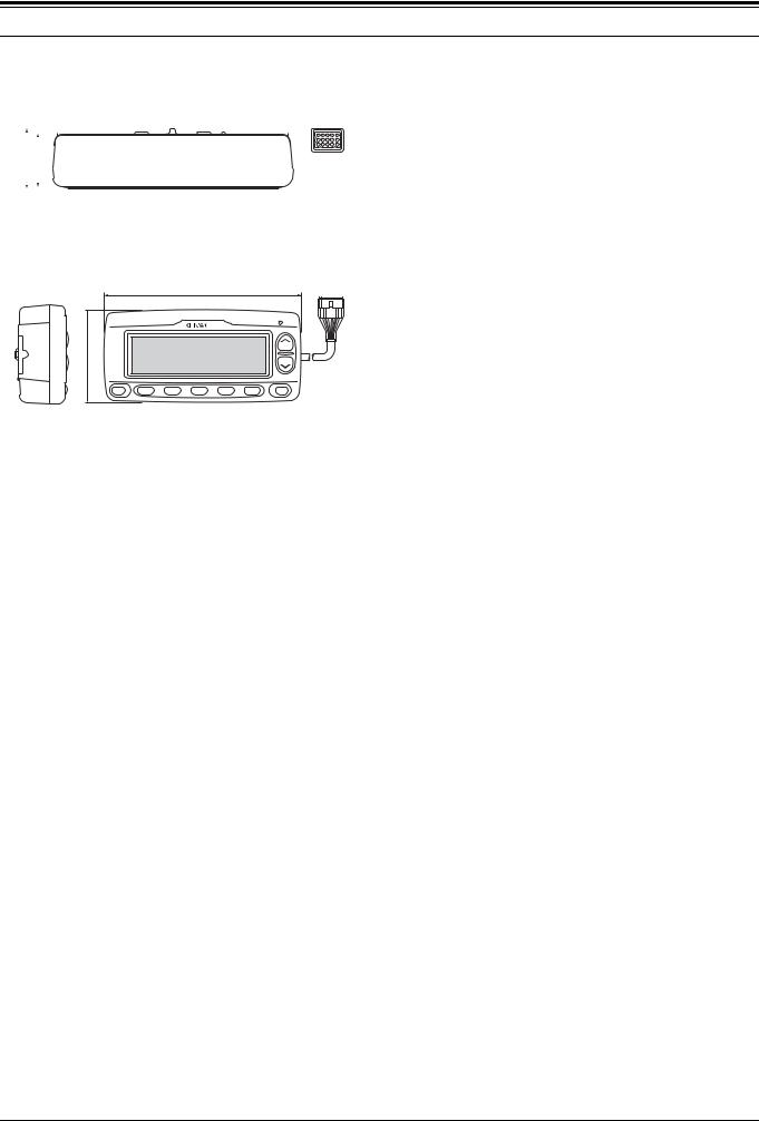
2.3.4 Appearance
! Top Panel
46.5 |
|
|
|
|
|
|
|
|
|
|
|
|
|
|
|
|
|
|
|
|
|
|
|
|
|
|
|
42 |
|
|
|
|
|
|
|
|
|
|
|
|
|
|
|
|
|
|
|
|
|
|
|
|
|
|
|
|
|
|
|
|
|
|
|
|
|
|
|
|
|
|
|
|
|
|
|
|
|
|
||
|
|
|
|
|
|
|
|
|
|
|
|
|
|
|
|
|
|
|
|
|
|
|
|
|
|
|
Figure 2-5 Top Panel
! Side Panel and Front Panel
187 |
88
MENU |
1 |
2 |
3 |
4 |
5 |
SEL |
Figure 2-6 Side Panel and Front Panel
2.3.5 Electrical Specifications
! Modulation
Table 2-9 Modulation Type
No. |
Item |
Description |
|
|
|
|
|
|
1 |
Modulation |
Minimum Shift Keying (MSK) |
|
|
|
2 |
Baud Rate |
1200/ 2400 bps |
|
|
|
! General Specifications
Measured and inspected under the standard conditions unless it is noted.
Table 2-10 General Specifications
No. |
Item |
Description |
|
|
|
|
|
|
|
|
|
|
|
Nominal Power Voltage: DC 13.6 V |
|
1 |
Power Voltage |
Negative Ground |
|
|
|
Range: DC 10.0 V - 15.7 V |
|
|
|
|
|
2 |
Temperature |
-20°C to +60°C |
|
Range |
|||
|
|
||
|
|
|
|
3 |
Measurement |
KIS 58-01: The transceiver is |
|
Environment |
measured and tested under the |
||
|
product inspection specifications. |
||
|
|
||
|
|
|
|
|
Low frequency |
KIS 58-01: The transceiver is |
|
4 |
measured and tested under the |
||
|
output |
product inspection specifications. |
|
|
|
||
|
|
|
|
5 |
Alarm Output |
16 ohm |
|
Impedance |
|||
|
|
||
|
|
|
|
6 |
Modem Outpu |
600 ohm |
|
|
Impedance |
|
|
7 |
Modem Input |
600 ohm |
|
|
Impedance |
|
! Electrical Specifications
Table 2-11 Electrical Specifications
No. |
Item |
Measurement |
Spec. |
|
Condition |
||||
|
|
|
||
|
|
|
|
|
|
|
|
|
|
1 |
Modem Encode |
DO: 511random |
700+/- |
|
defualt Level |
pattern/ 600ohm |
20mVrms |
||
|
||||
|
|
|
|
|
2 |
Modem Encode |
DO: 1200Hz/ |
100 - 1000 |
|
Level Range |
600ohm |
mVrms |
||
|
||||
|
|
|
|
|
3 |
Modem Decode |
DI: 1200Hz/ |
100 - 1000 |
|
Level Range |
600ohm |
mVrms |
||
|
||||
|
|
|
|
|
4 |
Retaining period for |
Lithium Battery Fully |
Above 2 |
|
the received data |
charged & GPS |
months |
||
|
backup 30 µA |
|||
|
|
|
||
|
|
|
|
|
|
Consumption |
|
|
|
5 |
Current for Storing |
Without GPS unit |
Below 50uA |
|
|
the received data |
|
|
|
|
|
|
|
|
6 |
Bit Error Rate |
DI: 700 mVrms |
Below 0.5% |
|
(1200 bps) |
12dB SINAD level |
|||
|
|
|||
|
|
|
|
|
7 |
Bit Error Rate |
DI: 700 mVrms |
Below 0.5% |
|
(2400 bps) |
12 dB SINAD level |
|||
|
|
|
|
|
|
Consumption |
INT/ EXT SP Max. |
Below 700 |
|
8 |
When the INT/ EXT |
|||
current |
mA |
|||
|
SP are at maximum. |
|||
|
|
|
||
|
|
|
|
|
|
|
Frequency Stability |
5+/-25ppm |
|
|
|
(1 min/ |
||
|
|
(25°C) |
||
|
|
Month) |
||
|
Real time clock |
|
||
9 |
|
|
||
Temperature |
|
|||
accuracy |
|
|||
|
Characteristic |
+10/-120 |
||
|
|
|||
|
|
-10 to +70°C |
ppm |
|
|
|
25°C Reference |
|
|
|
|
|
|
2.3.6 Optional Accessories
Table 2-12 Optional Accessories
No. |
Model Name |
Name (Specifications) |
|
|
|
|
|
|
|
|
|
1 |
KPG-46 |
Programming Interface Cable |
|
(8-pin modular) |
|||
|
|
||
|
|
|
|
|
KPG-71D |
Field Programming Software |
|
2 |
(For PC2 protocol; |
||
(FPU) |
|||
|
ver3.10 or later) |
||
|
|
||
|
|
|
|
3 |
KCT-34 |
Transceiver Interface Cable |
|
(for TK-780/880 mobile ) *1 |
|||
|
|
||
4 |
KCT-35 |
Transceiver Interface Cable |
|
(for TK-x60 series mobile ) *1 |
|||
|
|
||
5 |
KCT-39 |
Transceiver Interface Cable |
|
(for TK-7100/8100 mobile ) *1 |
|||
|
|
||
6 |
KCT-40 |
Transceiver Interface Cable |
|
(for TK-7150/8150/7180/8180) *1 |
|||
|
|
||
7 |
KCT-36 |
Extension Cable *1 |
*1 Common option to the KGP-2A/ 2B (Modem GPS Receiver/ Controller)
|
Version: 1.13 USA |
Modification Information |
13 |
|
 Loading...