


 Loading...
Field Programming Reference
For
TK-2180/ 3180/ 7180/ 8180
Version: |
1.11 |
Last Updated: |
Aug, 2004 |
Language: |
English |
Type: |
K |

1.
1 SETTING UP THE KPG-89D...................... |
1 |
|
1.1 |
System Requirements..................................... |
1 |
1.2 |
Connecting the Transceiver to the PC ............ |
1 |
1.3 |
Installing the KPG-89D ................................... |
1 |
1.4 |
Uninstalling the KPG-89D ............................... |
2 |
2 BASIC OPERATION................................... |
3 |
|
2.1 |
Starting and Exiting the KPG-89D .................. |
3 |
2.2 |
Initializing the Window .................................... |
3 |
2.3Writing the Configuration Data to the Transceiv-
|
er ....................................................................... |
3 |
2.4 |
Modifying the Configuration Data.................... |
3 |
2.5Editing the Configuration Data and Writing to
|
the Transceiver ................................................. |
3 |
2.6 |
Displaying Help ............................................... |
4 |
3 MENU DESCRPTION ................................. |
5 |
||
3.1 |
Main Window .................................................. |
5 |
|
|
3.1.1 |
Title Bar ....................................................... |
5 |
|
3.1.2 |
Menu Bar ..................................................... |
5 |
|
3.1.3 |
Toolbar......................................................... |
5 |
|
3.1.4 |
Status Bar .................................................... |
6 |
3.2 |
Menu Command Description .......................... |
6 |
|
|
3.2.1 |
File Menu ..................................................... |
6 |
|
3.2.2 |
Model Menu ................................................. |
6 |
|
3.2.3 |
Edit Menu..................................................... |
7 |
|
3.2.4 |
Program Menu ............................................. |
7 |
|
3.2.5 |
Tools Menu .................................................. |
7 |
|
3.2.6 |
Setup Menu ................................................. |
8 |
|
3.2.7 |
View Menu ................................................... |
8 |
|
3.2.8 |
Window Menu .............................................. |
8 |
|
3.2.9 |
Help Menu ................................................... |
8 |
3.3 |
Shortcut Keys.................................................. |
9 |
|
|
3.3.1 |
Menu Bar Operation .................................... |
9 |
|
3.3.2 |
File Menu Operation .................................... |
9 |
3.3.3Zone Information (Conventional Group) Win-
|
dow.................................................................. |
9 |
3.3.4 |
Zone Information (Trunking System) Window |
|
|
9 |
|
3.3.5 |
Program Menu ........................................... |
10 |
3.3.6 |
Help Menu1 ................................................. |
0 |
4 FILE MENU............................................... |
11 |
||
4.1 |
New............................................................... |
|
11 |
4.2 |
Open ............................................................. |
|
11 |
4.3 |
Save.............................................................. |
|
12 |
4.4 |
Save As......................................................... |
12 |
|
4.5 |
Print............................................................... |
|
13 |
|
4.5.1 |
Print List Item............................................. |
13 |
|
4.6 |
Print Preview................................................. |
16 |
|
|
|
4.6.1 |
Toolbar in the Print Preview ....................... |
16 |
|
4.7 |
Exit |
................................................................ |
17 |
5 |
MODEL .........................................MENU |
18 |
||
|
5.1 |
Model .........................................Information |
18 |
|
|
|
5.1.1 .............................................. |
Model Name |
18 |
|
|
5.1.2 .................................................. |
Frequency |
18 |
6 |
EDIT MENU .............................................. |
19 |
||
|
6.1 |
Zone .............................Information Window |
19 |
|
6.1.1Common to Conventional Group/Trunking
|
|
System .......................................................... |
19 |
|
6.1.2 |
Conventional Group................................... |
19 |
|
6.1.3 |
Trunking System........................................ |
23 |
6.2 |
Zone Edit Window (Conventional Group) ..... |
25 |
|
|
6.2.1 |
Zone Name ................................................ |
25 |
|
6.2.2 |
Data Zone-CH/GID .................................... |
26 |
|
6.2.3 |
Home Channel........................................... |
26 |
|
6.2.4 |
Home Channel Operator Selectable.......... |
26 |
|
6.2.5 |
Optional Signaling Decode Condition ........ |
26 |
|
6.2.6 |
Audio Control ............................................. |
26 |
|
6.2.7 |
Time-out Timer (TOT)................................ |
27 |
|
6.2.8 |
TOT Pre-alert............................................. |
27 |
|
6.2.9 |
TOT Rekey Time ....................................... |
27 |
|
6.2.10 |
TOT Reset Time...................................... |
27 |
|
6.2.11 |
BCL Override........................................... |
28 |
|
6.2.12 |
Zone Add................................................. |
28 |
|
6.2.13 |
Scan List.................................................. |
28 |
|
6.2.14 |
Table Button ............................................ |
28 |
|
6.2.15 |
Scan List Table Window.......................... |
28 |
6.3 |
Channel Edit Window.................................... |
28 |
|
|
6.3.1 |
Zone (Conventional Group) ....................... |
29 |
|
6.3.2 |
Channel ..................................................... |
29 |
|
6.3.3 |
Receive Frequency.................................... |
29 |
|
6.3.4 |
Transmit Frequency................................... |
29 |
|
6.3.5 |
QT/DQT Dec (Decode) .............................. |
30 |
|
6.3.6 |
QT/DQT Enc (Encode) .............................. |
30 |
|
6.3.7 |
Channel Name........................................... |
30 |
|
6.3.8 |
Transmit Power.......................................... |
30 |
|
6.3.9 |
Wide/ Narrow ............................................. |
31 |
|
6.3.10 |
Optional Signaling ................................... |
31 |
|
6.3.11 |
Busy Channel Lockout ........................... |
31 |
|
6.3.12 |
PTT ID ..................................................... |
31 |
|
6.3.13 |
Beat Shift................................................. |
32 |
|
6.3.14 |
Scan Add................................................. |
32 |
|
6.3.15 |
Compander.............................................. |
32 |
|
6.3.16 |
Data......................................................... |
32 |
|
6.3.17 |
Voice Scrambler ...................................... |
33 |
|
6.3.18 |
Scrambler Code ...................................... |
33 |
|
6.3.19 |
Channel Copy ([Shift] + [F3])................... |
33 |
|
6.3.20 |
Frequency Copy ([Shift] + [F4]) ............... |
33 |
|
6.3.21 |
QT/DQT Copy ([Shift] + [F5]) .................. |
34 |
6.4 |
Repeater Information Window ...................... |
34 |
|
|
6.4.1 |
Area Code.................................................. |
34 |
|
6.4.2 |
Home Repeater ......................................... |
35 |
|
6.4.3 |
Receive Frequency.................................... |
35 |
I

1.
|
6.4.4 |
Transmit Frequency................................... |
35 |
|
6.4.5 |
Beat Shift ................................................... |
35 |
|
6.4.6 |
TEL ............................................................ |
36 |
6.5 |
Zone Edit Window......................................... |
36 |
|
|
6.5.1 |
Zone Name ................................................ |
36 |
|
6.5.2 |
Scan Weight .............................................. |
36 |
|
6.5.3 |
Wide/ Narrow ............................................. |
36 |
|
6.5.4 |
Data Zone-CH/GID .................................... |
36 |
|
6.5.5 |
Data Delay Time ........................................ |
37 |
|
6.5.6 |
Home GID.................................................. |
37 |
|
6.5.7 |
Home GID Operator Selectable................. |
37 |
|
6.5.8 |
Time-out Timer (Dispatch) ......................... |
37 |
|
6.5.9 |
Time-out Timer (Telephone) ...................... |
37 |
|
6.5.10 |
Audio Control........................................... |
38 |
|
6.5.11 |
Encode Data Type................................... |
38 |
|
6.5.12 |
Zone Add................................................. |
38 |
|
6.5.13 |
Scan List.................................................. |
38 |
|
6.5.14 |
Table Button ............................................ |
38 |
|
6.5.15 |
Auto Telephone Search........................... |
38 |
|
6.5.16 |
TA Busy Channel Lockout....................... |
39 |
|
6.5.17 |
TA Key..................................................... |
39 |
|
6.5.18 |
ID (Fix ID) ................................................ |
39 |
|
6.5.19 |
Call Indicator (Fix ID)............................... |
39 |
|
6.5.20 |
Optional Signaling (Fix ID) ...................... |
39 |
6.5.21Horn Alert (Fix ID)(TK-7180/ 8180 only).. 39
|
6.5.22 |
Telephone (Block IDs)............................. |
40 |
|
6.5.23 |
Transmit Inhibit (Block IDs) .................... |
40 |
|
6.5.24 |
Decode (Block IDs) ................................. |
40 |
|
6.5.25 |
Scan List Table Window.......................... |
40 |
6.6 |
GID Edit Window........................................... |
41 |
|
|
6.6.1 |
Zone (Trunking System) ............................ |
41 |
|
6.6.2 |
GID ............................................................ |
41 |
|
6.6.3 |
Encode ID .................................................. |
41 |
|
6.6.4 |
Decode ID.................................................. |
41 |
|
6.6.5 |
GID Name.................................................. |
42 |
|
6.6.6 |
Transmit Power.......................................... |
42 |
|
6.6.7 |
Optional Signaling...................................... |
42 |
|
6.6.8 |
PTT ID ....................................................... |
42 |
|
6.6.9 |
Call Indicator.............................................. |
43 |
|
6.6.10 |
Horn Alert (TK-7180/ 8180 only) ............. |
43 |
|
6.6.11 |
Scan Add................................................. |
43 |
|
6.6.12 |
Transpond ............................................... |
43 |
|
6.6.13 |
Talk Around ............................................. |
43 |
|
6.6.14 |
Compander.............................................. |
43 |
|
6.6.15 |
Data......................................................... |
44 |
|
6.6.16 |
Voice Scrambler ...................................... |
44 |
|
6.6.17 |
Scrambler Code ...................................... |
44 |
|
6.6.18 |
GID Copy ([Shift] + [F3]).......................... |
44 |
6.7 |
Optional Features Window............................ |
45 |
|
|
6.7.1 |
Common-Page 1 Tab ................................ |
45 |
|
6.7.2 |
Common-Page 2 Tab ................................ |
49 |
|
6.7.3 |
Common-Page 3 Tab ................................ |
53 |
|
6.7.4 |
Conventional Tab....................................... |
55 |
|
6.7.5 |
Trunking Tab.............................................. |
58 |
|
6.7.6 |
VGS-1 Tab................................................. |
60 |
6.8 |
Key Assignment Window .............................. |
62 |
|
|
6.8.1 |
Available Functions to the PF Keys ........... |
62 |
|
6.8.2 |
General Tab............................................... |
64 |
|
6.8.3 |
Top/Side Tab (TK-2180/ 3180 only) .......... |
65 |
|
6.8.4 |
Front Tab (TK-2180/ 3180 only) ................ |
66 |
|
6.8.5 |
Panel Tab (TK-7180/ 8180 only)................ |
66 |
6.8.6 |
Mic Key Tab............................................... |
66 |
|
6.8.7 |
Call Tab ..................................................... |
67 |
|
6.8.8 |
Direct CH/GID Tab..................................... |
67 |
|
6.9 |
Scan Information Window............................. |
68 |
|
6.9.1 |
Priority 1..................................................... |
69 |
|
6.9.2 |
Priority 2..................................................... |
69 |
|
6.9.3 |
Priority 1 Zone-CH ..................................... |
69 |
|
6.9.4 |
Priority 2 Zone-CH ..................................... |
69 |
|
6.9.5 |
Revert CH/GID........................................... |
70 |
|
6.9.6 |
Dropout Delay Time................................... |
70 |
|
6.9.7 |
Dwell Time ................................................. |
70 |
|
6.9.8 |
Look Back Time A...................................... |
71 |
|
6.9.9 |
Look Back Time B...................................... |
71 |
|
6.9.10 |
Scan Type ............................................... |
71 |
|
6.9.11 |
AC Control............................................... |
71 |
|
6.9.12 |
Priority 1 Temporary Delete/Add ............. |
72 |
|
6.9.13 |
Priority 2 Temporary Delete/Add ............. |
72 |
|
6.9.14 |
Off-hook Scan (TK-7180/ 8180 only)....... |
72 |
|
6.9.15 |
Revert CH/GID Display ........................... |
72 |
|
6.9.16 |
Priority Channel Stop Tone ..................... |
72 |
|
6.9.17 |
Power-on Scan........................................ |
73 |
|
6.10 |
DTMF Window .............................................. |
73 |
|
6.10.1 |
Encode Tab ............................................. |
73 |
|
6.10.2 |
Decode Tab............................................. |
75 |
|
6.10.3 |
Autodial List Tab...................................... |
77 |
|
6.11 |
2-tone Window .............................................. |
77 |
|
6.11.1 |
Encode Tab ............................................. |
77 |
|
6.11.2 |
Decode Tab............................................. |
79 |
|
6.12 |
FleetSync Window ........................................ |
82 |
|
6.12.1 |
General 1 Tab ......................................... |
82 |
|
6.12.2 |
General 2 Tab ......................................... |
85 |
|
6.12.3 |
Parameter Tab ....................................... |
89 |
|
6.12.4 |
ID List Tab ............................................... |
91 |
|
6.12.5 |
Status List Tab ........................................ |
92 |
|
6.12.6 |
GPS Tab (TK-7180/ 8180 only)............... |
93 |
|
6.12.7 |
Target Tab............................................... |
97 |
|
6.13 Special Alert Tone Window........................... |
99 |
||
6.13.1 |
Cycle ..................................................... |
100 |
|
6.13.2 |
Interval.................................................. |
100 |
|
6.13.3 |
Frequency (1st Tone - 16th Tone)........ |
101 |
|
6.13.4 |
Length (1st Tone - 16th Tone).............. |
101 |
|
6.13.5 |
Alert Tone Sequence............................ |
101 |
|
6.13.6 |
Alert Test Button.................................... |
101 |
|
6.13.7 |
Alert Test Window ................................. |
101 |
|
6.14 |
Emergency Information Window ................. |
102 |
|
6.14.1 |
Emergency CH/GID Type...................... |
102 |
|
6.14.2 |
Emergency Zone-CH/GID ..................... |
102 |
|
6.14.3 |
Emergency Cycle ................................. |
102 |
|
6.14.4 |
Duration of Locator Tone 1.................... |
103 |
|
6.14.5 |
Duration of Transmission ...................... |
103 |
|
6.14.6 |
Duration of Locator Tone 2.................... |
103 |
|
6.14.7 |
Receive Duration................................... |
103 |
|
6.14.8 |
Emergency Display ............................... |
104 |
|
6.14.9 |
Emergency Text .................................... |
104 |
|
6.14.10 |
Emergency Mode Type ......................... |
104 |
|
6.14.11 |
Emergency Key Delay Time.................. |
104 |
|
6.14.12 |
Emergency Mic Sense .......................... |
104 |
|
6.14.13 |
Emergency LED .................................... |
105 |
|
6.14.14 |
Background Transmission..................... |
105 |
|
6.14.15Man Down Switch Type
(TK-2180/ 3180 only)................................... |
105 |
II

1.
6.14.16Man Down Delay Time
(TK-2180/ 3180 only)................................... |
105 |
6.14.17Man Down Pre-alert
|
(TK-2180/ 3180 only)................................... |
105 |
6.14.18 |
Man Down Logic Type........................... |
106 |
6.14.19 |
Emergency ID........................................ |
106 |
6.14.20 |
Emergency DTMF ID............................. |
106 |
6.14.21 |
Emergency Call Fleet ............................ |
106 |
6.14.22 |
Emergency Call ID ................................ |
107 |
6.15 Extended Function Window ........................ |
107 |
|
6.15.1Extended Function
(TK-2180/ 3180 only)................................... |
107 |
6.15.2Optional Board Tab
(TK-7180/ 8180 only)................................... |
108 |
6.15.3 |
AUX Tab |
|
|
(TK-7180/ 8180 only)................................... |
108 |
6.15.4Remote Zone-CH/GID Tab
(TK-7180/ 8180 only)................................... |
114 |
6.15.5Modulation Line Tab
(TK-7180/ 8180 only)................................... |
116 |
6.16 Zone Merge Window................................... |
117 |
6.16.1Creating the Source File from the Data File
117
6.16.2Copying the Zone Information from the
|
|
Source File to the Data File......................... |
118 |
6.17 |
Test Frequency ........................................... |
118 |
|
6.17.1 |
Receive/ Transmit ................................. |
118 |
|
6.18 |
Embedded Message Window ..................... |
119 |
|
6.19 |
Embedded Message w/Password............... |
120 |
|
6.19.1Writing the Configuration Data to the Trans-
|
ceiver........................................................... |
120 |
6.19.2 |
Configuring and Changing the Password.... |
|
|
121 |
|
9.2 Language File Setup................................... |
128 |
10VIEW MENU129
10.1 |
Tree View.................................................... |
129 |
10.2 |
Toolbar........................................................ |
129 |
10.3 |
Status Bar ................................................... |
129 |
11WINDOW MENU..................................... |
130 |
|
11.1 |
Cascade...................................................... |
130 |
11.2 |
Horizontal Tile ............................................. |
130 |
11.3 |
Vertical Tile ................................................. |
130 |
11.4 |
Arrange Icons.............................................. |
130 |
11.5 |
Close All Windows ...................................... |
131 |
11.6 |
Opened Window List................................... |
131 |
12HELP MENU........................................... |
132 |
|
12.1 Help Topics ................................................. |
132 |
|
12.1.1 |
Contents Tab......................................... |
132 |
12.1.2 |
Index Tab .............................................. |
132 |
12.1.3 |
Search Tab............................................ |
132 |
12.2 About KPG-89D .......................................... |
133 |
|
7 PROGRAM MENU.................................. |
122 |
||
7.1 |
Read Data from the Transceiver................. |
122 |
|
7.2 |
Write Data to the Transceiver ..................... |
123 |
|
|
7.2.1 |
Adjustment Time...................................... |
124 |
7.3 |
Test Mode ................................................... |
124 |
|
|
7.3.1 |
Test Channel ........................................... |
124 |
|
7.3.2 |
Test Signaling .......................................... |
124 |
|
7.3.3 |
Wide/ Narrow ........................................... |
124 |
|
7.3.4 |
TX Button................................................. |
125 |
|
7.3.5 |
Print Button .............................................. |
125 |
|
7.3.6 |
Tuning Mode............................................ |
125 |
8 TOOLS MENU ........................................ |
127 |
|
8.1 Transceiver Information .............................. |
127 |
|
8.1.1 |
Model Name ............................................ |
127 |
8.1.2 |
Frequency................................................ |
127 |
8.1.3 |
Serial Number.......................................... |
127 |
8.1.4 |
Version..................................................... |
127 |
8.1.5 |
Checksum................................................ |
127 |
9 SETUP MENU......................................... |
128 |
9.1 COM port .................................................... |
128 |
III

1.
IV

1 SETTING UP THE KPG-89D
You can configure various functions of the transceiver using the KPG-89D. You can write the configuration data into the transceiver by connecting it to a PC with the KPG-89D. You can also edit and print out the configuration data of the transceiver using the KPG-89D.
1.1System Requirements
You must prepare the following devices and operating systems to install the KPG-89D.
Table 1-1 System Requirements
PC |
IBM PC or compatible with Windows |
|
operating system |
||
|
||
|
|
|
Hard Disk |
10 MB or more free hard disk spaces |
|
|
|
|
Memory |
32 MB |
|
|
|
|
CD-ROM |
A CD-ROM drive that can be accessed |
|
directly or via Network. |
||
|
||
|
|
|
Monitor |
A monitor having the resolution of 800 x |
|
600 pixels and 256 or more colors. |
||
|
||
|
|
|
|
Microsoft Windows XP |
|
OS |
Microsoft Windows 2000 |
|
Microsoft Windows Me |
||
|
||
|
Microsoft Windows 98 |
|
|
|
|
|
A PC must have at least one |
|
|
asynchronous serial communication port |
|
Communication Port |
to communicate with the transceiver. |
|
|
You can select the communication port |
|
|
from COM 1 - COM 20 ports. |
|
|
|
|
|
You must connect the transceiver to a |
|
|
computer using the KPG-36/ 46 |
|
Connection cable |
programming cable. A D-sub 9-pin |
|
|
female to D-sub 25-pin male gender |
|
|
changer may be required. |
|
|
|
Note: The KPG-89D may not work properly due to the insufficient resource when running it with other softwares.
1.2Connecting the Transceiver to the PC
Follow the procedures below to connect the PC to the transceiver.
1. Turn the PC OFF.
2.Connect the 25-pin connector of the KPG-36/ 46 programming cable to one of the COM 1 - COM 20 ports on the PC.
Connect the DB-25-pin male to DB-9-pin male gender changer to the KPG-36/ 46 programming cable when the COM port is a 9-pin connector.
3.Turn the PC ON.
4.Turn the transceiver OFF.
5.Connect the modular connector of the KPG-36/ 46 programming cables to the female connector of the transceiver.
6.Turn the transceiver ON.
1.3Installing the KPG-89D
Follow the procedures below to install the KPG-89D to the PC.
Note:
!You must have the administrative privilege in order to install the KPG-89D with Windows 2000/XP.
!To update the software, uninstall the old version before installing the newer version.
1.Stop running all programs on the PC (including the virus-checking program).
2.Insert the KPG-89D CD-ROM into the CD drive.
3.You can install the KPG-89D with one of the following methods.
•Double-click the CD-ROM drive icon > “Setup.exe”.
•Select “RUN” > “setup.exe” in the CD-ROM drive.
•Click “Control Panel” > “Add/Remove Programs > “Install” (“Program” in Windows 2000/XP).
Version: 1.11 |
Field Programming Reference |
1 |

1 SETTING UP THE KPG-89D
1.4Uninstalling the KPG-89D
Follow the procedures below to uninstall the KPG-89D from the PC.
Note:
!You must exit the KPG-89D before uninstalling it.
!You must have the administrative privilege in order to uninstall the KPG-89D with Windows 2000/XP.
!To update the software, uninstall the old version before installing the newer version.
1.Click “Control Panel” > “Application addition/ removal” > “Install”. (Click “Add Programs” when using Windows 2000/XP.)
2.Select “KPG-89D” from the program list.
3.Click “Application addition/ removal”. (Click “Change/ Delete Programs” when using Windows 2000/XP.)
2 |
Field Programming Reference |
Version: 1.11 |
2 BASIC OPERATION
This section describes basic operations of the KPG-89D.
Note: We recommend you storing the data configured with the KPG-89D to the hard disc or the external storage device. (Refer to 4 File Menu.)
2.1Starting and Exiting the KPG-89D
Select “Start” >“All programs” > “KENWOOD FPU” > “KPG-89D” to start the KPG-89D.
Note: You can start the KPG-89D by opening the folder where you installed the KPG-89D, and then double-click the “Kpg89d.exe”.
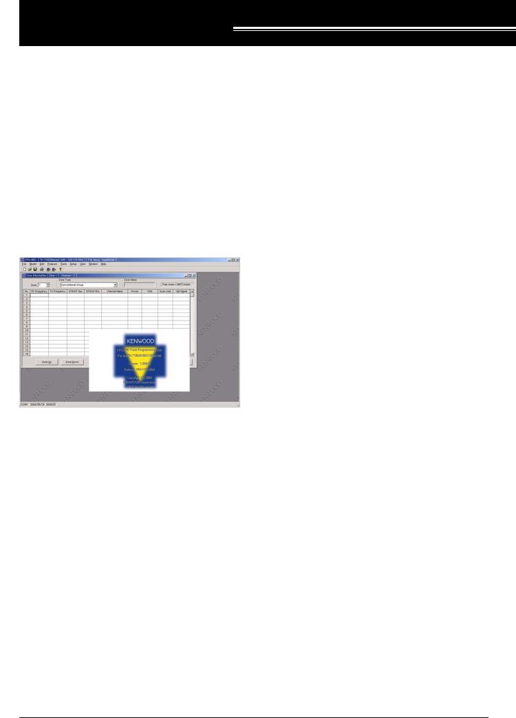
Figure 2-1 Starting Screen of the KPG-89D
The Main window of the KPG-89D appears.
The splash logo appears in the center of the screen for a while and it automatically disappears. You can also make the logo disappear by pressing any key on the keyboard or clicking a mouse button.
Select “File” > “Exit” to exit the KPG-89D.
2.2Initializing the Window
Select the transceiver model to configure. (Refer to 5 Model Menu.)
Model name, model type, frequency bandwidth, and data file name appear on the title bar located on the top of the window. (Refer to 3.1.1 Title Bar.)
2.3Writing the Configuration Data to the Transceiver
Follow the procedures below to write the configuration data to the transceiver.
1.Enter all necessary data.
Select the item to configure in the Edit menu and enter data in the window. (Refer to 6 Edit Menu.)
2.Writing data to the transceiver
Select “Program” > “Write Data to the Transceiver”. (Refer to 7 Program Menu.)
2.4Modifying the Configuration Data
Follow the procedures below to modify the configuration data.
1.Read the configuration data from the transceiver.
Select “Program” > “Read Data from the Transceiver”. (Refer to 7 Program Menu.)
2.Edit the data on the PC.
Select the item to configure in the Edit menu and enter data in the window. (Refer to 6 Edit Menu.)
3.Write the updated data to the transceiver
Select “Program” > “Write Data to the Transceiver”. (Refer to 7 Program Menu.)
2.5Editing the Configuration Data and Writing to the Transceiver
Follow the procedures below to edit the configuration data and write it to the transceiver.
1.Open the configuration data stored in the hard disk drive or other storage devices.
Select “File” > “Open” to open the configuration data. (Refer to 4 File Menu.)
2.Editing the configuration data using the KPG-89D
Select the item to configure in the Edit menu and enter data in the window. (Refer to 6 Edit Menu.)
3.Writing the configuration data to the Transceiver
Select “Program” > “Write Data to the Transceiver”. (Refer to 7 Program Menu.)
Version: 1.11 |
Field Programming Reference |
3 |

2 BASIC OPERATION
2.6Displaying Help
Click “Help” to open the KPG-89D HTML Help window. Press [F1] to display the Help Topics of the selected item. (Refer to 12 Help Menu.)
4 |
Field Programming Reference |
Version: 1.11 |
3 MENU DESCRPTION
3.1Main Window
The title bar, menu bar, and tool bar appear on the top of this window. The status bar appears in the lower part of this window.
Figure 3-4 Menu Bar
(When the Window menu is not displayed.)
Figure 3-1 Main Window
3.1.1Title Bar
The title bar shows the model name, the frequency range, and the configuration data file name. (Refer to 5 Model Menu.)
Figure 3-2 Title Bar
3.1.2Menu Bar
The Menu bar allows you to configure the functions of the transceiver using the KPG-89D. Click the menu title to open the pulldown list. The menu commands stored in the menu appears. (Refer to 3.2 Menu Command Description.)
Note: The Window menu appears on the menu bar only when the function is selected in the Edit menu and the window of the function is displayed.
Figure 3-3 Menu Bar
(When the Window menu is displayed.)
3.1.3Toolbar
Frequently used icons are shown on the Toolbar. Click the “Toolbar” icon to execute the function.
Figure 3-5 Toolbar
Note:
!You can display or hide the Toolbar by selecting “View” > “Toolbar”. (Refer to 10.2 Toolbar.)
!You can drag-and-drop the Toolbar to any desired position.
Table 3-1 Descriptions of the Buttons on the Toolbar
Button |
Function |
|
|
|
|
|
|
|
|
This icon is for the New function in the File |
|
|
menu. |
|
|
This function allows you to clear the current |
|
New |
configuration data and create the new |
|
configuration data. (Refer to 4.1 New.) |
||
|
||
|
|
|
|
This icon is for the Open function in the File |
|
|
menu. |
|
|
This function allows you to open the |
|
|
configuration data stored in the hard disk or |
|
Open |
other external storage devices. (Refer to |
|
|
4.2 Open.) |
|
|
|
|
|
This icon is for the Save function in the File |
|
|
menu. |
|
|
This function allows you to save the current |
|
Save |
configuration data to the hard disk or other |
|
external storage devices. (Refer to 4.3 |
||
|
Save.) |
|
|
|
|
|
This icon is for the Print function in the File |
|
|
menu. |
|
This function allows you to print out the |
||
configuration data. (Refer to 4.5 Print.) |
||
|
|
|
|
This icon is for the Read Data from the |
|
|
Transceiver function in the File menu. |
|
|
This function allows you to read the |
|
Read |
configuration data from the transceiver by |
|
using the KPG-89D. (Refer to 7.1 Read |
||
|
Data from the Transceiver.) |
|
|
|
|
|
This icon is for the Write Data to the |
|
|
Transceiver function in the File menu. |
|
|
This function allows you to write the data to |
|
Write |
the transceiver using the KPG-89D. (Refer |
|
|
to 7.2 Write Data to the Transceiver.) |
|
|
|
|
|
This icon is for the About KPG-89D function |
|
|
in the File menu. (Refer to 12.2 About KPG- |
|
About KPG-89D |
89D.) |
|
|
|
Version: 1.11 |
Field Programming Reference |
5 |
3 MENU DESCRPTION
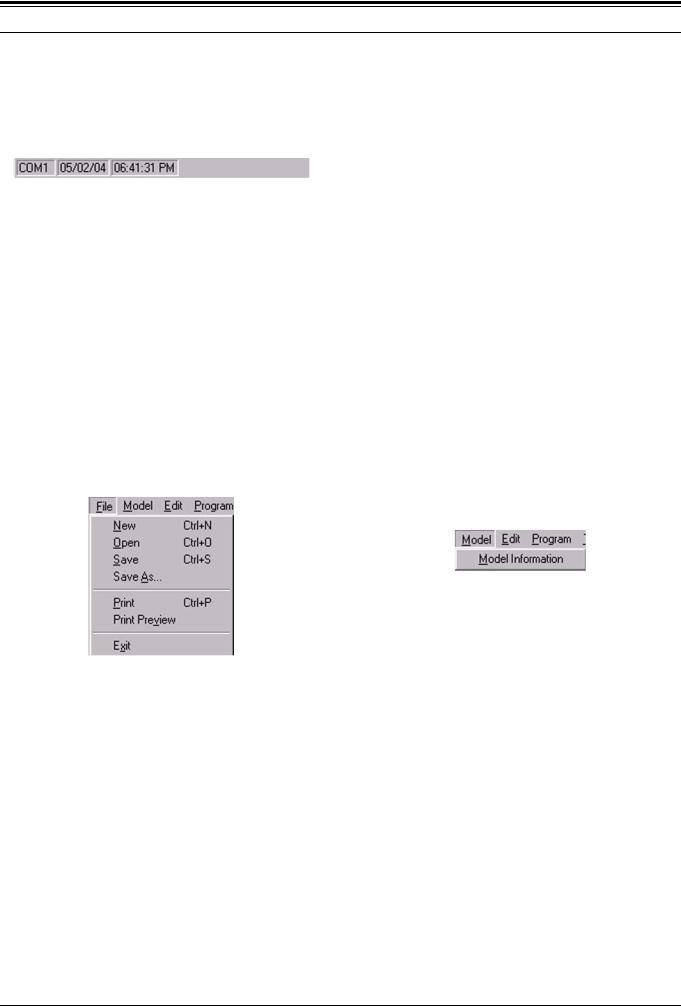
3.1.4Status Bar
The status bar shows the serial communication port used to perform the data communication between the KPG89D and the transceiver, and the current data and the date.
Figure 3-6 Status Bar
Note:
!You can display or hide the status bar by selecting “View” > “Status Bar”. (Refer to 10.3 Status Bar.)
!Double-click “COM” to open the COM port window.
3.2Menu Command Description
Following are the descriptions of the Menu Commands.
3.2.1File Menu
Figure 3-7 File Menu
Table 3-2 Function list of the File Menu
Function |
Description |
|
|
|
|
|
|
|
|
This function allows you to clear the current |
|
New |
configuration data and create the new |
|
|
configuration data. (Refer to 4.1 New.) |
|
|
|
|
|
This function allows you to open the |
|
Open |
configuration data stored in the hard disk or |
|
other external storage devices. (Refer to |
||
|
||
|
4.2 Open.) |
|
|
|
|
|
This function allows you to save the current |
|
Save |
configuration data to the hard disk or other |
|
external storage devices. (Refer to 4.3 |
||
|
||
|
Save.) |
|
|
|
|
|
This function allows you to name the current |
|
Save As |
configuration data and save it to the hard |
|
disk or other external storage devices. |
||
|
||
|
(Refer to 4.4 Save As.) |
|
|
|
|
This function allows you to print out the |
||
configuration data. (Refer to 4.5 Print.) |
||
|
||
|
|
|
|
This function allows you to view the print |
|
Print Preview |
image of the configuration data. (Refer to |
|
|
4.6 Print Preview.) |
|
|
|
|
Exit |
This function allows you to exit the KPG- |
|
89D program. (Refer to 4.7 Exit.) |
||
|
||
|
|
3.2.2Model Menu
Figure 3-8 Model Menu
Table 3-3 Function List of the Model Menu
Function |
Description |
|
|
|
|
|
|
|
Model |
This function allows you to configure the |
|
model name and the frequency. (Refer to |
||
Information |
||
5.1 Model Information.) |
||
|
||
|
|
6 |
Field Programming Reference |
Version: 1.11 |
3 MENU DESCRPTION
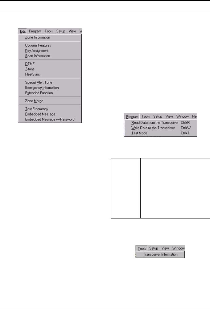
3.2.3Edit Menu
Figure 3-9 Edit Menu
Table 3-4 Function List of the Edit Menu
Function |
Description |
|
|
|
|
|
|
|
|
This function allows you to configure the |
|
Zone Information |
Zone data. (Refer to 6.1 Zone Information |
|
|
Window.) |
|
|
|
|
Optional |
This function allows you to configure the |
|
transceiver’s functions. (Refer to 6.7 |
||
Features |
||
Optional Features Window.) |
||
|
||
|
|
|
|
This function allows you to assign functions |
|
Key Assignment |
to the PF keys. (Refer to 6.8 Key |
|
|
Assignment Window.) |
|
|
|
|
|
This function allows you to configure the |
|
Scan Information |
Scan function parameters. (Refer to 6.9 |
|
|
Scan Information Window.) |
|
|
|
|
|
This function allows you to configure the |
|
DTMF |
DTMF parameters. (Refer to 6.10 DTMF |
|
|
Window.) |
|
|
|
|
|
This function allows you to configure the 2- |
|
2-tone |
tone signaling parameters. (Refer to 6.11 2- |
|
|
tone Window.) |
|
|
|
|
|
This function allows you to configure the |
|
FleetSync |
FleetSync function. (Refer to 6.12 |
|
|
FleetSync Window.) |
|
|
|
|
Special Alert |
This function allows you to configure the |
|
Special Alert Tone parameters. (Refer to |
||
Tone |
||
6.13 Special Alert Tone Window.) |
||
|
||
|
|
|
Emergency |
This function allows you to configure the |
|
Emergency Mode parameters. (Refer to |
||
Information |
||
6.14 Emergency Information Window.) |
||
|
||
|
|
|
|
This function allows you to configure the |
|
Extended |
optional board, the Auxiliary ports, and the |
|
Function |
Modulation Line parameters. (Refer to 6.15 |
|
|
Extended Function Window.) |
|
|
|
Function |
Description |
|
|
|
|
|
|
|
Zone Merge |
You can use the Zone Merge function. |
|
(Refer to 6.16 Zone Merge Window.) |
||
|
||
|
|
|
|
This function allows you to configure the |
|
Test Frequency |
Test Frequency (Test Channel) used in Test |
|
|
Mode. (Refer to 6.17 Test Frequency.) |
|
|
|
|
|
This function allows you to configure the |
|
Embedded |
characters to be stored in the transceiver. |
|
Message |
(Refer to 6.18 Embedded Message |
|
|
Window.) |
|
|
|
|
|
This function allows you to configure the |
|
Embedded |
characters to be stored in the transceiver |
|
Message w/ |
and the password to protect the stored |
|
Password |
characters. (Refer to 6.19 Embedded |
|
|
Message w/Password.) |
|
|
|
3.2.4Program Menu
Figure 3-10 Program Menu
Table 3-5 Function List of the Program Menu
Function |
Description |
|
|
|
This function allows you to read the |
Read Data from |
configuration data from the transceiver by |
the Transceiver |
using the KPG-89D. (Refer to 7.1 Read |
|
Data from the Transceiver.) |
|
|
|
This function allows you to write the |
Write Data to the |
configuration data to the transceiver using |
Transceiver |
the KPG-89D. (Refer to 7.2 Write Data to |
|
the Transceiver.) |
|
|
|
This function allows you to test or adjust the |
Test Mode |
transceiver using the KPG-89D. (Refer to |
7.3Test Mode.)
3.2.5Tools Menu
|
Figure 3-11 |
Tools Menu |
|
Table 3-6 Function List of the Tools Menu |
|||
|
|
|
|
Function |
|
Description |
|
|
|
||
|
|
||
Transceiver |
This function allows you to read the data |
||
from the transceiver. (Refer to 8.1 |
|||
Information |
|||
Transceiver Information.) |
|||
|
|||
|
|
|
|
Version: 1.11 |
Field Programming Reference |
7 |
3 MENU DESCRPTION
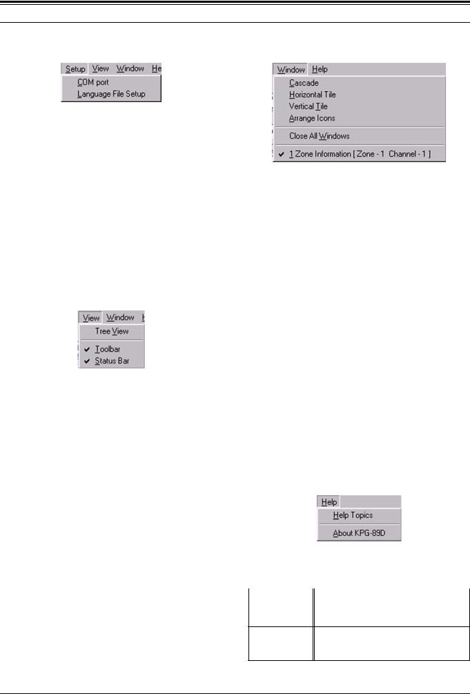
3.2.6 Setup Menu 3.2.8 Window Menu
Figure 3-12 Setup Menu
Table 3-7 Function List of the Setup Menu
Function |
Description |
|
|
|
|
|
|
|
|
You can assign the serial communication |
|
|
port used to make the data communication |
|
COM port |
between the KPG-89D and the transceiver |
|
|
to the serial communication port of the PC. |
|
|
(Refer to 9.1 COM port.) |
|
|
|
|
Language File |
You can select the language used in the |
|
KPG-89D. (Refer to 9.2 Language File |
||
Setup |
||
Setup.) |
||
|
||
|
|
3.2.7View Menu
Figure 3-13 View Menu
Table 3-8 Function List of the View Menu
Function |
Description |
|
|
|
|
|
|
|
|
This function allows you to view the contents |
|
Tree View |
of the Edit menu in the list format. (Refer to |
|
|
10.1 Tree View.) |
|
|
|
|
Toolbar |
This function allows you to display/hide the |
|
Toolbar. (Refer to 10.2 Toolbar.) |
||
|
||
|
|
|
Status Bar |
This function allows you to display/hide the |
|
Status bar. (Refer to 10.3 Status Bar.) |
||
|
||
|
|
Figure 3-14 Window Menu
Table 3-9 Function List of the Window Menu
Function |
Description |
|
|
|
|
|
|
|
|
This function allows you to rearrange the |
|
Cascade |
opened windows in an overlapped fashion |
|
|
(cascade format). (Refer to 11.1 Cascade.) |
|
|
|
|
|
This function allows you to rearrange the |
|
Horizontal Tile |
opened windows in the horizontal tiles |
|
|
fashion. (Refer to 11.2 Horizontal Tile.) |
|
|
|
|
|
This function allows you to rearrange the |
|
Vertical Tile |
opened windows in the vertical tiles fashion. |
|
|
(Refer to 11.3 Vertical Tile.) |
|
|
|
|
|
This function allows you to rearrange the |
|
Arrange Icons |
icons of the minimized windows. (Refer to |
|
|
11.4 Arrange Icons.) |
|
|
|
|
Close All |
This function allows you to close all the |
|
opened windows. (Refer to 11.5 Close All |
||
Windows |
||
Windows.) |
||
|
||
|
|
|
|
This function allows you to list all opened |
|
Opened Window |
windows. When clicking the title of the |
|
List |
window, the selected window appears. |
|
|
(Refer to 11.6 Opened Window List.) |
|
|
|
3.2.9Help Menu
|
Figure 3-15 |
Help Menu |
|
Table 3-10 Function List of the Help Menu |
|||
|
|
|
|
Function |
|
Description |
|
|
|
||
|
|
||
Help Topics |
This function allows you to search for the |
||
help topics. (Refer to 12.1 Help Topics.) |
|||
|
|||
This function allows you to view the About KPG-89D information about the KPG-89D. (Refer to
12.2 About KPG-89D.)
8 |
Field Programming Reference |
Version: 1.11 |

3 MENU DESCRPTION
3.3Shortcut Keys
You can configure the following shortcut keys using the KPG-89D.
3.3.1Menu Bar Operation
Table 3-11 Shortcut Keys Used in the Menu Bar
Key Name |
Function |
|
|
|
|
|
|
|
|
You can use the Menu Bar. |
|
[Alt] |
The File menu opens in the same way as |
|
[F10] |
the cursor is placed on the “File” in the menu |
|
|
bar. |
|
|
|
|
[←] |
You can select the menu title using [←] and |
|
[→] after selecting the menu bar using [Alt] |
||
[→] |
||
or [F10]. |
||
|
||
|
|
|
[↑] |
You can open the selected menu and select |
|
[↓] |
the function to be executed. |
|
|
|
|
|
Press [Enter] while selecting the menu title |
|
[Enter] |
to open the menu. |
|
Press [Enter] while the menu is opened to |
||
|
||
|
execute the selected function. |
|
|
|
3.3.2File Menu Operation
Table 3-12 Shortcut Keys used in the File Menu
Key Name |
Function |
|
|
|
|
[Ctrl] + [N] |
Select File > New. (Refer to 4.1 New.) |
|
|
[Ctrl] + [O] |
Select File > Open. (Refer to 4.2 Open.) |
|
|
[Ctrl] + [S] |
Select File > Save. (Refer to 4.3 Save.) |
|
|
[Ctrl] + [P] |
Select File > Print. (Refer to 4.5 Print.) |
|
|
3.3.3Zone Information (Conventional Group) Window
Table 3-13 Zone Information (Conventional Group)
Window Shortcut Keys
Key Name |
Function |
|
|
|
|
|
|
|
[F7] |
The Zone number can be increased in steps of |
|
1. |
||
|
||
|
|
|
[F8] |
The Zone number can be decreased in steps of |
|
1. |
||
|
||
|
|
|
|
You can display the Zone Edit (Conventional |
|
[F9] |
Group) window. (Refer to 6.2 Zone Edit |
|
|
Window (Conventional Group).) |
|
|
|
|
[F11] |
You can display the Channel Edit window. |
|
(Refer to 6.3 Channel Edit Window.) |
||
|
||
|
|
|
|
You can display the Channel Copy window. |
|
[Shift] + [F3] |
You can also copy the configured channel data |
|
to the specified channel. (Refer to 6.3.19 |
||
|
Channel Copy ([Shift] + [F3]).) |
|
|
|
|
|
You can display the Frequency Copy window. |
|
[Shift] + [F4] |
You can copy the Receive Frequency data to |
|
the Transmission Frequency data. (Refer to |
||
|
6.3.20 Frequency Copy ([Shift] + [F4]).) |
|
|
|
|
|
You can display the QT/DQT Copy window. |
|
|
You can copy the QT/DQT Decode of the |
|
[Shift] + [F5] |
selected channel to the “QT/DQT Encode” data. |
|
|
(Refer to 6.3.20 Frequency Copy ([Shift] + |
|
|
[F4]).) |
|
|
|
|
|
You can display the Channel Jump window. |
|
[Shift] + [F7] |
You can jump to the specified channel. (Refer |
|
|
to 6.3.21 Channel Jump.) |
|
|
|
3.3.4Zone Information (Trunking System) Window
Table 3-14 Zone Information (Trunking System) Window
Shortcut Keys
Key Name |
Function |
|
|
|
|
|
|
|
|
You can display the Repeater Information |
|
[F6] |
window. (Refer to 6.4 Repeater Information |
|
|
Window.) |
|
|
|
|
[F7] |
The Zone number can be increased in steps of |
|
1. |
||
|
||
|
|
|
[F8] |
The Zone number can be decreased in steps of |
|
1. |
||
|
||
|
|
|
|
You can display the Zone Edit (Trunking |
|
[F9] |
system) window. (Refer to 6.5 Zone Edit |
|
|
Window.) |
|
|
|
|
[F11] |
You can display the GID Edit window. (Refer to |
|
6.6 GID Edit Window.) |
||
|
||
|
|
|
|
You can display the GID Copy window. You can |
|
[Shift] + [F3] |
copy the selected GID data to the specified GID. |
|
|
(Refer to 6.6.18 GID Copy ([Shift] + [F3]).) |
|
|
|
Version: 1.11 |
Field Programming Reference |
9 |
3 MENU DESCRPTION
Key Name |
Function |
You can display the GID Jump window. You [Shift] + [F7] can jump to the specified GID. (Refer to 6.6.19
GID Jump.)
3.3.5Program Menu
Table 3-15 Shortcut Keys used in the Program Menu
Key Name |
Function |
|
|
|
|
|
|
|
|
Select “Program” > “Read Data from the |
|
[Ctrl] + [R] |
Transceiver”. (Refer to 7.1 Read Data from the |
|
|
Transceiver.) |
|
|
|
|
|
Select “Program”> “Write Data to the |
|
[Ctrl] + [W] |
Transceiver”. (Refer to 7.2 Write Data to the |
|
|
Transceiver.) |
|
|
|
|
[Ctrl] + [T] |
Select “Program” > “Test Mode”. (Refer to 7.3 |
|
Test Mode.) |
||
|
||
|
|
3.3.6Help Menu
Table 3-16 Shortcut Keys used in Help Menu
Key Name |
Function |
You can display the KPG-89D HTML Help
[F1] window. The help topic for the selected operation appears when the [F1] key is
pressed. (Refer to 12 Help Menu.)
10 |
Field Programming Reference |
Version: 1.11 |
4 FILE MENU
4.1New
Select “File” > “New” to create the new data file. You can clear the current configuration data and create the new data file.
The default file name for a new file will be “kpg89d.dat”. Follow the procedures below to create a new file.
1.Select “File” > “New”.
A warning message appears.
Figure 4-1 File New
2.You can select one of the following options.
•Click “OK”.
You can delete all of the opened configuration data.
You can clear the current configuration data and create a new data file.
•Click “Cancel”.
The opened configuration data will not be deleted. No file will be created.
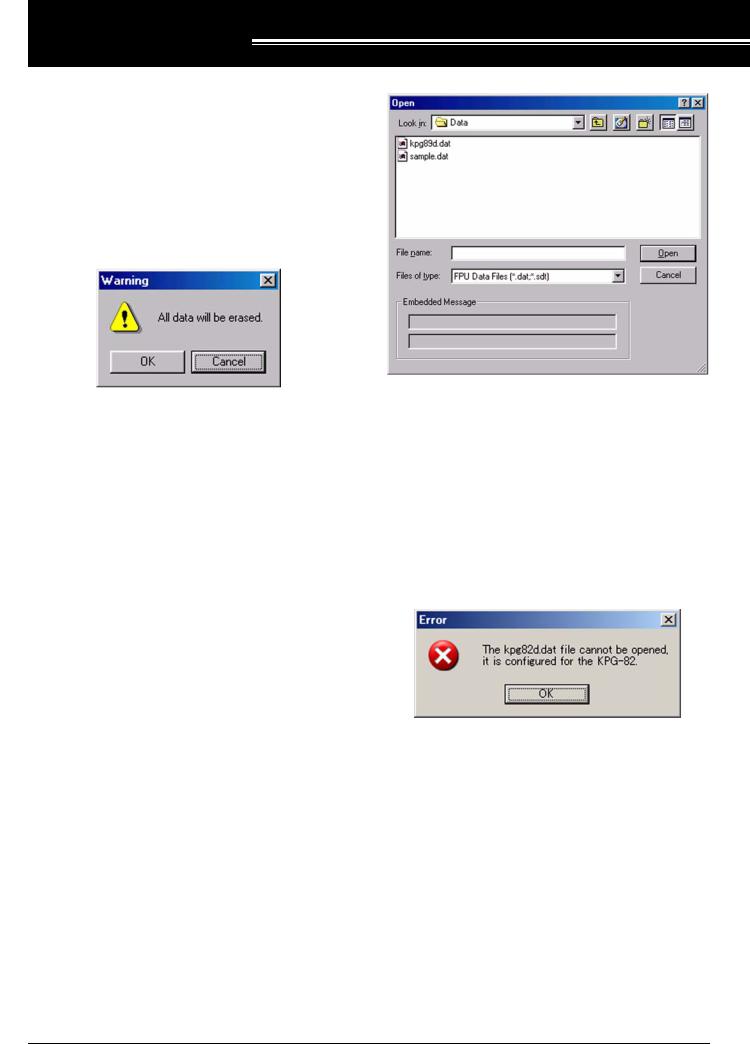
Figure 4-2 File Open
2.Select the configuration data file to open. Select a file name you want to open.
The embedded message appears if the selected file contains an embedded message. (Refer to 6.18 Embedded Message Window.)
3.Click “Open”.
You can read the file selected at the previous step using the KPG-89D.
The error message appears when the selected file contains data that is not supported by the KPG-89D.
4.2 |
Open |
|
This function allows you to open the configuration data |
|
|
file stored in the hard disk or other external storage |
|
|
devices (file extension: .dat/ .sdt). |
Figure 4-3 File Open Error Message |
|
Follow the procedures below to open the configuration data.
1. Select “File” > “Open”.
The Open window appears.
Version: 1.11 |
Field Programming Reference |
11 |

4 FILE MENU
4.3Save
This function allows you to store the current configuration data to the hard disk or other external storage devices.
Follow the procedures below to save the configuration data.
1.Select “File” > “Save”.
The configuration data is stored as a new file.
A warning message appears if a file with the same name exists in the destination folder.
Figure 4-4 File Save
2.You can select one of the following options.
•Click “OK”.
You can store the new configuration data to the storage device.
•Click “Cancel”.
This option allows you to stop saving the configuration data. The new configuration data will not be stored.
4.4Save As
This function allows you to name the current configuration data and store it to the hard disk or other external storage devices.
Follow the procedures below to name and save the configuration data.
1.Select “File” > “Save As”.
The File Type Confirmation window appears.
Figure 4-5 Save As Confirmation Window
2.Click “Data File” to store the configuration data as a data file, or Source File to store the data as a source file.
The Save As window appears.
Figure 4-6 Save As
3.Enter the file name.
You can assign a maximum of 32 characters to a file name. When assigning 33 or more characters, the following error message appears.
Figure 4-7 Save As Error Message
4.Click “Save”.
You can store the configuration data with the file name entered in the previous step.
A warning message appears if a file with the same name exists in the target folder.
Figure 4-8 Save As Warning Message
12 |
Field Programming Reference |
Version: 1.11 |
4 FILE MENU
5.You can select one of the following options.
•Click “Yes”.
You can store the new configuration data to the storage device.
•Click “Cancel”.
This option allows you to stop saving the configuration data. The current configuration data will not be stored.
4.5Print
You can print out the configuration data.
Follow the procedures print the configuration data.
1.Select “File” > “Print”.
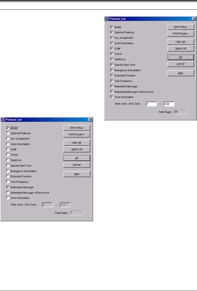
The Printout List appears and you can view the KPG89D configuration data.
Figure 4-9 Printout List 1
2.Confirm the checkbox of the configuration data item that you want to print.
Figure 4-10 Printout List 2
Note:
!The Model checkbox and the Embedded Message checkbox are checked as default configuration.
!The Start Zone edit box and the End Zone edit box appear when checking the Zone Information checkbox
3.Click “OK”.
You can print out the KENWOOD KPG-89D Transceiver Programming Information. (Refer to 4.6 Print Preview.)
4.5.1Print List Item
" Model
You can configure the “Model Information” parameters to print. (Refer to 5.1 Model Information.)
|
Check (Enable) |
The parameters can be |
|
|
printed. |
||
Range |
|
||
|
|
||
Uncheck (Disable) |
The parameters will not |
||
|
|||
|
be printed. |
||
|
|
||
|
|
|
|
Default |
Checked (Enabled) |
|
|
|
|
|
Version: 1.11 |
Field Programming Reference |
13 |

4 FILE MENU
" Optional Features " FleetSync
You can configure the Optional Features parameters to print. (Refer to 6.7 Optional Features Window.)
You can configure the FleetSync parameters to print. (Refer to 6.12 FleetSync Window.)
|
Check (Enable) |
The parameters can be |
|
|
printed. |
||
Range |
|
||
|
|
||
Uncheck (Disable) |
The parameters will not |
||
|
|||
|
be printed. |
||
|
|
||
|
|
|
|
Default |
Unchecked (Disabled) |
|
|
|
|
|
|
Check (Enable) |
The parameters can be |
|
|
printed. |
||
Range |
|
||
|
|
||
Uncheck (Disable) |
The parameters will not |
||
|
|||
|
be printed. |
||
|
|
||
|
|
|
|
Default |
Unchecked (Disabled) |
|
|
|
|
|
" Key Assignment
You can configure the Key Assignment parameters to print. (Refer to 6.8 Key Assignment Window.)
|
Check (Enable) |
The parameters can be |
|
|
printed. |
||
Range |
|
||
|
|
||
Uncheck (Disable) |
The parameters will not |
||
|
|||
|
be printed. |
||
|
|
||
|
|
|
|
Default |
Unchecked (Disabled) |
|
|
|
|
|
" Special Alert Tone
You can configure the Special Alert Tone parameters to print. (Refer to 6.13 Special Alert Tone Window.)
|
Check (Enable) |
The parameters can be |
|
|
printed. |
||
Range |
|
||
|
|
||
Uncheck (Disable) |
The parameters will not |
||
|
|||
|
be printed. |
||
|
|
||
|
|
|
|
Default |
Unchecked (Disabled) |
|
|
|
|
|
" Scan Information
You can configure the Scan Information parameters to print. (Refer to 6.9 Scan Information Window.)
|
Check (Enable) |
The parameters can be |
|
|
printed. |
||
Range |
|
||
|
|
||
Uncheck (Disable) |
The parameters will not |
||
|
|||
|
be printed. |
||
|
|
||
|
|
|
|
Default |
Unchecked (Disabled) |
|
|
|
|
|
" DTMF
You can configure the DTMF parameters to print. (Refer to 6.10 DTMF Window.)
|
Check (Enable) |
The parameters can be |
|
|
printed. |
||
Range |
|
||
|
|
||
Uncheck (Disable) |
The parameters will not |
||
|
|||
|
be printed. |
||
|
|
||
|
|
|
|
Default |
Unchecked (Disabled) |
|
|
|
|
|
" 2-tone
You can configure the 2-tone parameters to print. (Refer to 6.11 2-tone Window.)
|
Check (Enable) |
The parameters can be |
|
|
printed. |
||
Range |
|
||
|
|
||
Uncheck (Disable) |
The parameters will not |
||
|
|||
|
be printed. |
||
|
|
||
|
|
|
|
Default |
Unchecked (Disabled) |
|
|
|
|
|
" Emergency Information
You can configure the Emergency Information
parameters to print. (Refer to 6.14 Emergency
Information Window.)
|
Check (Enable) |
The parameters can be |
|
|
printed. |
||
Range |
|
||
|
|
||
Uncheck (Disable) |
The parameters will not |
||
|
|||
|
be printed. |
||
|
|
||
|
|
|
|
Default |
Unchecked (Disabled) |
|
|
|
|
|
" Extended Function
You can configure the Extended Function parameters to print. (Refer to 6.15 Extended Function Window.)
|
Check (Enable) |
The parameters can be |
|
|
printed. |
||
Range |
|
||
|
|
||
Uncheck (Disable) |
The parameters will not |
||
|
|||
|
be printed. |
||
|
|
||
|
|
|
|
Default |
Unchecked (Disabled) |
|
|
|
|
|
" Test Frequency
You can configure the Test Frequency parameters to print. (Refer to 6.17 Test Frequency.)
|
Check (Enable) |
The parameters can be |
|
|
printed. |
||
Range |
|
||
|
|
||
Uncheck (Disable) |
The parameters will not |
||
|
|||
|
be printed. |
||
|
|
||
|
|
|
|
Default |
Unchecked (Disabled) |
|
|
|
|
|
14 |
Field Programming Reference |
Version: 1.11 |
4 FILE MENU
" Embedded Message
You can configure the Embedded Message
parameters to print. (Refer to 6.18 Embedded
Message Window.)
|
Check (Enable) |
The parameters can be |
|
|
printed. |
||
Range |
|
||
|
|
||
Uncheck (Disable) |
The parameters will not |
||
|
|||
|
be printed. |
||
|
|
||
|
|
|
|
Default |
Checked (Enabled) |
|
|
|
|
|
" Embedded Message w/Password
You can configure the Embedded Message w/ Password parameters to print. (Refer to 6.19 Embedded Message w/Password.)
|
Check (Enable) |
The parameters can be |
|
|
printed. |
||
Range |
|
||
|
|
||
Uncheck (Disable) |
The parameters will not |
||
|
|||
|
be printed. |
||
|
|
||
|
|
|
|
Default |
Unchecked (Disabled) |
|
|
|
|
|
" Zone Information
You can configure the Zone Information parameters to print. (Refer to 6.1 Zone Information Window.)
|
Check (Enable) |
The parameters can be |
|
|
printed. |
||
Range |
|
||
|
|
||
Uncheck (Disable) |
The parameters will not |
||
|
|||
|
be printed. |
||
|
|
||
|
|
|
|
Default |
Unchecked (Disabled) |
|
|
|
|
|
" Start Zone - End Zone
You can configure the start zone and the end zone only when the Channel Information checkbox is checked.
You can select the channel to print from the channels 1 to 128.
Note: The value of the Start Channel must be lower than the End Channel value. The End Channel will be equal to the Start Channel if you enter the higher value in the Start Channel than the End Channel.
Range |
Start Zone |
End Zone |
|
|
|
||
1 - 128 |
1 - 128 |
||
|
|||
|
|
|
|
Default |
1 |
128 |
|
|
|
|
" Total Pages
The total number of pages appears.
" Print Preview Button
Click “Print Preview” to display the Print Preview window. (Refer to 4.6 Print Preview.)
" Clear All Button
Click “Clear All” to uncheck all checkboxes.
" Select All Button
Click “Select All” to check all checkboxes.
" OK Button
Click “OK” to print the checked items.
" Cancel Button
Click “Cancel” to close the Printout List window without printing any parameters.
" Help Button
Click “Help” to display the KPG-89D HTML Help window. The help topics for Print appear. (Refer to 12 Help Menu.)
" Print Setup Button
Click “Print Setup” to display the Print Setup window. You can configure the printer used to print out the configuration data, the paper size, and the paper rotation.
Version: 1.11 |
Field Programming Reference |
15 |
4 FILE MENU
4.6 Print Preview " Next Page/ Prev Page Button
You can view the print image after selecting items to be printed in the Print Out List.
Follow the procedures to preview the print image.
1.You can select one of the following options.
•Select “File” > “Print Preview”.
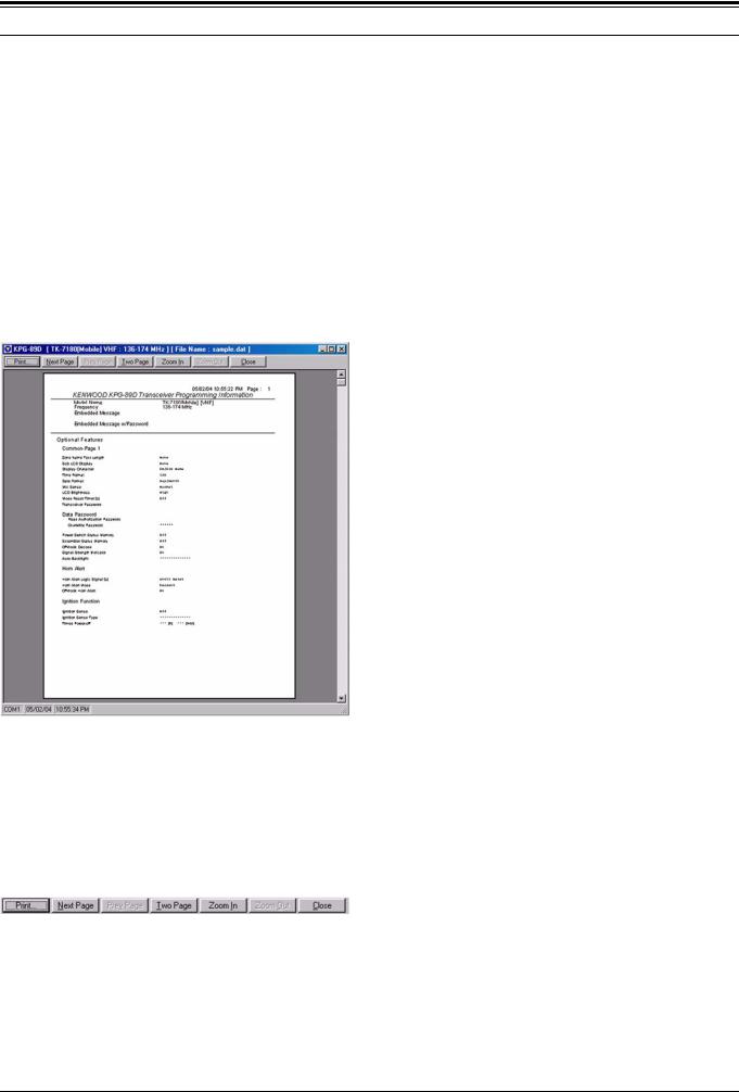
The Printout Preview window appears and the print image will be displayed.
•Click “Print Preview” in the Printout List window. (Refer to 4.5.1 Print List Item.)
The Printout Preview window appears and the print image of the items selected in the Print List will be displayed.
Figure 4-11 Print Preview
Click “Next Page” to view the next page of the current print image.
Click “Prev Page” to view the previous page of the current print image.
Note:
!You can click “Next Page” only when there are more than one page(s).
!You can click “Prev Page” only when there are preceding page(s).
"Two Page/ One Page Button
Click “Two Page” to display two pages at the same time.
Click “One Page” to display only one pages at the same time.
Note:
!The “Two Page” button appears when the layout of the print image is “One Page”.
!The “One Page” button appears when the layout of the print image is “Two Page”.
!The two page display is disabled when clicking “Zoom In” while the layout of the print image is two page. When clicking “Zoom Out”, the layout of the print image returns to Two Page.
"Zoom In/ Zoom Out Button
Click “Zoom In” to enlarge the print image. Click “Zoom Out” to zoom out the print image.
Note:
!You can click “Zoom In” only when the print image can be enlarged.
!You can click “Zoom Out” only when the print image can be zoomed out.
!You can enlarge the print image when the magnifying glass icon appears on the image. You can zoom out the print image when the cursor returns to normal.
4.6.1Toolbar in the Print Preview
You can switch the display and move to the other page by clicking the buttons on the toolbar located on the top of the window.
Figure 4-12 Print Preview Toolbar
" Print Button
Click “Print” to display the Print List window. (Refer to 4.5.1 Print List Item.)
" Close Button
Click “Close” to close the Print Preview window and return to the main window or the Print Out List window.
16 |
Field Programming Reference |
Version: 1.11 |

4 FILE MENU
4.7Exit
This function allows you to exit the KPG-89D program.
Follow the procedures to exit the KPG-89D.
1.Select “File” > “Exit”.
The confirmation dialog box appears to exit the KPG89D program.
Figure 4-13 File Exit 1
2.You can select one of the following options.
•Click “No”.
Close the confirmation dialog box. In this case, you cannot exit the KPG-89D program.
•Click “Yes”.
You can immediately exit the KPG-89D program when the configuration data has not been modified or already stored. The confirmation dialog box appears to ask you to store the configuration data if you have modified the configuration data.
Figure 4-14 File Exit 2
3.You can select one of the following options.
•Click “Cancel”.
Close the confirmation dialog box. In this case, you cannot exit the KPG-89D program.
•Click “No”.
You can exit the KPG-89D program without storing the configuration data to the storage device.
•Click “Yes”.
The Save As window appears. (Refer to 4.4 Save As.)
You can exit the KPG-89D program after storing the configuration data to the storage device.
Version: 1.11 |
Field Programming Reference |
17 |

5 MODEL MENU
5.1Model Information
You can configure the transceiver’s model type and frequency in the Model Information window.
!Click “OK” to delete all configured data and create a new data with the selected Model Type and the transmit/receive frequency. Click “Cancel” to return to the Model Information window without changing the model type and the transmit/ receive frequency.
Figure 5-1 Model Information Window
Note:
!The following warning messages appear when clicking “OK”.
•The frequency can be changed without changing the model name (TK-2180/ 3180 and TK-7180/ 8180).
Figure 5-2 Model Information Warning Message 1
•The Model Name (TK-2180/ 3180 and TK-7180/ 8180) is changed without changing the frequency.
Figure 5-3 Model Information Warning Message 2
•Both of the Model Name (TK-2180/ 3180 and TK-7180/ 8180) and the frequency are changed.
5.1.1Model Name
This function allows you to select the model name from the pulldown menu.
|
• TK-2180 [Portable] |
||
Range |
• TK-3180 |
[Portable] |
|
• TK-7180 |
[Mobile] |
||
|
|||
|
• TK-8180 |
[Mobile] |
|
|
|
||
Default |
TK-7180 [Mobile] |
||
|
|
|
|
5.1.2Frequency
You can configure the frequency bandwidth to transmit/ receive. You can select the frequency bandwidth according to the model type using the pulldown menu.
Model |
Market |
Transmit/ Receive |
Default |
|
Code |
Frequency [MHz] |
|||
|
|
|||
|
|
|
|
|
|
|
|
|
|
TK-2180 |
K |
136 - 174 |
136 -174 |
|
|
|
|
|
|
TK-3180 |
K |
450 - 520 |
450 - 520 |
|
400 - 470 |
||||
|
|
|
||
|
|
|
|
|
TK-7180 |
K |
136 - 174 |
136 - 174 |
|
|
|
|
|
|
TK-8180 |
K |
450 - 520 |
450 - 520 |
|
400 - 470 *1 |
||||
|
|
|
||
*1 Supports the updated version |
|
|||
Figure 5-4 Model Information Warning Message 3
18 |
Field Programming Reference |
Version: 1.11 |

6 EDIT MENU
6.1Zone Information Window
In the Zone Information window, configure the zone data to be used when the transceiver is transmitting and receiving.
A maximum of 128 zones in the Conventional Group/ Trunking sytem can be configured to the transceiver.
A maximum of 512 CH/GIDs can be configured to the transceiver. (Refer to 6.3 Channel Edit Window.)
6.1.1Common to Conventional Group/Trunking System
Figure 6-1 Zone Information Window
" Zone
Configure the Zone number to be configured. Enter a value directly in the edit box or click the spin button to configure.
Range 1 - 128
Default 1
" Zone Type
Configure the Zone Type. Select the Zone Type from the pulldown menu.
Range Conventional Group/ Trunking System
Default Conventional Group
" Zone Name
Configure the Zone Name. Enter the Zone Name directly in the edit box to configure the Zone Name.
Range |
A maximum of 12 alphanumeric characters |
|
|
|
|
Available |
(space) ! “ # $ % & ’ ( ) * + , - . / 0 1 2 3 4 5 6 7 8 |
|
9 : ; < = > ? @ [ \ ] ^ ` A B C D E F G H I J K L |
||
Characters |
M N O P Q R S T U V W X Y Z a b c d e f g h i j |
|
|
k l m n o p q r s t u v w x y z { | } ~ |
|
|
|
|
Default |
**1 - 128 (The Zone number is automatically |
|
entered.) |
||
|
||
|
|
" Free
Displays the remaining amount of memory that can be used for the Zone Information window.
" Zone Up/Zone Down Button
Click “Zone Up” to move up the Zone number. Click “Zone Down” to move down the Zone number.
" Close Button
Click “Close” to close the Zone Information window.
" Help Button
Click “Help” to open the KPG-89D HTML Help window. Help and topics about Zone Information are displayed. (Refer to 12 Help Menu.)
6.1.2Conventional Group
Figure 6-2 Zone Information Window (Conventional Group)
" Receive Frequency
Configure the frequency to be used when the transceiver receives. Enter the frequency directly in the edit box to configure the frequency.
|
TK-2180/ 7180 |
136 - 174 MHz |
Range |
|
|
TK-3180/ 8180 |
450 - 520 MHz |
|
|
400 - 470 MHz |
|
|
|
|
|
|
|
Default |
Blank |
|
|
|
|
Note:
!Available frequency range varies depending on the transceiver model. (Refer to FUNC 1.2 Receive/Transmit Frequency.)
!A maximum of 9-digit frequency and “.” (period) can be entered.
!When a value outside of the available range is entered, a confirmation message appears, and the value is replaced with the frequency value automatically (upper limit value or lower limit value) configured at the Model Information window > Frequency.
!Other items on the same channel can be configured only when Receive Frequency value is configured to Receive Frequency.
Version: 1.11 |
Field Programming Reference |
19 |

!When Receive Frequency is deleted, other items on the same channel are also automatically deleted.
!When Receive Frequency is configured, the same value as Receive Frequency is configured to Transmit Frequency.
"Transmit Frequency
Configure the frequency to transmit. Enter the frequency directly in the edit box to configure the frequency.
|
TK-2180/ 7180 |
136 - 174 MHz |
Range |
|
|
TK-3180/ 8180 |
450 - 520 MHz |
|
|
400 - 470 MHz |
|
|
|
|
|
|
|
Default |
Blank |
|
|
|
|
Note:
!Available frequency range varies depending on the transceiver model. (Refer to FUNC 1.2 Receive/Transmit Frequency.)
!A maximum of 9-digit frequency and “.” (period) can be entered.
!When a value outside of the available range is entered, a confirmation message appears, and the value is replaced with the frequency value automatically (upper limit value or lower limit value) configured at the Model Information >
Frequency.
!Transmit Frequency can be configured only when a value is configured in the Receive Frequency edit box.
"QT/DQT Dec (Decode)
Configure the signaling for standby to be used when the transceiver is receiving. Select the QT tone or DQT code from the pulldown menu, or directly enter it in the edit box.
# When selecting from the pulldown menu:
|
QT |
67.0 - 250.3 Hz |
|
|
|
Range |
DQT (Normal) |
D023N - D754N |
|
|
|
|
DQT (Inverted) |
D023I - D754I |
|
|
|
Default |
None |
|
|
|
|
# When entering directly in the edit box:
|
QT |
67.0 - 254.1 Hz |
|
|
|
|
|
Range |
DQT (Normal) |
D000N - D777N |
|
|
|
|
|
|
DQT (Inverted) |
D000I - D777I |
|
|
|
|
|
Step |
QT |
0.1 Hz |
|
|
|
||
DQT |
1 |
||
|
|||
|
|
|
|
Default |
None |
|
|
|
|
|
Note:
!A maximum of 5-digit QT and DQT having numbers and “N”, “D”, “I” and “.” (period) can be entered.
!When only numbers and “.” (period) are entered, the entry is configured as a QT tone.
!When a text string prefixed by “D” is entered, the entry is configured as a DQT code.
!When the entire content of the edit box is deleted, None will be configured.
!When a value outside of the available range is entered, it is replaced with the upper limit value or lower limit value of the range.
!QT/DQT Dec can be configured only when a value is configured in the Receive Frequency edit box.
"QT/DQT Enc (Encode)
Configure the signaling for calling to be used when the transceiver is transmitting. Select the QT tone or DQT code from the pulldown menu, or directly enter it in the edit box.
# When selecting from the pulldown menu:
|
QT |
67.0 - 250.3 Hz |
|
|
|
Range |
DQT (Normal) |
D023N - D754N |
|
|
|
|
DQT (Inverted) |
D023I - D754I |
|
|
|
Default |
None |
|
|
|
|
# When entering directly in the edit box:
|
QT |
67.0 - 254.1 Hz |
|
|
|
|
|
Range |
DQT (Normal) |
D000N - D777N |
|
|
|
|
|
|
DQT (Inverted) |
D000I - D777I |
|
|
|
|
|
Step |
QT |
0.1 Hz |
|
|
|
||
DQT |
1 |
||
|
|||
|
|
|
|
Default |
None |
|
|
|
|
|
Note:
!A maximum of 5-digit QT and DQT having numbers and “N”, “D”, “I” and “.” (period) can be entered.
!When only numbers and “.” (period) are entered, the entry is configured as a QT tone.
!When a text string prefixed by “D” is entered, the entry is configured as a DQT code.
!When the entire content of the edit box is deleted, None will be configured.
!When a value outside of the available range is entered, it is replaced with the upper limit value or lower limit value of the range.
!QT/DQT Enc can be configured only when a value is configured in the Receive Frequency edit box.
"Channel Name
Configure the channel name of the channel to be configured. The channel name can be entered directly in the edit box to configure the channel name.
Range A maximum of 12 alphanumeric characters
(space) ! “ # $ % & ’ ( ) * + , - . / 0 1 2 3 4 5 6 7 8 9 Available : ; < = > ? @ [ \ ] ^ ` A B C D E F G H I J K L M N Characters O P Q R S T U V W X Y Z a b c d e f g h i j k l m n
o p q r s t u v w x y z { | } ~
Default |
CH nnn (The channel number is entered |
|
automatically.) |
||
|
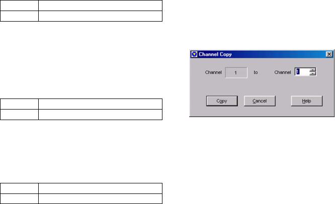
Note:
!When the entire content of the edit box is deleted, this item will be configured as a blank.
!Channel Name can be configured only when a value is configured in the Receive Frequency edit box.
"Power (Transmit Power)
Configure the transmit power of each channel. Select the desired transmit power from the pulldown menu.
Range |
High/ Low |
Default High
Note: Transmit Power can be configured only when a value is configured in the Receive Frequency and Transmit Frequency edit boxes.
" W/N (Wide/ Narrow)
Configure the channel bandwidth of each channel. Select the desired channel bandwidth from the pulldown menu.
Range Wide/ Narrow
Default Wide
Note: W/N can be configured only when a value is configured in the Receive Frequency edit box.
" Scan Add
From the pulldown menu, select whether or not the transceiver scans each channel during the scan.
Range |
Yes/ No |
Default Yes
Note: Scan Add can be configured only when a value is configured in the Receive Frequency edit box.
" Optional Signaling
Configure the Optional Signaling of each channel. Select the desired Optional Signaling from the pulldown menu.
Range |
None/ DTMF/ 2-tone 1/ 2-tone 2/ 2-tone 3/ |
|
2-tone 4/ FleetSync |
||
|
||
|
|
|
Default |
None |
|
|
|
Note: Optional Signaling can be configured only when a value is configured in the Receive Frequency edit box.
" Zone Edit Button
Click “Zone Edit” to open the Zone Edit window.
(Refer to 6.2 Zone Edit Window (Conventional
Group).)
" Channel Edit Button
Click “Channel Edit” to open the Channel Edit window. (Refer to 6.3 Channel Edit Window.)
" Channel Copy ([Shift] + [F3])
Existing channel data can be copied to other channels.
To do this, follow the procedures below:
1.Select the channel to be copied.
The channel can be selected by clicking the channel number.
2.Press [Shift] + [F3] on the keyboard. The Channel Copy window appears.
Figure 6-3 Channel Copy Window
3.Select the desired channel to copy to.
Enter a value directly in the edit box or click the spin button to configure.
4.Click “Copy”.
The configured data is copied to the copy target channel.
Note:
!This operation is possible only when data is currently configured to the copy source channel.
!Only numbers within the range 1 to 250 can be entered.
!When the entire content of the edit box is deleted, 1 will be configured.
!When a value outside of the available range is entered, it is replaced with the upper limit value or lower limit value of the range.
"Frequency Copy ([Shift] + [F4])
Data configured to Receive Frequency can be copied to Transmit Frequency of the same channel.
To do this, follow the procedures below:
Note: An error message appears when there is no data configured to a zone.
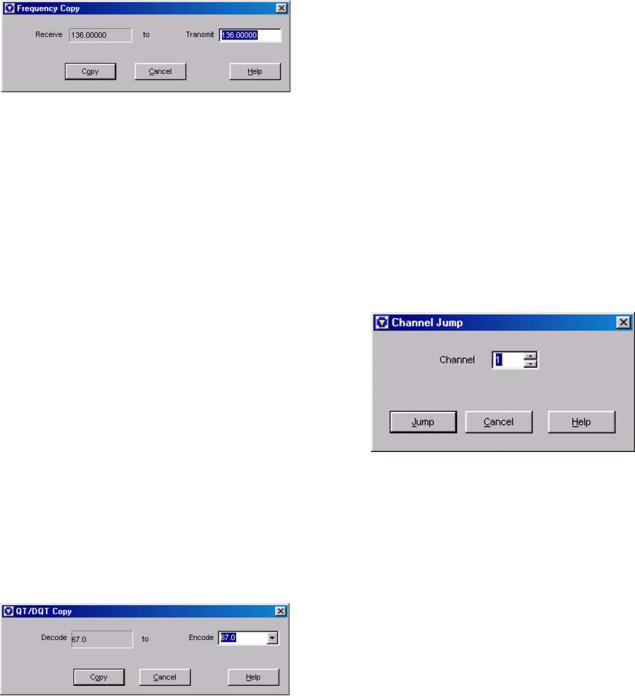
1.Select the channel to be copied.
The channel can be selected by clicking the channel number.
2.Press [Shift] + [F4] on the keyboard. The Frequency Copy window appears.
Figure 6-4 Frequency Copy Window
3.Click “Copy”.
the Receive Frequency data is copied to Transmit Frequency of the same channel.
Note:
!This operation is possible only on channels in which data is currently configured to Receive Frequency.
!Receive Frequency configuration data cannot be copied to other channels.
!When a frequency is entered directly in the Frequency Copy window, that value is configured as the frequency of Transmit Frequency. In this case, only frequencies up to 9- digit numbers and “.” (period) can be entered.
!When the entire content of the edit box is deleted, a blank will be configured.
!When a value outside of the available range is entered, it is replaced with the upper limit value or lower limit value of the range.
"QT/DQT Copy ([Shift] + [F5])
Data configured to QT/DQT Decode can be copied to QT/DQT Encode of the same channel.
To do this, follow the procedures below:
1.Select the channel to be copied.
The channel can be selected by clicking the channel number.
2.Press [Shift] + [F5] on the keyboard. The QT/DQT Copy window appears.
Figure 6-5 QT/DQT Copy Window
3.Click “Copy”.
QT/DQT Decode data is copied to QT/DQT Encode of the same channel.
Note:
!This operation is possible only on channels in which data is currently configured to QT/DQT Decode.
!QT/DQT Decode configuration data cannot be copied to other channels.
!When the QT/DQT Encode value is selected or entered directly in the QT/DQT Copy window, that value is configured as QT/DQT Encode. In this case, a maximum of 5-digit QT and DQT having numbers and “N”, “D”, “I” and “.” (period) can be entered.
!When the entire content of the edit box is deleted, None will be configured.
!When a value outside of the available range is entered, it is replaced with the upper limit value or lower limit value of the range.
"Channel Jump ([Shift] + [F7])
Specified channels can also be jumped to.
To do this, follow the procedures below:
1.Press [Shift] + [F7] on the keyboard. The Channel Jump window appears.
Figure 6-6 Channel Jump Window
2.Enter the channel number to be displayed.
Enter a value directly in the edit box or click the spin button to configure.
3.Click “Jump”.
The specified channel appears.
Note:
!Only numbers within the range 1 to 250 can be entered.
!When the entire content of the edit box is deleted, 1 will be configured.
!When a value outside of the available range is entered, it is replaced with the upper limit value or lower limit value of the range.

" Context Menu
If you select and right-click the channel number, Context Menu appears, and then operations such as copy and delete of configuration data can be performed.
|
Figure 6-7 Context Menu |
|
Table 6-1 Context Menu |
|
|
Function |
Description |
|
|
|
|
Copy |
Copies the currently selected channel data. |
|
|
Paste |
Pastes the copied channel data. |
|
|
Delete |
Deletes the currently selected channel data. |
|
|
to Clipboard |
Copies the currently selected channel data to |
|
the Clipboard as text data. |
to Clipboard |
Copies the currently selected channel data to |
(w/headings) |
the Clipboard as text data with a heading. |
|
|
6.1.3Trunking System
Figure 6-8 Zone Information Window (Trunking System)
" Encode ID
Configure the Encode ID to be used when the transceiver transmits. Enter the Encode ID number directly in the edit box to configure the Encode ID number.
Range Blank/ 1 - 250
Step 1
Default Blank
Note:
!A maximum of 3-digit numbers can be entered.
!When the entire content of the edit box is deleted, this item will be configured as a blank.
!When a value outside of the available range is entered, it is replaced with the upper limit value or lower limit value of the range.
"Decode ID
Configure the Decode ID to be used when the transceiver is receiving. Enter the Decode ID number directly in the edit box to configure the Decode ID number.
Range |
Blank/ 1 - 250 |
|
|
Step |
1 |
|
|
Default |
A value entered by Encode ID |
|
|
Note:
!A maximum of 3-digit numbers can be entered.
!When a value outside of the available range is entered, it is replaced with the upper limit value or lower limit value of the range.
!When the value of the Decode ID edit box is deleted, the other items of the same Group ID are automatically deleted.
"GID Name
Configure the Group ID name of the Group ID to be configured. Enter the Group ID name directly in the edit box to configure the Group ID name.
Range A maximum of 12 alphanumeric characters
(space) ! “ # $ % & ’ ( ) * + , - . / 0 1 2 3 4 5 6 7 8 9 Available : ; < = > ? @ [ \ ] ^ ` A B C D E F G H I J K L M N Characters O P Q R S T U V W X Y Z a b c d e f g h i j k l m n
o p q r s t u v w x y z { | } ~
Default |
GR nnn (The Group ID number is automatically |
|
entered.) |
||
|
Note:
!When the entire content of the edit box is deleted, this item will be configured as a blank.
!GID Name can be configured only when a value is configured in the Decode ID edit box.
"Call (Call Indicator)
Configure whether or not to leave behind a call indicator when a user cannot answer a call. (Refer to FUNC 17.2.6 Call Indicator.)
|
Check (Enable) |
Activates the Call Indicator |
|
when a GID is received. |
|
|
|
|
Range |
|
|
|
Does not activate the Call |
|
|
Uncheck (Disable) |
Indicator when a GID is |
|
|
received. |
|
|
|
Default |
Unchecked (Disabled) |
|
|
|
|
Note: Call can be configured only when a value is configured in the Decode ID edit box.
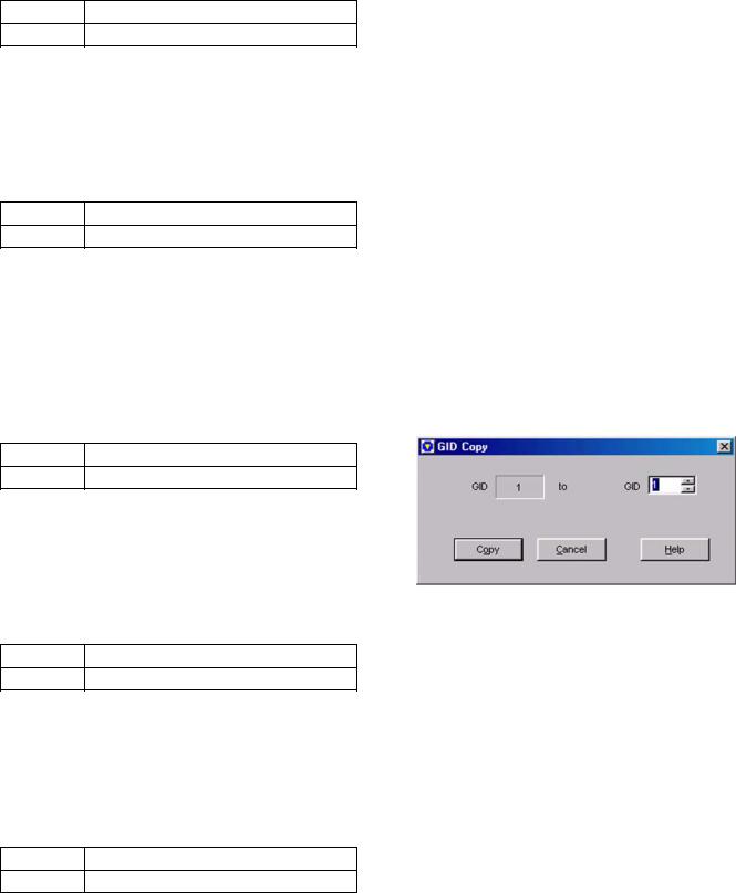
" Power (Transmit Power)
Configure the transmit power of each channel. Select the desired transmit power from the pulldown menu.
Range |
High/ Low |
Default High
Note: Power can be configured only when a value is configured in the Decode ID and Encode ID edit boxes.
" Transpond
Configure to enable or disable the Transpond function by each Group ID. Select the desired Transpond from the pulldown menu.
Range |
Yes/ No |
Default No
Note:
!Transpond can be configured only when a value is configured in the Decode ID and Encode ID edit boxes.
!Transpond cannot be configured when an item other than “None” is selected in the Opt Signal pulldown menu.
"Scan Add
From the pulldown menu, select whether or not the transceiver scans each Group ID during the scan.
Range |
Yes/ No |
Default Yes
Note: Scan Add can be configured only when a value is configured in the Decode ID edit box.
" Optional Signaling
Configure the Optional Signaling of each Group ID. Select the desired Optional Signaling format from the pulldown menu.
Range None/ DTMF/ FleetSync
Default None
Note: Optional Signal can be configured only when a value is configured in the Decode ID edit box.
" TA (Talk Around)
Configure to enable or disable the Talk Around function by each Group ID. Select the desired Talk Around option from the pulldown menu.
Range |
Yes/ No |
Default No
Note: TA can be configured only when a value is configured in the Decode ID edit box.
" Repeater Button
Click “Repeater” to open the Repeater Information window. (Refer to 6.4 Repeater Information Window.)
Note: An error message appears when there is no data configured to a zone.
" Zone Edit Button
Click “Zone Edit” to open the Zone Edit window. (Refer to 6.5 Zone Edit Window.)
Note: An error message appears when there is no data configured to a zone.
" GID Edit Button
Click “GID Edit” to open the GID Edit window. (Refer to 6.6 GID Edit Window.)
" GID Copy ([Shift] + [F3])
Existing GID data can be copied to other channels. To do this, follow the procedures below:
1.Select the GID to be copied.
The GID can be selected by clicking the GID number.
2.Press [Shift] + [F3] on the keyboard. The GID Copy window appears.
Figure 6-9 GID Copy Window
3.Select the desired GID to copy to.
Enter a value directly in the edit box or click the spin button to configure.
4.Click “Copy”.
The configured data is copied to the copy target GID.
Loading...