


 Loading...
CD & HEATER CONTROL RECEIVER
GX-201KHF2/LHF2 /RHF2/SHF2
SERVICE MANUAL (TENTATIVE)
© 2003-8 CREATED IN JAPAN B53-0088-00 (N) 0
SUBARU GENUINE |
Model |
Model Name |
Parts No. |
Destination |
|
|
GX-201LH |
GX-201LHF2 |
86201AG400 |
Europe (left-hand-drive cars) |
|
|
GX-201RH |
GX-201RHF2 |
86201AG300 |
Europe (right-hand-drive cars) |
|
|
GX-201KH |
GX-201KHF2 |
86201AG200 |
Other Areas (right-hand-drive cars) |
|
|
GX-201SH |
GX-201SHF2 |
86201AG500 |
Other Areas (left-hand-drive cars) |
|
Panel assy |
|
|
Panel assy |
||
( |
- |
)* |
GX-201RHF2 |
( - )* |
|
GX-201LHF2 |
|
|
|
||
VOL ADJ |
|
|
|
|
VOL ADJ |
|
CD |
|
CD |
|
|
|
CHR |
FM |
CHR |
FM |
|
|
AM |
|
AM |
|
|
|
LOCAL |
|
|
LOCAL |
|
|
DX |
|
|
DX |
ANTI-THEFT SYSETM |
|
SCAN |
|
|
|
REG |
REG |
|
|
SCAN |
|
|
RDM |
|
|
|
||
|
|
|
RDM |
|
|
TUNE |
|
|
|
|
TUNE |
TRACK |
|
|
|
|
TRACK |
OFF 


 A/C MODE MODE A/C


 OFF
OFF
Panel assy |
Panel assy |
|
( - |
)* |
( - )* |
GX-201SHF2 |
|
GX-201KHF2 |
SCAN |
|
SCAN |
|
CD |
CD |
CHR |
FM |
CHR FM |
|
AM |
AM |
TUNE |
|
TUNE |
TRACK |
|
TRACK |
|
|
|
OFF |
A/C MODE |
MODE A/C |
OFF |
* Part number of panel assy is undecided.
 The knobs with numbers larger than 700 on exploded view are not supplied for service parts because it is difficult to apply grease.
Please change to panel assy (PA1) when you need repair to the knob.
 DC cord for service : E30-3801-15
 Antenna connector replacement cord for service : E30-6255-05
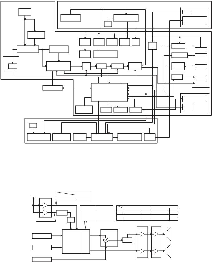
GX-201KHF2/LHF2/RHF2/SHF2
BLOCK DIAGRAM
(X14- ) |
|
|
|
(X89-254) |
|
|
|
|
|
|
|
|
|
|
W1 |
|
|
|
|
|
|
|
|
|
|
J1 |
|
|
FM/AM |
|
IC31 |
|
|
|
IC11 |
|
|
|
IGN |
|
|
|
ANT |
|
|
|
|
|
|
|
|
||||
|
|
|
|
|
|
|
|
|
|
|
|
||
|
|
|
|
CD SERVO |
|
|
BU5V, AUDIO8V, |
|
AIR-CONDITIONER |
||||
|
|
|
|
AVR |
|
|
|
LED10V AVR |
|
||||
|
AM |
FM |
|
|
X25 |
|
UART |
|
|||||
|
|
|
|
|
|
|
|
COMMUNICATION |
|||||
|
|
|
|
|
|
|
|
|
|
|
|
||
|
|
IC11 |
|
|
|
|
|
|
|
|
|
|
|
|
|
FM |
|
|
|
|
|
|
|
|
|
|
|
|
|
DIVERSITY |
|
|
Q602 |
Q605 |
Q104 |
Q102 |
|
Q813 |
|
|
|
|
A3 |
|
|
IC12 |
DC/DC |
DC/DC |
AM 8V FM 8V |
SW |
Q808 |
Q815 |
J2 |
||
|
|
|
AVR |
AVR |
AVR |
AVR |
|
5V |
IGN |
BU DET |
|||
(2-73, |
FA/AM TUNER |
|
AM NOISE |
A1 |
A2 |
|
|
|
|
DET |
|
||
|
|
|
|
|
|
BU |
|||||||
|
|
|
|
|
|
Q807 |
|||||||
2-74) |
(FRONT END) |
|
CANCELLER |
DC/DC |
DC/DC |
|
|
|
|
|
|
||
ONLY |
|
|
|
|
|
|
|
|
|
ACC DET |
|
||
|
|
|
|
AUDIO |
HEAT CONTROL |
|
|
|
ACC |
||||
|
|
|
|
|
|
|
|
||||||
IC13, |
|
|
IC22 |
IC23 |
|
|
|
IC41 |
|
Q802,850,851 |
|
||
14 |
|
|
|
E-VOL/ |
Q401,402 IC31-34 |
|
|
||||||
|
|
|
FRONT NAVI |
|
POWER |
|
ILLM +/- |
|
|||||
RDS |
|
|
|
MUTE |
FIX-EQ |
|
|
|
|||||
|
|
|
SIGNAL |
|
|
ILLM +/- |
|||||||
|
|
|
SW |
|
AMP |
|
DET |
||||||
|
|
|
|
PROCESSOR IC |
|
|
|
|
|
|
|||
|
|
|
|
REAR |
|
|
|
|
|
|
|
|
|
|
|
|
|
|
|
|
|
|
|
|
Q816 |
|
|
|
|
|
|
|
|
|
|
|
|
|
|
|
|
|
|
|
|
|
|
|
|
|
|
|
|
P-ANT |
P-ANT |
|
|
|
|
|
|
IC81 |
|
|
|
|
|
|
SP |
|
|
|
|
|
|
|
|
|
|
|
|
|
|
|
|
|
CD MECHA |
|
|
|
|
|
|
|
|
|
|
|
|
|
|
|
|
SYSTEM u-COM |
|
|
|
J1 |
|
||
|
|
|
|
|
|
|
|
|
|
|
|
BUS |
|
|
|
|
|
|
|
|
|
|
|
|
|
(COMMUNICATION) |
|
|
|
|
|
|
X81 |
IC82 |
|
BZ81 |
|
IC83 |
|
BUS |
|
|
|
|
|
|
OSC |
|
|
|
|
||||
|
|
|
|
|
RESET |
BUZZER |
|
BUS I/F |
|
(AUDIO) |
|||
|
|
|
|
|
12.582MHz |
|
|
|
|
||||
|
|
|
|
|
|
|
|
|
|
|
|
|
|
|
|
(X25-929) |
|
|
|
|
|
|
|
|
|
|
|
|
|
X89 |
|
|
|
|
|
|
|
|
|
|
|
|
|
|
|
|
|
|
|
|
|
|
Q24, |
|
|
|
|
|
|
ED1 |
|
IC1 |
|
ED2 |
|
|
25 |
|
|
|
|
LED |
|
AUDIO |
KEY |
PANEL |
|
HEAT CONTROL |
UART |
|
|
||
|
|
ILLUMINATION |
FL DISPLAY |
MATRIX |
u-COM |
|
FL DISPLAY |
I/F |
|
|
|||
LEVEL DIAGRAM
ANT |
|
FM |
|
|
|
|
|
|
|
GX-201KHF2/SHF2 500mV-rms |
|
|
|
|
|
|
|||
|
|
|
|
|
|
|
|||
TUNER |
GX-201RHF2/LHF2 270mV-rms |
LEVEL DIFFERENCE OF EACH SAUCE |
|
||||||
|
|
|
(CD 1W OUTPUT) |
|
|
|
|||
FM |
IC12 |
GX-201KHF2 |
GX-201RHF2 |
|
GX-201KHF2/SHF2 |
GX-201RHF2/LHF2 |
|||
GX-201SHF2 |
GX-201LHF2 |
AM |
1kHz 30% mod. |
-16dB 1kHz 30% mod. |
-14dB |
||||
|
|
||||||||
AM |
AM/NC |
CD : +5dB |
CD : +5dB |
FM |
1kHz 75kHz dev. |
-6dB 1kHz 40kHz dev. |
-8dB |
||
0dB |
CH : +5dB |
CH : +5dB |
CD |
1kHz 0dB |
0dB |
1kHz 0dB |
0dB |
||
|
FM : +7dB |
FM : +10.5dB |
|||||||
|
CH |
1kHz 0dB |
0dB 1kHz 0dB |
0dB |
|||||
AM : 215mV-rms |
LPF |
AM : +16dB |
AM : +18dB |
||||||
|
-7.5dB |
|
|
|
IC31-34 |
IC41 |
|
||
|
IC22 |
|
IC23 |
|
|
||||
|
|
|
FIX-EQ |
AMP |
|
||||
|
|
FRONT SELECTOR |
|
|
|||||
|
MPX, |
Q401, |
|
|
FRONT |
||||
CD-MECHA |
|
-1.5dB |
402 |
|
|
SP |
|||
LOUD, |
|
|
+26dB |
||||||
|
FAD, |
|
|
+7.5dB |
|
||||
CD : 1.2V-rms |
E-VOL, |
|
|
MUTE |
|
|
|
||
|
BASS, |
BAL |
-23.8dB |
|
-0.5dB |
|
|
|
|
|
TRE, |
|
|
|
|
|
|||
EXT-UNIT |
|
|
|
|
|
|
|
||
MID |
REAR |
|
|
|
|
REAR |
|||
|
|
|
|
|
|||||
CH : 1.2V-rms |
|
|
|
|
|
||||
|
|
|
|
-3dB |
+26dB |
SP |
|||
|
|
|
|
|
|
||||
NAVI
NAVI : 1.2V-rms
2
GX-201KHF2/LHF2/RHF2/SHF2
COMPONENTS DESCRIPTION
● SYNTHESIZER UNIT (X14-694x-xx)
Ref. No. |
Application / Function |
Operation / Condition / Compatibility |
|
|
|
IC11 |
FM diversity IC |
FM diversity switching (Only for GX-201JHF2/KHF2) |
|
|
|
IC12 |
AM noise canceller IC |
AM noise canceller |
|
|
|
IC13 |
2-piece ope-amp |
RDS noise amp (Only for GX-201LHF2/RHF2) |
|
|
|
IC14 |
RDS demodulation IC |
RDS demodulation (Only for GX-201LHF2/RHF2) |
|
|
|
IC22 |
Electronic volume |
BASS/MID/TRE, MPX, Mute, Electronic volume |
|
|
|
IC23 |
Ope-amp with switch |
Audio/NAVI switching |
|
|
|
IC31~34 |
4-piece ope-amp |
FIX-EQ |
|
|
|
IC35 |
2-piece ope-amp |
1/2 VCC output |
|
|
|
IC41 |
Power amp |
4ch power amp |
|
|
|
IC81 |
System -com |
System control |
|
|
|
IC82 |
Reset IC |
System reset detection |
|
|
|
IC83 |
I2C BUS IC |
F-BUS communication |
|
|
|
IC84 |
2-piece NOR circuit |
For hard muting |
|
|
|
IC85 |
EEPROM |
Bug counter-measure |
|
|
|
IC86,87 |
Inverter circuit |
F-BUS control |
|
|
|
Q101 |
Diversity switch |
When turned ON, turns diversity OFF (Only for GX-201JHF2/KHF2) |
|
|
|
Q102,103 |
FM power supply switch |
When FM, 8V output |
|
|
|
Q104,105 |
AM power supply switch |
When AM, 8V output |
|
|
|
Q106 |
IF count detection |
When detecting IF count, Lo output |
|
|
|
Q107 |
RDS data buffer |
RDS data buffer output (Only for GX-201LHF2/RHF2) |
|
|
|
Q108 |
S-meter buffer |
S-meter voltage output |
|
|
|
Q151,152 |
Noise amp |
Noise detection constant switching (Only for GX-201LHF2/RHF2) |
|
|
|
Q153 |
Noise amp |
Noise detection output buffer (Only for GX-201LHF2/RHF2) |
|
|
|
Q202 |
Mute switch |
For muting with in electronic volume |
|
|
|
Q401,402 |
NAVI mute |
For NAVI muting at interruption |
|
|
|
Q403 |
SVR switch |
For SVR discharging |
|
|
|
Q404 |
SVR switch |
For SVR discharging at over voltage |
|
|
|
Q601,602 |
Audio DC/DC power supply switch |
For DC/DC audio |
|
|
|
Q604,605 |
Heater DC/DC power supply switch |
For DC/DC heater |
|
|
|
Q606,607 |
DC/DC control switch |
For switching internal frequency |
|
|
|
Q650 |
Audio DC/DC power supply switch |
For DC/DC audio |
|
|
|
Q651 |
Heater DC/DC power supply switch |
For DC/DC heater |
|
|
|
Q801 |
Buzzer switch |
For buzzer |
|
|
|
Q802 |
Illumination + detection |
For illumination + detection |
|
|
|
Q803 |
Reset output switch for F-BUS |
When resetting F-BUS, Hi output |
|
|
|
Q804 |
NAVI mute switch |
When muting NAVI, Hi output |
|
|
|
Q805 |
IF count detection |
When detecting IF count, Lo output |
|
|
|
Q806 |
P-ANT circuit control switch |
When tuner, GND electric potential output |
|
|
|
Q807 |
ACC detection |
When ACC ON detection, Lo output |
|
|
|
Q808 |
IGN detection |
When IGN ON detection, Lo output |
|
|
|
Q809 |
SYS_ON current buffer |
When SYS_ON Hi, Lo output |
|
|
|
Q810 |
Hard reset switch |
When HARD_RESET ON, Lo output |
|
|
|
Q812 |
BUS_OFF switch |
When F-BUS system OFF, Hi output |
|
|
|
3
GX-201KHF2/LHF2/RHF2/SHF2
COMPONENTS DESCRIPTION
Ref. No. |
Application / Function |
Operation / Condition / Compatibility |
|
|
|
Q813 |
P-ON5V power supply switch |
For P-ON5V |
|
|
|
Q815 |
BU detection |
When BU ON, Lo output |
|
|
|
Q816 |
P-ANT circuit control switch |
When tuner, BU electric potential output |
|
|
|
Q817,818 |
P-ANT circuit protection |
P-ANT short circuit protection |
|
|
|
Q820 |
F-BUS mute output |
When mute ON, Hi output |
|
|
|
Q821 |
BUS_ON detection |
When F-BUS system ON, Hi input |
|
|
|
Q822 |
BUS_ON switch |
When F-BUS system ON, Hi output |
|
|
|
Q850,852 |
Illumination - detection switch |
When detecting illumination -, Hi output |
|
|
|
Q853 |
Illumination - detection switch |
When detecting illumination -, Lo output |
|
|
|
● SWITCH UNIT (X25-929x-xx)
Ref. No. |
Application / Function |
Operation / Condition / Compatibility |
|
|
|
IC1 |
Display control -com |
VFD control, Key intake |
|
|
|
IC3 |
EEPROM |
For bug counter-measures |
|
|
|
Q1 |
Audio VFD5V switch |
When audio VFD ON, 5V output |
|
|
|
Q2 |
Audio VFD5V switch |
When audio DC/DC ON, Lo output |
|
|
|
Q4 |
Heater VFD5V switch |
When heater VFD ON, 5V output |
|
|
|
Q5 |
Heater VFD5V switch |
When heater DC/DC ON, Lo output |
|
|
|
Q11 |
F differential indicator power supply switch |
When F-differential indicator ON, 5V output |
|
|
|
Q12 |
R differential indicator power supply switch |
When R-differential indicator ON, 5V output |
|
|
|
Q21 |
Multiple-push reset circuit detection |
When detecting REP/RDM, DWN_SEEK, Hi output |
|
|
|
Q22 |
Multiple-push reset circuit detection |
When resetting by multiple push, Lo output |
|
|
|
Q23 |
Multiple-push reset circuit detection |
When TONE (BAL/FAD) detected, Lo output |
|
|
|
Q24 |
Heater UART communication control |
Heater UART communication control (TX) |
|
|
|
Q25 |
Heater UART communication control |
Heater UART communication control (RX) |
|
|
|
Q26 |
SW5V power supply switch |
When IGN ON, 5V output |
|
|
|
Q27 |
Panel illumination switch |
When panel illumination ON, 10V output |
|
|
|
Q28 |
Panel illumination switch |
When panel illumination ON, GND electrical potential |
|
|
|
Q29 |
F differential indicator dimmer control |
When dimmer OFF, GND electrical potential |
|
|
|
Q30 |
R differential indicator dimmer control |
When dimmer OFF, GND electrical potential |
|
|
|
Q33 |
System reset detection |
When system is reset, Hi output |
|
|
|
Q34 |
Dimmer current counter-measure |
When audio encoder ON, 5V output |
|
|
|
Q35 |
System reset detection |
When system is reset, Lo output |
|
|
|
Q36,37 |
6CD breakup counter-measure |
FL (H) discharge circuit |
|
|
|
● DAUGHTER UNIT (X89-2540-01)
Ref. No. |
Application / Function |
Operation / Condition / Compatibility |
|
|
|
IC11 |
Various constant voltage power supply output |
5V, 8V, 10V constant voltage power supply |
|
|
|
IC31 |
CD servo 8V power supply |
For CD servo |
|
|
|
Q101 |
Panel illumination power supply switch |
When illumination + input, 5V output |
|
|
|
Q301~303 |
CD servo power supply switch |
For CD servo |
|
|
|
4
Loading...