


 Loading...
HOME CINEMA CONTROL CENTER
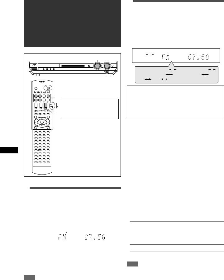
RX-E5S/RX-E51B
INSTRUCTIONS
LVT1141-003C
[B]

Warnings, Cautions and Others
IMPORTANT for the U.K.
DO NOT cut off the mains plug from this equipment. If the plug fitted is not suitable for the power points in your home or the cable is too short to reach a power point, then obtain an appropriate safety approved extension lead or consult your dealer.
BE SURE to replace the fuse only with an identical approved type, as originally fitted.
If nonetheless the mains plug is cut off ensure to remove the fuse and dispose of the plug immediately, to avoid a possible shock hazard by inadvertent connection to the mains supply.
If this product is not supplied fitted with a mains plug then follow the instructions given below:
IMPORTANT:
DO NOT make any connection to the terminal which is marked with the letter E or by the safety earth symbol or coloured green or green-and-yellow.
The wires in the mains lead on this product are coloured in accordance with the following code:
Blue : Neutral
Brown : Live
As these colours may not correspond with the coloured markings identifying the terminals in your plug proceed as follows:
The wire which is coloured blue must be connected to the terminal which is marked with the letter N or coloured black.
The wire which is coloured brown must be connected to the terminal which is marked with the letter L or coloured red.
IF IN DOUBT - CONSULT A COMPETENT ELECTRICIAN.
Caution–– STANDBY/ON button!
Disconnect the mains plug to shut the power off completely. The  STANDBY/ON button in any position does not disconnect the mains line. The power can be remote controlled.
CAUTION
To reduce the risk of electrical shocks, fire, etc.:
1.Do not remove screws, covers or cabinet.
2.Do not expose this appliance to rain or moisture.
CAUTION
•Do not block the ventilation openings or holes.
(If the ventilation openings or holes are blocked by a newspaper or cloth, etc., the heat may not be able to get out.)
•Do not place any naked flame sources, such as lighted candles, on the apparatus.
•When discarding batteries, environmental problems must be considered and local rules or laws governing the disposal of these batteries must be followed strictly.
•Do not expose this apparatus to rain, moisture, dripping or splashing and that no objects filled with liquids such as vases, shall be placed on the apparatus.
G-1
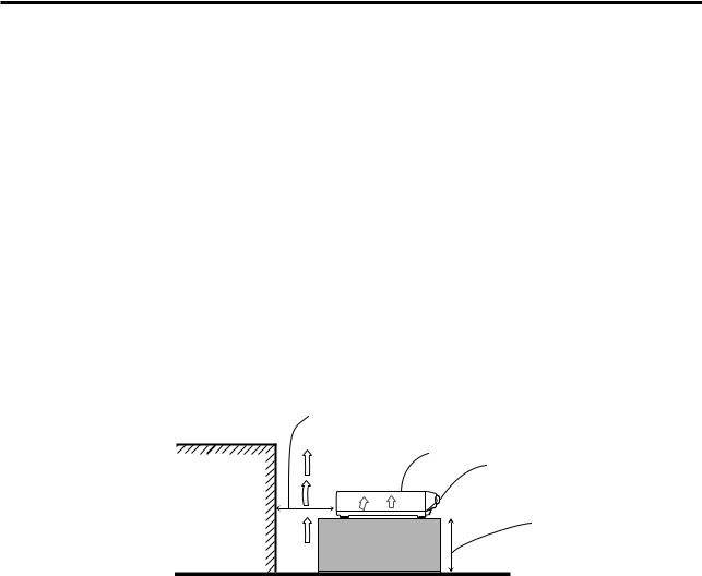
Caution: Proper Ventilation
To avoid risk of electric shock and fire and to protect from damage. Locate the apparatus as follows:
Front: |
No obstructions open spacing. |
Sides: |
No obstructions in 10 cm from the sides. |
Back: |
No obstructions in 15 cm from the back. |
Bottom: |
No obstructions, place on the level surface. |
In addition, maintain the best possible air circulation as illustrated.
|
Spacing 15 cm or more |
|
RX-E5S/RX-E51B |
|
Front |
Wall or |
|
obstructions |
Stand height |
|
|
|
15 cm or more |
|
Floor |
G-2

SAFETY INSTRUCTIONS
“SOME DOS AND DON’TS ON THE SAFE USE OF EQUIPMENT”
This equipment has been designed and manufactured to meet international safety standards but, like any electrical equipment, care must be taken if you are to obtain the best results and safety is to be assured.
Do read the operating instructions before you attempt to use the equipment.
Do ensure that all electrical connections (including the mains plug, extension leads and interconnections between pieces of equipment) are properly made and in accordance with the manufacturer’s instructions. Switch off and withdraw the mains plug when making or changing connections.
Do consult your dealer if you are ever in doubt about the installation, operation or safety of your equipment.
Do be careful with glass panels or doors on equipment.
DON’T continue to operate the equipment if you are in any doubt about it working normally, or if it is damaged in any way—switch off, withdraw the mains plug and consult your dealer.
DON’T remove any fixed cover as this may expose dangerous voltages.
DON’T leave equipment switched on when it is unattended unless it is specifically stated that it is designed for unattended operation or has a standby mode.
Switch off using the switch on the equipment and make sure that your family know how to do this. Special arrangements may need to be made for infirm or handicapped people.
DON’T use equipment such as personal stereos or radios so that you are distracted from the requirements of traffic safety. It is illegal to watch television whilst driving.
DON’T listen to headphones at high volume as such use can permanently damage your hearing.
DON’T obstruct the ventilation of the equipment, for example with curtains or soft furnishings.
Overheating will cause damage and shorten the life of the equipment.
DON’T use makeshift stands and NEVER fix legs with wood screws—to ensure complete safety always fit the manufacturer’s approved stand or legs with the fixings provided according to the instructions.
DON’T allow electrical equipment to be exposed to rain or moisture.
ABOVE ALL
—NEVER let anyone, especially children, push anything into holes, slots or any other opening in the case—this could result in a fatal electrical shock.;
—NEVER guess or take chances with electrical equipment of any kind—it is better to be safe than sorry!
G-3

Table of Contents
Parts identification ................................................ |
2 |
Getting started ...................................................... |
4 |
Before Installation .................................................................. |
4 |
Checking the supplied accessories ....................................... |
4 |
Putting batteries in the remote control ................................... |
4 |
Connecting the FM and AM (MW) antennas ......................... |
5 |
Connecting the speakers ....................................................... |
6 |
Connecting video components .............................................. |
7 |
Connecting the power cord .................................................... |
9 |
Basic operations ................................................. |
10 |
1 Turn on the power ............................................................ |
10 |
2 Select the source to play .................................................. |
10 |
3 Adjust the volume ............................................................ |
11 |
Selecting the digital decode mode ....................................... |
11 |
Adjusting the subwoofer audio position ............................... |
12 |
Activating TV Direct ............................................................. |
12 |
Turning off the sounds temporarily ...................................... |
13 |
Changing the display brightness .......................................... |
13 |
Turning off the power with the Sleep Timer ......................... |
13 |
Basic settings ...................................................... |
14 |
Setting the speaker information automatically |
|
—Smart Surround Setup ............................................... |
14 |
Basic setting items ............................................................... |
15 |
Operating procedure ............................................................ |
16 |
Setting the speakers ............................................................ |
16 |
Setting bass sound .............................................................. |
17 |
Setting the virtual surround back speaker—VIRTUAL SB ... |
18 |
Selecting the main or sub channel—DUAL MONO ............. |
18 |
Using the Midnight mode—MIDNIGHT M............................ |
18 |
Setting the digital input (DIGITAL IN) terminals |
|
—DIGITAL IN1/2 ............................................................ |
19 |
Setting Auto Surround—AUTO SURRND ............................ |
19 |
Setting the Auto Function mode—AUTO MODE ................. |
19 |
Sound adjustments ............................................. |
20 |
Basic adjustment items ........................................................ |
20 |
Operating procedure ............................................................ |
20 |
Adjusting speaker output level ............................................. |
21 |
Adjusting the sound parameters for the |
|
Surround/DSP modes ................................................... |
21 |
Adjusting the bass sounds ................................................... |
22 |
Adjusting the equalization patterns |
|
—D EQ 63Hz/250Hz/1kHz/4kHz/16kHz ........................ |
22 |
Tuner operations ................................................. |
23 |
Tuning in to stations manually .............................................. |
23 |
Using preset tuning .............................................................. |
23 |
Selecting the FM reception mode ........................................ |
24 |
Using the Radio Data System (RDS) to |
|
receive FM stations ....................................................... |
25 |
Searching for a program by PTY codes ............................... |
26 |
Switching to broadcast program of your choice |
|
temporarily ..................................................................... |
28 |
Creating realistic sound fields ........................... |
29 |
Reproducing theatre ambience ........................................... |
29 |
Introducing the Surround modes ......................................... |
29 |
Introducing the DSP modes ................................................. |
31 |
Using the Surround/DSP modes ......................................... |
32 |
Operating other JVC products ........................... |
34 |
Operating other manufacturers’ products ........ |
36 |
Troubleshooting .................................................. |
39 |
Specifications ...................................................... |
40 |
1
Parts identification
|
1 |
|
|
2 |
|
|
3 |
e |
|
|
|
|
|
r |
|
4 |
t |
|
|
y |
identificationParts |
5 |
|
6 |
|
|
|
7 |
|
|
8 |
|
|
9 |
|
|
|
u |
|
|
i |
|
p |
o |
|
; |
|
|
q |
|
|
a |
|
|
|
|
|
w |
s |
|
|
d |
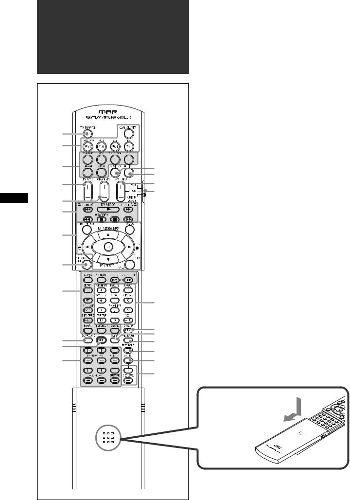
Remote control
See pages in parentheses for details.
1 TV DIRECT button (12)
2 Standby/on buttons (10, 34 – 38)
 AUDIO, DVR/DVD
  , VCR
, VCR  , STB
, STB  , TV
, TV 
3• Source selecting buttons (10, 12, 23, 34, 36, 37) DVR/DVD, VCR, TV, FM/AM, VIDEO
• STB CONTROL button (38)
4 TV VOL (volume) +/– button (34, 36)
5 CHANNEL +/– button (34 – 38)
6• Operating buttons for video components (34, 35, 37)
4, 3, ¢, 1, 7, 8, ¡
•Operating buttons for tuner (23, 24)
(TUNING, FM MODE, TUNING 9, MEMORY
7• Operating buttons for DVD recorder or DVD player* (35) TOP MENU, MENU, cursor buttons (3, 2, 5, ∞), ENTER, ON SCREEN
•Operating buttons for RDS (25, 26, 28)
PTY 9, PTY (, TA/NEWS/INFO, PTY SEARCH,
DISPLAY
8 SMART SURROUND SETUP button (14)
9 Operating buttons for DVD recorder or DVD player* (35) AUDIO, SUBTITLE, DVD, ZOOM, HDD, SOUND EFFECT, SET UP,  , VFP, PROGRESSIVE, ANGLE,
SLIDE EFFECT, RETURN, TITLE/GROUP, CANCEL p SURROUND button (32)
q SOUND button (10 – 12, 18, 21, 22)
w Adjusting buttons for speaker and subwoofer output levels (21)
FRONT L +/–, FRONT R +/–, CENTER +/–, SURR L +/–, SURR R +/–, SUBWFR +/–
e TV/VIDEO button (34, 36) r MUTING button (13)
t VOLUME +/– button (11)
yMode selector (10, 34 – 37) DVR, DVD, AUDIO/TV/VCR/STB
u• Numeric buttons (24, 34 – 38)
•Adjusting buttons (10 – 12, 18, 21, 22)
A/D INPUT, DECODE, EFFECT, BASS BOOST, C.TONE,
MIDNIGHT, A.POSITION
•TV RETURN button (34)
i• DISPLAY button* (35)
•DIMMER button (13, 35) o SLEEP button (13)
; REC PAUSE button (35) a TEST TONE button (21) s D.EQ FREQ button (22)
d D.EQ LEVEL +/– buttons (22)
*These buttons can be used for operating a JVC DVD recorder or DVD player with the mode selector set to “DVR” or “DVD”
(see page 35).
If these buttons do not function normally, use the remote control supplied with your DVD recorder or DVD player. Refer also to the manuals supplied with the DVD recorder or DVD player for details.
To open the cover of the remote control, push here then slide downward.
2
See pages in parentheses for details.
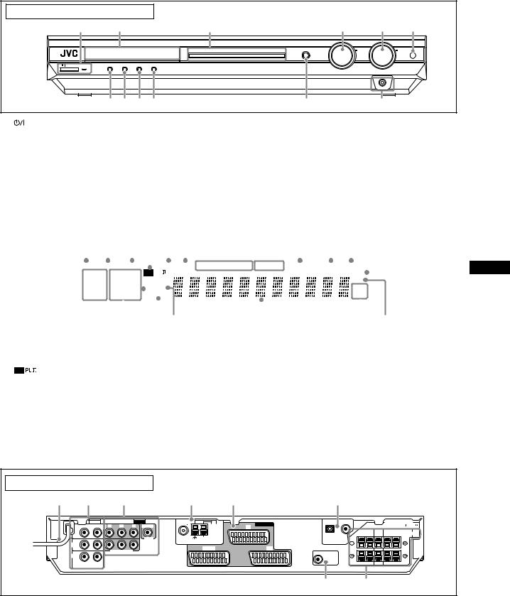
Front panel |
|
|
|
|
|
|
|
|
|
|
|
|
|
1 |
|
2 |
|
3 |
|
|
|
|
|
4 |
5 |
6 |
|
|
|
|
|
DVR/DVD |
VCR |
VIDEO |
TV |
FM |
AM |
SET / TUNER PRESET |
SOURCE |
|
MASTER |
|
|
|
|
|
|
|
|
|
|
|
SELECTOR |
|
VOLUME |
|
|
|
|
|
|
|
|
|
|
|
/ MULTI JOG |
|
|
STANDBY / ON |
TV DIRECT |
SETTING |
ADJUST |
SURROUND |
|
|
|
|
|
|
|
|
|
|
|
|
|
|
|
HOME CINEMA CONTROL CENTER |
|
|
|
|
|
||
|
|
|
|
|
|
|
|
|
|
|
|
PHONES |
|
|
7 8 9 p |
|
|
|
|
|
q |
|
w |
|
|||
1 |
STANDBY/ON button and standby lamp (10) |
7 |
TV DIRECT button (12) |
2 |
Display window (see below) |
8 |
SETTING button (16) |
3 |
Source lamps |
9 |
ADJUST button (20) |
|
DVR/DVD, VCR, VIDEO, TV, FM, AM |
p SURROUND button (33) |
|
4 |
• SOURCE SELECTOR (10, 24) |
q • SET button (16, 20) |
|
|
• MULTI JOG (16, 20, 24, 33) |
|
• TUNER PRESET button (24) |
5 |
MASTER VOLUME control (11) |
w PHONES jack (11) |
|
6 |
Remote sensor (4) |
|
|
|
|
|
|
|
|
|
|
|
|
|
|
|
|
|
|
|
|
|
|
|
|
|
|
|
|
|
|
|
|
|
|
|
|
|
|
|
|
Display window |
|
|
|
|
|
|
|
|
|
|
|
|
|
|
|
|
|
|
|
|
|
|
|
|
|
|
|||||||
|
|
|
|
|
|
|
|
|
|
|
|
|
|
|
|
|
|
|
|
|
|
|
|
8 9 0 - = |
|
|
|||||||||
|
|
1 2 3 4 5 6 |
7 |
|
|
||||||||||||||||||||||||||||||
|
|
|
|
|
|
|
|
|
|
|
|
|
|
|
|
|
|
|
|
|
|
|
|
|
|
|
|
|
|
|
|
|
|
|
|
|
|
|
|
|
|
|
|
|
|
|
|
|
|
|
|
|
|
|
|
|
|
|
|
|
|
|
|
|
|
|
|||||
|
|
|
|
|
|
C.TONE |
VIRTUAL SB |
|
AUDIO . BASS |
TA NEWS INFO RDS |
TUNED ST AUTO MUTING SLEEP AUTO MODE |
|
|
|
|
||||||||||||||||||||
|
|
|
|
|
|
|
|
|
|
|
|||||||||||||||||||||||||
|
|
|
LPCM |
|
L |
|
|
C |
|
R |
|
|
|
|
PL |
|
|
|
|
|
|
|
ATT |
|
|
|
|
||||||||
|
|
|
|
|
|
|
|
|
|
|
|
|
|
|
|
|
|
|
|||||||||||||||||
|
|
|
DOLBY D |
S . WFR LFE |
NEO : 6 |
|
|
|
|
|
|
|
HP |
|
|
||||||||||||||||||||
|
|
|
DTS |
AAC |
|
|
|
|
|
|
|
|
|
DSP |
|
|
|
|
|
|
|
MHz |
|
|
|||||||||||
|
|
|
LS |
SB |
RS |
|
|
|
|
|
|
|
|
|
|||||||||||||||||||||
|
|
|
96 / |
24 |
|
AUTO SR |
|
|
|
|
|
|
|
kHz |
|
|
|||||||||||||||||||
|
|
|
|
|
|
|
|
|
|
|
|
|
|
|
|
|
|
|
|
|
|
|
|
|
|
|
|
|
|
|
|
|
|
|
|
|
|
|
|
|
|
|
|
|
|
|
|
|
|
|
|
|
|
|
|
|
|
|
|
|
|
|
|
|
|
|
|||||
|
|
~ |
|
|
|
! |
|
@ # $ |
|
|
|
% |
|
|
|
^ |
|
|
& |
|
|||||||||||||||
|
|
|
|
|
|
|
|
|
|
|
|
|
|
|
|
|
|
|
|
|
|
|
|
|
|
|
|
|
|
|
|
|
|
||
|
|
|
|
|
|
|
|
|
|
|
|
|
|
|
|
|
|
|
|
|
|
|
|
|
|
|
|
|
|
|
|
|
|
|
|
1 |
EQ indicator (22) |
|
|
|
|
|
|
|
|
|
|
|
|
|
|
|
|
- AUTO MODE indicator (19) |
|
|
|
|
|
|
|||||||||||
2 |
C.TONE indicator (21) |
|
|
|
|
|
|
|
|
|
|
|
|
|
|
|
|
= ATT (attenuator) indicator (22) |
|
|
|
|
|
|
|||||||||||
3 |
VIRTUAL SB indicator (18, 29, 30) |
|
|
|
|
|
|
|
|
|
|
~ Digital signal format indicators (11) |
|
|
|||||||||||||||||||||
4 |
indicator (29) |
|
|
|
|
|
|
|
|
|
|
|
|
|
|
|
|
LPCM (Linear PCM), DOLBY D (Dolby Digital), DTS, 96/24 |
|||||||||||||||||
5 |
AUDIO P. (position) indicator (12) |
|
|
|
|
|
|
|
|
|
|
! Signal and speaker indicators (13) |
|
|
|||||||||||||||||||||
6 |
BASS indicator (22) |
|
|
|
|
|
|
|
|
|
|
|
|
|
|
|
|
@ DSP indicator (30, 31) |
|
|
|
|
|
|
|||||||||||
7 |
RDS operation indicators (25, 28) |
|
|
|
|
|
|
|
|
|
|
# AUTO SR (surround) indicator (19) |
|
|
|||||||||||||||||||||
|
|
TA, NEWS, INFO, RDS |
|
|
|
|
|
|
|
|
|
|
|
|
|
|
|
|
$ 3D indicator (30, 31) |
|
|
|
|
|
|
||||||||||
8 |
Tuner operation indicators (23) |
|
|
|
|
|
|
|
|
|
|
|
|
|
|
% Main display |
|
|
|
|
|
|
|||||||||||||
|
|
TUNED, ST (stereo) |
|
|
|
|
|
|
|
|
|
|
|
|
|
|
|
|
^ Frequency unit indicators |
|
|
|
|
|
|
||||||||||
9 |
AUTO MUTING indicator (24) |
|
|
|
|
|
|
|
|
|
|
|
|
|
|
MHz (for FM station), kHz (for AM station) |
|||||||||||||||||||
0 |
SLEEP indicator (13) |
|
|
|
|
|
|
|
|
|
|
|
|
|
|
|
|
& HP (headphones) indicator (11, 30, 31) |
|
|
|||||||||||||||
Rear panel |
|
|
|
|
|
|
|
|
|
|
|
|
|
||
1 |
2 |
|
3 |
|
|
4 |
5 |
6 |
|
|
|
|
|
||
|
|
AUDIO |
|
|
|
VIDEO |
|
|
2(VIDEO) |
1(DVR/DVD) |
|
|
CAUTION: SPEAKER |
||
|
|
MONITOR |
Y |
PB |
PR |
VIDEO IN |
FM 75 |
AM LOOP |
AV IN/OUT |
|
|
|
IMPEDANCE 6 |
~ 16 |
|
|
|
OUT |
|
|
|
|
|
|
TV |
|
|
|
|
|
|
|
|
|
|
|
|
|
|
|
|
FRONT |
CENTER |
SURROUND |
SPEAKERS |
||
|
|
|
|
|
|
|
|
|
|
RIGHT |
LEFT |
|
RIGHT |
LEFT |
|
|
|
|
|
|
|
|
COAXIAL |
|
|
|
|
||||
|
|
|
|
|
|
VIDEO |
AM EXT |
|
|
|
|
|
|
|
|
|
|
|
|
|
|
|
|
|
|
|
|
|
|
||
|
DVR/DVD |
|
|
|
|
|
|
ANTENNA |
DIGITAL IN |
|
|
|
|
|
|
|
IN |
|
|
|
|
|
|
DVR/DVD |
VCR |
|
|
|
|
|
|
|
|
|
|
COMPONENT |
|
|
|
|
|
|
|
|
|
||
|
VIDEO |
|
|
|
|
|
|
SUBWOOFER |
|
|
|
|
|
|
|
|
|
|
|
|
|
|
|
|
|
|
|
|
|
||
|
IN |
|
|
|
|
|
|
|
OUT |
|
|
|
|
|
|
|
RIGHT |
LEFT |
|
|
|
|
|
|
|
|
|
|
|
|
|
|
|
|
|
|
|
|
|
|
7 |
8 |
|
|
|
|
|
1 |
Power cord (9) |
6 |
DIGITAL IN terminals (9) |
2 |
AUDIO jacks (8, 9) |
|
Coaxial: 1(DVR/DVD) |
|
MONITOR OUT, DVR/DVD IN, VIDEO IN |
|
Optical: 2(VIDEO) |
3 |
VIDEO jacks (8, 9) |
7 |
SUBWOOFER OUT jack (6) |
|
COMPONENT (Y, PB, PR): MONITOR OUT, DVR/DVD IN |
8 |
SPEAKERS terminals (6) |
|
VIDEO (composite video): VIDEO IN |
|
FRONT, CENTER, SURROUND |
4 |
ANTENNA terminals (5) |
|
|
5AV IN/OUT terminals (7) TV, DVR/DVD, VCR
Parts identification
3
Getting started
Getting started
Before Installation
General precautions
•Be sure your hands are dry.
•Turn the power off to all components.
•Read the manuals supplied with the components you are going to connect.
Locations
•Install the receiver in a location that is level and protected from moisture and dust.
•The temperature around the receiver must be between –5˚C and 35˚C.
•Make sure there is good ventilation around the receiver. Poor ventilation could cause overheating and damage the receiver.
Handling the receiver
•Do not insert any metal object into the receiver.
•Do not disassemble the receiver or remove screws, covers, or cabinet.
•Do not expose the receiver to rain or moisture.
The receiver has a built-in cooling fan which operates while the receiver is turned on. Be sure to leave enough ventilation to obtain sufficient cooling effect.
CAUTION:
Do not connect the AC power plug to the wall outlet until all connections are completed.
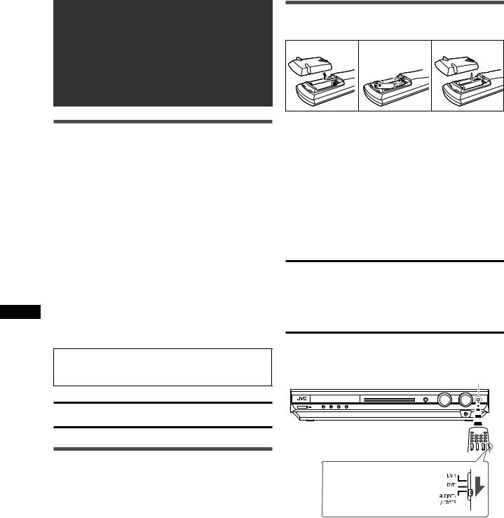
Putting batteries in the remote control
Before using the remote control, put two supplied batteries first.
1 |
2 |
3 |
1Press and slide the battery cover on the back of the remote control.
2Insert batteries.
Make sure to match the polarity: (+) to (+) and (–) to (–).
3 Replace the cover.
If the range or effectiveness of the remote control decreases, replace the batteries. Use two R6(SUM-3)/AA(15F) type dry-cell batteries.
•Supplied butteries are for initial setup. Replace for continued use.
CAUTION:
Follow these precautions to avoid leaking or cracking cells:
•Place batteries in the remote control so they match the polarity:
(+) to (+) and (–) to (–).
•Use the correct type of batteries. Batteries that look similar may differ in voltage.
•Always replace both batteries at the same time.
•Do not expose batteries to heat or flame.
When using the remote control, aim the remote control directly at the remote sensor on the front panel.
Remote sensor
Checking the supplied accessories
Check to be sure you have all of the following supplied accessories. If anything is missing, contact your dealer immediately.
•Remote control (× 1)
•Batteries (× 2)
•AM (MW) loop antenna (× 1)
•FM antenna (× 1)
•SCART cable (× 1)
•Digital coaxial cable (× 1)
To operate the receiver, set the mode selector to “AUDIO/TV/VCR/STB.”
4
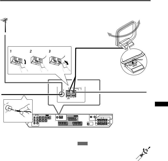
Connecting the FM and AM (MW) antennas
AM (MW) loop antenna (supplied)
If FM reception is poor, connect an outdoor FM antenna (not supplied).
Snap the tabs on the loop into the slots of the base to assemble the AM (MW) loop antenna.
FM antenna (supplied)
FM 75 |
AM LOOP |
|
COAXIAL |
AM EXT |
ANTENNA
If AM (MW) reception is poor, connect an outdoor single vinylcovered wire (not supplied).
Getting started
AM (MW) antenna connection
Connect the AM (MW) loop antenna supplied to the AM LOOP terminals.
Turn the loop until you have the best reception.
•If the reception is poor, connect an outdoor single vinyl-covered wire (not supplied) to the AM EXT terminal. Keep the AM (MW) loop antenna connected.
NOTES
•If the AM (MW) loop antenna wire is covered with vinyl, remove the vinyl while twisting it as shown on the right.
•Make sure the antenna conductors do not touch any other terminals, connecting cords and power cord. This could cause poor reception.
FM antenna connection
Connect the FM antenna supplied to the FM 75 Ω COAXIAL terminal as a temporary measure.
Extend the supplied FM antenna horizontally.
•If the reception is poor, connect an outdoor FM antenna (not supplied). Before attaching a 75 Ω coaxial cable with a connector (IEC or DIN 45325), disconnect the supplied FM antenna.
5
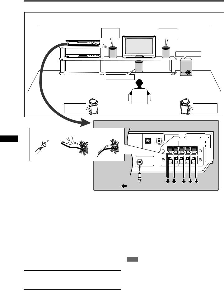
Connecting the speakers |
|
|
|
|
||
Speaker Layout Diagram |
|
|
|
|
|
|
|
|
Left front |
Right front |
|
|
|
|
|
speaker (L) |
speaker (R) |
|
|
|
|
|
|
Subwoofer (SW) |
|
||
|
|
Center speaker (C) |
|
|
|
|
|
Left surround |
|
|
|
Right surround |
|
|
speaker (LS) |
|
|
|
speaker (RS) |
|
1 |
2 |
3 |
|
|
CAUTION: SPEAKER |
|
|
2 |
1 |
|
|
IMPEDANCE 6 |
~ 16 |
|
FRONT |
CENTER |
SURROUND |
|
||
startedGetting |
|
|
SPEAKERS |
|||
|
|
RIGHT LEFT |
|
RIGHT LEFT |
||
|
|
|
|
|||
SW |
|
R L C RS LS |
|
Connecting the front, center, and surround speakers
Turn off all components before making connections.
1Twist and remove the insulation at the end of each speaker cord.
2Press and hold the clamp of the speaker terminal (1), then insert the speaker cord (2).
•For each speaker, connect the (+) and (–) terminals on the rear panel to the (+) and (–) terminals marked on the speakers.
3Release the finger from the clamp.
CAUTIONS:
•Use speakers with the SPEAKER IMPEDANCE indicated by the speaker terminals (6 Ω – 16 Ω).
•DO NOT connect more than one speaker to one speaker terminal.
Connecting the subwoofer
By connecting a subwoofer, you can enhance the bass or reproduce the original LFE signals recorded in digital software.
Connect the input jack of a powered subwoofer to the SUBWOOFER OUT jack on the rear panel, using a cord with RCA pin plugs (not supplied).
• Refer also to the manual supplied with your subwoofer.
After connecting all the speakers and/or a subwoofer, set the speaker setting information properly to obtain the best possible surround effect. For details, see pages 14 to 17.
NOTE
You can place a subwoofer wherever you like since bass sound is non-directional. Normally place it in front of you.
6

Connecting video components
SCART connection
You can enjoy pictures and sounds from playback components simply by connecting with the SCART cable.
•If your video components have digital output terminal, also connect them using the digital terminals explained in “Digital connection” (see page 9). By using these terminals, you can get better sound quality.
CAUTION:
If you connect a sound-enhancing device such as a graphic equalizer between the source components and this receiver, the sound output through this receiver may be distorted.
DO NOT use a TV through a VCR or a TV with a built-in VCR; otherwise, the picture may be distorted.
Turn off all components before making connections.
•Illustrations of the input/output terminals are typical examples. When you connect other components, refer also to their manuals since the terminal names actually printed on the rear vary among different components.
AV IN/OUT
TV
DVR/DVD |
VCR |
SCART cable (supplied: 1 cable)
NOTE
When the TV is equipped with multiple SCART terminals, refer to the TV manual to check the available video signals for each terminal, then connect the SCART cable correctly.
TV
Getting started
VCR
DVD recorder or DVD player
SCART Terminal Specifications
|
|
|
Terminal name |
*1 |
||
|
|
|
*2 |
|||
|
|
TV |
|
VCR |
DVR/DVD |
|
|
|
|
|
|||
Audio |
L/R |
|
|
|
|
*3 |
Input |
Composite |
|
|
|
|
|
|
− |
|
|
|
|
|
Video |
S-video (Y/C) |
|
|
|
|
|
|
RGB |
− |
|
|
|
|
Audio |
L/R |
*1 |
|
|
|
*4 |
Output |
Composite |
*2*3 |
*2*3 |
*2*3 |
|
|
|
|
|
− |
− |
|
|
Video |
S-video (Y/C) |
*3 |
|
|
||
|
RGB |
*3 |
|
− |
− |
|
T-V LINK |
|
*4 |
|
*4 |
*4 |
|
|
|
: Available |
–: Not available |
|
||
Only when TV Direct is in use (see page 12).
The signals input from a SCART terminal cannot be output through the same SCART terminal.
The video format of the output video signals are consistent with that of the input video signals. For example, if S-video signals are input to this receiver, no signals other than S- video signals can be output from this receiver.
Refer to the manuals supplied with the video components to check the setting of the input/output video signals.
The signals for the T-V LINK function are always going through the receiver.
CONTINUED ON THE NEXT PAGE
7
Getting started
For TV and video format
This receiver cannot convert the video signals. When the video signal of one video component is different from that of the other
(for example, one is S-video, the other is Composite), you may not see the pictures appropriately. In this case, unify the video signals of all the video components, or you need to switch the video signal of TV each time you change the source.
For an analogue decoder
To watch through or to record a scrambled program on your VCR, connect the analogue decoder to your VCR and select the scrambled channel on your VCR.
If there is not an appropriate terminal for the decoder connection on your VCR, connect the decoder to your TV. Refer also to the manuals supplied with these components.
For T-V LINK
•You can use the T-V LINK function if you connect a T-V LINK compatible TV and VCR to this receiver with a fully wired
SCART cables. For details on T-V LINK, refer also to the manuals supplied with the TV and the VCR.
•Connect a SCART cable to EXT-2 terminal on the JVC’s T-V
LINK compatible TV for the T-V LINK function.
•Some video components support the data communication like T-V LINK. For complete details, refer also to the manuals supplied with these components.
Audio/video connection
In addition to the SCART terminals, this receiver is equipped with the following video terminals:
•Component video input/output: DVR/DVD IN, MONITOR OUT
•Composite video input: VIDEO IN
NOTE
When recording the sounds and pictures onto the DVD recorder or VCR, record them through the SCART terminals.
IMPORTANT
The component video signals from the COMPONENT VIDEO jacks are transmitted only through the MONITOR OUT jacks.
Therefore, if the TV is connected to the receiver through the
SCART terminal (TV) and a playing video component is connected to the receiver through the component video jacks (DVR/DVD IN), you cannot view the playback picture on the TV.
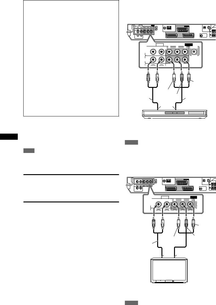
7Connecting a DVD recorder or DVD player to the DVR/DVD IN jacks
To fully enjoy Dolby Digital and DTS multi-channel software (including
Dual Mono software), connect the DVD recorder or DVD player through the digital input/output terminals (see page 9).
AUDIO |
|
|
|
VIDEO |
MONITOR |
Y |
PB |
PR |
VIDEO IN |
OUT |
|
|
|
|
VIDEO
DVR/DVD
IN
COMPONENT
Red |
White |
Red |
|
|
|
||
|
Green |
|
|
Stereo audio |
Blue |
Component video |
|
cable |
|
||
|
cable (not supplied) |
||
(not supplied) |
Å ı |
||
|
DVD recorder or DVD player
Å To left/right audio channel output
ı To component video output
NOTES
•Connect Y, PB, and PR correctly.
•Do not connect different components to the AUDIO DVR/DVD IN jacks and AV IN/OUT DVR/DVD terminal; otherwise, sounds from both components are come out of the speakers at the same time.
7 Connecting a TV to the MONITOR OUT jacks
AUDIO |
VIDEO |
MONITOR |
Y |
PB |
PR |
OUT |
|
|
|
Red |
White |
|
Stereo audio |
Green |
|
|
|
|
cable |
|
|
(not supplied) |
Å |
ı |
Å To left/right audio channel input ı To component video input
NOTES
Red
Blue
 Component video cable (not supplied)
TV
•Audio signals come out through the AUDIO MONITOR OUT (RIGHT/LEFT) jacks when TV Direct is in use (see page 12).
•Connect Y, PB, and PR correctly.
8
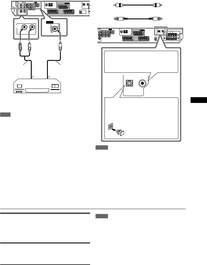
7Connecting a video component to the VIDEO IN jacks
You can connect a video component such as another VCR to the
VIDEO IN jacks using a composite video cable and stereo audio cable. Such component is referred to as the source “VIDEO” in this manual.
|
|
VIDEO |
VIDEO |
|
VIDEO IN |
|
|
|
IN |
|
|
RIGHT |
LEFT |
VIDEO |
|
|
Red |
White |
Yellow |
Digital connection
This receiver is equipped with two DIGITAL IN terminals—a digital coaxial terminal and digital optical terminal.
To reproduce the digital sound, use the digital connection in addition to the analogue connection methods described on pages
7 to 9.
Digital coaxial cable (supplied: 1 cable)
cable
When the component has a digital coaxial output terminal, connect it to the 1(DVR/DVD) terminal, using a digital coaxial cable (supplied).
Stereo audio cable |
|
|
Composite video |
|||||
(not supplied) |
Å |
|
ı cable (not supplied) |
|||||
|
|
|
|
|
||||
|
|
|
|
|
|
|
|
|
|
|
|
|
|
|
|
|
|
|
|
|
|
|
|
|
|
|
|
|
|
|
|
|
|
|
|
|
|
|
|
|
|
|
|
|
|
|
|
|
|
|
|
|
|
|
|
|
|
|
|
|
|
|
VCR , etc.
Å To left/right audio channel output ı To composite video output
NOTE
To view the picture, connect the TV to the receiver using the SCART cable.
DIGITAL IN
When the component has a digital optical output terminal, connect it to the 2(VIDEO) terminal, using a digital optical cable (not supplied).
Before connecting a digital optical cable, unplug the protective plug.
NOTES
•When shipped from the factory, the DIGITAL IN terminals have been set for use with the following components:
– 1(DVR/DVD): For DVD recorder or DVD player
– 2(VIDEO): |
For the component connected to the VIDEO |
|
IN jacks |
If you connect other components, change the digital input
(DIGITAL IN) terminal setting correctly. See “Setting the digital input (DIGITAL IN) terminals—DIGITAL IN1/2” on page 19.
•Select the correct digital input mode. See “Selecting the analogue or digital input mode” on page 10.
Getting started
Connecting the power cord
When all the audio/video connections have been made, connect the AC power plug to the wall outlet. Make sure that the plugs are inserted firmly. The standby lamp lights in red.
CAUTIONS:
•Do not touch the power cord with wet hands.
•Do not alter, twist or pull the power cord, or put anything heavy on it, which may cause fire, electric shock, or other accidents.
•If the cord is damaged, consult a dealer and have the power cord replaced with a new one.
NOTES
•Keep the power cord away from the connecting cables and the antenna. The power cord may cause noise or screen interference.
•The preset settings such as preset channels and sound adjustment may be erased in a few days in the following cases:
–When you unplug the power cord.
–When a power failure occurs.
9
Basic operations
Basic operations |
2 Select the source to play |
||||||
On the front panel: |
|
||||||
|
|
|
|||||
|
|
Turn SOURCE SELECTOR until the source name |
|||||
|
|
you want appears on the display. |
|||||
|
|
The source lamp corresponding to the selected source lights in |
|||||
|
|
red. |
|
|
|
|
|
|
|
• As you turn SOURCE SELECTOR, the source changes as |
|||||
|
|
|
follows: |
|
|
|
|
|
|
|
EQ C.TONE |
VIRTUAL SB AUDIO P. BASS |
TA NEWS INFO RDS TUNED ST AUTO MUTING SLEEP AUTO MODE |
||
|
|
|
LPCM |
L |
C R |
PL |
ATT |
1 |
2 |
3 |
DOLBY D S . WFR LFE |
NEO : 6 |
HP |
||
DTS AAC |
LS SB RS |
DSP 3D |
MHz |
||||
96 / 24 |
AUTO SR |
kHz |
|||||
|
|
|
DVR/DVD (DGT) |
VCR (DIGITAL) |
|||
|
|
|
VIDEO (DGTL) |
TV (DIGITAL) |
|||
|
|
|
FM |
|
AM |
(Back to the beginning) |
|
1 |
|
|
DVR/DVD (DGT)*: Select the DVD recorder or DVD player. |
||||
|
|
|
|||||
2 |
|
|
VCR (DIGITAL)*: |
Select the VCR. |
|||
|
|
VIDEO (DGTL)*: |
Select the component connected to the |
||||
|
When operating the receiver |
TV (DIGITAL)*: |
VIDEO IN jacks on the rear of the receiver. |
||||
|
using the remote control, set |
Select the TV. |
|||||
3 |
the mode selector to |
|
FM: |
|
|
Select an FM broadcast. |
|
“AUDIO/TV/VCR/STB.” |
|
AM: |
|
|
Select an AM (MW) broadcast. |
||
|
|
From the remote control: |
|||||
|
|
Press one of the source selecting buttons. |
|||||
|
|
• For the tuner, press FM/AM. Each time you press FM/AM, the |
|||||
|
|
|
band alternates between FM and AM (MW). |
||||
|
|
* Selecting the analogue or digital input mode |
|||||
|
|
For a component you have connected using both the analogue |
|||||
|
|
connection and the digital connection methods (see pages 7 to 9), |
|||||
|
|
you need to select the correct input mode. |
|||||
|
|
• |
You can select the digital input only for sources which you have |
||||
|
|
|
selected digital input terminals for. (See “Setting the digital input |
||||
|
|
|
(DIGITAL IN) terminals—DIGITAL IN1/2” on page 19.) |
||||
1 Turn on the power
Press  STANDBY/ON (or
  AUDIO on the remote control).
The standby lamp goes off and the source lamp of the current source lights in red.
Current source name appears.
|
|
|
|
|
|
|
|
|
|
EQ C.TONE |
VIRTUAL SB AUDIO P. BASS |
TA |
NEWS INFO RDS TUNED ST AUTO MUTING SLEEP AUTO MODE |
||||||
LPCM |
L |
C |
R |
|
PL |
|
ATT |
||
DOLBY D |
S . WFR LFE |
NEO : 6 |
|
HP |
|||||
DTS AAC |
|
|
|
|
|
DSP 3D |
|
MHz |
|
LS |
SB |
RS |
|||||||
96 / 24 |
AUTO SR |
|
kHz |
||||||
|
|
|
|
|
|
|
|
|
|
To turn off the power (into standby)
Press  STANDBY/ON (or
  AUDIO on the remote control) again.
The standby lamp lights in red.
NOTE
A small amount of power is consumed in standby mode. To turn the power off completely, unplug the AC power cord.
From the remote control ONLY:
Press SOUND, then press A/D INPUT to select the analogue or digital input mode.
•Each time you press A/D INPUT, the input mode alternates between the analogue input (“ANALOGUE”) and the digital input (“DGTL AUTO”).
DGTL AUTO: Select for the digital input mode. The receiver automatically detects the incoming signal format, then the digital signal format indicator (LPCM, DOLBY D, DTS, or DTS 96/24) for the detected signal lights up.
ANALOGUE: Select for the analogue input mode.
Initial setting: ANALOGUE
NOTE
After pressing SOUND, the numeric buttons work for sound adjustments. To use the numeric buttons to operate your target source, press the corresponding source selecting button before operation; otherwise, the remote control may not work as you intend.
10
Loading...