JVC KD-FX915R Manual

KS-FX915R
KS-FX815
Installation/Connection Manual РÛÍÓ‚Ó‰ÒÚ‚Ó ÔÓ ÛÒÚ‡ÌÓ‚ÍÂ/ ÔÓ‰Íβ˜ÂÌ˲
GET0018-002A
[EE]
ENGLISH
• This unit is designed to operate on 12 V DC, NEGATIVE ground electrical systems.
0101AOMCAPJES JVC EN, RU
РУССКИЙ
•ЭЪУ ЫТЪ УИТЪ‚У ‡Б ‡·УЪ‡МУ ‰Оя ˝НТФОЫ‡Ъ‡ˆЛЛ М‡ 12 В ФУТЪУяММУ„У М‡Ф яКВМЛя Т ПЛМЫТУП М‡ П‡ТТВ.
INSTALLATION (IN-DASH MOUNTING)
•The following illustration shows a typical installation. However, you should make adjustments corresponding to your specific car. If you have any questions or require information regarding installation kits, consult your JVC IN-CAR ENTERTAINMENT dealer or a company supplying kits.
УСТАНОВКА (УСТАНОВКА В ПРИБОРНУЮ ПАНЕЛЬ)
•Н‡ ТОВ‰Ы˛˘Лı ЛОО˛ТЪ ‡ˆЛяı ФУН‡Б‡М‡ ЪЛФУ‚‡я ЫТЪ‡МУ‚Н‡. ТВП МВ ПВМВВ, В˚ ‰УОКМ˚ Т‰ВО‡Ъ¸ ФУФ ‡‚НЛ ‚ ТУУЪ‚ВЪТЪ‚ЛЛ Т ЪЛФУП В‡¯В„У ‡‚ЪУПУ·ЛОя. ЕТОЛ Ы В‡Т ВТЪ¸ Н‡НЛВОЛ·У ‚УФ УТ˚, Н‡Т‡˛˘ЛВТя ЫТЪ‡МУ‚НЛ, У· ‡ЪЛЪВТ¸ Н В‡¯ВПЫ ‰ЛОВ Ы JVC IN-CAR ENTERTAINMENT ЛОЛ ‚ НУПФ‡МЛ˛, ФУТЪ‡‚Оя˛˘Ы˛ ТУУЪ‚ВЪТЪ‚Ы˛˘ЛВ Ф ЛМ‡‰ОВКМУТЪЛ.
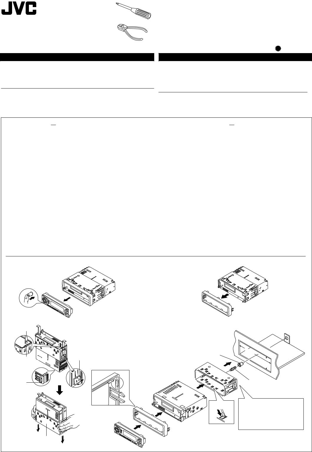
1Before mounting: Press 

 (Control Panel Release button) to detach the control panel if already attached.
* When shipped from the factory, the control panel is packed in the hard case.
2Remove the trim plate.
3Remove the sleeve after disengaging the sleeve locks.
1 Stand the unit.
Note: When you stand the unit, be careful not to damage the fuse on the rear.
2Insert the 2 handles between the unit and the sleeve, as illustrated, to disengage the sleeve locks.
3Remove the sleeve.
Note: Be sure to keep the handles for future use after installing the unit.
4Install the sleeve into the dashboard.
* After the sleeve is correctly installed into the dashboard, bend the appropriate tabs to hold the sleeve firmly in place, as illustrated.
5Fix the mounting bolt to the rear of the unit’s body and place the rubber cushion over the end of the bolt.
6Do the required electrical connections.
7Slide the unit into the sleeve until it is locked.
8Attach the trim plate so that the projection on the trim plate is fixed to the left side of the unit.
9Attach the control panel.
1П ‰ ÛÒÚ‡ÌÓ‚ÍÓÈ: Н‡КПЛЪВ НМУФНЫ 

 (НМУФН‡ УТ‚У·УК‰ВМЛя Ф‡МВОЛ ЫФ ‡‚ОВМЛя) ‰Оя УЪТУВ‰ЛМВМЛя Ф‡МВОЛ ЫФ ‡‚ОВМЛя.
* П Л ФУТЪ‡‚НВ Т Щ‡· ЛНЛ Ф‡МВО¸ЫФ ‡‚ОВМЛя ı ‡МЛЪТя ‚ КВТЪНУП ЩЫЪОя В.
2У‰‡ÎËÚ ‰ÂÍÓ ‡ÚË‚ÌÛ˛ Ô‡ÌÂθ.
3У‰‡ОЛЪВ ПЫЩЪЫ ФУТОВ УТ‚У·УК‰ВМЛя Б‡ФУ У‚ ПЫЩЪ˚.
1 УÒÚ‡ÌÓ‚ËÚ ÛÒÚ ÓÈÒÚ‚Ó.
П ËϘ‡ÌËÂ: УТЪ‡М‡‚ОЛ‚‡ИЪВ ЫТЪ УИТЪ‚У Ъ‡НЛП У· ‡БУП, ˜ЪУ·˚ МВ ФУ‚ В‰ЛЪ¸ Ф В‰Уı ‡МЛЪВО¸, ‡ТФУОУКВММ˚И ТБ‡‰Л.
2 ВТЪ‡‚¸ЪВ ‰‚‡ ˚˜‡„‡ ПВК‰Ы ЫТЪ УИТЪ‚УП Л ПЫЩЪУИ, Н‡Н ФУН‡Б‡МУ М‡ ЛТЫМНВ, ‰Оя УТ‚У·УК‰ВМЛя Б‡ФУ У‚ ПЫЩЪ˚.
3У‰‡ОЛЪВ ПЫЩЪЫ.
П ËϘ‡ÌËÂ: ПУТОВ ЫТЪ‡МУ‚НЛ ЫТЪ УИТЪ‚‡ ТУı ‡МЛЪВ ˚˜‡„Л ‰Оя ЛТФУО¸БУ‚‡МЛя ‚ ·Ы‰Ы˘ВП.
4УТЪ‡МУ‚ЛЪВ ПЫЩЪЫ ‚ Ф Л·У МЫ˛ Ф‡МВО¸.
* ПУТОВ ЫТЪ‡МУ‚НЛ ПЫЩЪ˚ ‚ Ф Л·У МЫ˛ Ф‡МВО¸ ТУ„МЛЪВ ТУУЪ‚ВЪТЪ‚Ы˛˘ЛВ БЫ·ˆ˚ ‰Оя ЩЛНТ‡ˆЛЛ ПЫЩЪ˚, Н‡Н ФУН‡Б‡МУ М‡ ЛТЫМНВ.
5З‡ЪяМЛЪВ ЩЛНТЛ Ы˛˘ЛИ ·УОЪ М‡ Б‡‰МВИ ˜‡ТЪЛ НУ ФЫТ‡ ЫТЪ УИТЪ‚‡ Л М‡‰ВМ¸ЪВВБЛМУ‚˚И ˜ВıУО М‡ НУМВˆ ·УОЪ‡.
6В˚ФУОМЛЪВ МВУ·ıУ‰ЛП˚В ФУ‰НО˛˜ВМЛя НУМЪ‡НЪУ‚, Н‡Н ФУН‡Б‡МУ М‡ У·У УЪМУИ ТЪУ УМВ ˝ЪУИ ЛМТЪ ЫНˆЛЛ.
7З‡‰‚ЛМ¸ЪВ ЫТЪ УИТЪ‚У ‚ ПЫЩЪЫ ‰У ЫФУ ‡.
8П ЛН ВФЛЪВ ‰ВНУ ‡ЪЛ‚МЫ˛ Ф‡МВО¸ Ъ‡НЛП У· ‡БУП, ˜ЪУ·˚ ‚˚ТЪЫФ М‡ ‰ВНУ ‡ЪЛ‚МУИ Ф‡МВОЛ ‚У¯ВО ‚ ОВ‚Ы˛ ˜‡ТЪ¸ ЫТЪ УИТЪ‚‡.
9П ЛН ВФЛЪВ Ф‡МВО¸ ЫФ ‡‚ОВМЛя.
1 |
2 |
Trim plate П Ë·Ó Ì‡я Ô‡ÌÂθ
Control panel П‡ÌÂθ ÛÔ ‡‚ÎÂÌËя
3 HandleР˚˜‡„
Lock Plate
Slot  ФËÍÒË Û˛˘‡я Ô‡ÌÂθ ОÚ‚Â ÒÚËÂ
Dashboard П Ë·Ó Ì‡я Ô‡ÌÂθ
|
Rubber cushion |
184 |
|
|
|
|
РВБЛМУ‚˚И ˜ВıУО |
mm |
|
|
|
|
|
|
|
|
|
Sleeve |
4 |
|
|
53 |
mm |
5 |
|
||||
|
|
||||
МÛÙÚ‡ |
|
|
|
||
|
|
|
|
|
|
Fuse |
|
|
7 |
Mounting bolt |
|
|
|
||
П В‰Уı ‡МЛЪВО¸ |
|
|
|
К ВФВКМ˚И ·УОЪ |
|
|
8 |
4* |
6 |
|
|
|
See “ELECTRICAL CONNECTIONS”. |
|
|
|
9 |
|
СÏ. “ЭЛЕКТРИЧЕСКИЕ |
|
|
|
ПОДКЛЮЧЕНИЯ.” |
|
|
|
|
|
|
|
|
|
Trim plate |
|
|
|
|
ДÂÍÓ ‡Ú˂̇я Ô‡ÌÂθ |
|
|
Sleeve |
Control panel |
|
|
|
МÛÙÚ‡ |
|
|
|
|
П‡ÌÂθ |
|
|
|
|
|
|
|
|
|
|
ÛÔ ‡‚ÎÂÌËя |
|
|

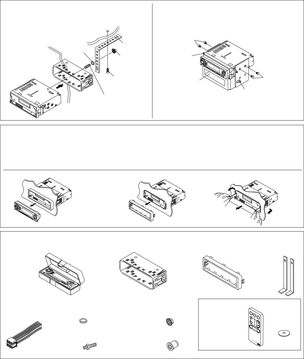
•When using the optional stay
•П Л ЛТФУО¸БУ‚‡МЛЛ ‰УФУОМЛЪВО¸МУИ ТЪУИНЛ
|
|
Fire wall |
|
|
СÚÂ̇ |
|
Washer |
Stay (option) |
|
СÚÓÈ͇ |
|
|
Ш‡È·‡ |
|
|
(‰УФУОМЛЪВО¸МУ) |
|
|
|
|
Dashboard |
|
Lock nut |
ДÂÍÓ ‡Ú˂̇я Ô‡ÌÂθ |
|
ФËÍÒË Û˛˘‡я |
|
|
„‡È͇ |
|
|
Screw (option) |
|
|
ВЛМЪ (‰УФУОМЛЪВО¸МУ) |
|
Sleeve |
Mounting bolt |
|
МÛÙÚ‡ |
|
|
К ВФВКМ˚И ·УОЪ |
|
|
|
•When installing the unit without using the sleeve
•П Л ЫТЪ‡МУ‚НВ ЫТЪ УИТЪ‚‡ ·ВБ ЛТФУО¸БУ‚‡МЛя ПЫЩЪ˚
In a Toyota for example, first remove the car radio and install the unit in its place.
В ТУИУЪВ, М‡Ф ЛПВ , ТМ‡˜‡О‡ Ы‰‡ОЛЪВ ‡‚ЪУПУ·ЛО¸МЫ˛ П‡„МЛЪУОЫ, Б‡ЪВП ЫТЪ‡МУ‚ЛЪВ М‡ ВВ ПВТЪУ ˝ЪУ ЫТЪ УИТЪ‚У.
Flat type screws (M5 x 6 mm)*
К ВФВКМ˚В ‚ЛМЪ˚ (М5 ı 6 ПП)* * Not included with this unit. * НВ ‚ıУ‰яЪ ‚ НУПФОВНЪ.
Bracket* К Ó̯ÚÂÈÌ*
Flat type screws (M5 x 6 mm)* |
|
К‡ Ï‡Ì |
К ВФВКМ˚В ‚ЛМЪ˚ (М5 ı 6 ПП)* |
|
Bracket* |
|
К Ó̯ÚÂÈÌ* |
П ËϘ‡ÌËÂ: П Л ЫТЪ‡МУ‚НВ ЫТЪ УИТЪ‚‡ М‡ Н ВФВКМ˚И Н УМ¯ЪВИМ, ЛТФУО¸БЫИЪВ ЪУО¸НУ ‚ЛМЪ˚ ‰ОЛМУИ 6 ПП. П Л ЛТФУО¸БУ‚‡МЛЛ ·УОВВ ‰ОЛММ˚ı ‚ЛМЪУ‚, ПУКМУ ФУ‚ В‰ЛЪ¸ ЫТЪ УИТЪ‚У.
Removing the unit
• Before removing the unit, release the rear section.
1Remove the control panel.
2Remove the trim plate.
3Insert the 2 handles into the slots, as shown. Then, while gently pulling the handles away from each other, slide out the unit. (Be sure to keep the handles after installing it.)
У‰‡ОВМЛВ ЫТЪ УИТЪ‚‡
• ПВ В‰ Ы‰‡ОВМЛВП ЫТЪ УИТЪ‚‡ УТ‚У·У‰ЛЪВ Б‡‰М˛˛ ˜‡ТЪ¸.
1У‰‡ÎËÚ ԇÌÂθ ÛÔ ‡‚ÎÂÌËя.
2У‰‡ÎËÚ ‰ÂÍÓ ‡ÚË‚ÌÛ˛ Ô‡ÌÂθ.
3ВÒÚ‡‚¸Ú 2 ˚˜‡„‡ ‚ ÓÚ‚Â ÒÚËя, Í‡Í ÔÓ͇Á‡ÌÓ Ì‡ ËÎβÒÚ ‡ˆËË. З‡ÚÂÏ, Ô·‚ÌÓ ‡Á‰‚Ë„‡я˚˜‡„Ë ‚ ÒÚÓ ÓÌ˚, ‚˚̸Ú ÛÒÚ ÓÈÒÚ‚Ó. (ПÓÒΠÛÒÚ‡ÌÓ‚ÍËя ÒÓı ‡ÌËÚ ˚˜‡„Ë.)
1 |
2 |
3 |
Handle Р˚˜‡„
|
Trim plate |
Control Panel |
П Ë·Ó Ì‡я Ô‡ÌÂθ |
П‡ÌÂθ ÛÔ ‡‚ÎÂÌËя |
|
Parts list for installation and connection
The following parts are provided with this unit.
After checking them, please set them correctly.
Hard case/Control Panel |
Sleeve |
ЖВТЪНЛИ ЩЫЪОя / |
МÛÙÚ‡ |
П‡ÌÂθ ÛÔ ‡‚ÎÂÌËя |
|
Washer (ø5) Power cord Ш‡È·‡ (ø5) ШÌÛ ÔËÚ‡ÌËя
Mounting bolt (M5 x 20 mm) К ВФВКМ˚И ·УОЪ (M5 x 20 ПП)
СФЛТУН ‰ВЪ‡ОВИ ‰Оя ЫТЪ‡МУ‚НЛ Л ФУ‰НО˛˜ВМЛя
СОВ‰Ы˛˘ЛВ ‰ВЪ‡ОЛ ФУТЪ‡‚ОВМ˚ ‚ НУПФОВНЪВ Т ЫТЪ УИТЪ‚УП.
ПУТОВ Ф У‚В НЛ НУПФОВНЪ‡ˆЛЛ, ФУК‡ОЫИТЪ‡, ЫТЪ‡МУ‚ЛЪВ Лı Ф ‡‚ЛО¸МУ.
Trim plate |
Handles |
П Ë·Ó Ì‡я Ô‡ÌÂθ |
Р˚˜‡„Ë |
|
ТОЛЬКО ДЛЯ KS-FX915R |
|
Lock nut (M5) |
|
|
ФËÍÒË Û˛˘‡я „‡È͇ (М5) |
|
Battery |
|
|
|
|
Remote controller |
Б‡Ú‡ Âя |
|
|
|
|
ДЛТЪ‡МˆЛУММУВ |
|
|
ЫФ ‡‚ОВМЛВ |
|
Rubber cushion |
|
|
РВБЛМУ‚˚И ˜ВıУО |
|
CR2025 |
|
|
TROUBLESHOOTING |
|
BЫЯВЛЕНИЕ НЕИСПРАВНОСТЕЙ |
|
|
|
|
|
• The fuse blows.
* Are the red and black leads connected correctly?
•Power cannot be turned on.
* Is the yellow lead connected?
•No sound from the speakers.
* Is the speaker output lead short-circuited?
• Sound is distorted.
*Is the speaker output lead grounded?
*Are the “–” terminals of L and R speakers grounded in common?
• Unit becomes hot.
*Is the speaker output lead grounded?
*Are the “–” terminals of L and R speakers grounded in common?
• С ‡·УЪ‡О Ф В‰Уı ‡МЛЪВО¸.
* П ‡‚ËθÌÓ ÎË ÔÓ‰Íβ˜ÂÌ˚ ˜Â Ì˚È Ë Í ‡ÒÌ˚È Ô Ó‚Ó‰‡?
• ПËÚ‡ÌË Ì ‚Íβ˜‡ÂÚÒя.
* ПÓ‰Íβ˜ÂÌ ÎË ÊÂÎÚ˚È Ô Ó‚Ó‰?
• З‚ЫН МВ ‚˚‚У‰ЛЪТя ˜В ВБ „ УПНУ„У‚У ЛЪВОЛ.
* НВЪ ОЛ НУ УЪНУ„У Б‡П˚Н‡МЛя М‡ Н‡·ВОВ ‚˚ıУ‰‡ „ УПНУ„У‚У ЛЪВОВИ?
• З‚ÛÍ ËÒ͇ÊÂÌ.
*З‡БВПОВМ ОЛ Ф У‚У‰ ‚˚ıУ‰‡ „ УПНУ„У‚У ЛЪВОВИ?
*З‡БВПОВМ˚ ОЛ ‡Б˙ВП˚ “–” ОВ‚У„У (L) Л Ф ‡‚У„У (R) „ УПНУ„У‚У ЛЪВОВИ?
• УÒÚ ÓÈÒÚ‚Ó Ì‡„ ‚‡ÂÚÒя.
*З‡БВПОВМ ОЛ Ф У‚У‰ ‚˚ıУ‰‡ „ УПНУ„У‚У ЛЪВОВИ?
*З‡БВПОВМ˚ ОЛ ‡Б˙ВП˚ “–” ОВ‚У„У (L) Л Ф ‡‚У„У (R) „ УПНУ„У‚У ЛЪВОВИ?
 Loading...