

JLG 80HX-HX-6 Operator Manual

Operation and Safety Manual
Model
80HX
80HX+6
P/N - 3120890
August 21, 2007

FOREWORD
f
FOREWORD
The purpose of this manual is to provide users with the operating procedures essential for the promotion o
proper machine operation for its intended purpose. It is important to over-stress proper machine usage. All
information in this manual should be READ and UNDERSTOOD before any attempt is made to operate the
machine. YOUR OPERATING MANUAL IS YOUR MOST IMPORTANT TOOL - Keep it with the machine.
REMEMBER ANY EQUIPMENT IS ONLY AS SAFE AS THE OPERATOR.
BECAUSE THE MANUFACTURER HAS NO DIRECT CONTROL OVER MACHINE APPLICATION AND
OPERATION, PROPER SAFETY PRACTICES ARE THE RESPONSIBILITY OF THE USER AND HIS OPERATING PERSONNEL.
ALL INSTRUCTIONS IN THIS MANUAL ARE BASED ON THE USE OF THE MACHINE UNDER PROPER
OPERATING CONDITIONS, WITH NO DEVIATIONS FROM THE ORIGINAL DESIGN. ALTERATION AND/OR
MODIFICATION OF THE MACHINE IS STRICTLY FORBIDDEN, WITHOUT WRITTEN APPROVAL FROM
JLG INDUSTRIES, PER OSHA REGULATIONS AND APPLICABLE ANSI STANDARDS.
THIS SAFETY ALERT SYMBOL IS USED TO CALL ATTENTION TO POTENTIAL HAZARDS WHICH
MAY LEAD TO SERIOUS INJURY OR DEATH IF IGNORED.
Safety of personnel and proper use of the machine are of primary concern, DANGER, WARNING, CAUTION, IMPORTANT, INSTRUCTIONS and NOTE are inserted throughout this manual to emphasize these
areas. They are defined as follows:
DANGER INDICATES AN IMMINENTLY HAZARDOUS SITUATION
WHICH, IF NOT AVOIDED WILL RESULT IN SERIOUS INJURY OR
DEATH.]
CAUTION INDICATES A POTENTIALLY HAZARDOUS SITUATION
WHICH, IF NOT AVOIDED, MAY RESULT IN MINOR OR MODERATE
INJURY. IT MAY ALSO BE USED TO ALERT AGAINST UNSAFE
PRACTICES
WARNING INDICATES A POTENTIALLY HAZARDOUS SITUATION
WHICH, IF NOT AVOIDED COULD RESULT IN SERIOUS INJURY
OR DEATH.
IMPORTANT OR INSTRUCTIONS INDICATES A PROCEDURES
ESSENTIAL FOR SAFE OPERATION AND WHICH, IF NOT FOLLOWED, MAY RESULT IN A MALFUNCTION OR DAMAGE TO THE
MACHINE.
JLG INDUSTRIES MAY HAVE ISSUED SAFETY RELATED BULLETINS FOR YOUR JLG PRODUCT. CONTACT JLG INDUSTRIES INC.
OR THE LOCAL AUTHORIZED JLG DISTRIBUTOR FOR INFORMATION CONCERNING SAFETY RELATED BULLETINS WHICH MAY
HAVE BEEN ISSUED FOR YOUR JLG PRODUCT. ALL ITEMS REQUIRED BY THE SAFETY RELATED BULLETINS MUST BE COMPLETED ON THE AFFECTED JLG PRODUCT
Due to continuous product improvements, JLG Industries, Inc. reserves the right to make specification changes without prior notification. Contact JLG Industries, Inc. for updated information.
3120890 – JLG Lift – a

FOREWORD
This page left blank intentionally.
b – JLG Lift – 3120890

FOREWORD
All procedures herein are based on the use of the
machine under proper operating conditions, with no
deviations from original design intent... as per OSHA
regulations.
READ & HEED!
The ownership, use, service, and/or maintenance of
this machine is subject to various governmental and
local laws and regulations. It is the responsibility of
the owner/user to be knowledgeable of these laws
and regulations and to comply with them. The most
prevalent regulations of this type in the United States
are the Federal OSHA Safety Regulations*. Listed
below, in abbreviated form are some of the requirements of Federal OSHA regulations in effect as of the
date of publication of this handbook.
The listing of these requirements shall not relieve
the owner/user of the responsibility and obligation
to determine all applicable laws and regulations and
their exact wording and requirements, and to comply with the requirements. Nor shall the listing of
these requirements constitute an assumption of
responsibility of liability on the part of JLG Industries, Inc.
1. Only trained and authorized operators shall be
permitted to operate the aerial lift.
2. A malfunctioning lift shall be shut down until
repaired.
5. All personnel in the platform shall, at all times,
wear approved fall protection devices and
other safety gear as required.
6. Load limits specified by the manufacturer shall
not be exceeded.
7. Instruction and warning placards must be legible.
8. Aerial lifts may be field modified for uses other
than those intended by the manufacturer only if
certified in writing by the manufacturer to be in
conformity to JLG requirements and to be at
least as safe as it was prior to modification.
9. Aerial lifts shall not be used near electric power
lines unless the lines have been de energized
or adequate clearance is maintained.
10. Employees using aerial lifts shall be instructed
on how to recognize and avoid unsafe conditions and hazards.
11. Ground controls shall not be operated unless
permission has been obtained from personnel
in the platform, except in case of an emergency.
12. Regular inspection of the job site and aerial lift
shall be performed by competent persons.
13. Personnel shall always stand on the floor of the
platform, not on boxes, planks, railing or other
devices, for a work position.
*Applicable Federal OSHA regulations for the
United States, as of the date of publication of this
manual, include, but are not limited to, 29 CFR
1910.67, 29 CFR 1926.20, 29 CFR 1926.21, 29 CFR
1926.28, and 29 CFR 1926.453.
3. The controls shall be plainly marked as to their
function.
4. The controls shall be tested each day prior to
use to determine that they are in safe operating
condition.
3120890 – JLG Lift – c

FOREWORD
REVISON LOG
Original Issue - May 1, 1999
Revised - August 21, 2007
d – JLG Lift – 3120890

SECTION - FOREWORD
SECTION 1 - SAFETY PRECAUTIONS
1.1 General . . . . . . . . . . . . . . . . . . . . . . . . . . . . . . . . . . . . . . . . . . . . . . . . . . . . . . . . . . . . . . . . . . . . . . 1-1
1.2 Driving/Towing. . . . . . . . . . . . . . . . . . . . . . . . . . . . . . . . . . . . . . . . . . . . . . . . . . . . . . . . . . . . . . . . . 1-1
1.3 Electrocution Hazard. . . . . . . . . . . . . . . . . . . . . . . . . . . . . . . . . . . . . . . . . . . . . . . . . . . . . . . . . . . .1-2
1.4 Pre-Operational . . . . . . . . . . . . . . . . . . . . . . . . . . . . . . . . . . . . . . . . . . . . . . . . . . . . . . . . . . . . . . . .1-2
1.5 Driving . . . . . . . . . . . . . . . . . . . . . . . . . . . . . . . . . . . . . . . . . . . . . . . . . . . . . . . . . . . . . . . . . . . . . . . 1-4
1.6 Operation. . . . . . . . . . . . . . . . . . . . . . . . . . . . . . . . . . . . . . . . . . . . . . . . . . . . . . . . . . . . . . . . . . . . .1-5
1.7 Towing and Hauling . . . . . . . . . . . . . . . . . . . . . . . . . . . . . . . . . . . . . . . . . . . . . . . . . . . . . . . . . . . .1-8
SECTION 2 - PREPARATION AND INSPECTION
2.1 General . . . . . . . . . . . . . . . . . . . . . . . . . . . . . . . . . . . . . . . . . . . . . . . . . . . . . . . . . . . . . . . . . . . . . . 2-1
2.2 Preparation For Use . . . . . . . . . . . . . . . . . . . . . . . . . . . . . . . . . . . . . . . . . . . . . . . . . . . . . . . . . . . .2-1
2.3 Delivery and Frequent Inspection . . . . . . . . . . . . . . . . . . . . . . . . . . . . . . . . . . . . . . . . . . . . . . . . . . 2-1
Chassis. . . . . . . . . . . . . . . . . . . . . . . . . . . . . . . . . . . . . . . . . . . . . . . . . . . . . . . . . . . . . . . . . . 2-1
Turntable . . . . . . . . . . . . . . . . . . . . . . . . . . . . . . . . . . . . . . . . . . . . . . . . . . . . . . . . . . . . . . . . 2-2
Boom . . . . . . . . . . . . . . . . . . . . . . . . . . . . . . . . . . . . . . . . . . . . . . . . . . . . . . . . . . . . . . . . . . . 2-2
Extend-A-Reach (If Equipped). . . . . . . . . . . . . . . . . . . . . . . . . . . . . . . . . . . . . . . . . . . . . . . . 2-4
Platform. . . . . . . . . . . . . . . . . . . . . . . . . . . . . . . . . . . . . . . . . . . . . . . . . . . . . . . . . . . . . . . . . 2-4
Torque Requirements . . . . . . . . . . . . . . . . . . . . . . . . . . . . . . . . . . . . . . . . . . . . . . . . . . . . . . 2-4
2.4 Daily Walk-Around Inspection. . . . . . . . . . . . . . . . . . . . . . . . . . . . . . . . . . . . . . . . . . . . . . . . . . . . . 2-4
GENERAL. . . . . . . . . . . . . . . . . . . . . . . . . . . . . . . . . . . . . . . . . . . . . . . . . . . . . . . . . . . . . . . . 2-7
2.5 Daily Functional Check . . . . . . . . . . . . . . . . . . . . . . . . . . . . . . . . . . . . . . . . . . . . . . . . . . . . . . . . . .2-10
2.6 Torque Requirements . . . . . . . . . . . . . . . . . . . . . . . . . . . . . . . . . . . . . . . . . . . . . . . . . . . . . . . . . . . 2-12
2.7 Battery Maintenance . . . . . . . . . . . . . . . . . . . . . . . . . . . . . . . . . . . . . . . . . . . . . . . . . . . . . . . . . . . .2-12
Battery Maintenance . . . . . . . . . . . . . . . . . . . . . . . . . . . . . . . . . . . . . . . . . . . . . . . . . . . . . . . 2-12
2.8 Lubrication. . . . . . . . . . . . . . . . . . . . . . . . . . . . . . . . . . . . . . . . . . . . . . . . . . . . . . . . . . . . . . . . . . . . 2-12
TABLE OF CONTENTS
SECTION 3 - USER RESPONSIBILITIES AND MACHINE CONTROL
3.1 General . . . . . . . . . . . . . . . . . . . . . . . . . . . . . . . . . . . . . . . . . . . . . . . . . . . . . . . . . . . . . . . . . . . . . . 3-1
3.2 Personnel Training . . . . . . . . . . . . . . . . . . . . . . . . . . . . . . . . . . . . . . . . . . . . . . . . . . . . . . . . . . . . .3-1
Operator Training. . . . . . . . . . . . . . . . . . . . . . . . . . . . . . . . . . . . . . . . . . . . . . . . . . . . . . . . . . 3-1
Training Supervision . . . . . . . . . . . . . . . . . . . . . . . . . . . . . . . . . . . . . . . . . . . . . . . . . . . . . . . 3-1
Operator Responsibility . . . . . . . . . . . . . . . . . . . . . . . . . . . . . . . . . . . . . . . . . . . . . . . . . . . . . 3-1
3.3 Operating Characteristics and Limitations . . . . . . . . . . . . . . . . . . . . . . . . . . . . . . . . . . . . . . . . . . .3-2
General. . . . . . . . . . . . . . . . . . . . . . . . . . . . . . . . . . . . . . . . . . . . . . . . . . . . . . . . . . . . . . . . . . 3-2
Placards . . . . . . . . . . . . . . . . . . . . . . . . . . . . . . . . . . . . . . . . . . . . . . . . . . . . . . . . . . . . . . . . . 3-2
Capacities . . . . . . . . . . . . . . . . . . . . . . . . . . . . . . . . . . . . . . . . . . . . . . . . . . . . . . . . . . . . . . . 3-2
Stability. . . . . . . . . . . . . . . . . . . . . . . . . . . . . . . . . . . . . . . . . . . . . . . . . . . . . . . . . . . . . . . . . . 3-2
3.4 Controls and Indicators. . . . . . . . . . . . . . . . . . . . . . . . . . . . . . . . . . . . . . . . . . . . . . . . . . . . . . . . . .3-5
Ground Controls . . . . . . . . . . . . . . . . . . . . . . . . . . . . . . . . . . . . . . . . . . . . . . . . . . . . . . . . . . 3-5
Platform Station - May 1994 to Present . . . . . . . . . . . . . . . . . . . . . . . . . . . . . . . . . . . . . . . . . 3-10
Platform Station - September 1991 to May 1994 . . . . . . . . . . . . . . . . . . . . . . . . . . . . . . . . . 3-14
Platform Station - Hydraulic Controls . . . . . . . . . . . . . . . . . . . . . . . . . . . . . . . . . . . . . . . . . . 3-18
Steer/Axle Selector Valve. . . . . . . . . . . . . . . . . . . . . . . . . . . . . . . . . . . . . . . . . . . . . . . . . . . . 3-22
SECTION 4 - MACHINE OPERATION
4.1 Description . . . . . . . . . . . . . . . . . . . . . . . . . . . . . . . . . . . . . . . . . . . . . . . . . . . . . . . . . . . . . . . . . . .4-1
4.2 General . . . . . . . . . . . . . . . . . . . . . . . . . . . . . . . . . . . . . . . . . . . . . . . . . . . . . . . . . . . . . . . . . . . . . . 4-1
4.3 Engine Operation . . . . . . . . . . . . . . . . . . . . . . . . . . . . . . . . . . . . . . . . . . . . . . . . . . . . . . . . . . . . . .4-2
Starting Procedure. . . . . . . . . . . . . . . . . . . . . . . . . . . . . . . . . . . . . . . . . . . . . . . . . . . . . . . . . 4-2
Shutdown Procedure. . . . . . . . . . . . . . . . . . . . . . . . . . . . . . . . . . . . . . . . . . . . . . . . . . . . . . . 4-2
4.4 Traveling (Driving) . . . . . . . . . . . . . . . . . . . . . . . . . . . . . . . . . . . . . . . . . . . . . . . . . . . . . . . . . . . . . . 4-2
Traveling Forward or Reverse . . . . . . . . . . . . . . . . . . . . . . . . . . . . . . . . . . . . . . . . . . . . . . . . 4-3
4.5 Steering . . . . . . . . . . . . . . . . . . . . . . . . . . . . . . . . . . . . . . . . . . . . . . . . . . . . . . . . . . . . . . . . . . . . . .4-3
4.6 Parking and Stowing . . . . . . . . . . . . . . . . . . . . . . . . . . . . . . . . . . . . . . . . . . . . . . . . . . . . . . . . . . . .4-3
3120890 – JLG Lift – i

TABLE OF CONTENTS (Continued)
4.7 Platform . . . . . . . . . . . . . . . . . . . . . . . . . . . . . . . . . . . . . . . . . . . . . . . . . . . . . . . . . . . . . . . . . . . . . .4-3
Loading From Ground Level . . . . . . . . . . . . . . . . . . . . . . . . . . . . . . . . . . . . . . . . . . . . . . . . . 4-3
Loading From Positions Above Ground
Level 4-4
Platform Level Adjustment. . . . . . . . . . . . . . . . . . . . . . . . . . . . . . . . . . . . . . . . . . . . . . . . . . . 4-4
Platform Rotation . . . . . . . . . . . . . . . . . . . . . . . . . . . . . . . . . . . . . . . . . . . . . . . . . . . . . . . . . . 4-4
4.8 Boom . . . . . . . . . . . . . . . . . . . . . . . . . . . . . . . . . . . . . . . . . . . . . . . . . . . . . . . . . . . . . . . . . . . . . . . . 4-5
Swinging the Boom . . . . . . . . . . . . . . . . . . . . . . . . . . . . . . . . . . . . . . . . . . . . . . . . . . . . . . . . 4-5
Raising and Lowering the Main Boom . . . . . . . . . . . . . . . . . . . . . . . . . . . . . . . . . . . . . . . . . 4-5
Telescoping the Main Boom . . . . . . . . . . . . . . . . . . . . . . . . . . . . . . . . . . . . . . . . . . . . . . . . . 4-5
4.9 Shut Down and Park . . . . . . . . . . . . . . . . . . . . . . . . . . . . . . . . . . . . . . . . . . . . . . . . . . . . . . . . . . . .4-5
4.10 Tie Down and Lifting . . . . . . . . . . . . . . . . . . . . . . . . . . . . . . . . . . . . . . . . . . . . . . . . . . . . . . . . . . . . 4-6
4.11 Axles, Extending and Retracting . . . . . . . . . . . . . . . . . . . . . . . . . . . . . . . . . . . . . . . . . . . . . . . . . . . 4-6
Machines Without Jacks . . . . . . . . . . . . . . . . . . . . . . . . . . . . . . . . . . . . . . . . . . . . . . . . . . . . 4-6
Machines With Jacks . . . . . . . . . . . . . . . . . . . . . . . . . . . . . . . . . . . . . . . . . . . . . . . . . . . . . . . 4-8
4.12 Oscillating Axle Lockout Test (If Equipped). . . . . . . . . . . . . . . . . . . . . . . . . . . . . . . . . . . . . . . . . .4-9
4.13 Steer/tow Selector (If Equipped). . . . . . . . . . . . . . . . . . . . . . . . . . . . . . . . . . . . . . . . . . . . . . . . . . . 4-10
4.14 Towing (If Equipped). . . . . . . . . . . . . . . . . . . . . . . . . . . . . . . . . . . . . . . . . . . . . . . . . . . . . . . . . . . . 4-10
Prior to towing the machine, complete the following:. . . . . . . . . . . . . . . . . . . . . . . . . . . . . . 4-10
After towing the machine, complete the following: . . . . . . . . . . . . . . . . . . . . . . . . . . . . . . . . 4-10
SECTION 5 - OPTIONAL EQUIPMENT
5.1 Rotator . . . . . . . . . . . . . . . . . . . . . . . . . . . . . . . . . . . . . . . . . . . . . . . . . . . . . . . . . . . . . . . . . . . . . . . 5-1
5.2 Dual Fuel System (Gas Engine Only) . . . . . . . . . . . . . . . . . . . . . . . . . . . . . . . . . . . . . . . . . . . . . . . 5-1
Description. . . . . . . . . . . . . . . . . . . . . . . . . . . . . . . . . . . . . . . . . . . . . . . . . . . . . . . . . . . . . . . 5-1
Changing From Gasoline to LP Gas . . . . . . . . . . . . . . . . . . . . . . . . . . . . . . . . . . . . . . . . . . . 5-1
Changing From LP Gas to Gasoline. . . . . . . . . . . . . . . . . . . . . . . . . . . . . . . . . . . . . . . . . . . 5-1
5.3 Oscillating Axle . . . . . . . . . . . . . . . . . . . . . . . . . . . . . . . . . . . . . . . . . . . . . . . . . . . . . . . . . . . . . . . .5-1
5.4 Tow Package. . . . . . . . . . . . . . . . . . . . . . . . . . . . . . . . . . . . . . . . . . . . . . . . . . . . . . . . . . . . . . . . . . 5-1
5.5 Four Wheel Drive. . . . . . . . . . . . . . . . . . . . . . . . . . . . . . . . . . . . . . . . . . . . . . . . . . . . . . . . . . . . . . . 5-1
5.6 Travel Alarm. . . . . . . . . . . . . . . . . . . . . . . . . . . . . . . . . . . . . . . . . . . . . . . . . . . . . . . . . . . . . . . . . . . 5-2
5.7 Tilt Alarm . . . . . . . . . . . . . . . . . . . . . . . . . . . . . . . . . . . . . . . . . . . . . . . . . . . . . . . . . . . . . . . . . . . . .5-2
5.8 Electric Generator . . . . . . . . . . . . . . . . . . . . . . . . . . . . . . . . . . . . . . . . . . . . . . . . . . . . . . . . . . . . . . 5-2
5.9 Foam Filled Tires. . . . . . . . . . . . . . . . . . . . . . . . . . . . . . . . . . . . . . . . . . . . . . . . . . . . . . . . . . . . . . . 5-2
5.10 Rotating Beacon . . . . . . . . . . . . . . . . . . . . . . . . . . . . . . . . . . . . . . . . . . . . . . . . . . . . . . . . . . . . . . . 5-2
5.11 Cylinder Bellows . . . . . . . . . . . . . . . . . . . . . . . . . . . . . . . . . . . . . . . . . . . . . . . . . . . . . . . . . . . . . . . 5-2
5.12 Boom Wipers. . . . . . . . . . . . . . . . . . . . . . . . . . . . . . . . . . . . . . . . . . . . . . . . . . . . . . . . . . . . . . . . . . 5-2
5.13 Hostile Environment Package. . . . . . . . . . . . . . . . . . . . . . . . . . . . . . . . . . . . . . . . . . . . . . . . . . . . . 5-2
5.14 Motion Alarm . . . . . . . . . . . . . . . . . . . . . . . . . . . . . . . . . . . . . . . . . . . . . . . . . . . . . . . . . . . . . . . . . .5-2
5.15 Four Wheel Steer. . . . . . . . . . . . . . . . . . . . . . . . . . . . . . . . . . . . . . . . . . . . . . . . . . . . . . . . . . . . . . . 5-2
5.16 Soft Touch Proximity System . . . . . . . . . . . . . . . . . . . . . . . . . . . . . . . . . . . . . . . . . . . . . . . . . . . . .5-2
SECTION 6 - EMERGENCY PROCEDURES
6.1 General . . . . . . . . . . . . . . . . . . . . . . . . . . . . . . . . . . . . . . . . . . . . . . . . . . . . . . . . . . . . . . . . . . . . . . 6-1
6.2 Emergency Towing Procedures . . . . . . . . . . . . . . . . . . . . . . . . . . . . . . . . . . . . . . . . . . . . . . . . . . . 6-1
6.3 Emergency Controls and Their Locations . . . . . . . . . . . . . . . . . . . . . . . . . . . . . . . . . . . . . . . . . . . 6-1
Power/Emergency Stop Switches. . . . . . . . . . . . . . . . . . . . . . . . . . . . . . . . . . . . . . . . . . . . . 6-1
Ground Control Station . . . . . . . . . . . . . . . . . . . . . . . . . . . . . . . . . . . . . . . . . . . . . . . . . . . . . 6-1
Auxiliary Power . . . . . . . . . . . . . . . . . . . . . . . . . . . . . . . . . . . . . . . . . . . . . . . . . . . . . . . . . . . 6-1
Manual Descent . . . . . . . . . . . . . . . . . . . . . . . . . . . . . . . . . . . . . . . . . . . . . . . . . . . . . . . . . . . 6-2
6.4 Emergency Operation . . . . . . . . . . . . . . . . . . . . . . . . . . . . . . . . . . . . . . . . . . . . . . . . . . . . . . . . . . .6-2
Use of Ground Controls. . . . . . . . . . . . . . . . . . . . . . . . . . . . . . . . . . . . . . . . . . . . . . . . . . . . . 6-2
Operator Unable to Control Machine . . . . . . . . . . . . . . . . . . . . . . . . . . . . . . . . . . . . . . . . . . 6-3
Platform or Boom Caught Overhead. . . . . . . . . . . . . . . . . . . . . . . . . . . . . . . . . . . . . . . . . . . 6-3
Post Incident Inspection and Repair . . . . . . . . . . . . . . . . . . . . . . . . . . . . . . . . . . . . . . . . . . . 6-3
6.5 Incident Notification. . . . . . . . . . . . . . . . . . . . . . . . . . . . . . . . . . . . . . . . . . . . . . . . . . . . . . . . . . . . . 6-3
SECTION 7 - INSPECTION AND REPAIR LOG
ii – JLG Lift – 3120890

TABLE OF CONTENTS
LIST OF FIGURES
2-1. Machine Nomenclature . . . . . . . . . . . . . . . . . . . . . . . . . . . . . . . . . . . . . . . . . . . . . . . . . . . . . . . . . . 2-3
2-2. Daily Walk-Around Inspection - Sheet 1 of 4 . . . . . . . . . . . . . . . . . . . . . . . . . . . . . . . . . . . . . . . . .2-6
2-3. Daily Walk-Around Inspection - Sheet 2 of 4 . . . . . . . . . . . . . . . . . . . . . . . . . . . . . . . . . . . . . . . . .2-7
2-4. Daily Walk-Around Inspection - Sheet 3 of 4 . . . . . . . . . . . . . . . . . . . . . . . . . . . . . . . . . . . . . . . . .2-8
2-5. Daily Walk-Around Inspection - Sheet 4 of 4 . . . . . . . . . . . . . . . . . . . . . . . . . . . . . . . . . . . . . . . . .2-9
2-6. Lubrication Diagram . . . . . . . . . . . . . . . . . . . . . . . . . . . . . . . . . . . . . . . . . . . . . . . . . . . . . . . . . . . .2-13
2-7. Torque Chart . . . . . . . . . . . . . . . . . . . . . . . . . . . . . . . . . . . . . . . . . . . . . . . . . . . . . . . . . . . . . . . . . .2-17
3-1. Position of Least Forward Stability . . . . . . . . . . . . . . . . . . . . . . . . . . . . . . . . . . . . . . . . . . . . . . . . .3-3
3-2. Position of Least Backward Stability . . . . . . . . . . . . . . . . . . . . . . . . . . . . . . . . . . . . . . . . . . . . . . . .3-4
3-3. Ground Control Station - May 1994 to Present with Hydraulic Controls . . . . . . . . . . . . . . . . . . . . 3-6
3-4. Ground Control Station - May 1994 to Present without Hydraulic Controls. . . . . . . . . . . . . . . . . . 3-7
3-5. Ground Control Station - Prior to May 1994 . . . . . . . . . . . . . . . . . . . . . . . . . . . . . . . . . . . . . . . . . .3-8
3-6. Control Console - May 1994 to Present . . . . . . . . . . . . . . . . . . . . . . . . . . . . . . . . . . . . . . . . . . . . .3-11
3-7. Control Console - Sept. 91 to May 94. . . . . . . . . . . . . . . . . . . . . . . . . . . . . . . . . . . . . . . . . . . . . . .3-15
3-8. Control Console - Hydraulic Controls May 1994 to Present. . . . . . . . . . . . . . . . . . . . . . . . . . . . . . 3-19
3-9. Control Console - Hydraulic Controls Prior to May 1994 . . . . . . . . . . . . . . . . . . . . . . . . . . . . . . . .3-20
3-10. Caution, Danger, Warning Decal Location . . . . . . . . . . . . . . . . . . . . . . . . . . . . . . . . . . . . . . . . . . .3-23
3-11. Common Symbols - Sheet 1 . . . . . . . . . . . . . . . . . . . . . . . . . . . . . . . . . . . . . . . . . . . . . . . . . . . . . .3-25
3-12. Common Symbols - Sheet 2 . . . . . . . . . . . . . . . . . . . . . . . . . . . . . . . . . . . . . . . . . . . . . . . . . . . . . .3-26
3-13. Common Symbols - Sheet 3 . . . . . . . . . . . . . . . . . . . . . . . . . . . . . . . . . . . . . . . . . . . . . . . . . . . . . .3-27
3-14. Common Symbols - Sheet 4 . . . . . . . . . . . . . . . . . . . . . . . . . . . . . . . . . . . . . . . . . . . . . . . . . . . . . .3-28
4-1. Grade and Side Slope. . . . . . . . . . . . . . . . . . . . . . . . . . . . . . . . . . . . . . . . . . . . . . . . . . . . . . . . . . . 4-4
4-2. Lifting Chart . . . . . . . . . . . . . . . . . . . . . . . . . . . . . . . . . . . . . . . . . . . . . . . . . . . . . . . . . . . . . . . . . . .4-7
4-3. Drive Disconnect Hub . . . . . . . . . . . . . . . . . . . . . . . . . . . . . . . . . . . . . . . . . . . . . . . . . . . . . . . . . . .4-10
6-1. Manual Descent Valves . . . . . . . . . . . . . . . . . . . . . . . . . . . . . . . . . . . . . . . . . . . . . . . . . . . . . . . . . .6-2
LIST OF TABLES
1-1 Minimum Safe Approach Distances (M.S.A.D.) to energized (exposed or insulated)
power lines and parts . . . . . . . . . . . . . . . . . . . . . . . . . . . . . . . . . . . . . . . . . . . . . . . . . . . . . . . . .1-2
2-1 Lubrication Chart. . . . . . . . . . . . . . . . . . . . . . . . . . . . . . . . . . . . . . . . . . . . . . . . . . . . . . . . . . . . . . . 2-14
7-1 Inspection and Repair Log . . . . . . . . . . . . . . . . . . . . . . . . . . . . . . . . . . . . . . . . . . . . . . . . . . . . . . . 7-1
3120890 – JLG Lift – iii

TABLE OF CONTENTS (Continued)
This page left blank intentionally.
iv – JLG Lift – 3120890

SECTION 1 - SAFETY PRECAUTIONS
SECTION 1. SAFETY PRECAUTIONS
1.1 GENERAL
This section prescribes the proper and safe practices for
major areas of machine usage. In order to promote proper
usage of the machine, it is mandatory that a daily routine
be established based on instructions given in this section.
A maintenance program must be also be established by a
qualified person and must be followed to ensure that the
machine is safe to operate.
The owner/user/operator of the machine should not
accept operating responsibility until this manual has been
read and understood, and operation of the machine,
under the supervision of an experienced and qualified person, has been completed. If there is a question on application and or operation, JLG Industries Inc., should be
consulted.
MODIFICATION OR ALTERATION OF AN AERIAL PLATFORM
SHALL BE MADE ONLY WITH PRIOR WRITTEN PERMISSION OF
THE MANUFACTURER.
1.2 DRIVING/TOWING
Before driving the machine, the user must be familiar with
the drive, steer and stopping characteristics. This is especially important when driving in close quarters.
The user should be familiar with the driving surface before
driving. The surface should be firm and level and grades
should not exceed the allowable grade for the machine.
NOTE: Remember that the key to safe and proper usage is
common sense and its careful application.
The machine is not equipped with provisions for towing.
Refer to Section 6 for emergency towing procedures.
SPECIAL NOTE:
FAILURE TO COMPLY WITH SAFETY PRECAUTIONS LISTED IN
THIS SECTION AND ON THE MACHINE COULD RESULT IN
MACHINE DAMAGE, PERSONNEL INJURY OR DEATH, AND IS A
SAFETY VIOLATION.
3120890 – JLG Lift – 1-1

SECTION 1 - SAFETY PRECAUTIONS
Table 1-1. Minimum Safe Approach Distances (M.S.A.D.) to energized (exposed or insulated) power lines and parts
Voltage Range
(Phase to Phase)
0 to 300V AVOID CONTACT
Over 300V to 50 KV 3
Over 50KV to 200 KV 5
Over 200 KV to 350 KV 6
Over 350 KV to 500 KV 8
Over 500 KV to 750 KV 11
Over 750 KV to 1000 KV 14
DANGER: DO NOT maneuver mach ine or personnel inside PROHIBITED ZONE. ASSUME all electrical parts and wiring
are ENERGIZED unless known otherwise.
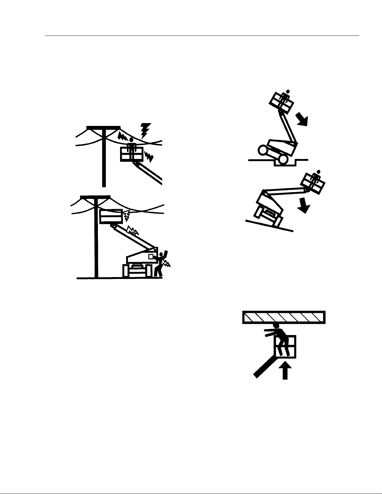
1.3 ELECTROCUTION HAZARD
MINIMUM SAFE APPROACH DISTANCE
in Meters
FROM CONTACT WITH OR PROXIMITY TO AN ELECTRICALLY CHARGED CONDUCTOR.
• MAINTAIN A CLEARANCE OF AT LEAST 3 M (10
FEET) BETWEEN ANY PART OF THE MACHINE OR
ITS LOAD AND ANY ELECTRICAL LINE OR APPARATUS CARRYING UP TO 50,000 VOLTS. 30.5 cm ADDITIONAL CLEARANCE IS REQUIRED FOR EVERY
ADDITIONAL 30,000 VOLTS OR LESS.
1.4 PRE-OPERATIONAL
• READ YOUR MANUAL. UNDERSTAND WHAT YOU’VE
READ - THEN BEGIN OPERATIONS.
• MAINTAIN SAFE CLEARANCE FROM ELECTRICAL
LINES AND APPARATUS. ALLOW FOR BOOM SWAY,
ROCK OR SAG AND ELECTRICAL LINE SWAYING.
THE MACHINE DOES NOT PROVIDE PROTECTION
• ALLOW ONLY AUTHORIZED AND QUALIFIED PERSONNEL TO OPERATE MACHINE WHO HAVE DEMONSTRATED THAT THEY UNDERSTAND SAFE AND
PROPER OPERATION AND MAINTENANCE OF THE
UNIT.
1-2 – JLG Lift – 3120890
SECTION 1 - SAFETY PRECAUTIONS
• AN OPERATOR MUST NOT ACCEPT OPERATING
RESPONSIBILITIES UNTIL ADEQUATE TRAINING HAS
BEEN GIVEN BY COMPETENT AND AUTHORIZED
PERSONS.
• BEFORE OPERATION, CHECK WORK AREA FOR
OVERHEAD ELECTRIC LINES, MACHINE TRAFFIC
SUCH AS BRIDGE CRANES, HIGHWAY, RAILWAY AND
CONSTRUCTION EQUIPMENT.
• NEVER DISABLE OR MODIFY THE FOOTSWITCH OR
ANY OTHER SAFETY DEVICE. UNAUTHORIZED MODIFICATION OF THE MACHINE IS A SAFETY VIOLATION.
• PRECAUTIONS TO AVOID ALL KNOWN HAZARDS IN
THE WORK AREA MUST BE TAKEN BY THE OPERATOR AND HIS SUPERVISOR BEFORE STARTING THE
WORK.
• DO NOT OPERATE THIS MACHINE UNLESS IT HAS
BEEN SERVICED AND MAINTAINED ACCORDING TO
THE MANUFACTURERS SPECIFICATIONS AND
SCHEDULE.
• ENSURE DAILY INSPECTION AND FUNCTION CHECK
IS PERFORMED PRIOR TO PLACING MACHINE INTO
OPERATION.
• DO NOT OPERATE MACHINE WHEN WIND CONDITIONS EXCEED 12.5 M/S (30MPH).
• NEVER OPERATE BOOM FUNCTIONS (TELE, SWING,
LIFT) WHEN MACHINE IS ON A TRUCK, OTHER VEHICLE, OR ABOVE GROUND STRUCTURE.
• THIS MACHINE CAN BE OPERATED IN NOMINAL
AMBIENT TEMPERATURES OF -20° C TO 40° C (0° F
TO 104°F). CONSULT FACTORY TO OPTIMIZE
OPERATION OUTSIDE THIS RANGE.
• APPROVED HEAD GEAR MUST BE WORN BY ALL
OPERATING AND GROUND PERSONNEL.
3120890 – JLG Lift – 1-3
SECTION 1 - SAFETY PRECAUTIONS
.
• READ AND OBEY ALL DANGERS, WARNINGS, CAUTIONS AND OPERATING INSTRUCTIONS ON
MACHINE AND IN THIS MANUAL.
• BE FAMILIAR WITH LOCATION AND OPERATION OF
GROUND STATION CONTROLS.
• ALWAYS POSITION BOOM OVER REAR (DRIVE) AXLE
IN LINE WITH DIRECTION OF TRAVEL. REMEMBER,
IF BOOM IS OVER FRONT (STEER) AXLE, DIRECTION
OF STEER AND DRIVE MOVEMENT WILL BE OPPOSITE FROM NORMAL OPERATION.
• ALWAYS USE THREE POINT CONTACT WHEN
ENTERING OR EXITING THE MACHINE. FACE THE
MACHINE WHEN YOU ENTER OR LEAVE. THREE
POINT CONTACT MEANS THAT TWO HANDS AND
ONE FOOT OR ONE HAND AND TWO FEET ARE IN
CONTACT WITH THE MACHINE AT ALL TIMES DURING MOUNT AND DISMOUNT.
1.5 DRIVING
• WATCH FOR OBSTRUCTIONS AROUND MACHINE
AND OVERHEAD WHEN DRIVING.
• DO NOT USE DRIVE FUNCTION TO POSITION PLATFORM CLOSE TO OBSTACLES. USE BOOM FUNCTION INSTEAD.
• WHEN DRIVING IN HIGH SPEED, SWITCH TO LOW
SPEED BEFORE STOPPING. TRAVEL GRADES IN
LOW DRIVE, HIGH ENGINE ONLY.
• DO NOT USE HIGH SPEED DRIVE WHEN IN
RESTRICTED OR CLOSE QUARTERS, OR WHEN
DRIVING IN REVERSE.
• BE AWARE OF STOPPING DISTANCES WHEN TRAVELING IN HIGH AND LOW SPEEDS.
• ALWAYS POST A LOOKOUT AND SOUND HORN
WHEN DRIVING IN AREAS WHERE VISION IS
OBSTRUCTED.
• KEEP NON-OPERATING PERSONNEL AT LEAST 2 M
(6 FEET) AWAY FROM MACHINE DURING DRIVING
OPERATIONS.
1-4 – JLG Lift – 3120890

SECTION 1 - SAFETY PRECAUTIONS
1.6 OPERATION.
• READ YOUR MANUAL. UNDERSTAND WHAT YOU’VE
READ - THEN BEGIN OPERATIONS.
• CHECK TRAVEL PATH FOR PERSONS, HOLES,
BUMPS, DROP-OFFS, OBSTRUCTIONS, DEBRIS,
AND COVERINGS WHICH MAY CONCEAL HOLES
AND OTHER HAZARDS.
• TRAVEL IS PERMITTED ON GRADES AND SIDESLOPES NO GREATER THAN THOSE INDICATED IN
WARNING PLACARD AT MACHINE PLATFORM.
• OPERATION WITH BOOM RAISED IS RESTRICTED
TO FIRM, LEVEL AND UNIFORM SURFACE.
• DO NOT TRAVEL ON SOFT OR UNEVEN SURFACES,
AS TIPPING WILL OCCUR.
• DO NOT DRIVE MACHINE NEAR PITS, LOADING
DOCKS OR OTHER DROP-OFFS.
• PRIOR TO ENTERING AND EXITING PLATFORM AT
GROUND LEVEL, FULLY LOWER THE BOOM.
EXTEND BOOM UNTIL END OF FLY BOOM CONTACTS GROUND. WITH BOOM LIFT IN THIS CONFIGURATION, ENTER AND/OR EXIT PLATFORM
THROUGH GATE OPENING.
• JLG RECOMMENDS ALL PERSONS IN THE PLATFORM TO WEAR LANYARDS WITH AN APPROVED
FALL PROTECTION DEVICE. SECURE LANYARD TO
DESIGNATED LANYARD ATTACH POINT ON PLATFORM. KEEP GATE CLOSED AT ALL TIMES.
• TO AVOID FALLING - USE EXTREME CAUTION WHEN
ENTERING OR LEAVING PLATFORM ABOVE
GROUND. ENTER OR EXIT THRU GATE ONLY. PLATFORM FLOOR MUST BE WITHIN 30CM (1 FOOT) OF
ADJACENT - SAFE AND SECURE - STRUCTURE.
ALLOW FOR PLATFORM VERTICAL MOVEMENT AS
WEIGHT IS TRANSFERRED TO OR FROM PLATFORM.
3120890 – JLG Lift – 1-5

SECTION 1 - SAFETY PRECAUTIONS
• TRANSFERS BETWEEN A STRUCTURE AND THE
AERIAL PLATFORM EXPOSE OPERATORS TO FALL
HAZARDS. THIS PRACTICE SHOULD BE DISCOURAGED WHEREVER POSSIBLE. WHERE TRANSFER
MUST BE ACCOMPLISHED TO PERFORM THE JOB
TWO LANYARDS WITH AN APPROVED FALL PROTECTION DEVICE WILL BE USED. ONE LANYARD
SHOULD BE ATTACHED TO THE AERIAL PLATFORM.
THE OTHER TO THE STRUCTURE. THE LANYARD
THAT IS ATTACHED TO THE AERIAL PLATFORM
SHOULD NOT BE DISCONNECTED UNTIL SUCH
TIME AS THE TRANSFER TO THE STRUCTURE IS
COMPLETE. OTHERWISE, DO NOT STEP OUTSIDE
OF PLATFORM.
• DO NOT ADD NOTICE BOARDS OR SIMILAR ITEMS
TO THE PLATFORM. ADDITION OF SUCH ITEMS
INCREASES THE EXPOSED WIND AREA OF THE
MACHINE.
• NEVER POSITION LADDERS, STEPS, OR SIMILAR
ITEMS ON UNIT TO PROVIDE ADDITIONAL REACH
FOR ANY PURPOSE.
• WHEN RIDING IN OR WORKING FROM PLATFORM,
BOTH FEET MUST BE FIRMLY POSITIONED ON THE
FLOOR.
• KEEP OIL, MUD AND SLIPPERY SUBSTANCES
CLEANED FROM FOOTWEAR AND PLATFORM
FLOOR.
• NEVER "WALK" THE BOOM TO GAIN ACCESS TO OR
LEAVE PLATFORM.
• NEVER PLACE HANDS OR ARMS IN TOWER BOOM
OR UPRIGHT MECHANISM.
• KEEP ALL NON-OPERATING PERSONNEL AT LEAST
2 METERS AWAY FROM THE MACHINE AT ALL
TIMES.
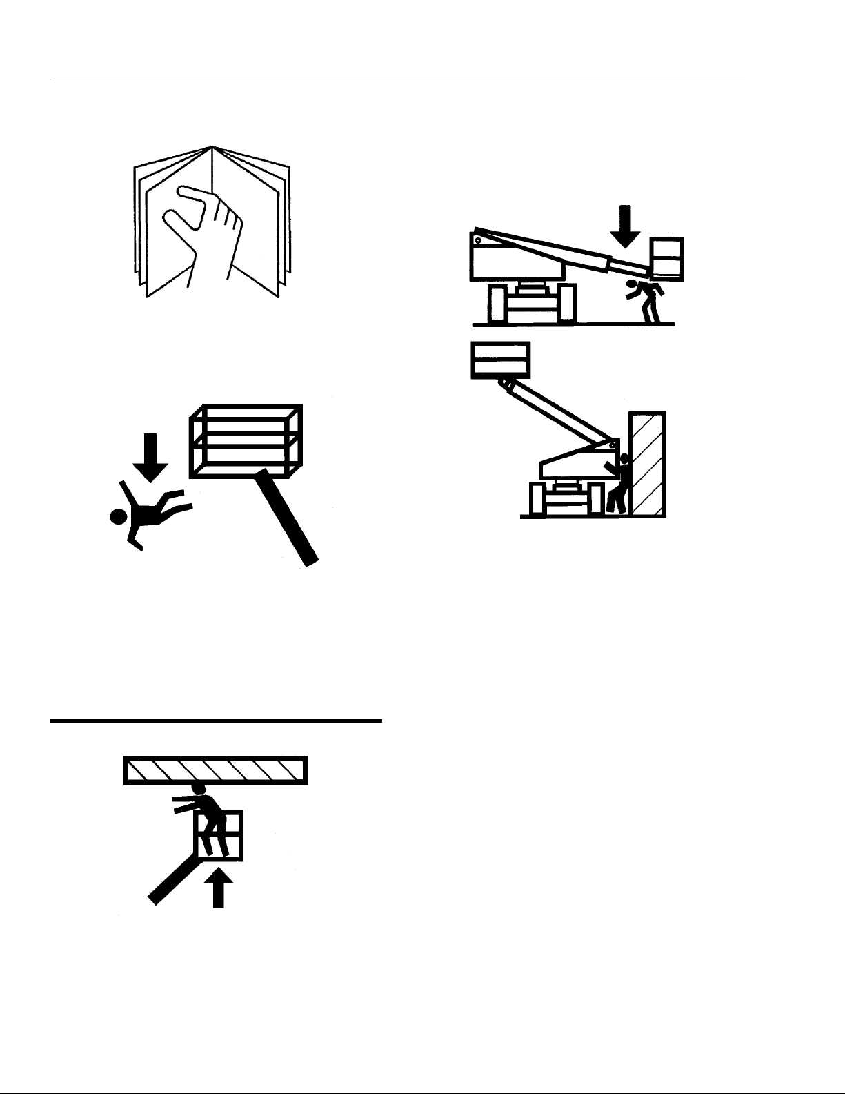
• IF PLATFORM OR BOOM IS CAUGHT SO THAT ONE
OR MORE WHEELS ARE OFF THE FLOOR, ALL PERSONNEL MUST BE REMOVED FROM PLATFORM
BEFORE ATTEMPTING TO FREE MACHINE. USE
CRANES, FORKLIFT TRUCKS OR OTHER EQUIPMENT TO REMOVE PERSONNEL AND STABILIZE
MACHINE MOTION, IF NECESSARY.
• THE OPERATOR IS RESPONSIBLE TO AVOID OPERATING MACHINE OVER GROUND PERSONNEL AND
TO WARN THEM NOT TO WORK, WALK OR STAND
UNDER A RAISED BOOM OR PLATFORM. POSITION
BARRICADES ON FLOOR IF NECESSARY.
1-6 – JLG Lift – 3120890

SECTION 1 - SAFETY PRECAUTIONS
.
• ENSURE MACHINE IS POSITIONED ON A FIRM,
LEVEL AND UNIFORM SUPPORTING SURFACE
BEFORE RAISING OR EXTENDING BOOM.
• CHECK CLEARANCES ABOVE, ON SIDES AND BOTTOM OF PLATFORM WHEN RAISING, LOWERING,
SWINGING, AND TELESCOPING BOOM.
• EXERCISE EXTREME CAUTION AT ALL TIMES TO
PREVENT OBSTACLES FROM STRIKING OR INTER-
FERING WITH OPERATING CONTROLS AND PERSONS IN PLATFORM.
• ENSURE THAT OPERATORS OF OTHER OVERHEAD
AND FLOOR MACHINES ARE AWARE OF THE AERIAL
PLATFORMS PRESENCE. DISCONNECT POWER TO
OVERHEAD CRANES. POSITION BARRICADES ON
FLOOR IF NECESSARY.
• NEVER "SLAM" A CONTROL SWITCH OR LEVER
THROUGH NEUTRAL TO THE OPPOSITE DIRECTION.
ALWAYS RETURN SWITCH TO NEUTRAL AND STOP;
THEN MOVE SWITCH TO THE DESIRED POSITION.
OPERATE LEVERS WITH SLOW, EVEN PRESSURE.
• DO NOT CARRY MATERIALS ON PLATFORM RAILING
UNLESS APPROVED BY JLG INDUSTRIES INC.
• NEVER PUSH OR PULL THE MACHINE OR OTHER
OBJECTS BY TELESCOPING THE BOOM.
• NEVER USE BOOM FOR ANY PURPOSE OTHER
THAN POSITIONING PERSONNEL, THEIR TOOLS
AND EQUIPMENT.
• NEVER EXCEED MANUFACTURERS RATED PLATFORM CAPACITY - REFER TO CAPACITY DECAL ON
MACHINE. DISTRIBUTE LOADS EVENLY ON PLATFORM FLOOR.
• NEVER OPERATE A MALFUNCTIONING MACHINE. IF
A MALFUNCTION OCCURS, SHUT DOWN THE
MACHINE, RED TAG IT, AND NOTIFY PROPER
AUTHORITIES.
• DO NOT REMOVE, MODIFY, OR DISABLE FOOTSWITCH BY BLOCKING OR ANY OTHER MEANS.
• DO NOT ASSIST A STUCK OR DISABLED MACHINE
BY PUSHING OR PULLING EXCEPT BY PULLING AT
CHASSIS TIE-DOWN LUGS.
• NEVER ATTEMPT USING BOOM AS A CRANE.
STRUCTURAL DAMAGE OR TIPPING MAY OCCUR.
• STOW BOOM AND SHUT OFF ALL POWER BEFORE
LEAVING MACHINE.
• NO STUNT DRIVING OR HORSEPLAY IS PERMITTED.
3120890 – JLG Lift – 1-7

SECTION 1 - SAFETY PRECAUTIONS
• NEVER ATTEMPT TO FREE A MACHINE STUCK IN
SOFT GROUND OR ASSIST A MACHINE UP A STEEP
HILL OR RAMP BY USING BOOM "LIFT", "TELESCOPE", OR "SWING" FUNCTIONS.
• NEVER ATTACH WIRE, CABLE, OR ANY SIMILAR
ITEMS TO PLATFORM.
• DO NOT PLACE BOOM OR PLATFORM AGAINST ANY
STRUCTURE TO STEADY PLATFORM OR SUPPORT
STRUCTURES.
• DO NOT USE THE LIFT, SWING, OR TELESCOPE
FUNCTIONS FOR THE BOOM, TO MOVE EITHER THE
MACHINE OR OTHER OBJECTS.
• HYDRAULIC CYLINDERS SHOULD NEVER BE LEFT
FULLY EXTENDED OR RETRACTED FOR ANY
LENGTH OF TIME. ALWAYS "BUMP" CONTROL IN
OPPOSITE DIRECTION SLIGHTLY WHEN FUNCTION
BEING USED REACHES END OF TRAVEL. THIS
APPLIES TO MACHINES IN OPERATION OR IN
STOWED MODE.
• DO NOT OPERATE ANY MACHINE ON WHICH DANGER, WARNING, CAUTION OR INSTRUCTION PLACARDS OR DECALS ARE MISSING OR ILLEGIBLE.
• MACHINE MUST ALWAYS BE SHUT DOWN WHEN
REFUELING. NO SMOKING IS MANDATORY. NEVER
REFUEL DURING AN ELECTRICAL STORM. ENSURE
THAT FUEL CAP IS CLOSED AND SECURE AT ALL
OTHER TIMES.
1.7 TOWING AND HAULING
• DO NOT TOW A MACHINE EXCEPT IN AN EMERGENCY. SEE SECTION 6 FOR EMERGENCY TOWING
PROCEDURES.
• LOCK TURNTABLE BEFORE TRAVELING LONG DISTANCES OR BEFORE HAULING MACHINE ON A
TRUCK OR TRAILER.
1-8 – JLG Lift – 3120890

SECTION 2 - PREPARATION AND INSPECTION
SECTION 2. PREPARATION AND INSPECTION
2.1 GENERAL
This section provides the necessary information needed
by those personnel that are responsible to place the
machine in operation readiness, and lists checks that are
performed prior to use of the machine. It is important that
the information contained in this section be read and
understood before any attempt is made to operate the
machine. Ensure that all the necessary inspections have
been completed successfully before placing the machine
into service. These procedures will aid in obtaining maximum service life and safe operation.
SINCE THE MACHINE MANUFACTURER HAS NO DIRECT CONTROL OVER THE FIELD INSPECTION AND MAINTENANCE,
SAFETY IS THE RESPONSIBILITY OF THE OWNER/OPERATOR.
2.2 PREPARATION FOR USE
Before a new machine is put into operation it must be
carefully inspected for any evidence of damage resulting
from shipment and inspected periodically thereafter, as
outlined in Delivery and Frequent Inspection (see section
2-3). During initial start-up and run, the unit should be
thoroughly checked for hydraulic leaks. A check of all
components should be made to ensure their security.
All preparation necessary to place the machine in operation readiness status is the responsibility of management
personnel. Preparation requires good common sense,
(i.e. telescope works smoothly and brakes operate properly) coupled with a series of visual inspections. The mandatory requirements are given in the Daily Walk Around
Inspection (see section 2-4).
It should be assured that the items appearing in the Delivery and Frequent Inspection and Functional Check are
complied with prior to putting the machine into service.
2.3 DELIVERY AND FREQUENT INSPECTION
NOTE: This machine requires periodic safety and mainte-
nance inspections by an authorized JLG Dealer.
The following checklist provides a systematic inspection
to assist in detecting defective, damaged, or improperly
installed parts. The checklist denotes the items to be
inspected and conditions to examine.
Frequent inspection shall be performed every 3 months or
150 hours whichever comes first, or more often when
required by environment, severity, and frequency of
usage.
Chassis
1. Check front tire and wheel assemblies for loose or
worn spindles, components and hardware for security, tires for wear and damage.
2. Check steering assembly for loose or bent tie rod,
cylinder and hydraulic lines for leaks and security,
and hardware for proper installation.
3. Check rear tire and wheel assemblies for security,
tires for wear and damage.
4. Check drive hubs, hydraulic motors, brakes and
hydraulic lines for damage and leaks.
5. Check oil level in drive hub by removing pipe plug
on side and feeling for oil level. (Contact Service
Personnel for assistance if needed).
NOTE: Torque hubs should be one-half full of lubricant.
6. Check 4WS steering assembly (if equipped) for
loose or bent tie rod, cylinder and hydraulic lines for
leaks and security, and hardware for proper installation.
7. Check counterbalance, flow divider valves, hydraulic
swivel assembly and lines for visible damage, evidence of leakage, and security and electrical connections for corrosion and tightness.
8. Check extending axle assemblies for evidence of
leakage and security; pressure lines for abnormal
chafing drive hubs, hydraulic motors, brakes and
hydraulic lines for damage and leaks.
3120890 – JLG Lift – 2-1

SECTION 2 - PREPARATION AND INSPECTION
9. Check extending axles for visible damage and loose
or missing parts.
10. Check oscillating axle (if equipped) for loose, missing and worn parts, pivot pin and lockout cylinder
pins for security, lockout cylinders and hydraulic
hoses for damage and leaks.
Turn tab le
1. Check turntable and turntable lock for damage,
loose or missing parts, and security. Check swing
drive hub, hydraulic motor, and brake for damage,
loose or missing parts, hydraulic lines and component housings for evidence of leakage; pinion for
proper mesh with swing gear.
10. Check fuel tank for damage, leakage and filler cap
for security.
11. Check hydraulic reservoir and hydraulic lines for
damage, leakage and security.
NOTE: JLG recommends replacing the hydraulic filter ele-
ment after the first 50 hours of operation and then
every 300 hours thereafter, unless system indicator
require earlier replacement.
12. Check all cylinder pin and shaft retaining hardware
for security and wear.
13. Check all electrical cables for defects, damage,
loose or corroded connections.
Boom
2. Check swing bearing for damage, wear, lubrication
and loose or missing bearing bolts.
3. Check solenoid valves and hydraulic lines for damage, leakage, security and electrical connections for
tightness and evidence of corrosion.
4. Check ground controls for damage, loose or missing parts, security, electrical connections for evidence of corrosion and tightness and wiring for
insulation damage. Assure that all switches function
properly.
5. Check manual descent valves for visible damage,
evidence of leakage and security. Assure that valves
function properly.
6. Check battery for damage, loose or missing vent
caps, electrical connections for tightness, and evidence of corrosion, holddown brackets for tightness, and electrolyte for proper water level. Add only
clean distilled water to battery.
7. Check engine and accessories for damage, loose or
missing parts, leakage and security. Check throttle
solenoid and linkage for damage, electrical connections for tightness, and evidence of corrosion and
wiring for insulation damage.
8. Check fuel lines for damage, leakage and security.
9. Check all access doors for damage, proper operation of latches, props and security.
1. Check all cylinder pin and shaft retaining hardware
for security and wear.
2. Check hydraulic lines, electrical cable and track
assemblies for damage, missing parts and security.
3. Check lift cylinder and cross pins and hydraulic
lines for damage, wear, leakage and security.
4. Check boom pivot pins for damage, wear, and security.
5. Check hydraulic line and electrical cable track
assembly for visible damage, loose or missing parts,
and security.
6. Check boom for damage, missing parts and security.
7. Check boom wear pads for damage, wear and security.
8. Check boom telescope cylinder and cross pins and
hydraulic lines for damage, wear, leakage and security.
9. Check platform leveling cylinder and cross pins and
hydraulic lines for damage, wear, leakage and security.
10. Check boom/platform pivot pin for damage, wear
and security.
2-2 – JLG Lift – 3120890

SECTION 2 - PREPARATION AND INSPECTION
Figure 2-1. Machine Nomenclature
3120890 – JLG Lift – 2-3

SECTION 2 - PREPARATION AND INSPECTION
11. Check horizontal and capacity limit switches
mounted on turntable for security of mounting, damage to switch arms and rollers; and for debris.
12. Check boom tape for correct length and tearing or
defacing at any point.
Extend-A-Reach (If Equipped)
1. Check the slave cylinder, weld link and cross pins,
and lines for visible damage, wear, lubrication, evidence of leakage, and security.
2. Check extend-a-reach for visible damage, loose or
missing parts, and security.
3. Check hydraulic lines and electrical cable for damage, missing parts and security.
Platform
1. Check platform and control console for damage,
loose or missing parts, and security.
2. Check control switches and levers for damage,
loose or missing parts and security. Assure that
levers function properly.
3. Check control switches, levers and electrical connections for tightness and evidence of corrosion,
and wiring for defects and chafing damage. Assure
that switches function properly.
4. Check capacity indicator for correct operation, any
damage and that decals are not defaced. Ensure
indicator dial is zeroed with boom at horizontal and
indicator dial moves in accordance with boom
angle.
5. Check access gate hinges and latch for proper
operation, damage and security.
6. Check platform rotator mechanism for proper operation, damage, security. Check hydraulic lines for
leakage, damage and security.
Torque Requirements
The Torque Chart (Figure 2-6.) consists of standard torque
values based on bolt diameter and grade, also specifying
dry and wet torque values in accordance with recommended shop practices. This chart is provided as an aid
to the operator in the event he/she notices a condition that
requires prompt attention during the walk-around inspection or during operation, until the proper service personnel
can be notified. The Service and Maintenance manual
provides specific torque values and periodic maintenance
procedures with a listing of individual components. Utilizing this Torque Chart in conjunction with the preventive
maintenance section in the Service and Maintenance
manual will enhance safety, reliability, and performance of
the machine.
2.4 DAILY WALK-AROUND INSPECTION
It is the operator’s responsibility to inspect the machine
before the start of each workday. It is recommended that
each operator inspect the machine before operation, even
if the machine has already been put into service under
another operator. This Daily Walk-Around Inspection is the
preferred method of inspection.
(See Figure 2-2.)
In addition to the Daily Walk-Around Inspection, be sure to
include the following as part of the daily inspection:
1. Overall cleanliness.
Check all standing surfaces for oil, fuel and hydraulic oil spillage and foreign objects. Ensure overall
cleanliness.
2. Placards.
Keep all information and operating placards clean
and unobstructed. Cover when spray painting or
shot blasting to protect legibility.
3. Operator’s and Safety Manual.
Ensure a copy of this manual is enclosed in the
manual storage box.
NOTE: Check all DANGER, WARNING, CAUTION and
INSTRUCTION placards for legibility and security on
the entire machine.
2-4 – JLG Lift – 3120890

SECTION 2 - PREPARATION AND INSPECTION
4. 4. Machine Log.
Ensure a machine operating record or log is kept,
check to see that it is current and that no entries
have been left uncleared, leaving machine in an
unsafe condition for operation.
5. Start each day with a full fuel tank.
TO AVOID INJURY, DO NOT OPERATE A MACHINE UNTIL ALL
MALFUNCTIONS HAVE BEEN CORRECTED. USE OF A MALFUNCTIONING MACHINE IS A SAFETY VIOLATION.
TO AVOID POSSIBLE INJURY, BE SURE MACHINE POWER IS
“OFF” DURING WALK-AROUND INSPECTION.
NOTE: Check boom horizontal limit switch for proper opera-
tion and security, both visually and manually. Switch
must shut down high engine and high drive speed
when boom is raised above horizontal:
6. Check platform footswitch for proper operation.
Switch must be released to start engine and
depressed to operate machine.
7. Check that drive brakes hold when machine is
driven up a grade and stopped.
NOTE: On new machines, those recently overhauled, or
after changing hydraulic oil, operate all systems a
minimum of two complete cycles and recheck oil
level in reservoir.
8. Assure that all items requiring lubrication are serviced. Refer to Table 2-1, Lubrication Chart, for specific requirements.
3120890 – JLG Lift – 2-5

SECTION 2 - PREPARATION AND INSPECTION
Figure 2-2. Daily Walk-Around Inspection - Sheet 1 of 4
2-6 – JLG Lift – 3120890

SECTION 2 - PREPARATION AND INSPECTION
GENERAL
NOTE: Begin the “Walk-Around Inspection” at Item 1, as
noted on the diagram. Continue to the right (counterclockwise viewed from top) checking each item in
sequence for the conditions listed in the “WalkAround Inspection Checklist”.
TO AVOID INJURY, DO NOT OPERATE A MACHINE UNTIL ALL
MALFUNCTIONS HAVE BEEN CORRECTED. USE OF A MALFUNCTIONING MACHINE IS A SAFETY VIOLATION. TO AVOID POSSIBLE INJURY, BE SURE MACHINE POWER IS “OFF” DURING
WALK-AROUND INSPECTION.
NOTE: Do not overlook visual inspection of chassis under-
side. Checking this area often results in discovery of
conditions which could cause extensive machine
damage.
1. Platform Assembly - No loose or missing parts, no
visible damage. Lock bolts in place. Footswitch in
good working order, not modified, disabled or
blocked. Check area of fly boom nose section
above and under platform slave level cylinder for
accumulation of foreign material. Remove any foreign material present.
2. Platform Control Console - Switches and levers
return to neutral and are properly secured, no loose
or missing parts, no visible damage, decals/placards secure and legible, control marking legible.
3. Rotator - Properly secured, no visible damage, no
evidence of leakage.
4. Rotator and Motor - Properly secured, no visible
damage, no evidence of leakage.
5. Slave Leveling Cylinder, Extend-A-Reach - Prop-
erly secured, no visible damage, no evidence of
leakage. (If equipped on Extend-A-Reach)
6. Extend-A-Reach Lift Cylinder - Properly secured,
no visible damage, or signs of leakage, evidence of
proper lubrication. (If equipped on Extend-A-Reach)
7. Extend-A-Reach Pivot - No loose, damaged, or
missing parts, evidence of proper lubrication. (If
equipped on Extend-A-Reach)
8. Hose and Cable Guards/Clamps - Properly
secured, no visible damage.
9. Power Track - No loose, damaged or missing parts,
no visible damage.
10. Steer Cylinder Assembly, Right Rear - Properly
secured, no visible damage or signs of leakage. (4
Wheel Steer)
11. Tie Rod and Steering Linkage - No loose or miss-
ing parts, no visible damage. Tie rod end studs
locked. (4 Wheel Steer)
12. Drive Motor and Brake, Right Rear - No visible
damage, no evidence of leakage.
13. Spindle, Right Rear - No loose or missing parts, no
visible damage, evidence of proper lubrication. (4
Wheel Steer)
14. Drive Hub, Right Rear - No visible damage, no evi-
dence of leakage.
15. Wheel/Tire Assembly, Right Rear - Properly
secured, no loose or missing lug nuts, no visible
damage.
16. Turntable Bearing and Pinion - No loose or miss-
ing hardware; no visible damage, evidence of
proper lubrication. No evidence of loose bolts or
looseness between bearing and structure.
17. Swing Drive Motor and Brake - No visible damage,
no evidence of leakage.
18. Fuel Supply - Fuel filler cap secure. Tank - no visible
damage; no evidence of leaks.
19. Extend-A-Reach Control valves (Tank Compart-
ment) No visible damage, no evidence of leakage,
no unsupported wires or hoses, no damaged wires.
Figure 2-3. Daily Walk-Around Inspection - Sheet 2 of 4
3120890 – JLG Lift – 2-7

SECTION 2 - PREPARATION AND INSPECTION
20. Control Valves (Tank Compartment) - No loose or
missing parts, no evidence of leakage, no damaged
wires.
21. Hydraulic Oil Supply - Recommended oil level in
sight gauge. (Check level with cold oil, systems shut
down, machine in stowed position) Cap in place
and secure.
22. Steer Cylinder Assembly - Properly secured, no
visible damage or signs of leakage.
23. Cowling and Latches, Right Side - All cowling and
latches in working condition, properly secured, no
loose or missing part.
24. Spindle, Right Front - Properly secured, no loose
or missing parts, no visible damage.
25. Drive Hub, Right Front - No visible damage, no evidence of leakage. (4 Wheel Drive)
26. Wheel/Tire Assembly, Right Front - Properly
secured, no loose or missing lug nuts, no visible
damage.
27. Tie Rod and Steering Linkage, Right Front - No
loose or missing parts, no visible damage. Tie rod
end studs locked.
28. Axle Lock Pin, Right Front - No loose or missing
parts, no visible damage. Installed in proper location.
29. Oscillating Axle Cylinder, Right Front - Properly
secured, no visible damage or signs of leakage. (If
Equipped)
30. Ground Controls - Switches operable, no visible
damage, decals secure and legible.
31. Manual Descent - No evidence of leakage, no visible damage.
32. Oscillating Axle - Properly secured, no loose or
missing parts, no visible damage. (If Equipped)
33. To wi n g P a c ka ge - No loose, damaged or missing
parts, no visible damage. (If Equipped)
34. Master Cylinder - Properly secured, evidence of
lubrication.
35. Lift Cylinder - Properly secured, evidence of lubri-
cation.
36. Oscillating Axle Cylinder, Left Front - Properly
secured, no visible damage or signs of leakage. (If
Equipped)
37. Axle Lock Pin, Left Front - No loose or missing
parts, no visible damage. Installed in proper location.
38. Tie Rod and Steering Linkage, Left Front - No
loose or missing parts, no visible damage. Tie rod
end studs locked.
39. Auxiliary Power Pump - No loose or missing parts,
no evidence of leakage, no damaged wires.
40. Wheel/Tire Assembly, Left Front - Properly
secured, no loose or missing lug nuts, no visible
damage.
Spindle, Left Front - Properly secured, no loose or
41.
missing parts, no visible damage.
42. Drive Hub, Right Front - No visible damage, no evidence of leakage. (4 Wheel Drive)
43. Hydraulic Pump - No loose or missing parts, no evidence of leakage.
44. Muffler and Exhaust System - Properly secured,
no evidence of leakage
45. Engine Oil Supply - Full mark on dipstick; filler cap
secure.
46. Cowling and Latches, Left Side - All cowling and
latches in working condition, properly secured, no
loose or missing part.
47. Engine Air Filter - No loose or missing parts; no visible damage; element clean.
48. Battery - Proper electrolyte levels; cables tight, no
visible damage or corrosion.
49. Tur n t a b l e L oc k - Operable; No missing parts, no
visible damage.
50. Wheel/Tire Assembly, Left Rear - Properly
secured, no loose or missing lug nuts, no visible
damage.
Figure 2-4. Daily Walk-Around Inspection - Sheet 3 of 4
2-8 – JLG Lift – 3120890
 Loading...