

Page 1
Operation and Safety Manual
®
Original Instructions - Keep this manual with the machine at all times.
Model(s)
15/20MVL
15/20MSP
ANSI
P/N - 3121230
December 20, 2013
Page 2

NOTES:
Page 3

SECTION - FOREWORD
FOREWORD
This manual is a very important tool! Keep it with the machine at all times.
The purpose of this manual is to provide owners, users, operators, lessors, and lessees with the precautions and
operating procedures essential for the safe and proper machine operation for its intended purpose.
Due to continuous product improvements, JLG Industries, Inc. reserves the right to make specification changes
without prior notification. Contact JLG Industries, Inc. for updated information.
Other Publications Available:
Service Manual . . . . . . . . . . . . . . . . . . . . . . . . . . 3121231
Illustrated Parts Manual. . . . . . . . . . . . . . . . . . . . 3121232
3121230 – JLG Lift – a
Page 4
SECTION - SAFETY ALERT SYMBOLS AND SAFETY SIGNAL WORDS
SAFETY ALERT SYMBOLS AND SAFETY SIGNAL WORDS
This is the Safety Alert Symbol. It is used to alert you to the potential personal
injury hazards. Obey all safety messages that follow this symbol to avoid possible
injury or death
INDICATES AN IMMINENTLY HAZARDOUS SITUATION. IF NOT
AVOIDED, WILL RESULT IN SERIOUS INJURY OR DEATH. THIS DECAL
WILL HAVE A RED BACKGROUND.
INDICATES A POTENTIALITY HAZARDOUS SITUATION. IF NOT
AVOIDED, COULD
DECAL WILL HAVE AN ORANGE BACKGROUND.
RESULT IN SERIOUS INJURY OR DEATH. THIS
INDICATES A POTENTIALITY HAZARDOUS SITUATION. IF NOT
AVOIDED, MAY RESULT IN MINOR OR MODERATE INJURY. IT MAY
ALSO ALERT AGAINST UNSAFE PRACTICES. THIS DECAL WILL HAVE
A YELLOW BACKGROUND.
INDICATES INFORMATION OR A COMPANY POLICY THAT RELATES
DIRECTLY OR INDIRECTLY TO THE SAFETY OF PERSONNEL OR PROTECTION OF PROPERTY.
b – JLG Lift – 3121230
Page 5

SECTION - SAFETY ALERT SYMBOLS AND SAFETY SIGNAL WORDS
THIS PRODUCT MUST COMPLY WITH ALL SAFETY RELATED BULLETINS. CONTACT JLG INDUSTRIES, INC. OR THE LOCAL AUTHORIZED
JLG REPRESENTATIVE FOR INFORMATION REGARDING SAFETY
RELATED BULLETINS WHICH MAY HAVE BEEN ISSUED FOR THIS
PRODUCT.
For :
• Accident Reporting
• Product Safety Publications
• Current Owner Updates
• Questions Regarding
Product Safety
• Standards and Regulations
Compliance Information
• Questions Regarding Special Product Applications
• Questions Regarding Product Modifications
JLG INDUSTRIES, INC. SENDS SAFETY RELATED BULLETINS TO THE
OWNER OF RECORD OF THIS MACHINE. CONTACT JLG INDUSTRIES,
INC. TO ENSURE THAT THE CURRENT OWNER RECORDS ARE
UPDATED AND ACCURATE.
JLG INDUSTRIES, INC. MUST BE NOTIFIED IMMEDIATELY IN ALL
INSTANCES WHERE JLG PRODUCTS HAVE BEEN INVOLVED IN AN
ACCIDENT INVOLVING BODILY INJURY OR DEATH OF PERSONNEL OR
WHEN SUBSTANTIAL DAMAGE HAS OCCURRED TO PERSONAL
PROPERTY OR THE JLG PRODUCT.
Contact :
Product Safety and Reliability Department
JLG Industries, Inc.
13224 Fountainhead Plaza
Hagerstown, MD 21742
or Your Local JLG Office
(See addresses on inside of manual cover)
In USA:
Toll Free: 877-JLG-SAFE (877-554-7233)
Outside USA:
3121230 – JLG Lift – c
Phone: 240-420-2661
E-mail: ProductSafety@JLG.com
Page 6

SECTION - REVISION LOG
REVISION LOG
Original Issue of Manual . . . . . . . . . . . . . . November 29, 2005
Manual Revised. . . . . . . . . . . . . . . . . . . . . . . . . . April 19, 2006
Manual Revised. . . . . . . . . . . . . . . . . . . . . . . . October 4, 2006
Manual Revised. . . . . . . . . . . . . . . . . . . . . . . . . . . April 2, 2007
Manual Revised. . . . . . . . . . . . . . . . . . . . . . November 6, 2007
Manual Revised. . . . . . . . . . . . . . . . . . . . . . . . . . May 12, 2009
Manual Revised. . . . . . . . . . . . . . . . . . . . . December 22, 2009
Manual Revised. . . . . . . . . . . . . . . . . . . . . November 24, 2010
Manual Revised. . . . . . . . . . . . . . . . . . . . . . .February 24, 2012
Manual Revised. . . . . . . . . . . . . . . . . . . . . . December 5, 2013
Manual Revised. . . . . . . . . . . . . . . . . . . . . December 20, 2013
d – JLG Lift – 3121230
Page 7

TABLE OF CONTENTS
SECTION - PARAGRAPH, SUBJECT PAGE SECTION - PARAGRAPH, SUBJECT PAGE
FOREWORD . . . . . . . . . . . . . . . . . . . . . . . . . . . . . . . . . . A
SAFETY ALERT SYMBOLS AND SAFETY SIGNAL
WORDS. . . . . . . . . . . . . . . . . . . . . . . . . . . . . . . . . . . . . . B
Contact : . . . . . . . . . . . . . . . . . . . . . . . . . . . . . . . . . . . C
In USA:. . . . . . . . . . . . . . . . . . . . . . . . . . . . . . . . . . . . . C
Outside USA: . . . . . . . . . . . . . . . . . . . . . . . . . . . . . . . . C
REVISION LOG. . . . . . . . . . . . . . . . . . . . . . . . . . . . . . . . D
SECTION - 1 - SAFETY PRECAUTIONS
1.1 GENERAL . . . . . . . . . . . . . . . . . . . . . . . . . . . . . . . . . . . 1-1
1.2 PRE-OPERATION . . . . . . . . . . . . . . . . . . . . . . . . . . . . . 1-1
Operator Training And Knowledge . . . . . . . . . . . . . . 1-1
Workplace Inspection . . . . . . . . . . . . . . . . . . . . . . . . 1-2
Machine Inspection . . . . . . . . . . . . . . . . . . . . . . . . . . 1-2
1.3 OPERATION . . . . . . . . . . . . . . . . . . . . . . . . . . . . . . . . . 1-3
General . . . . . . . . . . . . . . . . . . . . . . . . . . . . . . . . . . . 1-3
Trip and Fall Hazard . . . . . . . . . . . . . . . . . . . . . . . . . 1-3
Electrocution Hazards . . . . . . . . . . . . . . . . . . . . . . . . 1-4
Tipping Hazard . . . . . . . . . . . . . . . . . . . . . . . . . . . . . 1-6
Crushing And Collision Hazard . . . . . . . . . . . . . . . . . 1-7
1.4 TOWING, LIFTING, AND HAULING . . . . . . . . . . . . . . . 1-8
SECTION - 2 - PREPARATION AND INSPECTION
2.1 PERSONNEL TRAINING . . . . . . . . . . . . . . . . . . . . . . . .2-1
Operator Training . . . . . . . . . . . . . . . . . . . . . . . . . . . 2-1
Training Supervision . . . . . . . . . . . . . . . . . . . . . . . . 2-2
Operator Responsibility . . . . . . . . . . . . . . . . . . . . . . 2-2
2.2 PREPARATION, INSPECTION, AND MAINTENANCE . 2-2
2.3 PRE-START INSPECTION. . . . . . . . . . . . . . . . . . . . . . . 2-4
2.4 DAILY WALK-AROUND INSPECTION. . . . . . . . . . . . . .2-5
2.5 FUNCTION CHECK. . . . . . . . . . . . . . . . . . . . . . . . . . . . 2-7
SECTION - 3 - MACHINE CONTROLS, INDICATORS AND OPERATION
3.1 GENERAL . . . . . . . . . . . . . . . . . . . . . . . . . . . . . . . . . . .3-1
3.2 MACHINE DESCRIPTION . . . . . . . . . . . . . . . . . . . . . . .3-1
3.3 MACHINE OPERATION. . . . . . . . . . . . . . . . . . . . . . . . . 3-2
Getting Started . . . . . . . . . . . . . . . . . . . . . . . . . . . . . 3-2
3.4 BATTERY CHARGING. . . . . . . . . . . . . . . . . . . . . . . . . .3-2
Battery - Low Voltage Warning Indicators . . . . . . . . 3-3
To Charge Batteries . . . . . . . . . . . . . . . . . . . . . . . . . 3-4
Battery Charging Status Indicators . . . . . . . . . . . . . 3-4
3.5 GROUND CONTROL STATION - OPERATION. . . . . . . 3-7
Main Power Selector Switch . . . . . . . . . . . . . . . . . . 3-7
Emergency Stop/Shut Down Button . . . . . . . . . . . . 3-7
3121230 – JLG Lift – i
Page 8

TABLE OF CONTENTS
SECTION - PARAGRAPH, SUBJECT PAGE SECTION - PARAGRAPH, SUBJECT PAGE
Brake Release Button . . . . . . . . . . . . . . . . . . . . . . . . 3-7
Platform Up . . . . . . . . . . . . . . . . . . . . . . . . . . . . . . . . 3-9
Platform Down . . . . . . . . . . . . . . . . . . . . . . . . . . . . . 3-9
Manual Descent Control Valve . . . . . . . . . . . . . . . . . 3-9
Machine Status LCD Display . . . . . . . . . . . . . . . . . 3-10
LCD Display Fault Conditions. . . . . . . . . . . . . . . . . 3-11
3.6 PLATFORM CONTROL CONSOLE OPERATION . . . 3-15
General . . . . . . . . . . . . . . . . . . . . . . . . . . . . . . . . . . 3-16
Platform On/Off Key Switch . . . . . . . . . . . . . . . . . . 3-16
Platform Emergency Stop Button. . . . . . . . . . . . . . 3-17
Platform Control Display Panel. . . . . . . . . . . . . . . . 3-17
Drive/Lift Mode Selector Switch . . . . . . . . . . . . . . . 3-19
Horn Button. . . . . . . . . . . . . . . . . . . . . . . . . . . . . . . 3-19
Joystick Function Enable Lever . . . . . . . . . . . . . . . 3-19
Multifunction Joystick Control . . . . . . . . . . . . . . . . 3-20
Drive Mode . . . . . . . . . . . . . . . . . . . . . . . . . . . . . . . 3-20
Lift Mode . . . . . . . . . . . . . . . . . . . . . . . . . . . . . . . . . 3-22
Drive Speed Setting Controls . . . . . . . . . . . . . . . . . 3-23
3.7 PARKING MACHINE . . . . . . . . . . . . . . . . . . . . . . . . . 3-24
3.8 PLATFORM CONFIGURATIONS . . . . . . . . . . . . . . . . 3-24
StockPicking Platform Operation . . . . . . . . . . . . . . 3-28
3.9 FALL PROTECTION - LANYARD ATTACHMENT . . . 3-30
3.10 QUICK-CHANGE PLATFORM MOUNTING . . . . . . . . 3-31
Platform Removal (see illustration following) . . . . . 3-31
Platform Installation . . . . . . . . . . . . . . . . . . . . . . . . . 3-31
3.11 TRANSPORTING, LIFTING AND
TIE DOWN PROCEDURES. . . . . . . . . . . . . . . . . . . . . 3-32
General . . . . . . . . . . . . . . . . . . . . . . . . . . . . . . . . . . 3-32
Truck Transport . . . . . . . . . . . . . . . . . . . . . . . . . . . . 3-32
Machine Tie-Down. . . . . . . . . . . . . . . . . . . . . . . . . . 3-33
Crane Hook Accessory (Option) . . . . . . . . . . . . . . 3-33
Fork-Lift Truck Transport . . . . . . . . . . . . . . . . . . . . . 3-34
3.12 PROGAMMABLE SECURITY LOCK (PSL™)
(MVL/MSP - OPTION). . . . . . . . . . . . . . . . . . . . . . . . . 3-36
PSL™ Box and Ground Control Locations . . . . . . . 3-36
Machine Power Up using the PSL™ . . . . . . . . . . . . 3-37
Machine Power Down . . . . . . . . . . . . . . . . . . . . . . . 3-37
Changing the Operator’s Code. . . . . . . . . . . . . . . . 3-37
3.13 OBSTRUCTION SENSING SYSTEM -
(MSP OPTION) . . . . . . . . . . . . . . . . . . . . . . . . . . . . . . 3-38
System Description . . . . . . . . . . . . . . . . . . . . . . . . . 3-38
Operation. . . . . . . . . . . . . . . . . . . . . . . . . . . . . . . . . 3-38
OSS Pre-Start Inspection . . . . . . . . . . . . . . . . . . . . 3-39
3.14 RUG CARRIER ACCESSORY
(MSP - OPTION) . . . . . . . . . . . . . . . . . . . . . . . . . . . . . 3-41
General . . . . . . . . . . . . . . . . . . . . . . . . . . . . . . . . . . 3-41
Pre-Start Inspection. . . . . . . . . . . . . . . . . . . . . . . . . 3-41
ii – JLG Lift – 3121230
Page 9

TABLE OF CONTENTS
SECTION - PARAGRAPH, SUBJECT PAGE SECTION - PARAGRAPH, SUBJECT PAGE
Hanging a Rug using the Rug Carrier
Accessory Arms . . . . . . . . . . . . . . . . . . . . . . . . . . . 3-41
Removing a Rug using Rug Carrier
Accessory Arms. . . . . . . . . . . . . . . . . . . . . . . . . . . . 3-43
3.15 STOCK-PICKER HANGER ACCESSORY. . . . . . . . . . 3-45
Pre-Start Inspection . . . . . . . . . . . . . . . . . . . . . . . . . 3-45
Loading and Transporting an Item
using the Hanger Accessory . . . . . . . . . . . . . . . . . . 3-45
SECTION - 4 - EMERGENCY PROCEDURES
4.1 GENERAL INFORMATION . . . . . . . . . . . . . . . . . . . . . . 4-1
4.2 EMERGENCY OPERATION . . . . . . . . . . . . . . . . . . . . . 4-1
Operator Unable to Control Machine . . . . . . . . . . . . 4-1
Platform Caught Overhead . . . . . . . . . . . . . . . . . . . . 4-1
4.3 INCIDENT NOTIFICATION . . . . . . . . . . . . . . . . . . . . . . 4-1
SECTION - 5 - GENERAL SPECIFICATIONS AND OPERATOR
MAINTENANCE
5.1 INTRODUCTION . . . . . . . . . . . . . . . . . . . . . . . . . . . . . . 5-1
5.2 GENERAL SPECIFICATIONS. . . . . . . . . . . . . . . . . . . . 5-2
Machine Specifications . . . . . . . . . . . . . . . . . . . . . . . 5-2
Machine Wheel Loads and PSI - Per Wheel . . . . . . . 5-4
Electrical Specifications. . . . . . . . . . . . . . . . . . . . . . . 5-6
SECTION - 6 - INSPECTION AND REPAIR LOG
Platform Data . . . . . . . . . . . . . . . . . . . . . . . . . . . . . . 5-7
Machine Component Weights . . . . . . . . . . . . . . . . . 5-8
Serial Number Locations . . . . . . . . . . . . . . . . . . . . . 5-8
5.3 OPERATOR MAINTENANCE . . . . . . . . . . . . . . . . . . . .5-9
Battery . . . . . . . . . . . . . . . . . . . . . . . . . . . . . . . . . . . 5-9
Tires and Wheels . . . . . . . . . . . . . . . . . . . . . . . . . . . 5-9
Lubrication . . . . . . . . . . . . . . . . . . . . . . . . . . . . . . . 5-11
5.4 GROUND CONTROL STATION -
PROGRAMMING5-14
General . . . . . . . . . . . . . . . . . . . . . . . . . . . . . . . . . . 5-14
Programming Levels . . . . . . . . . . . . . . . . . . . . . . . 5-14
Operator Programming Mode . . . . . . . . . . . . . . . . 5-14
Activating Programming Mode . . . . . . . . . . . . . . . 5-17
Entering Password . . . . . . . . . . . . . . . . . . . . . . . . . 5-18
Programming Mode Selection . . . . . . . . . . . . . . . . 5-18
Selecting Programmable Item to Adjust . . . . . . . . 5-19
Adjusting Programmable Setting. . . . . . . . . . . . . . 5-19
5.5 DRIVE MOTOR BRUSH WEAR -
WARNING INDICATION . . . . . . . . . . . . . . . . . . . . . . .5-20
5.6 SUPPLEMENTAL INFORMATION. . . . . . . . . . . . . . . . 5-21
3121230 – JLG Lift – iii
Page 10

TABLE OF CONTENTS
SECTION - PARAGRAPH, SUBJECT PAGE SECTION - PARAGRAPH, SUBJECT PAGE
LIST OF FIGURES
2-1. Daily Walk-Around Inspection for
MVL/MSP Machines. . . . . . . . . . . . . . . . . . . . . . . . 2-6
2-2. Pot-Hole-Protection Bars Lowered. . . . . . . . . . . . . 2-7
3-1. Ground Control Station. (Machine Rear View). . . . 3-8
3-2. Platform Control Console. . . . . . . . . . . . . . . . . . . 3-15
3-3. Platform Control Display Panel. . . . . . . . . . . . . . . 3-17
3-4. Machine Operating Specifications . . . . . . . . . . . . 3-21
3-5. Crane Hook Accessory . . . . . . . . . . . . . . . . . . . . 3-33
3-6. Forklift Truck Lifting Pockets and
Machine Tie Down Loop Locations . . . . . . . . . . . 3-35
3-7. PSL™ Switch & Ground Control Station
Locations - At Rear of Machine . . . . . . . . . . . . . . 3-36
3-8. PSL™ Switch Controls & Indicators. . . . . . . . . . . 3-36
3-9. OSS Transducer Sensor Array Location.. . . . . . . 3-39
3-10. OSS - Pre-Start Inspection of Operation.. . . . . . . 3-40
3-11. MVL Series Decal Installation Chart -
(See Table 3-4 for Installation) . . . . . . . . . . . . . . . 3-47
3-12. MSP Decal Installation Chart -
(See Table 3-5. for Installation) . . . . . . . . . . . . . . 3-50
5-1. Wheel Lug Nut Tightening Sequence . . . . . . . . . 5-10
5-2. Location of Lubrication Points (See Table 5-5) . . 5-12
Minimum Approach Distances (M.A.D.) . . . . . . . . . . . . . 1-5
Inspection and Maintenance Table . . . . . . . . . . . . . . . . . 2-3
Battery Low Voltage Warning Indicators.. . . . . . . . . . . . . 3-3
LCD Display - Operation Fault Conditions. . . . . . . . . . . 3-12
Max. Capacity with Side Entry Platform
w/Folding Material Tray Installed . . . . . . . . . . . . . . . . . . 3-26
MVL Series Decal Installation Chart. . . . . . . . . . . . . . . . 3-48
MSP Decal Installation Chart. . . . . . . . . . . . . . . . . . . . . 3-51
15MVL/MSP - Machine Maximum
Wheel Loads (Lb.) and (PSI) - Per Wheel. . . . . . . . . . . . . 5-4
20MVL/MSP - Machine Maximum
Wheel Loads (Lb.) and (PSI) - Per Wheel. . . . . . . . . . . . . 5-5
Wheel Torque Chart . . . . . . . . . . . . . . . . . . . . . . . . . . . . 5-10
Lubrication Specifications . . . . . . . . . . . . . . . . . . . . . . . 5-11
Lubrication Intervals for Various Components . . . . . . . 5-13
Ground Control Module Setting Range and
Default Factory Settings. . . . . . . . . . . . . . . . . . . . . . . . . 5-16
Inspection and Repair Log. . . . . . . . . . . . . . . . . . . . . . . . 6-1
LIST OF TABLES
iv – JLG Lift – 3121230
Page 11
SECTION 1 - SAFETY PRECAUTIONS
SECTION 1. SAFETY PRECAUTIONS
1.1 GENERAL
This section outlines the necessary precautions for proper and
safe machine usage and maintenance. For proper machine use, it
is mandatory that a daily routine is established based on the content of this manual. A maintenance program, using the information provided in this manual and the Service and Maintenance
Manual, must also be established by a qualified person and must
be followed to ensure that the machine is safe to operate.
The owner/user/operator/lessor/lessee of the machine should not
accept operating responsibility until this manual has been read,
training is accomplished, and operation of the machine has been
completed under the supervision of an experienced and qualified
operator.
If there are any questions with regard to safety, training, inspection, maintenance, application, and operation, please contact JLG
Industries, Inc. (“JLG”).
FAILURE TO COMPLY WITH THE SAFETY PRECAUTIONS LISTED IN
THIS MANUAL COULD RESULT IN MACHINE DAMAGE, PROPERTY
DAMAGE, PERSONAL INJURY OR DEATH.
1.2 PRE-OPERATION
Operator Training And Knowledge
• Read and understand this manual before operating the
machine.
• Do not operate this machine until complete training is performed by authorized persons.
• Only authorized and qualified personnel can operate the
machine.
• Read, understand, and obey all DANGERS, WARNINGS,
CAUTIONS, and operating instructions on the machine
and in this manual.
• Use the machine in a manner which is within the scope of
its intended application set by JLG.
3121230 – JLG Lift – 1-1
Page 12

SECTION 1 - SAFETY PRECAUTIONS
• All operating personnel must be familiar with the emergency controls and emergency operation of the machine
as specified in this manual.
• Read, understand, and obey all applicable employer,
local, and governmental regulations as they pertain to
operation of the machine.
Workplace Inspection
• The operator is to take safety measures to avoid all hazards in the work area prior to machine operation.
• Do not operate or raise the platform while on trucks, trailers, railway cars, floating vessels, scaffolds or other equipment unless approved in writing by JLG.
• This machine can be operated in temperatures of 0° F to
104° F (-20° C to 40° C). Consult JLG for operation out-
side this range.
Machine Inspection
• Before machine operation, perform inspections and functional checks. Refer to Section 2 of this manual for
detailed instructions.
• Do not operate this machine until it has been serviced and
maintained according to requirements specified in the
Service and Maintenance Manual.
• Ensure all safety devices are operating properly. Modification of these devices is a safety violation.
MODIFICATION OR ALTERATION OF AN AERIAL WORK PLATFORM
SHALL BE MADE ONLY WITH PRIOR WRITTEN PERMISSION FROM THE
MANUFACTURER
• Do not operate any machine on which the safety or
instruction placards or decals are missing or illegible.
• Avoid any build up of debris on platform floor. Keep mud,
oil, grease, and other slippery substances from footwear
and platform floor.
1-2 – JLG Lift – 3121230
Page 13
SECTION 1 - SAFETY PRECAUTIONS
1.3 OPERATION
General
• Do not use the machine for any purpose other than positioning personnel, their tools and equipment, or for hand
stock picking.
• Never operate a machine that is not working properly. If a
malfunction occurs, shut down the machine.
• Never slam a control switch or lever through neutral to an
opposite direction. Always return switch to neutral and
stop before moving the switch to the next function. Operate controls with slow and even pressure.
• Do not allow personnel to tamper with or operate the
machine from the ground with personnel in the platform,
except in an emergency.
• Do not carry materials directly on platform railing unless
approved by JLG.
• Always ensure that power tools are properly stowed and
never left hanging by their cord from the platform work
area.
• Fully lower mast assembly and shut off all power before
leaving machine.
• When performing welding operations at elevation, precautions must be taken to protect all machine components
from contact with weld splatter or molten metal.
• Battery fluid is highly corrosive. Avoid contact with skin
and clothing at all times.
• Charge batteries on in a well ventilated area.
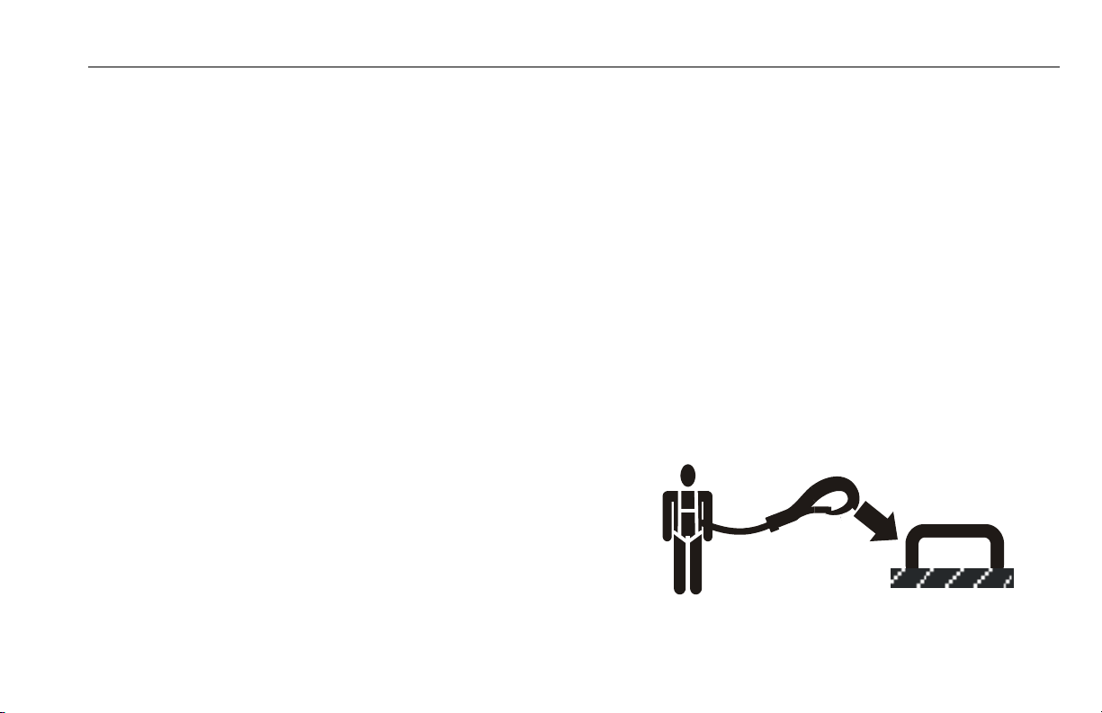
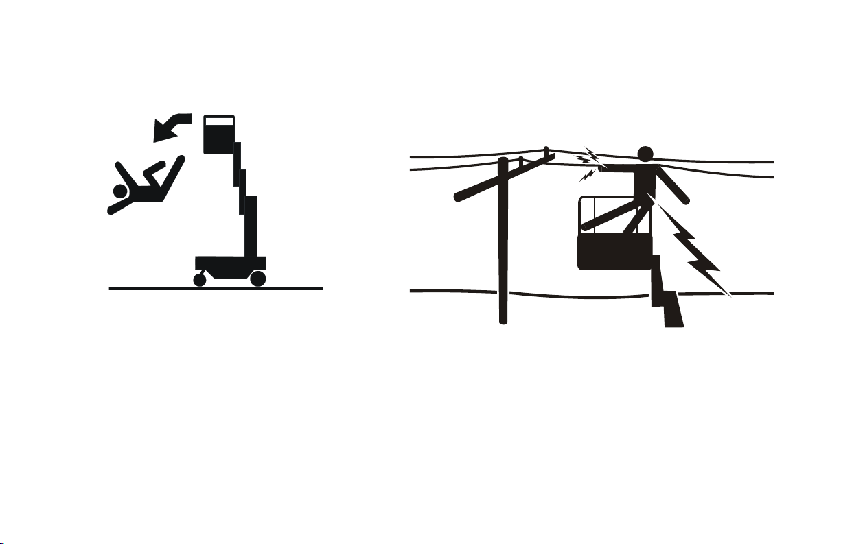
Trip and Fall Hazard
• JLG Industries, Inc. recommends that the operator in the
platform wear approved fall protection attached to an
authorized lanyard anchorage point. Reference “StockPicking Platform Operation” on page 28 for fall protection
requirements applicable to stockpicker platforms operated with the rails in the open position. For further information regarding fall protection requirements on JLG
products, contact JLG Industries, Inc.
3121230 – JLG Lift – 1-3
Page 14
SECTION 1 - SAFETY PRECAUTIONS
• Before operating the machine, make sure all railing and
gates are fastened in their proper position.
• Keep both feet firmly positioned on the platform floor at all
times. Never use ladders, boxes, steps, planks, or similar
items on platform to provide additional reach.
• Never use the mast assembly to enter or leave the platform.
• Use extreme caution when entering or leaving platform.
Ensure that the mast assembly is fully lowered. Face the
machine when entering or leaving the platform. Always
maintain “three point contact” with the machine, using two
hands and one foot or two feet and one hand at all times
during entry and exit.
Electrocution Hazards
• This machine is not insulated and does not provide protection from contact or proximity to electrical current.
• Maintain distance from electrical lines, apparatus, or any
energized (exposed or insulated) parts according to the
Minimum Approach Distance (MAD) as shown in Table 1-
1.
• Allow for machine movement and electrical line swaying.
1-4 – JLG Lift – 3121230
Page 15
SECTION 1 - SAFETY PRECAUTIONS
Table 1-1. Minimum Approach Distances (M.A.D.)
Voltage Range
(Phase to Phase)
0 to 50 KV 10 (3)
Over 50KV to 200 KV 15 (5)
Over 200 KV to 350 KV 20 (6)
Over 350 KV to 500 KV 25 (8)
Over 500 KV to 750 KV 35 (11)
Over 750 KV to 1000 KV 45 (14)
NOTE: This requirement shall apply except where employer,
local or governmental regulations are more stringent.
• Maintain a clearance of at least 10 ft. (3m) between any
part of the machine and its occupants, their tools, and
their equipment from any electrical line or apparatus carrying up to 50,000 volts. One foot additional clearance is
required for every additional 30,000 volts or less.
• The minimum approach distance may be reduced if insulating barriers are installed to prevent contact, and the
barriers are rated for the voltage of the line being guarded.
These barriers shall not be part of (or attached to) the
machine. The minimum approach distance shall be
reduced to a distance within the designed working dimensions of the insulating barrier. This determination shall be
MINIMUM APPROACH DISTANCE
in Feet (Meters)
made by a qualified person in accordance with the
employer, local, or governmental requirements for work
practices near energized equipment
DO NOT MANEUVER MACHINE OR PERSONNEL INSIDE PROHIBITED
ZONE (MAD). ASSUME ALL ELECTRICAL PARTS AND WIRING ARE
ENERGIZED UNLESS KNOWN OTHERWISE.
3121230 – JLG Lift – 1-5
Page 16
SECTION 1 - SAFETY PRECAUTIONS
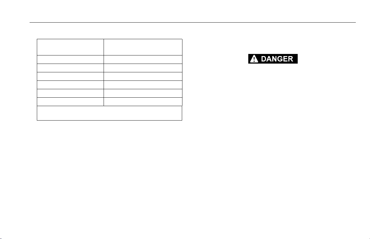
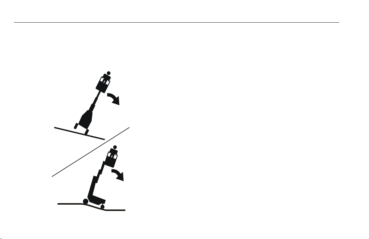
Tipping Hazard
• The user should be familiar with the surface before driving. Do not exceed the allowable sideslope and grade
while driving.
• Do not elevate platform or drive with platform elevated
while on a slope, or on an uneven or soft surface.
• Before driving on floors, bridges, trucks, and other surfaces, check allowable capacity of the surfaces.
• Never exceed the maximum platform capacity. Distribute
loads evenly on platform floor.
• Keep the chassis of the machine a minimum of 2 ft. (0.6m)
from holes, bumps, drop-offs, obstructions, debris, concealed holes, and other potential hazards at the ground
level.
• Never attempt to use the machine as a crane. Do not tieoff machine to any adjacent structure.
• Do not increase the platform size with unauthorized deck
extensions or attachments, increasing the area exposed
to wind will decrease stability.
• If mast assembly or platform is caught so that one or more
wheels are off the ground, the operator must be removed
before attempting to free the machine. Use cranes, forklift
trucks, or other appropriate equipment to stabilize
machine and remove personnel.
1-6 – JLG Lift – 3121230
Page 17
SECTION 1 - SAFETY PRECAUTIONS
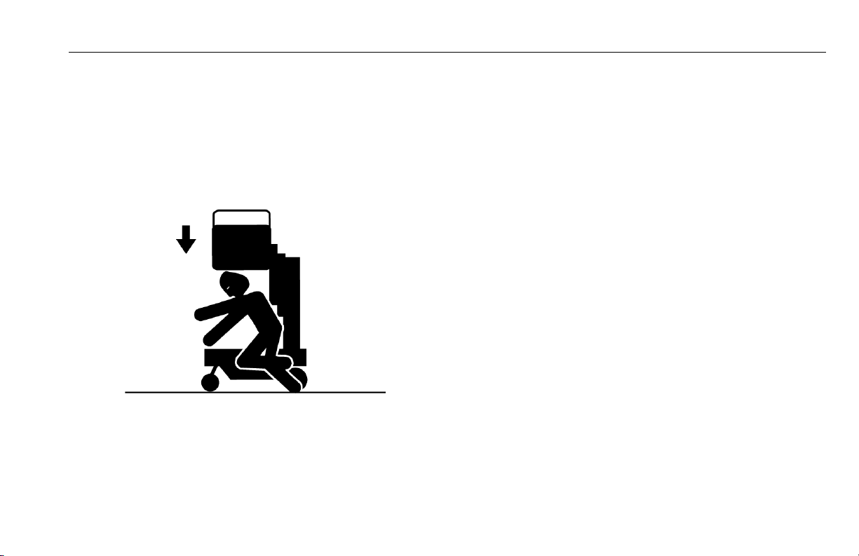
Crushing And Collision Hazard
• Personal protection equipment must be worn by all operating and ground personnel.
• Check work area clearances above, on sides, and bottom
of platform while driving and lifting or lowering platform.
• During operation, keep all body parts inside platform railing.
• Always post a lookout when driving in areas where vision
is obstructed.
• Keep non-operating personnel at least 6 ft. (1.8m) away
from machine during all driving operations.
• Limit travel speed according to conditions of ground surface, congestion, visibility, slope, location of personnel,
and other factors causing hazards of collision or injury to
personnel.
• Be aware of stopping distances in all drive speeds.
• Do not drive at high speeds in restricted or close quarters
or when driving in reverse.
• Exercise extreme caution at all times to prevent obstacles
from striking or interfering with operating controls and persons in the platform.
• Ensure that operators of other overhead and floor level
machines are aware of the aerial work platform’s presence. Disconnect power to overhead cranes.
• Warn personnel not to work, stand, or walk under a raised
platform. Position barricades on floor as necessary.
3121230 – JLG Lift – 1-7
Page 18

SECTION 1 - SAFETY PRECAUTIONS
1.4 Towing, Lifting, And Hauling
• Never allow personnel in platform while towing, lifting, or
hauling.
• This machine should not be towed, except in the event of
emergency, malfunction, power failure, or loading/unloading. Refer to the Emergency Procedures Section of this
manual for emergency towing procedures.
• Ensure platform is fully retracted and completely empty of
tools prior to towing, lifting or hauling.
• Do not assist a stuck or disabled machine by pushing or
pulling except by pulling at the chassis tie-down bars.
• When lifting machine with a forklift, position forks only at
designated areas of the machine. Lift with a forklift of adequate capacity.
• Refer to the Machine Operation section of this manual for
lifting information.
1-8 – JLG Lift – 3121230
Page 19

SECTION 2 - PREPARATION AND INSPECTION
SECTION 2. PREPARATION AND INSPECTION
2.1 PERSONNEL TRAINING
The aerial platform is a personnel handling device; so it is necessary that it be operated and maintained only by trained personnel.
Persons under the influence of drugs or alcohol or who are subject
to seizures, dizziness or loss of physical control must not operate
this machine.
Operator Training
Operator training must cover:
1. Use and limitations of the controls in the platform and at
the ground, emergency controls and safety systems.
2. Control labels, instructions, and warnings on the
machine.
3. Rules of the employer and government regulations.
4. Use of approved fall protection device.
5. Enough knowledge of the mechanical operation of the
machine to recognize a malfunction.
6. The safest means to operate the machine where overhead obstructions, other moving equipment, and obstacles, depressions, holes, drop-offs are present.
7. Means to avoid the hazards of unprotected electrical
conductors.
8. Specific job requirements or machine application.
3121230 – JLG Lift – 2-1
Page 20

SECTION 2 - PREPARATION AND INSPECTION
Training Supervision
Training must be done under the supervision of a qualified person
in an open area free of obstructions until the trainee has developed the ability to safely control and operate the machine.
Operator Responsibility
The operator must be instructed that he/she has the responsibility
and authority to shut down the machine in case of a malfunction or
other unsafe condition of either the machine or the job site.
NOTE: The Manufacturer or Distributor will provide qualified peo-
ple for training assistance with the first unit(s) delivered
and from that time forward as requested by the user or
his/her personnel.
2.2 PREPARATION, INSPECTION, AND MAINTENANCE
The following table covers the periodic machine inspections and
maintenance recommended by JLG Industries, Inc. Consult local
regulations for further requirements for aerial work platforms. The
frequency of inspections and maintenance must be increased as
necessary when the machine is used in a harsh or hostile environment, if the machine is used with increased frequency, or if the
machine is used in a severe manner.
2-2 – JLG Lift – 3121230
Page 21
SECTION 2 - PREPARATION AND INSPECTION
NOTICE
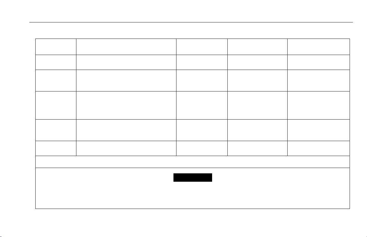
Table 2-1. Inspection and Maintenance Table
TYPE FREQUENCY
Pre-Start
Inspection
Pre-Delivery
Inspection
(See Note)
Frequent
Inspection
Annual Machine
Inspection
Preventative
Maintenance
NOTE: Inspection forms are available from JLG. Use the Service and Maintenance Manual to perform inspections.
JLG INDUSTRIES, INC. RECOGNIZES A QUALIFIED JLG MECHANIC AS A PERSON WHO HAS SUCCESSFULLY COMPLETED THE JLG SERVICE
TRAINING SCHOOL FOR THE SPECIFIC JLG PRODUCT MODEL.
Before using each day; or
whenever there’s an Operator change.
Before each sale, lease, or rental delivery. Owner, Dealer, or User Qualified JLG Mechanic Service and Maintenance
In service for 3 months or 150 hours, whichever
comes first; or;
Out of service for a period of more tha n 3 months; or
Purchased used.
Annually, no later than 13 months from the date of
prior inspection.
At intervals as specified in the Service and Maintenance Manual.
PRIMARY
RESPONSIBILITY
User or Operator User or Operator Operator and Safety Manual
Owner, Dealer, or User Qualified JLG Mechanic Service and Maintenance
Owner, Dealer, or User Qualified JLG Mechanic
(Recommended)
Owner, Dealer, or User Qualified JLG Mechanic Service and Maintenance
SERVICE
QUALIFICATION
REFERENCE
Manual and applicable JLG
inspection form
Manual and applicable JLG
inspection form
Service and Maintenance
Manual and applicable JLG
inspection form
Manual
3121230 – JLG Lift – 2-3
Page 22
SECTION 2 - PREPARATION AND INSPECTION
2.3 PRE-START INSPECTION
The Pre-Start Inspection should include each of the following:
1. Cleanliness – Check all surfaces for leakage (oil, fuel,
or battery fluid) or foreign objects. Report any leakage to
the proper maintenance personnel.
2. Decals and Placards – Check all for cleanliness and
legibility. Make sure no decals or placards are missing.
Make sure all illegible decals and placards are cleaned
or replaced. (Reference "Decal Installations" in Section
3).
3. Operators and Safety Manuals – Make sure a copy of
the Operator and Safety Manual, EMI Safety Manual
(Domestic only), and ANSI Manual of Responsibilities
(Domestic only) is enclosed in the weather resistant
storage container.
4. Daily Walk-Around Inspection – (See Section 2.4)
5. Battery – Charge as required.
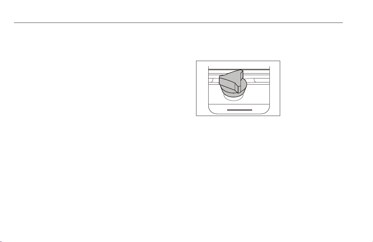
6. Hydraulic Oil – Check the hydraulic oil level.
NOTE: Check Service Manual for instructions and hydraulic oil
specification before adding. DO NOT OVERFILL.
FILL TO LINE
on Hydraulic
Reservoir
indicates the
proper level for
hydraulic oil.
7. Function Check – Check all machine controls for operation per Section 2.5, Function Check.
If optional equipment is installed on this machine refer to Section 3
for specific Pre-Start Inspection and Operation instructions.
2-4 – JLG Lift – 3121230
Page 23

SECTION 2 - PREPARATION AND INSPECTION
2.4 DAILY WALK-AROUND INSPECTION
Begin the “Walk-Around Inspection” at item one (1) as noted on
the diagram. Continue around machine check each item in
sequence for the conditions listed in the following check list.
TO AVOID POSSIBLE INJURY, BE SURE MACHINE POWER IS “OFF”
DURING “WALK-AROUND INSPECTION”.
DO NOT OPERATE MACHINE UNTIL ALL MALFUNCTIONS HAVE BEEN
CORRECTED.
DO NOT OVERLOOK VISUAL INSPECTION OF THE BASE FRAME
UNDERSIDE. CHECK THIS AREA FOR OBJECTS OR DEBRIS WHICH
COULD CAUSE EXTENSIVE MACHINE DAMAGE.
INSPECTION NOTE: On all components, make sure there are no
loose or missing parts, that they are securely fastened, and that no
visible damage, leaks or excessive wear exists in addition to any
other criteria mentioned.
1. Drive and Caster Wheels - Check for any debris stuck
to or around wheels.
2. Base Frame - Check pot-hole-protection system components; check for loose wires or cables dangling below
the base.
3. Manual Descent Control Valve - See inspection note
above.
4. Motor/Pump/Reservoir Unit - No evidence of hydraulic
leaks. Hydraulic oil level should be filled level with the
full line.
5. Batteries - Charge if necessary.
6. Platform Assembly and Gate - Quick-Change platform
mounting and mounting pins; platform railings; entry bar
or gate in proper working order; MSP - platform fasteners.
7. Platform Control Console - Platform control; placards
secure and legible; emergency stop switch reset for
operation; Control markings legible.
8. Ground Control Station - Main Power Selector Switch
operable; placards secure and legible; emergency stop
switch operates properly.
9. Mast Assembly - Mast sections; slide pads; mast
chains; sequencing cables; platform control and power
cables (on side of mast); power cables properly tensioned and seated in sheaves; cable sheaves rotating
freely.
3121230 – JLG Lift – 2-5
Page 24
SECTION 2 - PREPARATION AND INSPECTION
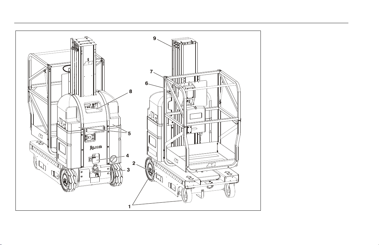
1. Drive and Caster Wheels
2. Base Frame
3. Manual Descent Control Valve
4. Motor/Pump/Reservoir Unit
5. Batteries - (Inside Cover)
6. Platform Assembly
7. Platform Control Console
8. Ground Control Station
9. Mast Assembly
Figure 2-1. Daily Walk-Around Inspection for MVL/MSP Machines.
2-6 – JLG Lift – 3121230
Page 25
2.5 Function Check
Once the “Walk-Around” Inspection is complete, perform a function check of all systems in an area free of overhead and ground
level obstructions. Refer to Section 3 for more specific operating
instructions.
SECTION 2 - PREPARATION AND INSPECTION
IF THE MACHINE DOES NOT OPERATE PROPERLY, TURN OFF THE
MACHINE IMMEDIATELY! REPORT THE PROBLEM TO THE PROPER
MAINTENANCE PERSONNEL. DO NOT OPERATE THE MACHINE UNTIL
IT IS DECLARED SAFE FOR OPERATION.
Perform a Function Check as follows:
1. From the ground controls with no load in the platform:
a. Operate ground control functions, platform lift up
and lift down.
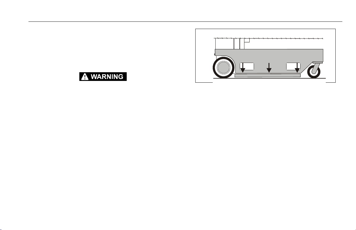
b. Ensure Pot-Hole-Protection device is fully engaged
(bars down on sides) when the platform is elevated
(See Figure 2-2.).
c. Ensure that all machine functions are disabled
when the Emergency Stop Button is activated.
d. Check Manual Descent Control valve is operating
properly.
Figure 2-2. Pot-Hole-Protection Bars Lowered.
2. From the platform control console:
a. Ensure that the control console is properly mounted
and secure.
b. Raise and lower platform 2 ft. to 3 ft. (.61m to .92 m)
several times. Check for smooth elevation and lowering of platform.
c. Operate all functions, check all limit, cut-out, and
enable switches are functioning properly:
• Machine Brakes - Drive the machine on a
grade, (do not exceed the rated gradability),
and stop to ensure the brakes hold.
• Tilt Warning Limit - With the platform completely lowered, drive the machine onto a surface with a tilt of more than 1.5° in any direction
(do not exceed rated gradability). The
3121230 – JLG Lift – 2-7
Page 26

SECTION 2 - PREPARATION AND INSPECTION
machine will indicate a tilt condition if any
attempt is made to elevate the platform.
• Drive Speed Reduction Limit - When platform
is elevated more than 1.5 to 2 ft. (.5m) drive
speed is cut to 1/4 of platform lowered drive
speed.
• Platform Joystick Enable Trigger - The
machine will not operate (drive or lift) unless this
switch is pressed and held during drive or lift
operation.
d. Ensure all machine functions are disabled when the
Emergency Stop Button is activated (pressed in).
2-8 – JLG Lift – 3121230
Page 27

SECTION 3 - MACHINE CONTROLS, INDICATORS AND OPERATION
SECTION 3. MACHINE CONTROLS, INDICATORS AND OPERATION
3.1 GENERAL
THE MANUFACTURER HAS NO DIRECT CONTROL OVER MACHINE APPLICATION AND OPERATION. THE USER AND OPERATOR ARE RESPONSIBLE
FOR CONFORMING WITH GOOD SAFETY PRACTICES.
This section provides the necessary information needed to
understand control function and operation.
3.2 MACHINE DESCRIPTION
The JLG MVL/MSP Model Lifts are electric self-propelled
machines with an aerial work platform mounted to an elevating
aluminum mast mechanism. The personnel lift’s intended purpose
is to provide personnel access to areas above ground level. The
MSP model lift is intended for stock picking purposes in retail
stores or warehouses.
The primary control station is located in the platform. From the
Platform Control Console the operator can drive the machine and
raise or lower the platform.
The controls of the programmable Ground Control Station are to
be used during machine power-up, machine maintenance or in
case of emergency should the operator in the platform be unable
to lower the platform.
Vibrations emitted by these machines are not hazardous to an
operator working in the platform.
The continuous A-Weighted sound pressure level at the work platform is less than 70db (A).
3121230 – JLG Lift – 3-1
Page 28

SECTION 3 - MACHINE CONTROLS, INDICATORS AND OPERATION
3.3 MACHINE OPERATION
Getting Started
The following control conditions must be met before the machine
can be operated from either the Ground or Platform Controls.
• The batteries contain enough voltage to operate the
machine.
• The Main Power Selector Switch on the Ground Control Station must be set for either Ground Control Mode or Platform
Control Mode.
• Both Emergency Stop Switches, one on the Ground Control
Station the other on the Platform Control Console must be in
the RESET position.
• If equipped, the On/Off Key Switch on the Platform Console
must be set to the ON position.
3.4 BATTERY CHARGING
This machine is equipped with an AC voltage input/DC voltage
output battery charger. The charger automatically terminates
charging when the batteries reach full capacity.
NOTE: The platform drive function is disabled when the battery
charger is plugged into an AC receptacle.
LEAD ACID BATTERIES MAY GENERATE EXPLOSIVE HYDROGEN GAS
DURING NORMAL OPERATION. KEEP SPARKS, FLAMES, AND SMOKING MATERIALS AWAY FROM BATTERIES. PROVIDE ADEQUATE VENTILATION DURING CHARGING. NEVER CHARGE A FROZEN BATTERY.
STUDY ALL BATTERY MANUFACTURERS’ SPECIFIC PRECAUTIONS
SUCH AS RECOMMENDED RATES OF CHARGE AND REMOVING OR
NOT REMOVING CELL CAPS WHILE CHARGING.
3-2 – JLG Lift – 3121230
Page 29
SECTION 3 - MACHINE CONTROLS, INDICATORS AND OPERATION
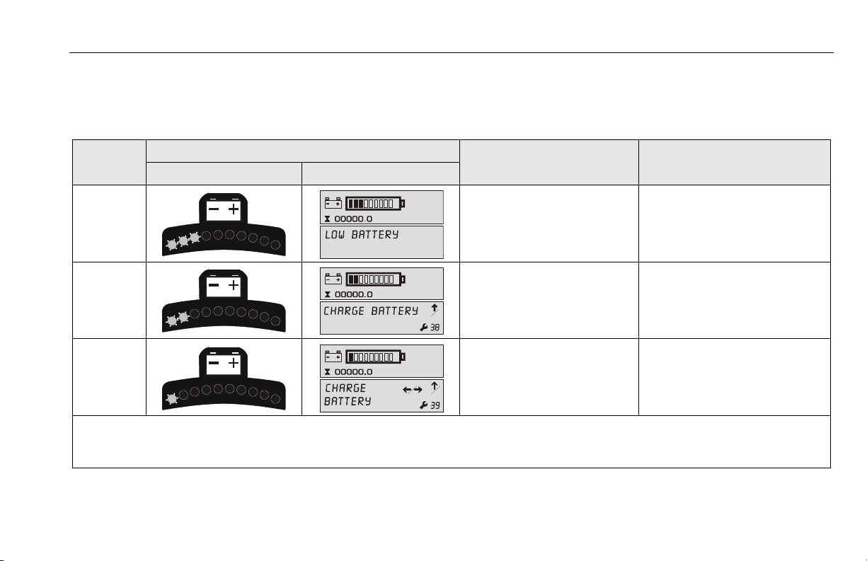
Battery - Low Voltage Warning Indicators
The MVL/MSP Platform Control Console and Ground Control Station indicate battery low voltage at three (3) Warning Levels.
Table 3-1. Battery Low Voltage Warning Indicators.
WARNING
LEVEL
LEVEL-1
LEVEL-2
LEVEL-3
NOTE: (a) To maximize battery life, it is recommended that the factory supplied batteries be charged continuously for a minimum of 4 hours or until 8
PLATFORM CONTROL LED GROUND CONTROL LCD
bars are lit on the ground station LCD Display before operating the machine. When drained to Warning Level 2 or 3, batteries must be charged
until 8 bars are lit on the ground station LCD display to clear the fault code.
INDICATOR LOCATION
RESULT
• 3 LEDs/BARS Flashing with an
audible beep.
• Machine will Operate - No Control Functions Locked Out.
• 2 LEDs/BARS Flashing with an
audible beep.
• Platform Lift-UP Function is
Locked Out.
• 1 LED/BAR Flashing with an
audible beep.
• Drive and Platform Lift-UP
Functions Locked Out.
ACTION REQUIRED TO CLEAR
FAULT
Charge batteries to a level of four (4)
LEDs/BARS or more before operating.
Charge batteries for a minimum of four
(4) continuous hours or eight (8)
LEDs/BARS lit before operating. (a)
Charge batteries for a minimum of four
(4) continuous hours or eight (8)
LEDs/BARS lit before operating. (a)
3121230 – JLG Lift – 3-3
Page 30
SECTION 3 - MACHINE CONTROLS, INDICATORS AND OPERATION
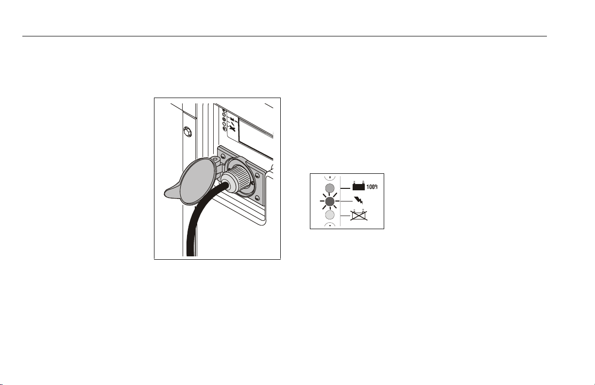
To Charge Batteries
1. Park machine in a well ventilated area near an AC voltage
electrical outlet.
2. Always use a grounded
AC outlet. Connect charger to an outlet that has
been properly installed
and grounded in accordance with all local codes
and ordinances. A
grounded outlet is
required to reduce risk of
electric shock – do not
use ground adapters or
modify plug. When using
an extension cord, avoid
excessive voltage drops
by using a grounded 3wire 12 AWG cord.
Battery Charging Status Indicators
The battery charging status indicators are located just above the
Charger AC input receptacle on the center cover section at the
rear of the machine. (See Figure 3-1. on page 3-8)
1. When plugged in the charger will automatically turn on and
run through a short LED indicator self-test (all LED’s will flash
in an up-down sequence for two seconds).
2. The YELLOW ‘CHARGING’ LED will turn on and a trickle current will be applied until a minimum voltage is reached.
CHARGING
YELLOW (MIDDLE) LED ON
Charge Incomplete
Once a minimum battery voltage of 2 volts per cell is
detected, the charger will enter the bulk charging constantcurrent stage and the YELLOW ‘CHARGING’ LED will remain
on. The length of charge time will vary by how large and how
depleted the battery pack is, the input voltage (the higher,
the better), and ambient temperatures (the lower, the better).
If the input AC voltage is low (below 104VAC), then the
charging power will be reduced to avoid high input currents.
If the ambient temperature is too high, then the charging
3-4 – JLG Lift – 3121230
Page 31

SECTION 3 - MACHINE CONTROLS, INDICATORS AND OPERATION
power will also be reduced to maintain a maximum internal
temperature.
3. When the GREEN ‘CHARGED’ LED turns on, the batteries
are completely charged.
CHARGE COMPLETE
GREEN (TOP) LED ON
100% Complete
The charger may now be unplugged from AC power (always
pull on plug and not cord to reduce risk of damage to the
cord). If left plugged in, the charger will automatically restart
a complete charge cycle if the battery pack voltage drops
below a minimum voltage or 30 days has elapsed.
4. If a fault occurred anytime during charging, a fault indication
is given by flashing the RED ‘FAULT’ LED with a code corresponding to the error.
CHARGING PROBLEM
RED (BOTTOM) LED ON
See Flash Codes following
There are several possible conditions that generate errors.
Some errors are serious and require human intervention to
first resolve the problem and then to reset the charger by
interrupting AC power for at least 10 seconds. Others may be
simply transient and will automatically recover when the fault
condition is eliminated. To indicate which error occurred, the
RED ‘FAULT’ LED will flash a number of times, pause, and
then repeat.
[1 FLASH] Battery Voltage High: auto-recover. Indicates a
high battery pack voltage.
[2 FLASH] Battery Voltage Low: auto-recover. Indicates
either a battery pack failure, battery pack is not connected to
charger, or battery volts per cell is less than 0.5 VDC. Check
the battery pack and battery pack connections.
3121230 – JLG Lift – 3-5
Page 32

SECTION 3 - MACHINE CONTROLS, INDICATORS AND OPERATION
[3 FLASH] Charge Timeout: Indicates the battery did not
charge within the allowed time. This could occur if the battery is of a larger capacity than the algorithm is intended for.
It can also occur if the battery pack is damaged, old, or in
poor condition. In unusual cases it could mean charger output is reduced due to high ambient temperature.
[4 FLASH] Check Battery: Indicates the battery pack could
not be trickle charged up to the minimum 2 volts per cell
level required for the charge to be started. This may also
indicate that one or more cells in the battery pack are
shorted or damaged.
[5 FLASH] Over-Temperature: auto-recover. Indicates charger has shutdown due to high internal temperature which
typically indicates there is not sufficient airflow for cooling –
see step 1 of Installation Instructions. Charger will restart and
charge to completion if temperature is within accepted limits.
[6 FLASH] QuikQ Fault: Indicates that the batteries will not
accept charge current, or an internal fault has been detected
in the charger. This fault will nearly always be set within the
first 30 seconds of operation. Once it has been determined
that the batteries and connections are not faulty and Fault 6
is again displayed after interrupting AC power for at least 10
seconds, the charger must be brought to a qualified service
depot.
3-6 – JLG Lift – 3121230
Page 33

SECTION 3 - MACHINE CONTROLS, INDICATORS AND OPERATION
3.5 GROUND CONTROL STATION - OPERATION
(See Figure 3-1.)
NOTE: If equipped with optional Programmable Security Lock
(PSL) see Section 3.12 for additional instructions.
Main Power Selector Switch
Set the Main Power Selector
Switch to Ground Control Mode
for Ground Control operation or
Platform Control Mode for Platform Operation.
Emergency Stop/Shut Down Button
POWER OFF
PUSH IN -
To Engage
Emergency Stop
POWER ON
TURN CLOCKWISE
and RELEASE -
To R es et
Emergency Stop
Brake Release Button
DO NOT MANUALLY DISENGAGE THE BRAKES UNLESS MACHINE IS SETTING ON A LEVEL SURFACE OR MACHINE IS FULLY RESTRAINED.
PUSH and RELEASE TO DISENGAGE Brakes
PUSH and RELEASE AGAIN TO ENGAGE Brakes
NOTE: The brakes only DISENGAGE (electrically) when the joy-
stick control is moved off center during driving or are
manually DISENGAGED (electrically) using the the Brake
Release Button.
If the machine’s batteries are completely depleted of
electrical charge the brakes cannot be released manually.
3121230 – JLG Lift – 3-7
Page 34

SECTION 3 - MACHINE CONTROLS, INDICATORS AND OPERATION
Ground Control Module
1. Machine Status LCD Display
2. Main Power Selector Switch
3. Emergency Stop
4. Brake Release
5. Platform Up
6. Platform Down
Battery Charging Station
7. Battery Charging Status Indicators
8. Charger A/C Input Receptacle
Hydraulic System
9. Hydraulic Oil Reservoir
10. Manual Descent Control Valve
NOTE: The Ground Control Station Module is fully pro-
grammable. For operator level programmability
see Section 5.4, GROUND CONTROL STATION PROGRAMMING.
NOTE: If equipped with optional Programmable Security
Lock (PSL) see Section 3.12 on page 3-36 for
additional machine power-up instructions.
Figure 3-1. Ground Control Station. (Machine Rear View)
3-8 – JLG Lift – 3121230
Page 35

SECTION 3 - MACHINE CONTROLS, INDICATORS AND OPERATION
Platform Up
Platform Down
PUSH IN TO ELEVATE Platform
RELEASE TO STOP ELEVATING
PUSH IN TO LOWER Platform
RELEASE TO STOP LOWERING
Manual Descent Control Valve
PUSH-IN TO
LOWER Platform
RELEASE TO STOP Platform
Descent
3121230 – JLG Lift – 3-9
Page 36
SECTION 3 - MACHINE CONTROLS, INDICATORS AND OPERATION
3
5
4
1
2
00
00
00000.0
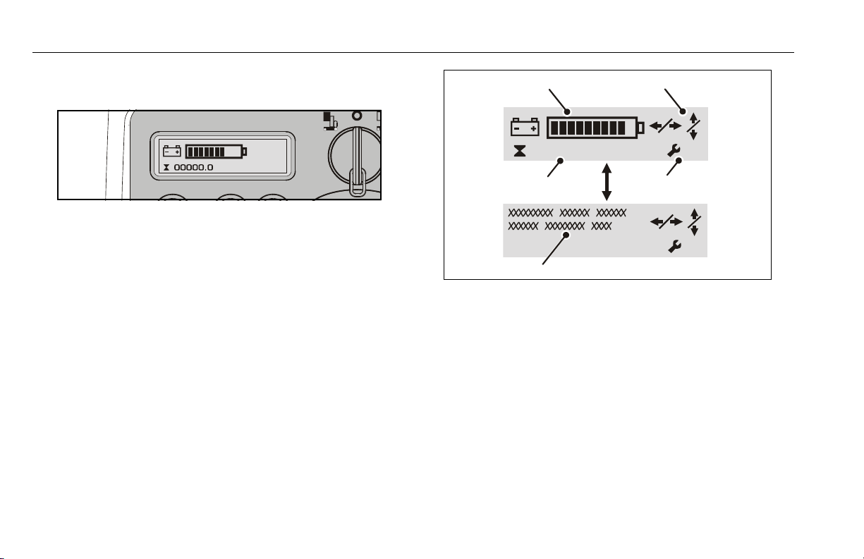
Machine Status LCD Display
At power-up and during operation the LCD display on the Ground
Control Module displays the current machine operating status.
The following illustration explains the symbol indications.
Note: (a) When an Fault Code is indicated the LCD screen will
LCD Display Symbols
1. Battery Charge Indicator (BCI)
2. Function Display or Function Disabled Indicators
3. Hour Meter Display
4. Fault Code Indicator
5. Fault Text Message Display (a)
alternate between the text and symbol display modes.
3-10 – JLG Lift – 3121230
Page 37
SECTION 3 - MACHINE CONTROLS, INDICATORS AND OPERATION
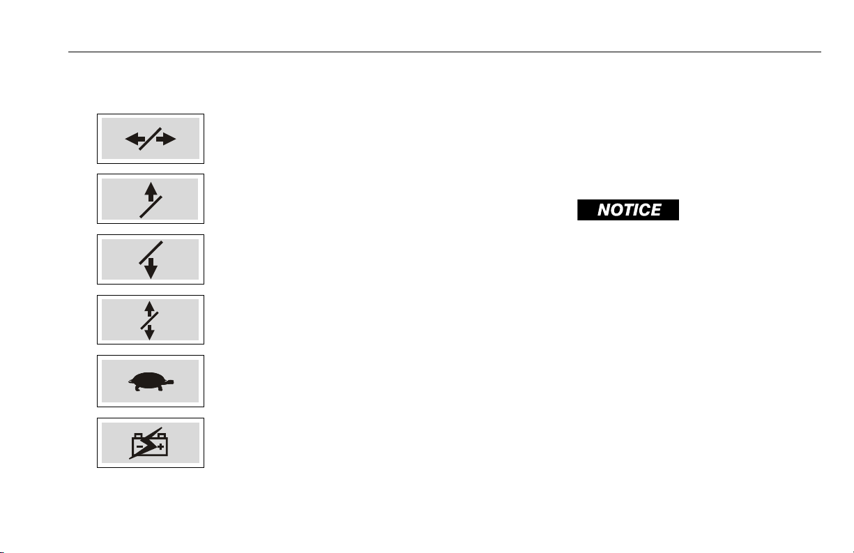
In the LCD Display Symbols illustration item (2), the Function Display or Function Disabled Indicators will vary as shown following:
DRIVE Disabled
LIFT UP Disabled
LIFT DOWN Disabled
Both LIFT UP and LIFT DOWN
Disabled
Drive Speed Cut-Back Turtle) Mode Engaged
(When Platform is Elevated)
Battery Charger (AC) Plugged In
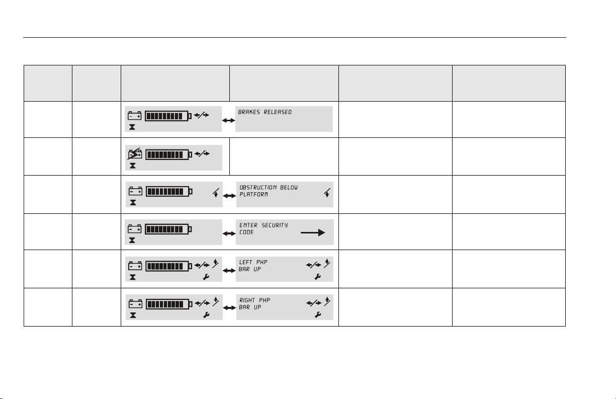
LCD Display Fault Conditions
Table 3-2, LCD Display - Operation Fault Conditions show common LCD display Fault indications which may occur during operation and are usually caused by either an error in machine
operation or a work area condition. These fault conditions can
usually be corrected by the operator and do not require a qualified
mechanic to repair.
AFTER A FAULT CONDITION IS CORRECTED THE MACHINE POWER MAY
NEED TO BE RECYCLED TO RESET THE GROUND CONTROL STATION.
3121230 – JLG Lift – 3-11
Page 38
SECTION 3 - MACHINE CONTROLS, INDICATORS AND OPERATION
00000.0
00000.0
00000.0
00000.0
02
02
00000.0
03
03
00000.0
Table 3-2. LCD Display - Operation Fault Conditions
FAULT
CODE
PLATFORM
LEDS
FLASHING
LCD SYMBOL SCREEN LCD TEXT SCREEN
——
— — NONE
——
——
22
32
FAULT DESCRIPTION/
MACHINE CONDITION
Brakes Released
(DRIVE Disabled)
Charger AC Plugged In
DRIVE Disabled
Obstruction Sensor System
(Platform Elevated)
LIFT DOWN Disabled
Programmable Security
Lock Password
Left PHP Bar UP
(Platform Elevated)
DRIVE and Lift UP Disabled
Right PHP Bar UP
(Platform Elevated)
DRIVE and Lift UP Disabled
LOOK FOR THIS
To Engage Brakes - Press Brake
Release Button on Ground Control Station
Unplug Charger AC Power Cord
Obstruction Under Platform or
Sensor Defective
Enter Code on PSL Keypad to
Power-Up Machine
Lower Platform and Check the
Left Pot Hole Protection Bar
Lower the Platform and Check
the Right Pot Hole Protection Bar
3-12 – JLG Lift – 3121230
Page 39

SECTION 3 - MACHINE CONTROLS, INDICATORS AND OPERATION
04
04
00000.0
13
13
00000.0
17
17
00000.0
32
32
00000.0
33
33
00000.0
Table 3-2. LCD Display - Operation Fault Conditions (Continued)
FAULT
CODE
PLATFORM
LEDS
FLASHING
43
68
13 6
17 7
32 7
33 2
LCD SYMBOL SCREEN LCD TEXT SCREEN
FAULT DESCRIPTION/
MACHINE CONDITION
Tilt Condition
(Platform Elevated)
DRIVE and Lift UP Disabled
Drive Motor Brush Wear Warning ( 25 hrs. of DRIVE operation
remaining to a 10 sec. shut
down mode)
Tr act io n M od ul e
Over Temperature
(DRIVE Disabled)
Ground Control Module
Over Temperature
(Machine Stopped)
Pump Motor Over Current
(LIFT UP Disabled)
Both PHP Bars UP
DRIVE and Lift UP Disabled
LOOK FOR THIS
Lower the Platform and Drive off
the Tilt Condition
Drive Motor Brushes Require
Service Replacemen t -
(See Section 5.5 on page 5-20
for further Instructions)
Allow Drive System Traction
Module to Cool Before
Operating
Allow Ground Control
Module to Cool Before
Operating
Platform Load Over Capacity
Check for Object Blocking Both
the Left and Right PHP Bars
3121230 – JLG Lift – 3-13
Page 40
SECTION 3 - MACHINE CONTROLS, INDICATORS AND OPERATION
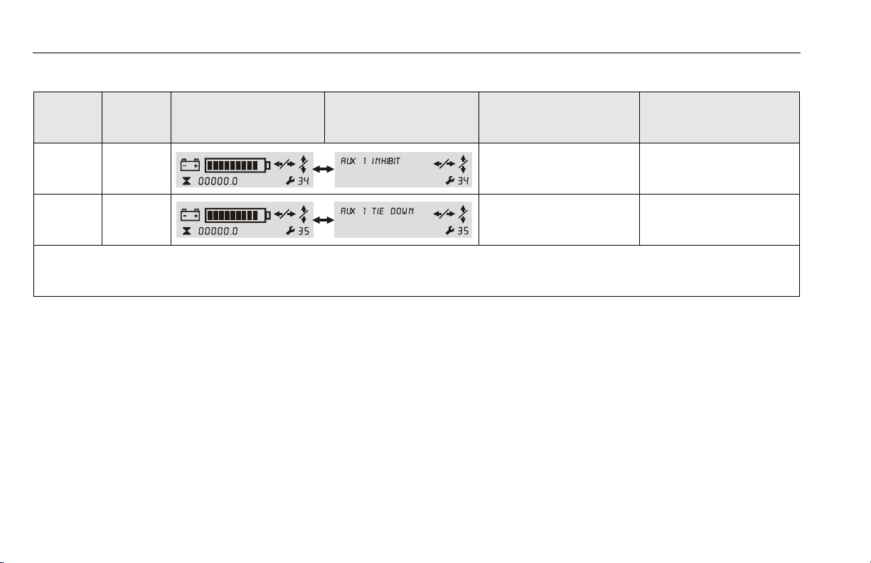
Table 3-2. LCD Display - Operation Fault Conditions (Continued)
FAULT
CODE
34 —
35 —
NOTE: The fault conditions shown above are fault conditions which the Operator may be able to resolve. Should a fault occur and be displayed on the LCD
PLATFORM
LEDS
FLASHING
screen which cannot be corrected at the Operator’s level, the problem must be referred to a qualified JLG mechanic. A complete table of Fault
Codes is listed in the TroubleShooting Section of the Service and Maintenance Manual.
LCD SYMBOL SCREEN LCD TEXT SCREEN
FAULT DESCRIPTION/
MACHINE CONDITION
Aux. #1 - Platform Gate Open or
No Pressure on the Platform
Enable switch.
Aux. #1 - Platform Enable
switch depressed during
Machine Power-up.
LOOK FOR THIS
Close Platform Gate or Depress
Platform Enable switch during
machine operation.
Do Not Press on Platform Enable
switch during Machine PowerUp.
3-14 – JLG Lift – 3121230
Page 41

SECTION 3 - MACHINE CONTROLS, INDICATORS AND OPERATION
1
2
4
5
6
7
8
3
3.6 PLATFORM CONTROL CONSOLE OPERATION
1. On/Off Key Switch (See page 3-16)
2. Emergency Stop/Shut Down Button (See page 3-17)
3. Function Enable Lever - (on front of joystick)
(See page 3-19)
4. Multifunction Joystick Control (See page 3-20)
5. Drive Speed Setting Selector Switch (See page 3-23)
6. Platform Control Display Panel (See page 3-17)
7. Horn Button - (See page 3-19)
8. Drive/Lift Mode Selector Switch -
(See page 3-19)
Figure 3-2. Platform Control Console
3121230 – JLG Lift – 3-15
Page 42

SECTION 3 - MACHINE CONTROLS, INDICATORS AND OPERATION
1
2
General
The following conditions must be met before the machine can be
operated from the platform control console:
• Ground Control Station - Main Power Selector Switch must
be set to PLATFORM CONTROL MODE.
• Ground Control Station - Emergency Stop/Shut Down Button
must be in the RESET position (POWER ON).
NOTE: See Section 3.5 on page 3-7, for Ground Control Station
operation.
• Platform Console - On/Off Key Switch must be set to the ON
position.
• Platform Console - Emergency Stop/Shut Down Button must
be in the RESET position (POWER ON).
• If equipped with the OPTIONAL - PSL (Programmable Secu-
rity Lock - Section 3.12 on page 3-36) it must be set to the
ON position.
NOTE: SLEEP MODE - During operation if no control functions
have been activated for 10 minutes (default programmable setting), the ground control module will power the
machine down to conserve battery power. Cycle power
back on using either the main power selector switch (key)
or the emergency stop/power down button on either the
platform controller or the ground control station.
Platform On/Off Key Switch
At the Platform Control Console Set the On/Off Key Switch to the
ON position (2) to operate
machine.
1. OFF Position
2. ON Position
Set the ON/OFF Key Switch to the OFF position to power machine
down.
NOTE: If necessary, when machine is not in use, remove key
from platform key switch to disable machine from unauthorized use.
NOTE: During operation the operator in the platform can prevent
unauthorized control of the machine (from the Ground
Control Station) by either switching the On/Off Key to the
OFF position, or activating the Emergency Stop Button on
the platform control console.
3-16 – JLG Lift – 3121230
Page 43

SECTION 3 - MACHINE CONTROLS, INDICATORS AND OPERATION
3
1
4
2
Platform Emergency Stop Button
NOTE: The Platform and Ground Control Station Emergency Stop
Buttons must both be in the RESET position to operate
machine.
POWER OFF
PUSH IN TO ENGAGE
Emergency Stop
POWER ON
TURN CLOCKWISE
and RELEASE to
RESET Emergency Stop
Platform Control Display Panel
Figure 3-3. Platform Control Display Panel.
1. Battery Charge/Flash Code
LEDS
2. Drive Mode Indicator
3. Lift Mode Indicator
4. Drive Speed Setting
Indicator
3121230 – JLG Lift – 3-17
Page 44

SECTION 3 - MACHINE CONTROLS, INDICATORS AND OPERATION
1. Battery Charge/Flash Code Indicator LEDS
On normal power-up and operation this series of ten (10)
LEDs visually indicates the amount of charge remaining in
the batteries.
The number of LEDs lit will change depending on the level of
charge in the batteries.
• (+) All Three (3) GREEN LEDs lit up indicate maximum
battery charge.
• Four (4) YELLOW LEDs indicate a two thirds to one third
battery charge remaining.
• (–) Three (3) RED LED’s lit indicate minimum battery
charge remaining. The machine will continue to operate at
this charge level but will begin to indicate low battery voltage warning indicators.
NOTE: For more information on Battery Warning Level Indicators
See “Battery - Low Voltage Warning Indicators” on
page 3-3.
This set of ten (10) LEDs will also indicate a flash (fault) code
if operating problems are detected by the Ground Control
Station. Fault codes are also accompanied by a beeping
alert from the platform control console.
NOTE: LED Flash (Fault) Code indications that can be corrected
by the operator are shown on Table 3-2 on page 3-12, this
section of the manual.
2. Drive Mode Indicator
When the Drive/Lift Mode Selector Switch is set to DRIVE
MODE the round LED indicator on that portion of the display
panel will light up indicating the DRIVE Mode active.
3. Lift Mode Indicator
When the Drive/Lift Mode Selector Switch is set to LIFT
MODE the round LED indicator on that portion of the display
panel will light up indicating the LIFT Mode active.
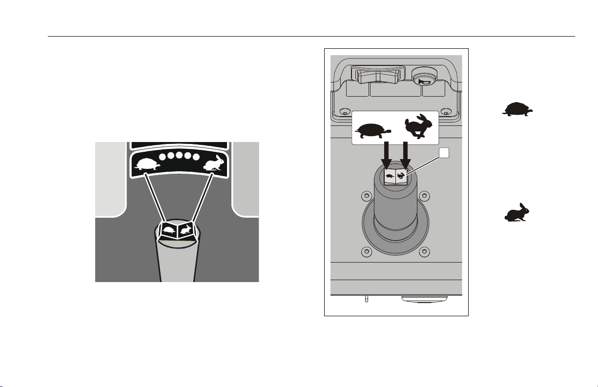
4. Drive Speed Setting Indicator
The five (5) GREEN LEDs on the top of this indicator display
the drive speed setting with the TURTLE (on the left) representing the MINIMUM speed setting and the RABBIT (on the
right) representing the MAXIMUM speed setting.
3-18 – JLG Lift – 3121230
Page 45

SECTION 3 - MACHINE CONTROLS, INDICATORS AND OPERATION
1 2
Drive/Lift Mode Selector Switch Horn Button
Drive/Lift Mode Selector Switch
1. LIFT Mode
2. DRIVE Mode
PUSH the rocker
switch to select mode
of operation.
Whichever mode is
selected the appropriate LED indicator on the
display panel below will
light up showing which
mode has been activated for joystick operation.
IMPORTANT:
The selected mode
will only remain
active for 5 seconds
if the function is not
operated.
When the machine is
powered on, pressing
this button will sound
the Horn.
Joystick Function Enable Lever
The Function Enable lever on
the front of the joystick control, must be engaged and
held in during any joystick
operation.
3121230 – JLG Lift – 3-19
Page 46

SECTION 3 - MACHINE CONTROLS, INDICATORS AND OPERATION
1
Multifunction Joystick Control
The joystick will operate the following machine functions:
• Drive/Steer
•Platform Lift Up and Down
NOTE: Use the Drive/Lift Mode Selector Switch to select which
function the joystick will operate.
The selected operating mode will only remain active for 5
seconds if the function is not operated.
Remember to press and hold the joystick function enable
lever to operate any joystick functions.
SEE FIGURE 3-4. ON PAGE 3-21 FOR GRADE AND SIDESLOPE DRIVING
DESCRIPTION WHEN DRIVING WITH THE PLATFORM LOWERED
(STOWED).
WHEN THE PLATFORM IS ELEVATED DRIVE ONLY ON A SMOOTH,
FIRM, AND LEVEL SURFACE.
Drive Mode
1. Activate the Drive Mode
using the Drive/Lift Mode
Selector switch.
Within 5 seconds of activation - ENGAGE and
HOLD the JOYSTICK
ENABLE LEVER then
move the joystick in the
desired direction of travel.
Drive power is applied
propor tionally the fur ther
the joystick is moved off
center.
3-20 – JLG Lift – 3121230
Page 47

SECTION 3 - MACHINE CONTROLS, INDICATORS AND OPERATION
G
R
A
D
E
SMOOTH, FIRM AND LEVEL
DO NOT DRIVE MACHINE ON A GRADE OR SIDESLOPE EXCEEDING
THOSE SPECIFIED IN SECTION 5 - MACHINE SPECIFICATIONS
SIDESLOPE
3121230 – JLG Lift – 3-21
Figure 3-4. Machine Operating Specifications
Page 48

SECTION 3 - MACHINE CONTROLS, INDICATORS AND OPERATION
2
3
Lift Mode
1. Activate the Lift Mode
using the Drive/Lift Mode
Selector switch.
2. Platform LIFT DOWN
Direction
3. Platform LIFT UP
Direction
Within 5 seconds of activation - ENGAGE and
HOLD the JOYSTICK
ENABLE LEVER then
move the joystick in the
direction of LIFT (3) OR
LOW ER ( 2).
IF THE TILT ALARM WARNING HAS BEEN ACTIVATED WHILE DRIVING
WITH THE PLATFORM ELEVATED, LOWER PLATFORM COMPLETELY
AND DRIVE TO A FIRM LEVEL SURFACE.
ENSURE THE AREA BENEATH THE PLATFORM IS FREE OF PERSONNEL PRIOR TO LOWERING THE PLATFORM.
3-22 – JLG Lift – 3121230
Page 49
SECTION 3 - MACHINE CONTROLS, INDICATORS AND OPERATION
1
Drive Speed Setting Controls
NOTE: When the platform is elevated the maximum drive speed
is automatically cut-back to 1/4th the speed when the
platform is fully lowered. The Ground Control ModuleLCD screen will display a turtle when in this mode, See
page 3-11 - Ground Control - LCD Status Display in this
section of the manual.
Drive Speed Setting
Selector Switch
1. Selector Switch -
(on top of joystick)
Each PRESS on this
side of the switch will
DECREASE maximum
drive speed.
(FEWER LEDs Lit up on
the Drive Speed Indicator.)
Each PRESS on this
side of the switch will
INCREASE maximum
drive speed.
(MORE LEDs Lit up on
the Drive Speed Indicator.)
3121230 – JLG Lift – 3-23
Page 50

SECTION 3 - MACHINE CONTROLS, INDICATORS AND OPERATION
3.7 PARKING MACHINE
1. Drive machine to a well-protected and well-ventilated area.
2. Ensure the platform is fully lowered, turn the main power
selector switch to the OFF position (centered).
NOTE: If required, charge batteries in preparation for next work
day.
3.8 PLATFORM CONFIGURATIONS
The platforms in the following illustrations show the entry points as
well as the direction of the platform gates for opening and closing
when entering the platform. The maximum loading capacities per
model are shown in the tables below each platform as well as the
various components of the platform.
3-24 – JLG Lift – 3121230
Page 51
SECTION 3 - MACHINE CONTROLS, INDICATORS AND OPERATION
2
3
1
FRONT GULL-WING ENTRY PLATFORM (NON-CE and AUS)
1. Front Gull-Wing Entry Gate 3. Lanyard Attach Point -
2. Entry Gate Latch (Left side on mast)
Model Max. Capacity
15MVL 500 lb. (230kg)
20MVL 350 lb. (160kg)
1. Sliding Side Entry Gate 3. Lanyard Attach Point -
2. Platform Control Console (Left side on mast)
FRONT SLIDE BAR ENTRY PLATFORM
Model Max. Capacity
15MVL 500 lb. (230kg)
20MVL 350 lb. (160kg)
3121230 – JLG Lift – 3-25
Page 52

SECTION 3 - MACHINE CONTROLS, INDICATORS AND OPERATION
2
1
3
4
2
Side Entry Platform w/Folding Material Tray Installed
Table 3-3. Max. Capacity with
SIDE ENTRY PLATFORM - w/ FOLDING MATERIAL TRAY
1. Swing Side Entry Gates 3. Platform Control Console
2. Lanyard Attach Point - (on side of 4. Material Tray
mast or lug at right rear upper rail)
SPEC
ANSI/
CSA
CE
AUS
(1)
This platform is only available on models shown for the applicable spec-
ification.
NOTE: Australian Specification Machines ONLY - The SIDE
ENTRY PLATFORM w/FOLDING MATERIAL TRAY
includes a gate release/latch mechanism which is
released by pressing down on the handles mounted to
the top rail of both entry gates. Releasing the handles
will latch the gates when closed.
Model
15MSP
20MSP
20MVL
15MVL
20MVL
(1)
Platform
Capacity
300 lb.
(136 kg)
300 lb.
(136 kg)
250 lb.
(115 kg)
350 lb.
(160 kg)
250 lb.
(115 kg)
Tray Capacity
150 lb.
(70 kg)
150 lb
(70 kg)
100 lb.
(45 kg)
150 lb.
(70 kg)
100 lb.
(45 kg)
Combined
Capacity
450 lb.
(206 kg)
450 lb.
(206 kg)
350 lb.
(160 kg)
500 lb.
(230 kg)
350 lb.
(160 kg)
3-26 – JLG Lift – 3121230
Page 53
SECTION 3 - MACHINE CONTROLS, INDICATORS AND OPERATION
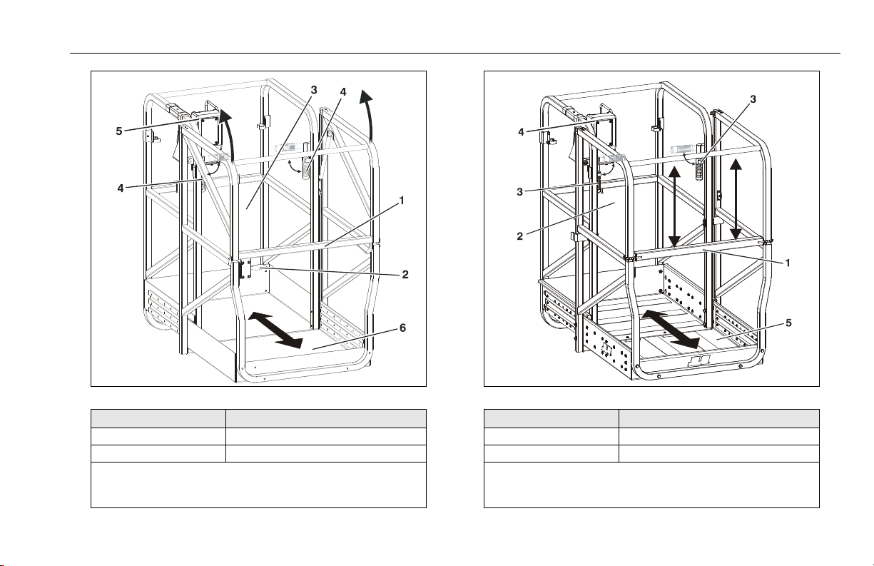
EXTENDIBLE PLATFORM (GULL-WING ENTRY - NON CE and AUS)
Model Max. Capacity
15MVL/15MSP 500 lb. (230 kg)
20MVL/20MSP 350 lb. ( 160kg)
1. Gullwing Entry Gate 4. Extension Slide/Lock Handle
2. Entry Gate Latch 5. Platform Control Console
3. Lanyard Attach Point (on mast) 6. Sliding Extendible Section
EXTENDIBLE PLATFORM (FRONT SLIDE BAR ENTRY - CE ONLY)
Model Max. Capacity
15MVL/15MSP 500 lb. (230 kg)
20MVL/20MSP 350 lb. (16 0kg)
1. Sliding Bar Entry Gate 4. Platform Control Console
2. Lanyard Attach Point (on mast) 5. Sliding Extendible Section
3. Extension Slide/Lock Handle
3121230 – JLG Lift – 3-27
Page 54
SECTION 3 - MACHINE CONTROLS, INDICATORS AND OPERATION
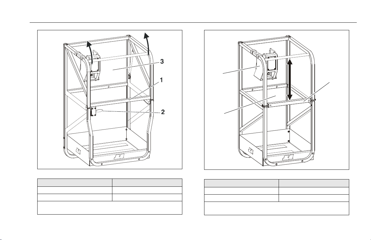
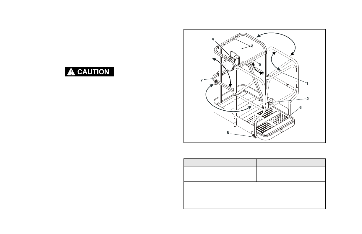
StockPicking Platform Operation
The stockpicking platform is available in two (2) versions.
• Fixed side-rail version
• Folding side-rail version
THE STOCKPICKER PLATFORM ALLOWS THE MACHINE TO BE OPERATED
IN AN OPEN RAIL CONFIGURATION (SEE ILLUSTRATION).
CE SPECIFICATION MACHINES:
THE OPERATOR MUST WEAR A FULL BODY HARNESS EQUIPPED WITH A
LANYARD SHORT ENOUGH TO PREVENT A FALL FROM THE PLATFORM.
THE LANYARD MUST BE ATTACHED TO THE AUTHORIZED LANYARD POINT.
ALSO, JLG RECOMMENDS THAT CE SPECIFICATION MACHINES EQUIPPED
WITH THE STOCKPICKER PLATFORM ARE ONLY TO BE USED FOR STOCKPICKING APPLICATIONS.
NON-CE UNITS:
THE OPERATOR MUST WEAR A FULL BODY HARNESS WITH A LANYARD
(MAX. 6 FT. (1.82M) ATTACHED TO THE AUTHORIZED LANYARD POINT OR
A BODY BELT EQUIPPED WITH A LANYARD SHORT ENOUGH TO PREVENT
A FALL FROM THE PLATFORM.
WHILE OPERATING THE MACHINE IN THE OPEN RAIL CONFIGURATION,
ALWAYS OPERATE THE MACHINE FROM THE REAR OF THE PLATFORM
WITH THE MID-GATE CLOSED AND THE PLATFORM CONTROL CONSOLE
ATTACHED TO THE FIXED PORTION OF THE GUARDRAIL.
1. Primary Entrance/Exit Gate 4. Platform Control Console
2. Primary Entrance Latch 5. Mid-Gate
3. Lanyard Attach Point - 6. Gate Release/Lock Pins
(on mast and platform rail) 7. Secondary Exit Gate
STOCKPICKER PLATFORM
(WITH FOLDING SIDE-RAILS) (MSP)
Model Max. Capacity
15MSP 500 lb. (230 kg)
20MSP 400 lb. (180 kg)
3-28 – JLG Lift – 3121230
Page 55

SECTION 3 - MACHINE CONTROLS, INDICATORS AND OPERATION
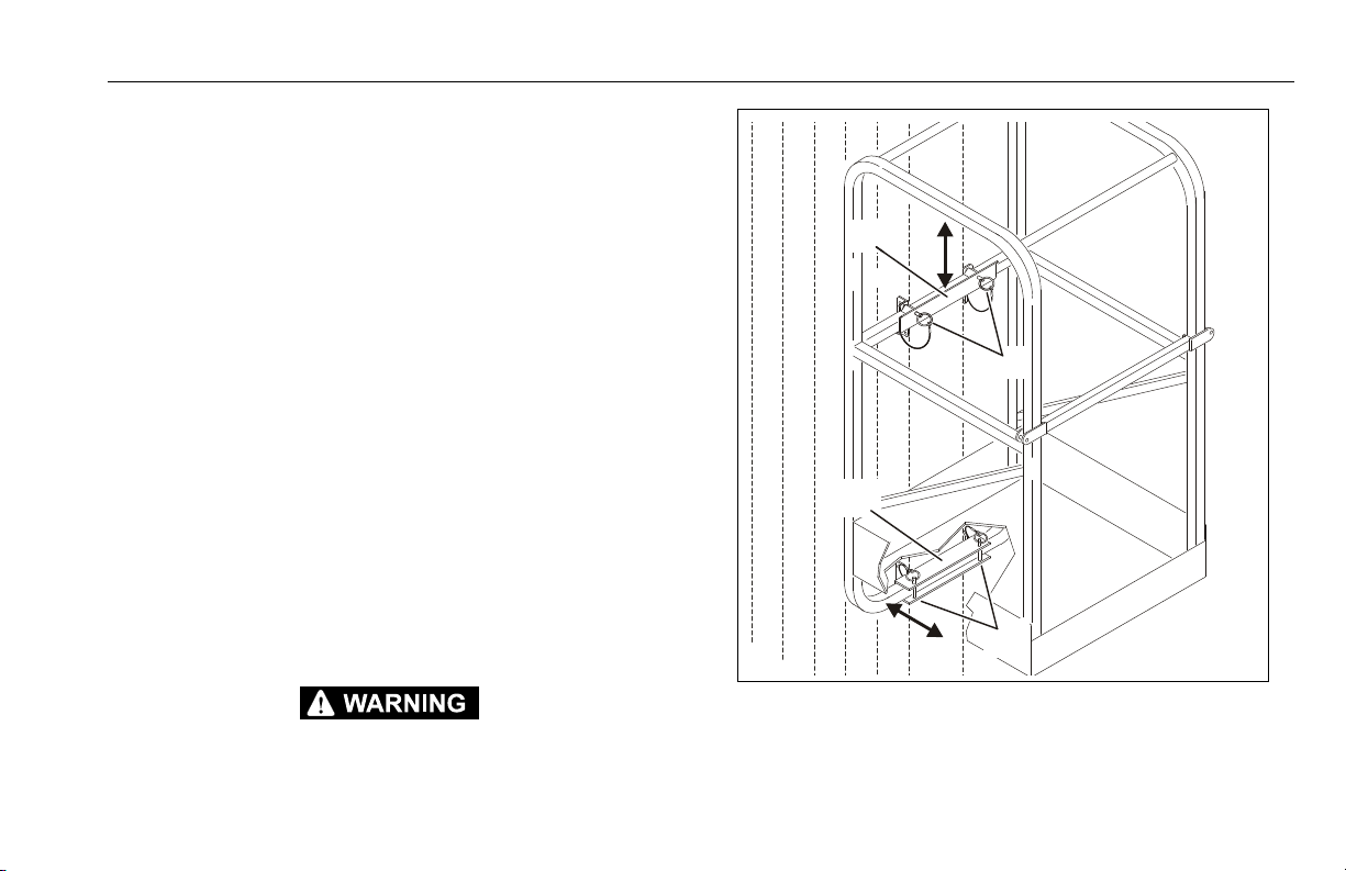
STOCKPICKER PLATFORM
(OPEN RAIL CONFIGURATION) (MSP)
1. Platform Mid-Gate (enter platform behind mid-gate and close
the mid-gate when driving with front rails open).
2. Open Rail Configuration work area. (See Caution on previous
page about fall protection requirements).
3. Platform Control Console attached to fixed side-rail in the rear
of the platform.
3121230 – JLG Lift – 3-29
Page 56

SECTION 3 - MACHINE CONTROLS, INDICATORS AND OPERATION
3.9 FALL PROTECTION - LANYARD ATTACHMENT
JLG INDUSTRIES, INC. RECOMMENDS THE OPERATOR IN THE PLATFORM
WEAR A FULL BODY HARNESS WITH A LANYARD ATTACHED TO AN
AUTHORIZED LANYARD ANCHORAGE POINT.
The lanyard attach point for MVL/MSP machines depends on the
type of platform attached to the machine.
• Quick Change (removable) platforms use a lanyard attach
point located on the lower left side of the mast header, just
behind the platform (see illustration).
• Fixed platforms (bolted permanently to the mast), have lanyard attach points located on the mid or upper platform rail
at the rear of the platform. See specific platform illustration
starting at “PLATFORM CONFIGURATIONS” on page 3-24.
AFTER ENTERING THE PLATFORM, BEFORE BEGINNING OPERATION
ALWAYS CLOSE THE PLATFORM ENTRY GATE(S).
3-30 – JLG Lift – 3121230
Page 57
SECTION 3 - MACHINE CONTROLS, INDICATORS AND OPERATION
1
3
2
4
3.10 QUICK-CHANGE PLATFORM MOUNTING
MVL Model Lifts are equipped with quick-change platform mounts
which allow quick removal and installation of currently available
quick-change platforms.
NOTE: MSP Models require the installation of the Quick-Change
mount kit to use Quick-Change Platforms.
Platform Removal (see illustration following)
1. Remove the platform control console from the platform and
lay aside.
2. Remove both upper and lower mount attach pins securing
the platform support rails to the mast mounting channels.
3. Swing and lift the platform out of the mounts and lay aside.
Platform Installation
1. Set platform in upper and lower mounts.
2. Install attach pins in upper and lower mounts.
3. Attach platform control console to platform rail.
ENSURE ALL PINS AND FASTENERS ARE INSTALLED AND SECURE
PRIOR TO OPERATION.
3121230 – JLG Lift – 3-31
Quick-Change Platform Mounting
1. Upper Platform Mount 3. Lower Platform Mount
2. Upper Mount Attach Pins 4. Lower Mount Pins
Page 58

SECTION 3 - MACHINE CONTROLS, INDICATORS AND OPERATION
3.11 TRANSPORTING, LIFTING AND TIE DOWN PROCEDURES
General
All MVL and MSP Model Personnel Lifts may be transported to a
work site using the following methods:
• Driving the machine around on its base wheels if travel surface area permits.
• Loaded, IN AN UPRIGHT POSITION ONLY onto a heavy-duty
vehicle with the payload capacity capable of supporting the
full weight of the machine (Check machine gross weights in
the Operating Spec Chart at the beginning of this Section).
• Moved with a fork-lift truck using the fork-lift pockets in the
base frame.
Truc k Tra nsp ort
DO NOT TRANSPORT THE MACHINE IN A HORIZONTAL POSITION DUE TO
LEAKAGE OF BATTERY ACID FROM THE BATTERIES OR HYDRAULIC FLUID
FROM THE HYDRAULIC RESERVOIR.
The machine may be winched onto a tilted roll-back truck bed
(see important note following) which has been rolled back to
ground level. Disengage the brakes and always winch (pull) from
the mast (rear) end of the machine, using the rear tie-down loop
attached to the base frame.
DO NOT ATTEMPT TO DRIVE MACHINE ONTO, OFF OF, OR PUSH MACHINE
ONTO A TILTED ROLL-BACK TRUCK BED.
THE MVL AND MSP MACHINES POWER MODULE COULD SUSTAIN SERIOUS DAMAGE WHEN THE UNIT IS PUSHED, OR TOWED AT SPEEDS
GREATER THAN 2 MPH.
WHEN TOWING OR WINCHING, THE MACHINE’S BRAKES MUST BE DISENGAGED.
RE-ENGAGE THE BRAKES ONCE MACHINE IS IN PLACE WITH TRUCK BED
LEVEL AND READY FOR TIE DOWN.
TIE DOWN LOOPS ARE PROVIDED ON BOTH ENDS OF THE BASE FRAME TO
SECURE MACHINE TO BED OF TRANSPORT VEHICLE.
3-32 – JLG Lift – 3121230
Page 59

SECTION 3 - MACHINE CONTROLS, INDICATORS AND OPERATION
1
2
Machine Tie-Down
With machine in position to be tied down and brakes engaged,
use the following guidelines for restraining the machine during
transport.
USE OF EXCESSIVE FORCE WHEN SECURING MACHINE (DRIVE WHEEL
LOAD), CAN CAUSE DAMAGE TO THE MACHINES DRIVE WHEEL COMPONENTS.
1. Secure machine with an adequate chain attached through
the tie down loops located at the front and rear of machine.
(See Figure 3-6.)
2. The chain should be securely tightened with a force of
approximately 100 lb. applied two feet from the pivot handle.
Crane Hook Accessory (Option)
The crane hook accessory provides an attachment point for a lifting device to lift the machine. The lifting device must be capable of
handling the gross weight of the machine, see the machine specifications Section 5 of this manual.
DO NOT ATTEMPT TO USE THE CRANE HOOK ACCESSORY AS AN ATTACH
POINT TO LIFT ITEMS WITH THE MAST ASSEMBLY. THIS WILL RESULT IN
DAMAGE TO THE MAST AND POSSIBLE MACHINE TIPPING.
Figure 3-5. Crane Hook Accessory
1. Crane Hook Attachment 2. Back of Mast
3121230 – JLG Lift – 3-33
Page 60

SECTION 3 - MACHINE CONTROLS, INDICATORS AND OPERATION
Fork-Lift Truck Transport
All MVL and MSP Model Lifts are equipped with wide fork-lift pockets running the length of the base frame and also through the
sides of the base. (See Figure 3-6.) This allows the machine to be
either transported around a work area or lifted onto a higher level
using a standard fork-lift truck.
NOTE: Fork-lift trucks must be capable of handling the gross
weight of the machine, see Section 5, GENERAL SPECIFICATIONS AND OPERATOR MAINTENANCE of this manual
for machine specifications.
3-34 – JLG Lift – 3121230
Page 61

SECTION 3 - MACHINE CONTROLS, INDICATORS AND OPERATION
Figure 3-6. Forklift Truck Lifting Pockets and Machine Tie Down Loop Locations.
1. Rear Tie-Down Loop
2. Side Fork Lift Pockets
3. No Rear Fork Lifting Decal
4. Front Tie-Down Loop
5. Front Fork Lif t Pockets
3121230 – JLG Lift – 3-35
Page 62

SECTION 3 - MACHINE CONTROLS, INDICATORS AND OPERATION
PSL
™
123
456
789
0
4
5
1
2
3
6
3.12 PROGAMMABLE SECURITY LOCK (PSL™) (MVL/MSP - OPTION)
The optional Programmable Security Lock switch can be programmed with a four (4) digit operators code to allow only those
persons with the code to power-up and operate the machine.
PSL™ Box and Ground Control Locations
Figure 3-7. PSL™ Switch & Ground Control Station
3-36 – JLG Lift – 3121230
Note: (a) Machines with bolt on (fixed) covers, the PSL
Locations - At Rear of Machine.
1. PSL Switch (Inside Right Cover) (a)
2. Ground Control Station
Switch is mounted on outside of right cover.
Figure 3-8. PSL™ Switch Controls & Indicators.
1. ON (Green LED) 4. Key Pad
2. ACCEPT (Amber LED) 5. OFF Switch
3. PROGRAM (Red LED) 6. ON Switch
Page 63

SECTION 3 - MACHINE CONTROLS, INDICATORS AND OPERATION
Machine Power Up using the PSL™
NOTE: When entering code on the key pad, a short beep indi-
cates a properly depressed key, a long beep indicates an
error in depressing key. If an error occurs, you must
restart the code entry process again.
1. Enter the four digit code on the PSL key pad. The ACCEPT AMBER LED indicator will be lit if the code is correct.
2. Press the keypad ON button. The ON - GREEN LED indicator
will light and power will be supplied to the Ground Control
Station.
3. At the ground control station, turn the main power selector
switch from OFF to either Platform Control Mode or Ground
Control Mode.
4. The machine will now operate normally.
Machine Power Down
1. At the Ground Control Station set the main power selector
switch to the OFF position.
2. Press the OFF button on the PSL keypad. No LEDs on the
PSL box will be lit.
Changing the Operator’s Code
The PSL Operators Code can be changed by a supervisor should
the need occur. A separate permanent Supervisor’s Code
matched to the serial number of the PSL box is included on a
sheet in the PSL user manual supplied with the machine.
1. Enter the Supervisor’s code on the key pad. The PROGRAM
- RED LED will be lit if correct code is entered.
NOTE: ON or OFF cannot be one of the four digits of the new
Operator’s code.
2. Enter a new four (4) digit Operator’s code on the keypad.
The ACCEPT - AMBER LED will light up if the new Operator’s
code is accepted.
3. Press the OFF button on the keypad to activate the new
Operator’s code.
NOTE: The new Operator’s code will remain in the PSL even
when power is removed from the equipment, or until the
Supervisor changes the Operator’s code.
3121230 – JLG Lift – 3-37
Page 64

SECTION 3 - MACHINE CONTROLS, INDICATORS AND OPERATION
3.13 OBSTRUCTION SENSING SYSTEM (MSP OPTION)
System Description
The Obstruction Sensing System (OSS) is designed to detect the
presence of obstructions within a predetermined detection zone
beneath the platform, when lowering the platform from an elevated
position.
NOTE: The OSS only operates normally when the Ground Control
Module - Power Selector Switch is set to PLATFORM
CONTROL MODE.
When the Power Selector Switch is set to GROUND CONTROL MODE the OSS will detect an obstruction but will
not stop platform downward movement or sound the
horn. However, the OSS Control Module LED will flash if a
sensor detects the presence of an object.
Operation
NOTE: See Figure 3-10. for the location of the OSS Electronic
module.
When the machine is powered on a RED LED located on the OSS
electronics module will illuminate. During platform lowering, if no
obstructions have entered the detection zone beneath the platform, the platform will lower normally.
If an obstruction is detected within the detection zone beneath the
platform, the platform will;
•Stop Lowering
• The RED LED on the electronics module will flash
• The horn will sound three short blasts
If an obstruction is detected, have the obstruction cleared by
someone on the ground or carefully drive the lift until clear of the
obstruction. Reset the OSS by pressing the horn button on the
platform control once and continue machine operation. Should
the OSS falsely detect an obstruction, the system can be overridden by pressing and holding the horn button while operating the
platform lowering controls.
ALWAYS CHECK THE AREA UNDER THE PLATFORM IS CLEAR OF
OBSTRUCTIONS BEFORE LOWERING THE PLATFORM.
3-38 – JLG Lift – 3121230
Page 65
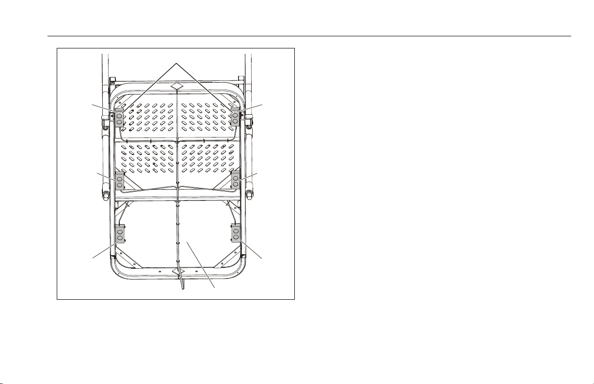
#5
#3
#1
#2
#4
#6
2
1
SECTION 3 - MACHINE CONTROLS, INDICATORS AND OPERATION
OSS Pre-Start Inspection
(See Figure 3-10.)
From ground controls, raise platform approximately 5'-6'. The RED
LED on the electronic module will be illuminated when power is
applied. If an obstruction, such as a pad of paper is placed under
any of the transducer sensor arrays, the RED LED will flash and
remain flashing while the obstruction is present and stop flashing
3 seconds after the obstruction is removed. Check the operation
of each transducer sensor array by placing an object individually
under each sensor array (within approximately 6"-12") and checking if the RED LED starts to "flash", and stops flashing 3 seconds
after the obstruction is removed. Also, inspect the transducer
arrays and electronic module for physical damage, loose wires,
loose mounting hardware, etc.
Figure 3-9. OSS Transducer Sensor Array Location.
1. Transducer Arrays #1 through #6
2. Underside of MSP Platform
3121230 – JLG Lift – 3-39
Page 66

SECTION 3 - MACHINE CONTROLS, INDICATORS AND OPERATION
1
2
3
Pre-Start Inspection
1. Electronic Module LED Indicator (a)
2. Detection Zone
3. Place a pad of paper or similar size object, 6
to 12 in. (15 to 30cm) individually beneath
each transducer to check detection.
NOTE: (a) The LED Indicator will flash when an
object is detected at each sensor. Remove
object and allow the LED to stop flashing
before testing next sensor.
Figure 3-10. OSS - Pre-Start Inspection of Operation.
3-40 – JLG Lift – 3121230
Page 67

SECTION 3 - MACHINE CONTROLS, INDICATORS AND OPERATION
3.14 RUG CARRIER ACCESSORY (MSP - OPTION)
NOTE: The Rug Carrier accessory is available only on the JLG
MSP model and is not authorized for use with any other
JLG lift. The Rug Carrier Accessory is intended for use in
hanging and removal of rugs in hanging display racks
only. Use for any other purpose is not authorized by JLG.
General
The Rug Carrier Accessory consists of two pivoting arms mounted
to the MSP platform left side rails. The pivoting arms are locked in
the plane of the platform side rail when not in use (the stowed
position). The arms are locked into position at approximately 90
degrees to the left side platform side rails when in use (the carry
position). The pivoting arms’ position can be changed by lifting
each arm to release the lock, rotating the arm, and lowering each
arm back into a locked position.
Pre-Start Inspection
Prior to use of the Rug Carrier accessory, check the following;
• Carrier arm mounting is secure to the platform railing, no
missing or damaged fasteners.
• The arm lock pins are in place and working properly.
Hanging a Rug using the Rug Carrier Accessory Arms
The following is a description for use of the Rug Carrier accessory
in hanging rugs on horizontal pivoting arm display racks.
1. Select the intended location in the display for mounting the
rug. Open the display rack to provide adequate space for
the MSP lift and rug.
2. With the Rug Carrier Accessory arms stowed, drive the MSP
into position prior to loading the rug.
3. Swing and lock Rug Carrier Accessory arms into the carry
position.
4. Load the rolled rug with the finished side facing the platform.
As required, use an assistant to load the rug onto the Rug
Carrier Accessory arms.
5. Make sure that the rug is centered over its length on the Rug
Carrier Accessory.
6. Elevate the platform to the required height for mounting the
rug onto the display arm.
7. Properly attach the rug to the display arm. Never climb onto
the platform rails for any reason.
8. After adequately attaching the rug to the display arm, lower
the platform, stow the Rug Carrier Accessory arms.
3121230 – JLG Lift – 3-41
Page 68
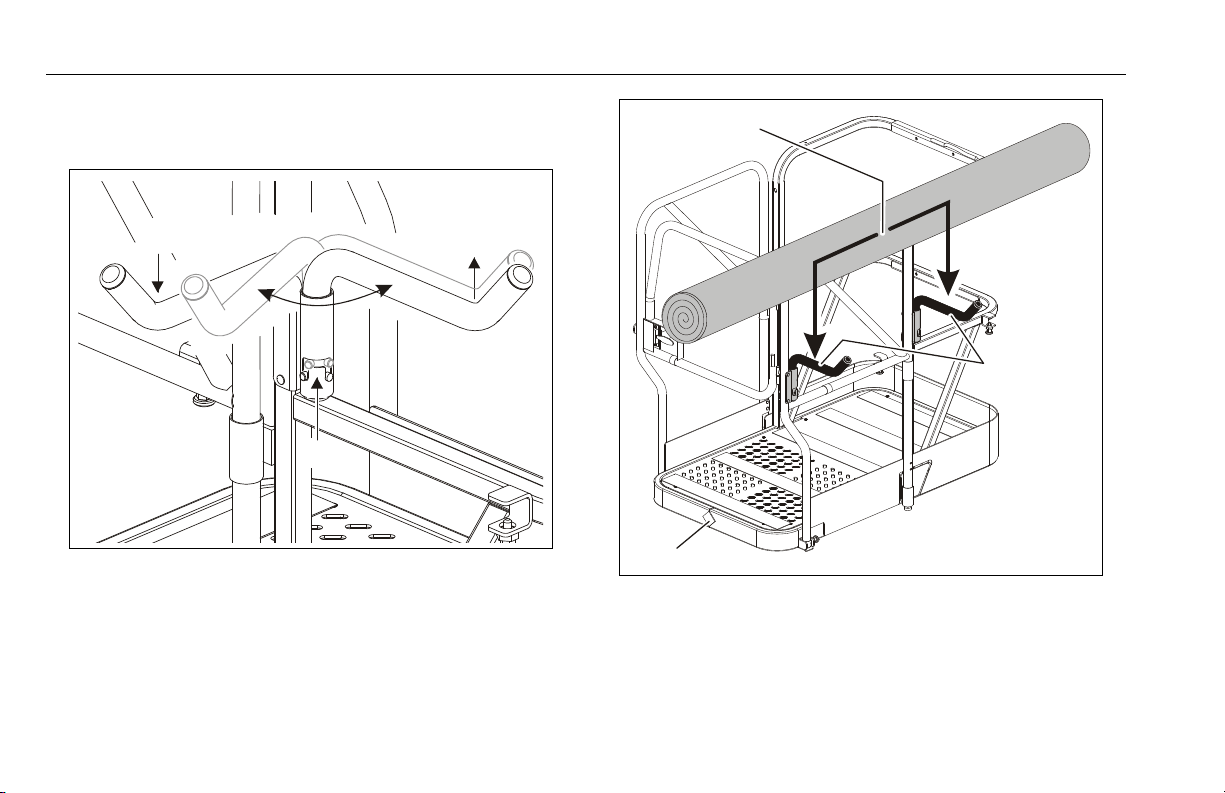
SECTION 3 - MACHINE CONTROLS, INDICATORS AND OPERATION
3
2
1
2
1
3
9. As required reposition and elevate the MSP to completely
attach the rug.
Positioning Rug Carrier Arms
1. Carry Position 3. Lift Arm Up, Swing
2. Stowed Position and Lock into Position
Note: (a) Maximum Capacity of Arms - 150 lb. (68kg)
Positioning Carpet Roll On Rug Carrier
1. Center Carpet on Arms 3. Platform Front
2. Rest on Arms Here (a)
3-42 – JLG Lift – 3121230
Page 69
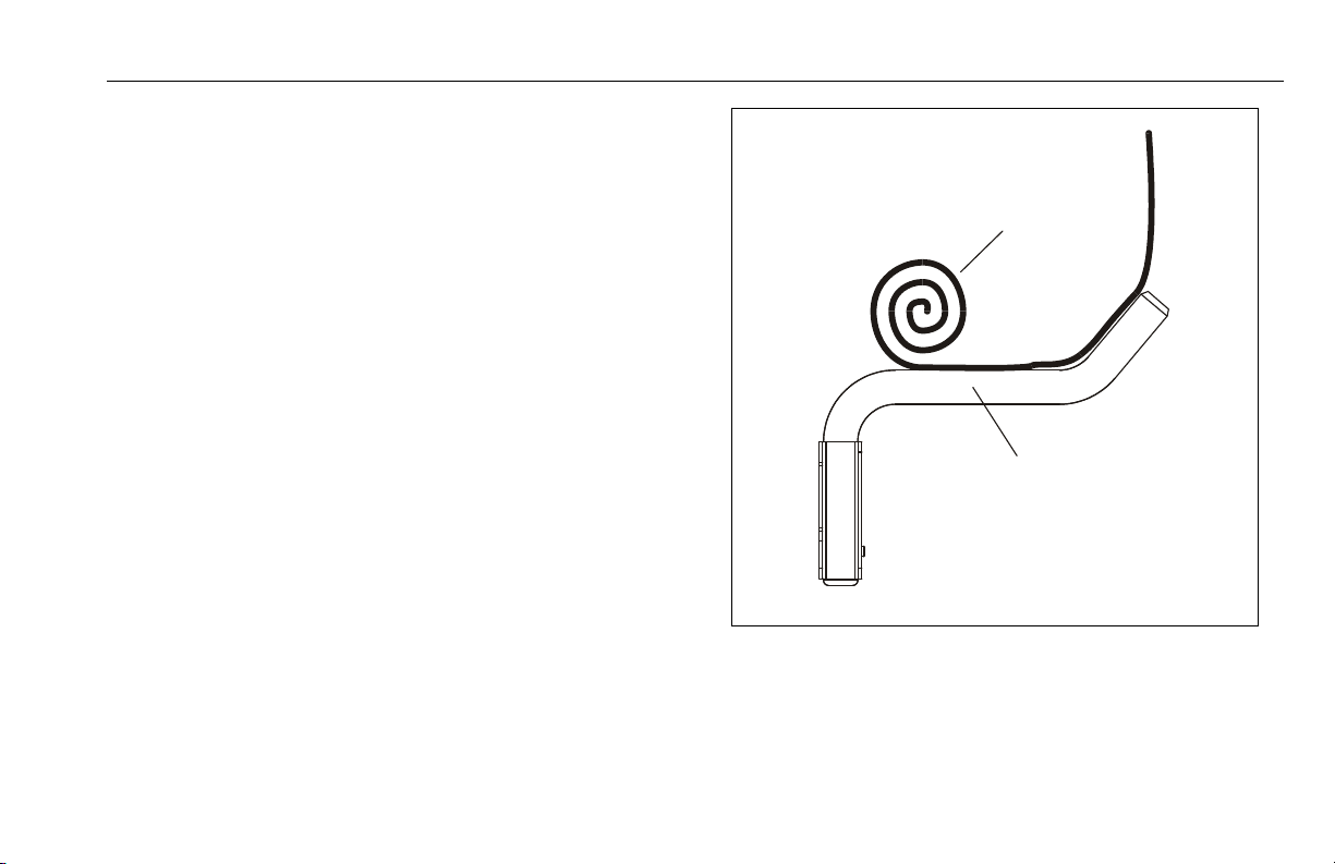
SECTION 3 - MACHINE CONTROLS, INDICATORS AND OPERATION
1
2
Removing a Rug using Rug Carrier Accessory Arms
This section describes the use of the Rug Carrier accessory in
removing a rug from a horizontal pivoting arm display rack.
1. Select the intended location in the display for removal of the
rug. Open the display rack to provide adequate space for
the MSP lift and rug.
2. With the Rug Carrier Accessory arms stowed, drive the MSP
into position prior to loading the rug.
3. Swing and lock the Rug Carrier Accessory arms into the
carry position.
4. Elevate the platform a few feet. Start to roll the rug onto the
Rug Carrier Accessory arms.
5. Be certain the rug is centered over its length on the Rug Carrier Accessory.
6. While elevating to the required height for removing the rug
from the display arm, continue to roll the rug until it is completely rolled up on the carrier arms.
7. Properly remove the rug from the display arm. Never climb
onto the platform rails for any reason.
8. After adequately removing the rug from the display arm,
lower the platform.
Removing Rug From Display Arm.
1. Roll Rug onto Rug Carrier while Elevating Platform
2. Rug Carrier in Carry Position
3121230 – JLG Lift – 3-43
Page 70

SECTION 3 - MACHINE CONTROLS, INDICATORS AND OPERATION
9. Remove the rug from the Rug Carrier Accessory. If required,
use an assistant to unload the rug from the Rug Carrier
Accessory Arms.
10. Replace the Rug Hanger Accessory arms to the stowed position for normal operation.
THE RUG CARRIER ACCESSORY ARMS MUST BE LOCKED IN THE STOWED
POSITION WHEN NOT IN USE.
EXTREME CAUTION MUST BE EXERCISED AT ALL TIMES WHILE THE RUG
CARRIER ACCESSORY IS IN USE (DRIVING, RAISING AND LOWERING) TO
PREVENT OBSTACLES AND PERSONNEL FROM STRIKING THE LOAD.
WHEN DRIVING WITH A RUG WITHIN THE RUG CARRIER ACCESSORY, THE
RUG MUST BE PROPERLY SECURED TO PREVENT INADVERTENT MOTION
OR MOVEMENT OF THE RUG AND MUST NOT EXCEED THE RATED CAPACITY OF THE RUG CARRIER ACCESSORY.
NEVER OVERLOAD THE RUG CARRIER ACCESSORY. MAXIMUM CAPACITY
OF THE RUG CARRIER ACCESSORY IS 150 LBS.
THE COMBINED WEIGHT OF PERSONNEL, MATERIALS, EQUIPMENT PLUS
ANY LOAD ON THE RUG CARRIER ACCESSORY MUST NOT EXCEED THE
MAXIMUM CAPACITY OF THE PLATFORM.
MOUNTINGS. IMMEDIATELY REPORT ANY DAMAGE TO APPROPRIATE
PERSONNEL. DISCONTINUE USE OF THE RUG CARRIER ACCESSORY
UNTIL ALL DISCREPANCIES HAVE BEEN CORRECTED.
NEVER USE A RUG CARRIER ACCESSORY THAT HAS DAMAGE OR LOOSE
3-44 – JLG Lift – 3121230
Page 71

SECTION 3 - MACHINE CONTROLS, INDICATORS AND OPERATION
3.15 STOCK-PICKER HANGER ACCESSORY
NOTE: The stock-picker hanger accessory is available only on
the JLG MSP model and is not authorized for use with any
other JLG lift. This hanger accessory is intended for use
in placing or retrieving stock items such as bicycles, ladders, etc., on racks or shelves above ground level. Use
for any other purpose is not authorized by JLG.
The hanger accessory is a pivoting arm mounted to the MSP platform rail. The hanger accessory can be mounted to either side of
the platform individually, or two can be mounted, one on each side
of the platform. Each individual hanger has a maximum load
capacity of 100 lb. (45kg).
The hanger arm can be pivoted out of the way parallel with the
platform side rails when not in use, (the stowed position). The
hanger arm is pinned into position at 90 degrees to the platform
side rails when in use, (the carry position).
Pre-Start Inspection
Prior to use of the hanger accessory, check the following;
• Hanger arm mounting is secure to the platform railing, no
missing or damaged fasteners.
• The hanger arm lock pin is in place and secure.
THE COMBINED WEIGHT OF PERSONNEL, MATERIALS, EQUIPMENT PLUS
ANY LOAD ON THE HANGER ARM ACCESSORY MUST NOT EXCEED THE
MAXIMUM LOAD CAPACITY OF THE PLATFORM.
Loading and Transporting an Item using the Hanger Accessory
Use the following steps as a guide when loading and transporting
an object with the hanger accessory arm.
1. Keep the hanger arm in the stowed position when not in use.
2. When ready to use, pull the lock pin from the stowed position
hole and swing the hanger arm into the carry position. Place
pin in the carry position hole locking the hanger arm in place.
3. Load the object onto the hanger arm and use the hanger arm
strap to secure the object during transport.
MSP MACHINE’S EQUIPPED WITH THE OBSTRUCTION SENSING SYSTEM
(OSS) OPTION – OBJECTS PLACED ON THE HANGER ACCESSORY AND
EXTENDING BELOW THE BASE OF THE PLATFORM MAY CAUSE AN OSS
DETECTION - SOUNDING THE HORN AND PREVENTING THE PLATFORM
FROM LOWERING. IF NECESSARY, REPOSITION THE OBJECT OUT OF THE
OSS DETECTION ZONE.
3121230 – JLG Lift – 3-45
Page 72

SECTION 3 - MACHINE CONTROLS, INDICATORS AND OPERATION
1
2
4
3
5
1
2
3
4. Be aware of clearance above, below, and around the object
when driving and lifting or lowering the platform.
Stock Picker Hanger - Carry Position
1. Mounting Bracket 4. Lock Pin (Carry Position)
2. Hanger Arm (Carry Position) 5. Hanger Arm Strap
3. Capacity Decal (a)
Notes: (a) Maximum load capacity of hanger is 100 lb. (45kg).
3-46 – JLG Lift – 3121230
1. Hanger Arm (Stowed Position)3. Hanger Arm (Carry Position)
2. Lock Pin (Stowed Position)
Stock Picker Hanger - Stowed Position
Page 73
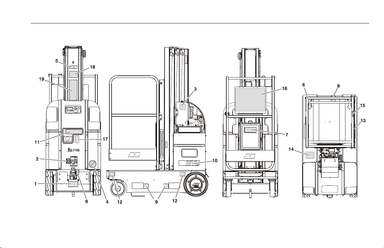
SECTION 3 - MACHINE CONTROLS, INDICATORS AND OPERATION
Figure 3-11. MVL Series Decal Installation Chart - (See Table 3-4 for Installation)
3121230 – JLG Lift – 3-47
Page 74

SECTION 3 - MACHINE CONTROLS, INDICATORS AND OPERATION
Table 3-4. MVL Series Decal Installation Chart.
ANSI
1
1705016 1705016 1705016 — 1705016 1705016 1705016 1705016 1705016 1705016 1705016 1705016 1705016
2
1701504 1701504 1701504 — 1701504 1701504 1701504 1701504 1701504 1701504 1701504 1701504 1701504
3
1702631 1702631 1702631 — 1702631 1702631 1702631 1702631 1702631 1702631 1702631 1702631 1702631
4
1703072 1703072 1703072 — 1703072 1703072 1703072 1703072 1703072 1703072 1703072 1703072 1703072
5
1703681 1703681 1703681 — 1703681 1703681 1703681 1703681 1703681 1703681 1703681 1703681 1703681
6
1703687 1703687 1703687 — 1703687 1703687 1703687 1703687 1703687 1703687 1703687 1703687 1703687
7
1701509 1701509 1701509 — 1701509 1701509 1701509 1701509 1701509 1701509 1701509 1701509 1701509
8
1703814 1703814 1703814 — 1703814 1703814 1703814 1703814 1703814 1703814 1703814 1703814 1703814
9
1703817 1703817 1703817 — 1703817 1703817 1703817 1703817 1703817 1703817 1703817 1703817 1703817
15MVL -
1706744
10
20MVL -
1706746
11
1705834 1705834 1705834 — 1705834 1705834 1705834 1705834 1705834 1705834 1705834 1705834 1705834
12
1705059 1705059 1705059 — 1705059 1705059 1705059 1705059 1705059 1705059 1705059 1705059 1705059
13
1703786 1704032 1704024 — 1704081 1001162896 1705099 1705099 1705099 1705099 1705099 1705099 1705099
14
1700584 1700584 1700584 — 1700584 1700584 1700584 1700584 1700584 1700584 1700584 1700584 1700584
ANSI
(LAT)
15MVL -
1706744
20MVL -
1706746
ANSI
(BRZ)
15MVL -
1706744
20MVL -
1706746
ANSI
(JPN)
— 15MVL -
ANSI
(CHI)
1706744
20MVL -
1706746
CSA
(FRE)
15MVL -
1706744
20MVL -
1706746
CE
(ENG/
(AUS)
15MVL -
1706744
20MVL -
1706746
CE
(GER)CE(FRE)CE(SPA)CE(ITA)CE(DUT)CE(SWE)
15MVL -
1706744
20MVL -
1706746
15MVL -
1706744
20MVL -
1706746
15MVL -
1706744
20MVL -
1706746
15MVL -
1706744
20MVL -
1706746
15MVL -
1706744
20MVL -
1706746
15MVL -
1706744
20MVL -
1706746
3-48 – JLG Lift – 3121230
Page 75

SECTION 3 - MACHINE CONTROLS, INDICATORS AND OPERATION
Ta b l e 3 - 4 . M V L S e r i e s Decal Installation Chart.
ANSI
15
1703684 1703685 1703686 — 1703751 1705959 1703684 1703718 1703719 1703685 1703721 1703722 1705100
15MVL -
1001117179
16
20MVL -
1001117185
17
1703785 1704031 1704023 — 1704079 1001162897 1703785 1704071 1704042 1704031 1704063 1704055 1705102
18
1703779— — — — — — ——————
19
3252797 1702797 1702797 — 1702797 1001095340 3252798 3252798 3252798 3252798 3252798 3252798 3252798
ANSI
(LAT)
15MVL -
1001117182
20MVL -
1001117188
ANSI
(BRZ)
15MVL -
1001117183
20MVL -
1001117187
ANSI
(JPN)
— 15MVL -
ANSI
(CHI)
1001117184
20MVL -
1001117189
CSA
(FRE)
15MVL -
1001162888
20MVL -
1001162895
CE
(ENG/
(AUS)
CE
(GER)CE(FRE)CE(SPA)CE(ITA)CE(DUT)CE(SWE)
15MVL -1001117181
20MVL - 1705960
3121230 – JLG Lift – 3-49
Page 76

SECTION 3 - MACHINE CONTROLS, INDICATORS AND OPERATION
Figure 3-12. MSP Decal Installation Chart - (See Table 3-5. for Installation)
3-50 – JLG Lift – 3121230
Page 77

SECTION 3 - MACHINE CONTROLS, INDICATORS AND OPERATION
Table 3-5. MSP Decal Installation Chart.
ANSI
1
1705016 1705016 1705016 — 1705016 1705016 1705016 1705016 1705016 1705016 1705016 1705016 1705016 1705016
2
1701504 1701504 1701504 — 1701504 1701504 1701504 1701504 1701504 1701504 1701504 1701504 1701504 1701504
3
1702631 1702631 1702631 — 1702631 1702631 1702631 1702631 1702631 1702631 1702631 1702631 1702631 1702631
4
1703072 1703072 1703072 — 1703072 1703072 1703072 1703072 1703072 1703072 1703072 1703072 1703072 1703072
5
1703681 1703681 1703681 — 1703681 1703681 1703681 1703681 1703681 1703681 1703681 1703681 1703681 1703681
6
1703687 1703687 1703687 — 1703687 1703687 1703687 1703687 1703687 1703687 1703687 1703687 1703687 1703687
7
1703788 1703788 1703788 — 1703788 1703788 1703788 1703788 1703788 1703788 1703788 1703788 1703788 1703788
8
1703814 1703814 1703814 — 1703814 1703814 1703814 1703814 1703814 1703814 1703814 1703814 1703814 1703814
9
1703817 1703817 1703817 — 1703817 1703817 1703817 1703817 1703817 1703817 1703817 1703817 1703817 1703817
15MSP -
1706745
10
20MSP -
1706747
11
1705834 1705958 1705860 — 1705862 1705958 1705958 1705958 1705958 1705958 1705958 1705958 1705958 1705958
12
1705059 1705059 1705059 — 1705059 1705059 1705059 1705059 1705059 1705059 1705059 1705059 1705059 1705059
13
1703786 1704032 1704024 — 1704081 1001162896 1705099 1705099 1705099 1705099 1705099 1705099 1705099 1705099
14
1700584 1700584 1700584 — 1700584 1700584 1700584 1700584 1700584 1700584 1700584 1700584 1700584 1700584
ANSI
(LAT)
15MSP -
1706745
20MSP -
1706747
ANSI
(BRZ)
15MSP -
1706745
20MSP -
1706747
ANSI
(JPN)
— 15MSP -
ANSI
(CHI)
1706745
20MSP -
1706747
CSA
(FRE)
15MSP -
1706745
20MSP -
1706747
CE
(ENG/
(AUS)
15MSP -
1706745
20MSP -
1706747
CE
(GER)CE(FRE)CE(SPA)CE(ITA)CE(DUT)CE(SWE)CE(FIN)
15MSP -
1706745
20MSP -
1706747
15MSP -
1706745
20MSP -
1706747
15MSP -
1706745
20MSP -
1706747
15MSP -
1706745
20MSP -
1706747
15MSP -
1706745
20MSP -
1706747
15MSP -
1706745
20MSP -
1706747
15MSP -
1706745
20MSP -
1706747
3121230 – JLG Lift – 3-51
Page 78

SECTION 3 - MACHINE CONTROLS, INDICATORS AND OPERATION
Table 3-5. MSP Decal Installation Chart.
ANSI
15
1703684 1703685 1703686 — 1703751 1705959 1703684 1703718 1703719 1703685 1703721 1703722 1705101 1705100
15MVL -
1001117179
16
20MVL -
1001117185
17
1703785 1704031 1704023 — 1704079 1001162897 1703785 1704071 1704042 1704031 1704063 1704055 1705103 1705102
18
1703779 — — — — — ————————
19
3252797 3252797 3252797 — 3252797 1001095340 3252798 3252798 3252798 3252798 3252798 3252798 3252798 3252798
20
4420051 4420051 4420051 — 4420051 4420051 4420051 4420051 4420051 4420051 4420051 4420051 4420051 4420051
21
— — — — — 1705966 1705966 1705966 1705966 1705966 1705966 1705966 1705966 1705966
22
1704366 1705141 1705142 — 1704910 1704804 1705965 1705965 1705965 1705965 1705965 1705965 1705965 1705965
23
1704469 1705153 1705154 — 1705155 1705156 1705964 1705964 1705964 1705964 1705964 1705964 1705964 1705964
ANSI
(LAT)
15MVL -
1001117182
20MVL -
1001117188
ANSI
(BRZ)
15MVL -
1001117183
20MVL -
1001117187
ANSI
(JPN)
— 15MVL -
ANSI
(CHI)
1001117184
20MVL -
1001117189
CSA
(FRE)
15MVL -
1001162888
20MVL -
1001162895
CE
(ENG/
(AUS)
CE
(GER)CE(FRE)CE(SPA)CE(ITA)CE(DUT)CE(SWE)CE(FIN)
15MVL -1001117181
20MVL - 1705960
3-52 – JLG Lift – 3121230
Page 79

SECTION 4 - EMERGENCY PROCEDURES
SECTION 4. EMERGENCY PROCEDURES
4.1 GENERAL INFORMATION
This section explains the steps to be taken in case of an emergency situation during operation.
4.2 EMERGENCY OPERATION
Operator Unable to Control Machine
IF THE PLATFORM OPERATOR IS PINNED, TRAPPED OR
UNABLE TO OPERATE OR CONTROL THE MACHINE:
1. Other personnel should operate the machine from
ground controls only as required.
2. Only qualified personnel in the platform may use the
platform controls. DO NOT CONTINUE OPERATION IF
CONTROLS DO NOT FUNCTION PROPERLY.
3. Rescue equipment can be used to remove the platform
occupant. Cranes and forklifts can be used to stabilize
motion of the machine.
Platform Caught Overhead
If the platform becomes jammed or snagged in overhead structures or equipment, rescue the platform occupant prior to freeing
the machine.
4.3 INCIDENT NOTIFICATION
JLG Industries, Inc. must be notified immediately of any incident
involving a JLG product. Even if no injury or property damage is
evident, the factory should be contacted by telephone and provided with all necessary details.
USA: 877-JLG-SAFE (554-7233)
Outside USA: 717-485-5161
E-mail: productsafety@jlg.com
Failure to notify the manufacturer of an incident involving a JLG
Industries product within 48 hours of such an occurrence may
void any warranty consideration on that particular machine.
FOLLOWING ANY ACCIDENT, THOROUGHLY INSPECT THE MACHINE
AND TEST ALL FUNCTIONS FIRST FROM THE GROUND CONTROL STATION, THEN FROM THE PLATFORM CONTROL CONSOLE. DO NOT ELEVATE PLATFORM UNTIL YOU ARE SURE THAT ALL DAMAGE HAS BEEN
REPAIRED, IF REQUIRED, AND THAT ALL CONTROLS ARE OPERATING
CORRECTLY.
3121230 – JLG Lift – 4-1
Page 80

SECTION 4 - EMERGENCY PROCEDURES
NOTES:
4-2 – JLG Lift – 3121230
Page 81

SECTION 5 - GENERAL SPECIFICATIONS AND OPERATOR MAINTENANCE
SECTION 5. GENERAL SPECIFICATIONS AND OPERATOR MAINTENANCE
5.1 INTRODUCTION
This section of the manual provides additional necessary information to the operator for proper operation and maintenance of
this machine.
The maintenance portion of this section is intended as information to assist the machine operator to perform daily maintenance tasks only, and does not replace the more thorough
Preventive Maintenance and Inspection Schedule included in
the Service and Maintenance Manual.
Other Publications Available Specific to this Machine:
Service and Maintenance Manual
GLOBAL.................................................................. 3121231
Illustrated Parts Manual
GLOBAL.................................................................. 3121232
3121230 – JLG Lift – 5-1
Page 82
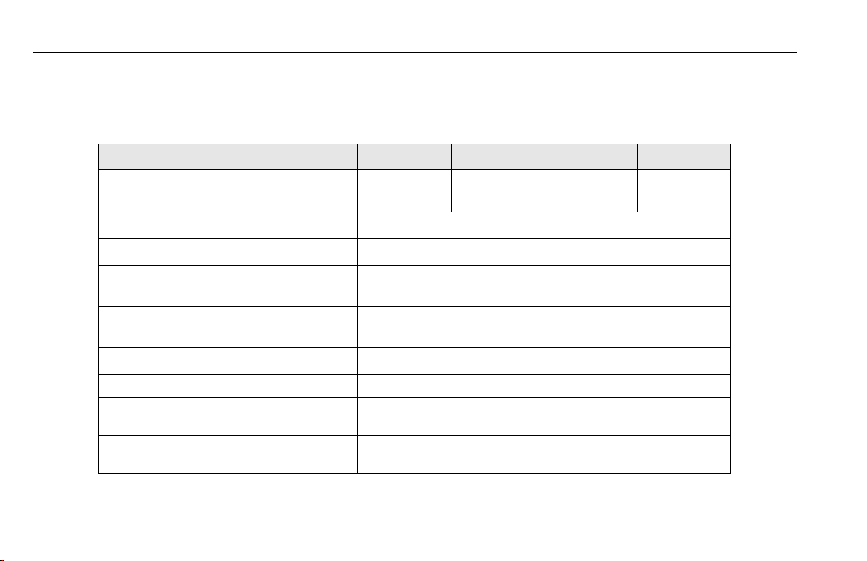
SECTION 5 - GENERAL SPECIFICATIONS AND OPERATOR MAINTENANCE
5.2 GENERAL SPECIFICATIONS
Machine Specifications
SPECIFICATION 15MVL 20MVL 15MSP 20MSP
Gross Machine Weight (Platform Empty):
Machine Height (Platform Stowed):
Tilt Indicator Setting: 1.5°
Maximum Travel Grade (Gradeability):
(Platform STOWED ONLY)
Maximum Travel Grade (Side Slope):
(Platform STOWED ONLY)
Maximum Drive Speeds (Operator Variable): 0.5 - 3.4 mph (0.8 - 5.5 kph)
Machine Base - Overall : (Width x Length) 29.25 in.- W x 52 in.- L (74cm) x (132cm)
Maximum Wind Speed: 28 mph (12.5 m/s) - ANSI/CSA
Maximum Horizontal Manual Side Force:
(Platform fully extended with Maximum load)
2,235 lb.
(1,014 kg)
2,235 lb.
(1,014 kg)
78 in. (198cm)
0 mph (0kph) - CE/AUSTRALIA
45 Pound Force (200 Newtons)
2,280 lb.
(1,034 kg)
20%
5°
2,280 lb.
(1,034 kg)
5-2 – JLG Lift – 3121230
Page 83

SECTION 5 - GENERAL SPECIFICATIONS AND OPERATOR MAINTENANCE
SPECIFICATION 15MVL 20MVL 15MSP 20MSP
Maximum Hydraulic System Pressure:
(Recommended initial setting)
Hydraulic System Capacity: 5 qts. U.S. (4.7 L)
Hydraulic Reservoir Capacity: 1 Gallon (3.78 L)
2600 PSI
(180 Bars)
1800 PSI
(124 Bars)
2600PSI
(180 Bars)
2800 PSI
(193 Bars)
3121230 – JLG Lift – 5-3
Page 84
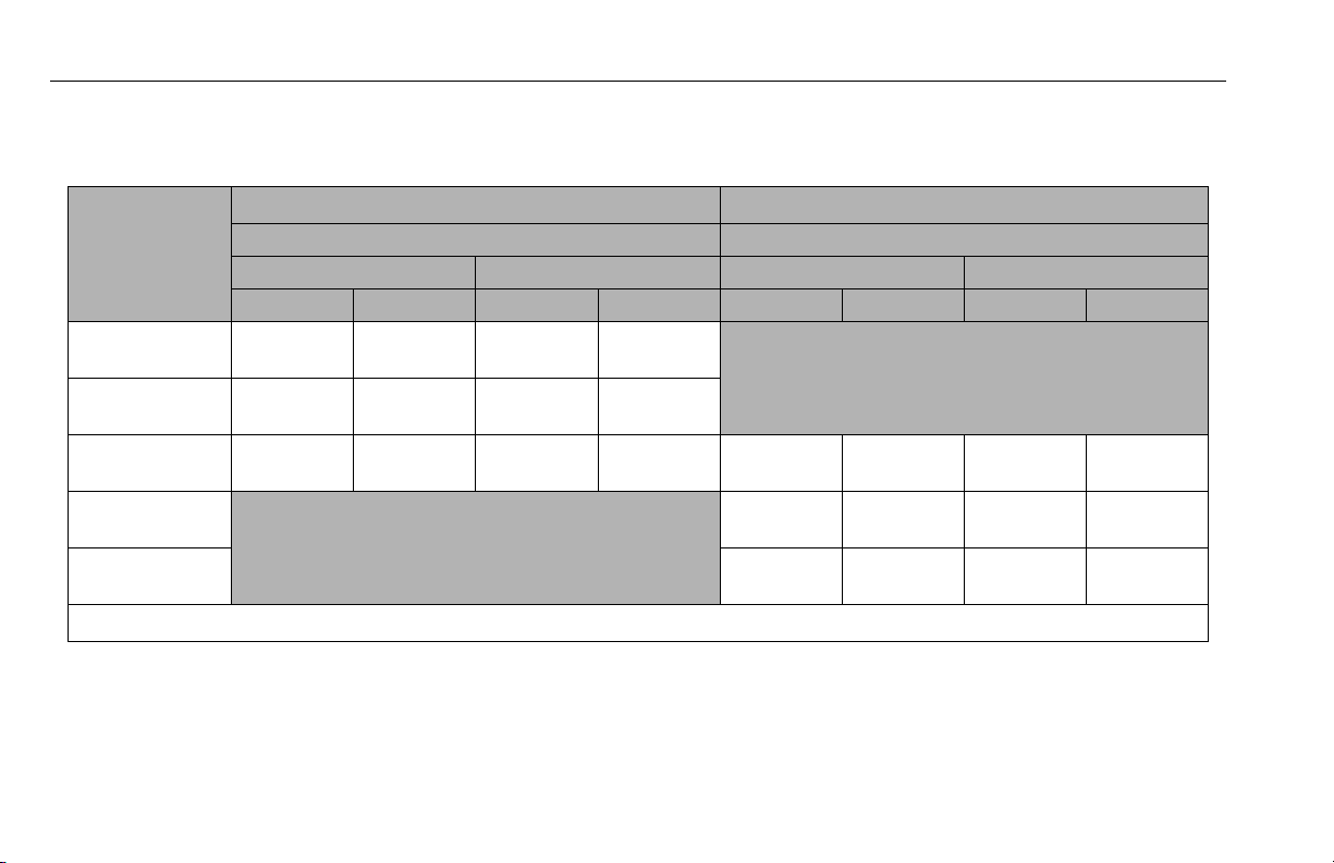
SECTION 5 - GENERAL SPECIFICATIONS AND OPERATOR MAINTENANCE
Machine Wheel Loads and PSI - Per Wheel
Table 5-1. 15MVL/MSP - Machine Maximum Wheel Loads (Lb.) and (PSI) - Per Wheel.
15MVL 15MSP
Platform Type
(Loaded to Max.
Capacity)
Wheel Load Per Wheel (PSI) Per Wheel Wheel Load Per Wheel (PSI) Per Wheel
Average Maximum Average Maximum
Rear Front Rear Front Rear Front Rear Front
22 x 25 SB
28 x 26 GW
26 x 50 GW
28 x 48 SP
w/Folding Tray
865 lb.
(393 kg)
845 lb.
(384 kg)
860 lb.
(390 kg)
490 lb.
(223 kg)
550 lb.
(250 kg)
515 lb.
( 234 kg)
138 PSI
(9.8 kg/cm
128 PSI
(9 kg/cm
115 PSI
(8.0 kg/cm
2
)
2
)
2
)
252 PSI
(17.8 kg/cm2)
265 PSI
(18.7 kg/cm2)
321 PSI
(22.6 kg/cm2)
860 lb.
(390 kg)
755 lb.
(343 kg)
810 lb.
(368 kg)
515 lb.
(234 kg)
615 lb.
(279 kg)
565 lb.
(257 kg)
NOTE: Platform Types: SB - with Sliding Bar Gate GW - with Gull Wing Gate SP - Stock Picker Platform
115 PSI
(8.0 kg/cm2)
117 PSI
(8.3 kg/cm2)
125 PSI
(8.8 kg/cm
(22.6 kg/cm2)
(21.6 kg/cm2)
2
)
(22 kg/cm2)
321 PSI
306 PSI
313 PSI
5-4 – JLG Lift – 3121230
Page 85
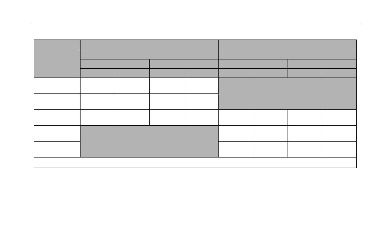
SECTION 5 - GENERAL SPECIFICATIONS AND OPERATOR MAINTENANCE
Table 5-2. 20MVL/MSP - Machine Maximum Wheel Loads (Lb.) and (PSI) - Per Wheel.
20MVL 20MSP
Platform Type
(Loaded to Max.
Capacity)
Wheel Load Per Wheel (Lb.) (PSI) Per Wheel Wheel Load Per Wheel (Lb.) (PSI) Per Wheel
Rear Front Rear Front Rear Front Rear Front
22 x 25 SB
28 x 26 GW
26 x 50 GW
855 lb.
(388 kg)
835 lb.
(379 kg)
850 lb.
(386 kg)
28 x 48 SP
w/Folding Tray
NOTE: Platform Types: SB - with Sliding Bar Gate GW - with Gull Wing Gate SP - Stock Picker Platform
Average Maximum Average Maximum
450 lb.
(206 kg)
460 lb.
(209 kg)
480 lb.
(218 kg)
132 PSI
(9.3 kg/cm
121 PSI
(8.6 kg/cm
131 PSI
(9.3 kg/cm
2
)
(17.6 kg/cm2)
2
)
(18.4 kg/cm2)
2
)
(19.5 kg/cm2)
250 PSI
261 PSI
277 PSI
850 lb.
(386 kg)
815 lb.
(370 kg)
810 lb.
(368 kg)
480 lb.
(218 kg)
560 lb.
(255 kg)
565 lb.
(257 kg)
(9.3 kg/cm2)
(8.5 kg/cm2)
(8.8 kg/cm
131 PSI
120 PSI
125 PSI
(18.3 kg/cm2)
(22.5 kg/cm2)
2
)
(22 kg/cm2)
259 PSI
320 PSI
313 PSI
3121230 – JLG Lift – 5-5
Page 86
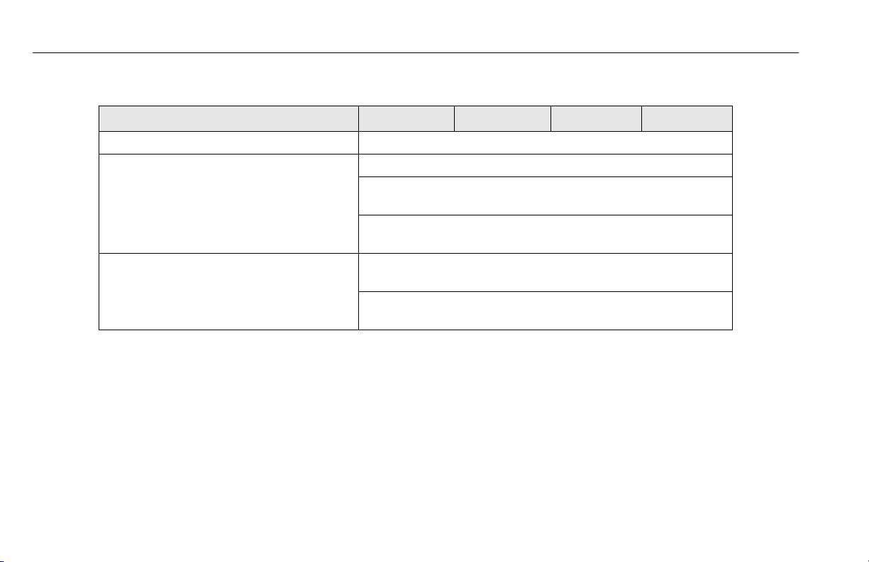
SECTION 5 - GENERAL SPECIFICATIONS AND OPERATOR MAINTENANCE
Electrical Specifications
SPECIFICATION 15MVL 20MVL 15MSP 20MSP
System Voltage: 24 Volts DC
B at t er y S pe c i fi c at i on s : B a tt e r y Ty p e : AGM (VRLA) (Sealed)
Voltage (DC): 12 Volts DC - 2 Battery System
6 Volts DC - 4 Battery System
Amp Hour (AH) Rating: 100 Amp Hr. @ 20 Hr. Rate - 12V - 2 Battery System
220 Amp Hr. @ 20 Hr. Rate - 6V - 4 Batter y System
Battery Charger (DC Models) I n p u t ( A C ) : 120/230 VAC RMS - 45/65 Hz - Voltage Selectable
12AMPS RMS@108 VAC
Output (DC): 24 Volts DC Nominal -33.6 VDC Maximum
25 Amp - Max. DC Output Current
5-6 – JLG Lift – 3121230
Page 87
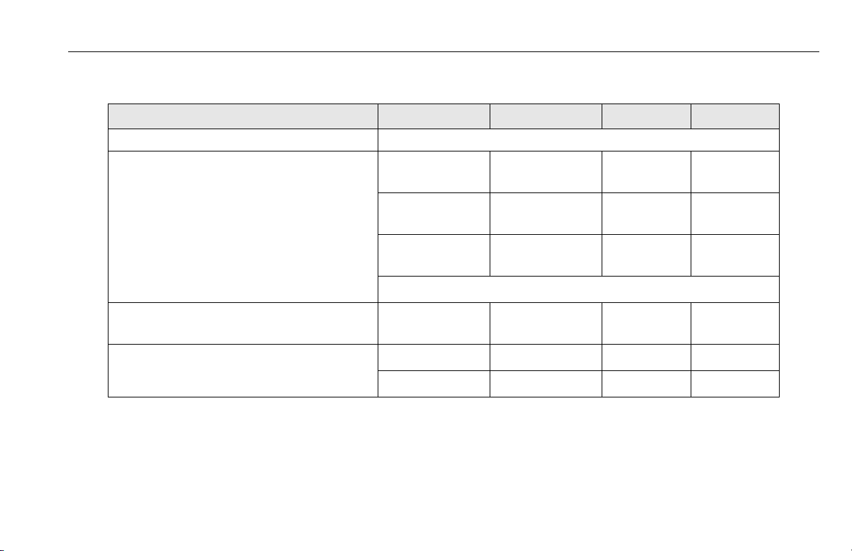
Platform Data
Occupants: (Persons allowed in Platform) 1
M a xi m u m W o r k L o a d ( C a pa c i t y) : G u ll W i n g o r
Platform Height - Mast Fully Extended -
(Ground to Platform Floor):
P l at f o rm C y c le P e rf o r m an c e : L i f t Up :
SECTION 5 - GENERAL SPECIFICATIONS AND OPERATOR MAINTENANCE
SPECIFICATION 15MVL 20MVL 15MSP 20MSP
Front Slide Bar Entry:
Stockpicker:
Extendible:
Platform w/Folding Material Tray:
500 lb.
(230 kg)
——
500 lb.
(230 kg)
15 ft. 2 in.
(4.69 m)
20 sec. 22.5 sec. 20 sec. 22.5 sec.
350 lb.
(160 kg)
500 lb.
(230 kg)
350 lb.
(160 kg)
(See Table 3-3 on page 3-26)
19 ft. 1 in.
(5.80 m)
500 lb.
(230 kg)
15 ft. 1 in.
(4.66 m)
——
400 lb.
(180 kg)
350 lb.
(160 kg)
(1)
19 ft. 6 in .
(5.96 m)
(in seconds) (w/max. rated load) L i f t D o w n :
NOTE: (1) Standard unless equipped with optional 14 ft. Limiter circuit.
15 - 21 sec. 21 - 26 sec. 15 - 21 sec. 21 - 26 sec.
3121230 – JLG Lift – 5-7
Page 88
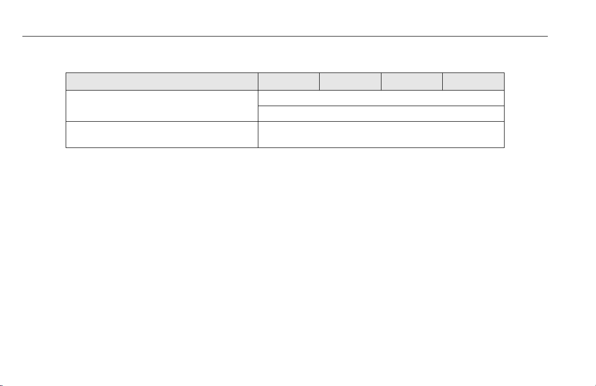
SECTION 5 - GENERAL SPECIFICATIONS AND OPERATOR MAINTENANCE
Machine Component Weights
SPECIFICATION 15MVL 20MVL 15MSP 20MSP
P l a tf o r m W ei g h t : F r on t S l i d e Ba r E n t r y P la t f o r m : 55 lb. (25 kg)
(Quick-Change Platforms) G u l l W i n g P l a t f o r m: 70 lb. (32 kg)
Battery: (per battery) 71-75 lb. (34 kg) - 12 Volt - 2 Battery System
66 lb. (30 kg) - 6 Volt - 4 Battery System
Serial Number Locations
For machine identification, a serial number plate is affixed to the
machine. The plate is located on the back of the mast, just
above the mast support bracket.
5-8 – JLG Lift – 3121230
Page 89

SECTION 5 - GENERAL SPECIFICATIONS AND OPERATOR MAINTENANCE
5.3 OPERATOR MAINTENANCE
Battery
The OEM batteries are AGM sealed (VRLA) type so the electrolyte level cannot be serviced, however the battery terminals
should be checked periodically for corrosion and tightness. The
batteries are located under the top rear hood covers on each
side of the Ground Control Station.
Tires and Wheels
Tire Wear and Damage
Inspect tires periodically for wear or damage. Tires with worn
edges or distorted profiles require replacement. Tires with significant damage in the tread area or side wall, require immediate
evaluation before replacing the machine into service.
Wheel and Tire Replacement
Replacement wheels must have the same diameter and profile
as the original. Replacement tires must be the same size and
rating as the tire being replaced.
Wheel Installation
It is extremely important to apply and maintain proper wheel
mounting torque.
WHEEL LUG NUTS MUST BE INSTALLED AND MAINTAINED AT THE
PROPER TORQUE TO PREVENT LOOSE WHEELS, BROKEN LUG NUTS,
AND POSSIBLE SEPARATION OF WHEEL FROM THE AXLE. BE SURE
TO USE ONLY THE LUG NUTS MATCHED TO THE CONE ANGLE OF THE
WHEEL.
3121230 – JLG Lift – 5-9
Page 90

SECTION 5 - GENERAL SPECIFICATIONS AND OPERATOR MAINTENANCE
Tighten the lug nuts to the proper torque to prevent wheels from
coming loose. Use a torque wrench to tighten the fasteners. If
you do not have a torque wrench, tighten the fasteners with a
lug wrench, then immediately have a service garage or dealer
tighten the lug nuts to the proper torque. Over-tightening will
result in breaking the lug nuts or permanently deforming the
mounting holes in the wheels. The proper procedure for attaching wheels is as follows:
1. Start all lug nuts by hand to prevent cross threading. DO
NOT use a lubricant on threads or nuts.
2. Tighten lug nuts in the following sequence.
Figure 5-1. Wheel Lug Nut Tightening Sequence
3. The tightening of the lug nuts should be done in stages.
Following the recommended sequence, tighten lug nuts
per wheel torque.
Ta b l e 5 - 3 . W h e e l To r q u e C h a r t
TORQUE SEQUENCE
1st Stage 2nd Stage 3rd Stage
20-30 ft lbs
(28 - 42 Nm)
65-80 ft lbs
(91 - 112 Nm)
105 -120 ft lbs
(142 - 163 Nm)
4. Wheel lug nuts should be torqued after the first 50 hours
of operation and after each wheel removal. Check
torque every 3 months or 150 hours of operation.
5-10 – JLG Lift – 3121230
Page 91
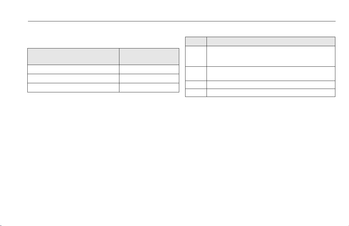
SECTION 5 - GENERAL SPECIFICATIONS AND OPERATOR MAINTENANCE
Lubrication
Hydraulic Oil (HO)
HYDRAULIC SYSTEM OPERATING
TEMPERATURE RANGE
+0° F to +180° F (-18° C to -83° C) 10W
+0° F to +210° F (-18° C to +99° C) 10W-20, 10W-30
+50° F to +210° F (+10° C to +99° C) 20W-20
Hydraulic oils must have anti-wear qualities at least to API Service Classification GL-3, and sufficient chemical stability for
mobile hydraulic system service. JLG Industries, recommends
Mobilfluid 424 hydraulic oil, which has an SAE viscosity of 10W30 and a viscosity index of 152.
For cold weather applications, i.e. when temperatures remain
consistently below +20°F (–7°C) JLG recommends using Mobil
DTE 13 hydraulic oil.
Aside from JLG recommendations, it is not advisable to mix oils
of different brands or types, as they may not contain the same
required additives or be of comparable viscosities. If use of
hydraulic oil other than Mobilfluid 424 is desired, contact JLG
Industries for proper recommendations.
SAE VISCOSITYGRADE
Table 5-4. - Lubrication Specifications
KEY SPECIFICATIONS
MPG - Multipurpose Grease having a minimum dripping point of 350° F.
Excellent water resistance and adhesive qualities, and being of
extreme pressure type. (Timken OK 40 pounds minimum.)
EPGL - Extreme Pressure Gear Lube (oil) meeting API service classification
GL- 5 o r M IL- Sp ec MI L-L- 21 05 .
HO - Hydraulic Oil. ISO-Vg grade 32, 46.
CL - Chain Lube. Use a good quality chain lubricant
NOTE: Refer to Lubrication Chart, Table 5-5 for specific lubrication
locations on machine.
3121230 – JLG Lift – 5-11
Page 92

SECTION 5 - GENERAL SPECIFICATIONS AND OPERATOR MAINTENANCE
Figure 5-2. Location of Lubrication Points (See Table 5-5)
5-12 – JLG Lift – 3121230
Page 93

SECTION 5 - GENERAL SPECIFICATIONS AND OPERATOR MAINTENANCE
ITEM COMPONENT
1Hydraulic Oil
2Mast Chains
Key to Lubricants: MPG - Multipurpose Grease
Notes: (a) Be certain to lubricate like items on each side of the machine.
(b) Recommended lubricating intervals are based on normal use. If machine is subjected to severe operating conditions,
such as a high number of cycles, location, corrosive/dirty environment, etc., user must adjust lubricating requirements accordingly.
(c) P rior to checking hydraulic oil level, operate machine through one complete cycle of lift function (full up and down). Failure to do so
will result in incorrect oil leve l reading on the hydraulic reservoir.
F il l To Li n e o n
Reservoir
5 Qt. Reservoir
2 - Per Mast
S e ct i on
HO - Hydraulic Oil - ISO-Vg grade 32, 46.
CL - Chain Lube. Use a good quality chain lubricant
Table 5-5.Lubrication Intervals for Various Components
NO/TYPE
LUBE POINTS
(a)
LUBE/METHOD
HO - Check Hyd. Oil
L e ve l
HO - Change Hyd. Oil
CL - Brush or Spray
INTERVAL
3
MONTHS6MONTHS1YEAR2YEARS
(b)
✔
✔
COMMENTS
Check fluid level every day.
Change hydraulic oil every 2
years.
Inspect, lubricate if dry or ru sting.
(c)
3121230 – JLG Lift – 5-13
Page 94

SECTION 5 - GENERAL SPECIFICATIONS AND OPERATOR MAINTENANCE
5.4 GROUND CONTROL STATION PROGRAMMING
General
The MVLMSP/MSP machine Ground Control Station allows onboard programming of various component and control function
personality settings.
Programming may be required under circumstances such as:
• Optional equipment has been added to the machine in the
field and a function must be enabled before operation.
• Customizing the machine to fit a specific application, such as
changing the LCD display language.
Programming Levels
There is one (1) password protected programming level available
to the Operator:
• Level-3: Operator’s Settings -
Level-3 Password: 33271
Operator Programming Mode
In the Operator Level Programming Mode the following items are
shown on the main menu (See Table 5-6 for Setting Range and
Default Factory Setting):
• Tilt Sensor
Allows viewing current tilt sensor individual X and Y direction
degree reading.
•Program
Allows programming of the items shown in Table 5-6 on
page 5-16, the following is a brief explanation of each programming item.
NOTE: There are two production modules available at this time,
one for North/South American and European languages,
and one for Asian languages. All programmable items
between these modules are identical with the exception
of language selection.
• Back To Main - When selected, will return to main level
menu.
• Set Language - Selects the language that text on the LCD
screen will be displayed.
• Set Sleep Time - Allows setting the length of time the
machine will remain powered up without control input
before powering itself down.
5-14 – JLG Lift – 3121230
Page 95

SECTION 5 - GENERAL SPECIFICATIONS AND OPERATOR MAINTENANCE
• Set Polarity of Keypad Code - Turns on or off the Programmable Security Lock switch circuit, if equipped.
• Enable Detection of Horn Open Circuit - Enables horn
electrical circuit to be turned on (YES) or off (NO) if
machine is equipped with a horn.
• Enable Detection of Beacon Open Circuit - Enables
mast/base beacon strobe electrical circuits to be turned on
(YES) or off (NO) if machine is equipped with either or both
beacon strobes.
• Forward Alarm Disable - When turned on (YES) will disable the alarm when driving forward.
• OSS Diagnostics - When turned on (YES) will cause the
controller LCD to continuously display the Obstruction
Sensing System (OSS) Diagnostics until turned back off
(NO).......the machine will function normally, but only the
OSS Diagnostics screen will display until this setting is reset to the off (NO) position.
3121230 – JLG Lift – 5-15
Page 96
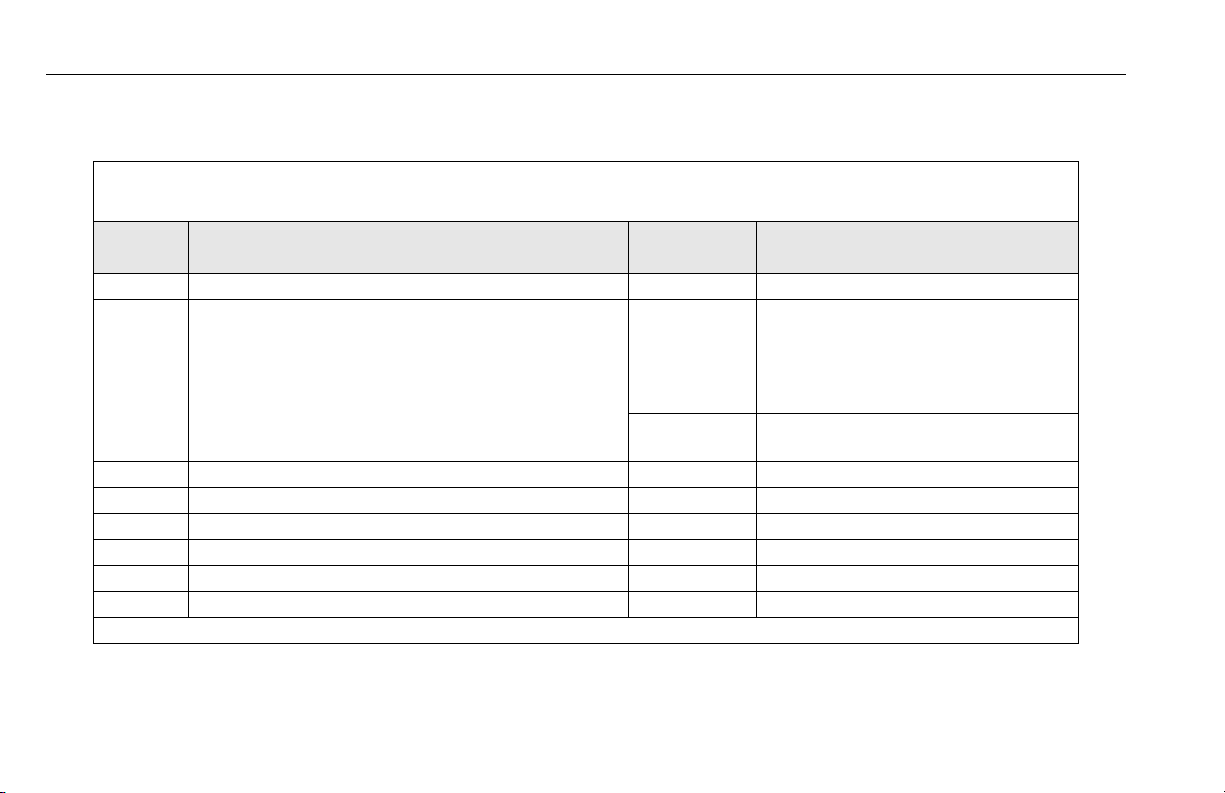
SECTION 5 - GENERAL SPECIFICATIONS AND OPERATOR MAINTENANCE
Table 5-6. Ground Control Module Setting Range and Default Factory Settings.
Level-3: Operator Programmable Settings On LCD Display: YES =
LEVEL PROGRAMMABLE ITEM
3 Back to Main — Return to Main Menu
3 Set Language
NOTE: There are two production modules available
at this time, one for North/South American
and European Languages, and one for
Asian Languages.
3 Set Sleep Time 5 MINS 0 - 60 MINS
3 Set Polarity of the Keypad Code LOW HIGH/LOW
3 Enable Detection of Horn Open Circuit NO (a) YES/NO
3 Enable Detection of Beacon Open Circuit NO (a) YES/NO
3 Forward Alarm Disable NO YES/NO
3 OSS Diagnostics NO YES/NO
Notes:(a) MSP Models this feature is standard equipment and preset to YES at factory.
FACTORY
PRESET
1 1 - English 6 - Italian
2 - German 7 - Swedish
3 - Dutch 8 - Brazilian Portuguese
4 - French 9 - Finnish
5 - Spanish
2 1 - E n gl i sh 3 - Japanese
2 - Chinese
SETTING RANGE
✓ HIGH = ↑
NO = ✕ LO W = ↓
5-16 – JLG Lift – 3121230
Page 97

SECTION 5 - GENERAL SPECIFICATIONS AND OPERATOR MAINTENANCE
1
2
Activating Programming Mode
NOTE: If machine does not power up, check that both the
Ground Control Station - Emergency Stop Button, and the
Platform Control Console - Emergency Stop Button, are in
the RESET position.
Also if machine is equipped with the (PSL) Programmable
Security Lock option, see Section 3.5 of this Operators
Manual for additional machine power-up steps.
1. With machine power OFF, press and hold the Brake
Release Button (1) on the Ground Control Station.
2. While holding the Brake Release Button in, power
machine up by turning the Main Power Selector
Switch (2), to either the Ground Control or Platform
Control Mode.
3. Release the Brake Release Button (1) after machine is
powered up. The LCD display should now display five
zeros, one with a box around. Continue to next step
Entering Password.
3121230 – JLG Lift – 5-17
Page 98

SECTION 5 - GENERAL SPECIFICATIONS AND OPERATOR MAINTENANCE
1
23
00000
4
1
2
3
Entering Password Programming Mode Selection
1. The Brake Release button (1) moves the box from left
to right to select which digit to change.
2. Platform UP button (2) increases the numerical digit.
3. Platform DOWN button (3) decreases the numerical
digit.
4. Change all five digits (4) to match password level, then
press the Brake Release button (1) again.
1. Use Platform UP/DOWN buttons (1) to move the selection box (2) up or down to select item to program.
2. Press the Brake Release button (3) to enter selected
mode then move on to Selecting Programmable Item
to adjust.
5-18 – JLG Lift – 3121230
Page 99
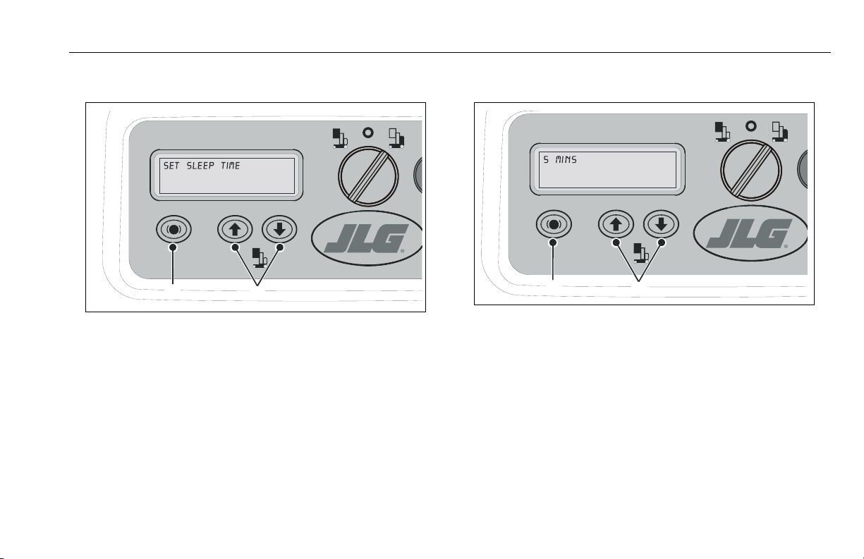
SECTION 5 - GENERAL SPECIFICATIONS AND OPERATOR MAINTENANCE
1
2
1
2
Selecting Programmable Item to Adjust Adjusting Programmable Setting
1. Use the Platform UP/DOWN buttons (1) to scroll
through the list of programmable items available to
your programming level.
2. Once a programmable item to be adjusted is selected,
press the Brake Release button (2) to enter that settings’ adjustment mode.
1. Adjust the programmable setting using the Platform
UP/DOWN buttons (1), see Table 5-6 for range of settings for that item.
2. Once parameter is set for the programmable item,
press the Brake Release button (2), this will enter the
parameter and return you to the Programmable Settings Menu.
TO EXIT Programming Mode after adjusting programmable settings, power machine down with either the Main Power Selector
Switch or Emergency Stop Button.
3121230 – JLG Lift – 5-19
Page 100

SECTION 5 - GENERAL SPECIFICATIONS AND OPERATOR MAINTENANCE
5.5 DRIVE MOTOR BRUSH WEAR - WARNING INDICATION
The machines drive motors include brush wear sensors that
activate a warning indicating the drive motor brushes will require
replacment soon. This warning protects the drive motors from
damage due to extreme brush wear.
When the brush wear warning is activated the Ground Control
Station LCD screen will indicate a fault code of 6, also the hourmeter is set to countdown 25 hours of (DRIVE) operation
remaining.
The Platform Control LEDs will indicate this warning with 8 flashing LEDs and an intermittent beep.
NOTE: Only the drive function when used will affect the hour
meter count down once the warning has been activated.
The machine will operate normally until the last 10 seconds of the 25 hour countdown.
During the last 10 seconds of the 25 hour (DRIVE) countdown
the machine will only drive in creep/turtle drive mode and platform lift up will be disabled. At this point cycling power on/off will
only repeat the final 10 second mode cycle.
The machine will not operate normally until the drive motor
brushes are replaced (repositioning the brush warning sensors),
and the Ground Control Station is programmed to reset the
Brush Wear - Warning Timer per the Service and Maintenance
Manual.
5-20 – JLG Lift – 3121230
 Loading...