

Page 1
Operation and Safety Manual
®
Original Instructions - Keep this manual with the machine at all times.
Boom Lift Models
150HAX
ANSI
3121213
August 30, 2012
Page 2

Page 3

FOREWORD
FOREWORD
This manual is a very important tool! Keep it with the machine at all times.
The purpose of this manual is to provide owners, users, operators, lessors, and lessees with the precautions and
operating procedures essential for the safe and proper machine operation for its intended purpose.
Due to continuous product improvements, JLG Industries, Inc. reserves the right to make specification changes
without prior notification. Contact JLG Industries, Inc. for updated information.
3121213 – JLG Lift – a
Page 4
FOREWORD
SAFETY ALERT SYMBOLS AND SAFETY SIGNAL WORDS
This is the Safety Alert Symbol. It is used to alert you to the potential personal
injury hazards. Obey all safety messages that follow this symbol to avoid possible
injury or death
INDICATES AN IMMINENTLY HAZARDOUS SITUATION. IF NOT
AVOIDED, WILL RESULT IN SERIOUS INJURY OR DEATH. THIS DECAL
WILL HAVE A RED BACKGROUND.
INDICATES A POTENTIALLY HAZARDOUS SITUATION. IF NOT
AVOIDED, COULD
DECAL WILL HAVE AN ORANGE BACKGROUND.
RESULT IN SERIOUS INJURY OR DEATH. THIS
INDICATES A POTENTIALLY HAZARDOUS SITUATION. IF NOT
AVOIDED, MAY RESULT IN MINOR OR MODERATE INJURY. IT MAY
ALSO ALERT AGAINST UNSAFE PRACTICES. THIS DECAL WILL HAVE A
YELLOW BACKGROUND.
INDICATES INFORMATION OR A COMPANY POLICY THAT RELATES
DIRECTLY OR INDIRECTLY TO THE SAFETY OF PERSONNEL OR PROTECTION OF PROPERTY.
b – JLG Lift – 3121213
Page 5

THIS PRODUCT MUST COMPLY WITH ALL SAFETY RELATED BULLETINS. CONTACT JLG INDUSTRIES, INC. OR THE LOCAL AUTHORIZED
JLG REPRESENTATIVE FOR INFORMATION REGARDING SAFETYRELATED BULLETINS WHICH MAY HAVE BEEN ISSUED FOR THIS
PRODUCT.
For:
• Accident Reporting
• Product Safety Publications
• Current Owner Updates
• Questions Regarding
Product Safety
FOREWORD
• Standards and Regulations
Compliance Information
• Questions Regarding Special Product Applications
• Questions Regarding Product Modifications
JLG INDUSTRIES, INC. SENDS SAFETY RELATED BULLETINS TO THE
OWNER OF RECORD OF THIS MACHINE. CONTACT JLG INDUSTRIES,
INC. TO ENSURE THAT THE CURRENT OWNER RECORDS ARE
UPDATED AND ACCURATE.
JLG INDUSTRIES, INC. MUST BE NOTIFIED IMMEDIATELY IN ALL
INSTANCES WHERE JLG PRODUCTS HAVE BEEN INVOLVED IN AN
ACCIDENT INVOLVING BODILY INJURY OR DEATH OF PERSONNEL OR
WHEN SUBSTANTIAL DAMAGE HAS OCCURRED TO PERSONAL PROPERTY OR THE JLG PRODUCT.
Contact:
Product Safety and Reliability Department
JLG Industries, Inc.
13224 Fountainhead Plaza
Hagerstown, MD 21742
USA
or Your Local JLG Office
(See addresses on inside of manual cover)
In USA:
Toll Free: 877-JLG-SAFE (877-554-7233)
Outside USA:
3121213 – JLG Lift – c
Phone: 240-420-2661
Fax: 301-745-3713
E-mail: ProductSafety@JLG.com
Page 6

FOREWORD
REVISION LOG
Original Issue - July 19, 2005
Revised - August 8, 2006
Revised - November 30, 2009
Revised - August 30, 2012
d – JLG Lift – 3121213
Page 7

TABLE OF CONTENTS
SECTION - PARAGRAPH, SUBJECT PAGE SECTION - PARAGRAPH, SUBJECT PAGE
SECTION - 1 - SAFETY PRECAUTIONS
1.1 GENERAL . . . . . . . . . . . . . . . . . . . . . . . . . . . . . . . . .1-1
1.2 PRE-OPERATION . . . . . . . . . . . . . . . . . . . . . . . . . . .1-1
Operator Training and Knowledge. . . . . . . . . . . 1-1
Workplace Inspection. . . . . . . . . . . . . . . . . . . . . 1-2
Machine Inspection . . . . . . . . . . . . . . . . . . . . . . 1-2
1.3 OPERATION . . . . . . . . . . . . . . . . . . . . . . . . . . . . . . .1-3
General . . . . . . . . . . . . . . . . . . . . . . . . . . . . . . . . 1-3
Trip and Fall Hazards . . . . . . . . . . . . . . . . . . . . . 1-3
Electrocution Hazards . . . . . . . . . . . . . . . . . . . . 1-4
Tipping Hazards . . . . . . . . . . . . . . . . . . . . . . . . . 1-6
Crushing and Collision Hazards. . . . . . . . . . . . . 1-7
1.4 TOWING, LIFTING, AND HAULING . . . . . . . . . . . . .1-8
1.5 ADDITIONAL HAZARDS / SAFETY . . . . . . . . . . . . .1-9
SECTION - 2 - USER RESPONSIBILITIES, MACHINE
PREPARATION, AND INSPECTION
2.1 PERSONNEL TRAINING . . . . . . . . . . . . . . . . . . . . .2-1
Operator Training . . . . . . . . . . . . . . . . . . . . . . . . 2-1
Training Supervision. . . . . . . . . . . . . . . . . . . . . . 2-1
Operator Responsibility . . . . . . . . . . . . . . . . . . . 2-1
2.2 PREPARATION, INSPECTION, AND
MAINTENANCE . . . . . . . . . . . . . . . . . . . . . . . . . . .2-2
Pre-Start Inspection . . . . . . . . . . . . . . . . . . . . . . 2-4
Function Check. . . . . . . . . . . . . . . . . . . . . . . . . . 2-5
GENERAL . . . . . . . . . . . . . . . . . . . . . . . . . . . . . . 2-7
2.3 DAILY FUNCTIONAL CHECK . . . . . . . . . . . . . . . . 2-10
Axle Extension System . . . . . . . . . . . . . . . . . . . 2-10
Axle Retraction System . . . . . . . . . . . . . . . . . . . 2-11
Function Cut-Outs and Restrictions . . . . . . . . . 2-11
Tower Boom Sequence. . . . . . . . . . . . . . . . . . . 2-13
Tower Boom Lift and Swing Systems . . . . . . . . 2-14
Tower Boom Telescope System . . . . . . . . . . . . 2-14
Main Boom Lift System . . . . . . . . . . . . . . . . . . . 2-14
Main Boom Telescope System . . . . . . . . . . . . . 2-14
Platform Leveling Systems . . . . . . . . . . . . . . . . 2-15
Platform Rotator . . . . . . . . . . . . . . . . . . . . . . . . 2-15
Drive System . . . . . . . . . . . . . . . . . . . . . . . . . . . 2-15
Steer System . . . . . . . . . . . . . . . . . . . . . . . . . . . 2-15
Footswitch . . . . . . . . . . . . . . . . . . . . . . . . . . . . . 2-15
Auxiliary Power . . . . . . . . . . . . . . . . . . . . . . . . . 2-15
Ground Controls . . . . . . . . . . . . . . . . . . . . . . . . 2-15
SECTION - 3 - MACHINE CONTROLS AND INDICATORS
3.1 GENERAL . . . . . . . . . . . . . . . . . . . . . . . . . . . . . . . . 3-1
3.2 CONTROLS AND INDICATORS . . . . . . . . . . . . . . . 3-1
Ground Control Panel . . . . . . . . . . . . . . . . . . . . . 3-1
Ground Control Remote Box. . . . . . . . . . . . . . . . 3-6
Platform Control Station . . . . . . . . . . . . . . . . . . 3-10
3121213 – JLG Lift – i
Page 8

TABLE OF CONTENTS
SECTION - PARAGRAPH, SUBJECT PAGE SECTION - PARAGRAPH, SUBJECT PAGE
SECTION - 4 - MACHINE OPERATION
4.1 DESCRIPTION . . . . . . . . . . . . . . . . . . . . . . . . . . . . . 4-1
4.2 OPERATING CHARACTERISTICS AND
LIMITATIONS . . . . . . . . . . . . . . . . . . . . . . . . . . . . . 4-1
Capacities . . . . . . . . . . . . . . . . . . . . . . . . . . . . . 4-1
Stability. . . . . . . . . . . . . . . . . . . . . . . . . . . . . . . . 4-1
4.3 ENGINE OPERATION . . . . . . . . . . . . . . . . . . . . . . . 4-2
Starting Procedure. . . . . . . . . . . . . . . . . . . . . . . 4-2
Shutdown Procedure . . . . . . . . . . . . . . . . . . . . . 4-5
4.4 TRAVELING (DRIVING) . . . . . . . . . . . . . . . . . . . . . . 4-5
Traveling Forward and Reverse. . . . . . . . . . . . . 4-7
4.5 STEERING . . . . . . . . . . . . . . . . . . . . . . . . . . . . . . . . 4-7
4.6 PARKING AND STOWING . . . . . . . . . . . . . . . . . . . . 4-7
4.7 PLATFORM . . . . . . . . . . . . . . . . . . . . . . . . . . . . . . . 4-8
Loading From Ground Level . . . . . . . . . . . . . . . 4-8
Loading From Positions Above Ground Level . 4-8
Platform Level Adjustment . . . . . . . . . . . . . . . . . 4-8
Platform Rotation . . . . . . . . . . . . . . . . . . . . . . . . 4-8
4.8 BOOM . . . . . . . . . . . . . . . . . . . . . . . . . . . . . . . . . . . 4-9
Swinging the Boom . . . . . . . . . . . . . . . . . . . . . . 4-9
Raising and Lowering the Boom . . . . . . . . . . . 4-10
Telescoping the Tower Boom . . . . . . . . . . . . . 4-10
Telescoping the Main Boom . . . . . . . . . . . . . . 4-10
4.9 SHUT-DOWN AND PARK. . . . . . . . . . . . . . . . . . . .4-10
4.10 TIE DOWN AND LIFTING . . . . . . . . . . . . . . . . . . . .4-11
Tie Down . . . . . . . . . . . . . . . . . . . . . . . . . . . . . . 4-11
Lifting . . . . . . . . . . . . . . . . . . . . . . . . . . . . . . . . 4-11
4.11 TOWING . . . . . . . . . . . . . . . . . . . . . . . . . . . . . . . . .4-11
SECTION - 5 - EMERGENCY PROCEDURES
5.1 GENERAL . . . . . . . . . . . . . . . . . . . . . . . . . . . . . . . . .5-1
5.2 INCIDENT NOTIFICATION . . . . . . . . . . . . . . . . . . . .5-1
5.3 EMERGENCY TOWING PROCEDURES . . . . . . . . .5-1
5.4 EMERGENCY CONTROLS AND THEIR
LOCATIONS . . . . . . . . . . . . . . . . . . . . . . . . . . . . . .5-2
Ignition/Emergency Stop Switch . . . . . . . . . . . . 5-2
Ground Control Station . . . . . . . . . . . . . . . . . . . 5-2
Auxiliary Power . . . . . . . . . . . . . . . . . . . . . . . . . . 5-2
Manual Descent and Retraction . . . . . . . . . . . . . 5-3
5.5 EMERGENCY OPERATION . . . . . . . . . . . . . . . . . . .5-4
Use of Ground Controls . . . . . . . . . . . . . . . . . . . 5-4
Operator Unable to Control Machine . . . . . . . . . 5-4
Platform or Boom Caught Overhead . . . . . . . . . 5-4
SECTION - 6 - GENERAL SPECIFICATIONS & OPERATOR
ii – JLG Lift – 3121213
Page 9

TABLE OF CONTENTS
SECTION - PARAGRAPH, SUBJECT PAGE SECTION - PARAGRAPH, SUBJECT PAGE
MAINTENANCE
6.1 INTRODUCTION. . . . . . . . . . . . . . . . . . . . . . . . . . . .6-1
6.2 OPERATING SPECIFICATIONS . . . . . . . . . . . . . . . .6-1
Capacities . . . . . . . . . . . . . . . . . . . . . . . . . . . . . . 6-2
Engine. . . . . . . . . . . . . . . . . . . . . . . . . . . . . . . . . 6-2
Tires . . . . . . . . . . . . . . . . . . . . . . . . . . . . . . . . . . 6-3
Dimensional Data . . . . . . . . . . . . . . . . . . . . . . . . 6-3
Hydraulic Oil . . . . . . . . . . . . . . . . . . . . . . . . . . . . 6-4
Critical Stability Weights . . . . . . . . . . . . . . . . . . . 6-6
Serial Number Locations . . . . . . . . . . . . . . . . . . 6-7
6.3 OPERATOR MAINTENANCE . . . . . . . . . . . . . . . . .6-11
6.4 TIRES & WHEELS . . . . . . . . . . . . . . . . . . . . . . . . .6-24
Tire Inflation . . . . . . . . . . . . . . . . . . . . . . . . . . . 6-24
Tire Damage . . . . . . . . . . . . . . . . . . . . . . . . . . . 6-24
Tire Replacement . . . . . . . . . . . . . . . . . . . . . . . 6-24
Wheel Replacement . . . . . . . . . . . . . . . . . . . . . 6-25
Wheel Installation . . . . . . . . . . . . . . . . . . . . . . . 6-25
6.5 SUPPLEMENTAL INFORMATION . . . . . . . . . . . . .6-26
SECTION - 7 - INSPECTION AND REPAIR LOG
LIST OF FIGURES
2-1. Daily Walk-Around Inspection - Sheet 1 of 4 . . . . . 2-6
2-2. Daily Walk-Around Inspection - Sheet 2 of 4 . . . . . 2-7
2-3. Daily Walk-Around Inspection - Sheet 3 of 4 . . . . . 2-8
2-4. Daily Walk-Around Inspection - Sheet 4 of 4 . . . . . 2-9
3-1. Ground Control Panel - Sheet 1 of 3 . . . . . . . . . . . 3-3
3-2. Ground Control Panel - Sheet 2 of 3 . . . . . . . . . . . 3-4
3-3. Ground Control Panel - Sheet 3 of 3 . . . . . . . . . . . 3-5
3-4. Ground Control Remote Box . . . . . . . . . . . . . . . . . 3-7
3-5. Platform Control Station . . . . . . . . . . . . . . . . . . . . 3-11
4-1. Position of Least Forward Stability . . . . . . . . . . . . . 4-3
4-2. Position of Least Backward Stability . . . . . . . . . . . 4-4
4-3. Grade and Sideslope . . . . . . . . . . . . . . . . . . . . . . . 4-6
4-4. Lifting Diagram . . . . . . . . . . . . . . . . . . . . . . . . . . . 4-12
4-5. Decal Installation- Sheet 1 of 2 . . . . . . . . . . . . . . . 4-13
4-6. Decal Installation- Sheet 2 of 2 . . . . . . . . . . . . . . . 4-14
6-1. Serial Number Locations . . . . . . . . . . . . . . . . . . . . 6-7
6-2. Engine Operating Temperature Specifications -
Cummins - Sheet 1 of 2 . . . . . . . . . . . . . . . . . . . . 6-8
6-3. Engine Operating Temperature Specifications -
Cummins - Sheet 2 of 2 . . . . . . . . . . . . . . . . . . . . 6-9
6-4. Operator Maintenance & Lubrication Diagram . . 6-10
3121213 – JLG Lift – iii
Page 10

TABLE OF CONTENTS
SECTION - PARAGRAPH, SUBJECT PAGE SECTION - PARAGRAPH, SUBJECT PAGE
LIST OF TABLES
1-1 Minimum Approach Distances (M.A.D.) . . . . . . . . . 1-5
1-2 Beaufort Scale (For Reference Only) . . . . . . . . . . 1-10
2-1 Inspection and Maintenance Table . . . . . . . . . . . . . 2-3
4-1 Decal Installation - Prior to S/N 0300103758 . . . . 4-15
4-2 Decal Installation - S/N 0300103758 to Present . . 4-19
6-1 Operating Specifications . . . . . . . . . . . . . . . . . . . . .6-1
6-2 Capacities . . . . . . . . . . . . . . . . . . . . . . . . . . . . . . . . 6-2
6-3 Cummins 4B3.9C. . . . . . . . . . . . . . . . . . . . . . . . . . . 6-2
6-4 Cummins QSB4.5-NA . . . . . . . . . . . . . . . . . . . . . . . 6-2
6-5 Tires . . . . . . . . . . . . . . . . . . . . . . . . . . . . . . . . . . . . . 6-3
6-6 Dimensional Data. . . . . . . . . . . . . . . . . . . . . . . . . . . 6-3
6-7 Hydraulic Oil . . . . . . . . . . . . . . . . . . . . . . . . . . . . . . 6-4
6-8 Mobilfluid 424 Specs . . . . . . . . . . . . . . . . . . . . . . . .6-4
6-9 Mobil EAL 224 H Specs. . . . . . . . . . . . . . . . . . . . . . 6-5
6-10 Mobil DTE 13M Specs . . . . . . . . . . . . . . . . . . . . . . . 6-5
6-11 Exxon Univis HVI 26 Specs . . . . . . . . . . . . . . . . . . . 6-6
6-12 Critical Stability Weights . . . . . . . . . . . . . . . . . . . . . 6-6
6-13 Lubrication Specifications . . . . . . . . . . . . . . . . . . . 6-11
6-14 Wheel Torque Chart. . . . . . . . . . . . . . . . . . . . . . . . 6-26
7-1 Inspection and Repair Log . . . . . . . . . . . . . . . . . . .7-1
iv – JLG Lift – 3121213
Page 11

SECTION 1 - SAFETY PRECAUTIONS
SECTION 1. SAFETY PRECAUTIONS
1.1 GENERAL
This section outlines the necessary precautions for proper
and safe machine operation and maintenance. For proper
machine use, it is mandatory that a daily routine is established based on the content of this manual. A maintenance
program, using the information provided in this manual and
the Service and Maintenance Manual, must also be established by a qualified person and followed to ensure the
machine is safe to operate.
The owner/user/operator/lessor/lessee of the machine
should not operate the machine until this manual has been
read, training is accomplished, and operation of the machine
has been completed under the supervision of an experienced and qualified operator.
If there are any questions with regard to safety, training,
inspection, maintenance, application, and operation, please
contact JLG Industries, Inc. (“JLG”).
FAILURE TO COMPLY WITH THE SAFETY PRECAUTIONS LISTED IN
THIS MANUAL COULD RESULT IN MACHINE DAMAGE, PROPERTY DAMAGE, PERSONAL INJURY OR DEATH.
1.2 PRE-OPERATION
Operator Training and Knowledge
• Read and understand this manual before operating the
machine.
• Do not operate this machine until complete training is performed by authorized persons.
• Only authorized and qualified personnel can operate the
machine.
3121213 – JLG Lift – 1-1
Page 12

SECTION 1 - SAFETY PRECAUTIONS
• Read, understand, and obey all DANGERS, WARNINGS,
CAUTIONS, and operating instructions on the machine
and in this manual.
• Use the machine in a manner which is within the scope of
its intended application set by JLG.
• All operating personnel must be familiar with the emergency controls and emergency operation of the machine
as specified in this manual.
• Read, understand, and obey all applicable employer,
local, and governmental regulations as they pertain to
operation of the machine.
Workplace Inspection
• The operator is to take safety measures to avoid all hazards in the work area prior to machine operation.
• Do not operate or raise the platform while on trucks, trailers, railway cars, floating vessels, scaffolds or other equipment unless approved in writing by JLG.
• Do not operate the machine in hazardous environments
unless approved for that purpose by JLG.
• Be sure that the ground conditions are able to support the
maximum load shown on the decals located on the
machine.
Machine Inspection
• Before machine operation, perform inspections and functional checks. Refer to Section 2 of this manual for
detailed instructions.
• Do not operate this machine until it has been serviced and
maintained according to requirements specified in the
Service and Maintenance Manual.
• Be sure the footswitch and all other safety devices are
operating properly. Modification of these devices is a
safety violation.
MODIFICATION OR ALTERATION OF AN AERIAL WORK PLATFORM
SHALL BE MADE ONLY WITH WRITTEN PERMISSION FROM THE MANUFACTURER
• Do not operate any machine on which safety or instruction
placards or decals are missing or illegible.
• Avoid any buildup of debris on the platform floor. Keep
mud, oil, grease, and other slippery substances from footwear and platform floor.
1-2 – JLG Lift – 3121213
Page 13

SECTION 1 - SAFETY PRECAUTIONS
1.3 OPERATION
General
• Do not use the machine for any purpose other than positioning personnel, their tools, and equipment.
• Never operate a machine that is not working properly. If a
malfunctions occurs, shut down the machine.
• Never slam a control switch or lever through neutral to an
opposite direction. Always return switch to neutral and
stop before moving the switch to the next function. Operate controls with slow and even pressure.
• Do not allow personnel to tamper with or operate the
machine from the ground with personnel in the platform,
except in an emergency.
• Do not carry materials directly on platform railing. Contact
JLG for approved material handling accessories.
• When two or more persons are in the platform, the operator shall be responsible for all machine operations.
• Always ensure that power tools are properly stowed and
never left hanging by their cord from the platform work
area.
• Supplies or tools which extend outside the platform are
prohibited unless approved by JLG.
• When driving, always position boom over rear axle in line
with the direction of travel. Remember, if boom is over the
front axle, steer and drive functions will be reversed.
• Do not assist a stuck or disabled machine by pushing,
pulling, or by using boom functions. Only pull the unit
from the tie-down lugs on the chassis.
• Do not place boom or platform against any structure to
steady the platform or to support the structure.
• Stow boom and shut off all power before leaving machine.
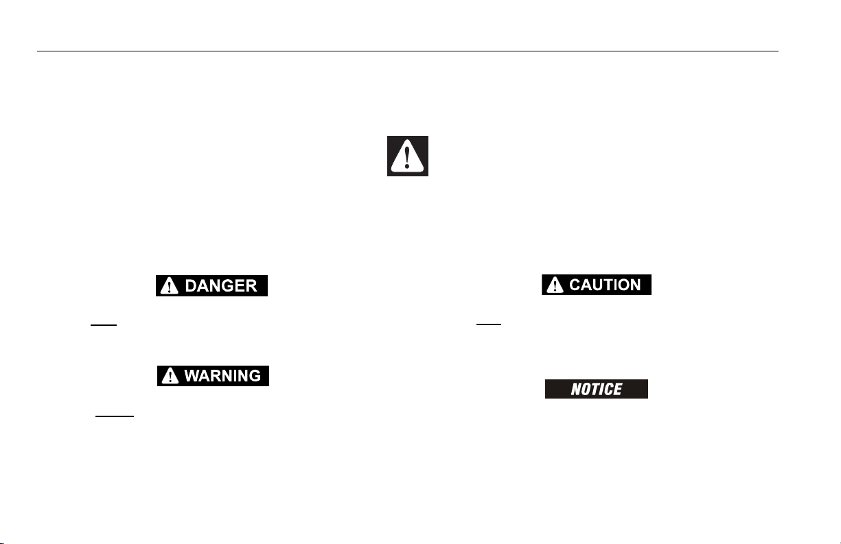
Trip and Fall Hazards
During operation, occupants in the platform must wear a full
body harness with a lanyard attached to an authorized lanyard anchorage point. Attach only one (1) lanyard per lanyard anchorage point.
3121213 – JLG Lift – 1-3
Page 14
SECTION 1 - SAFETY PRECAUTIONS
• Before operating the machine, make sure all gates are
closed and fastened in their proper position.
• Keep both feet firmly positioned on the platform floor at all
times. Never use ladders, boxes, steps, planks, or similar
items on platform to provide additional reach.
• Never use the boom assembly to enter or leave the platform.
• Use extreme caution when entering or leaving platform.
Be sure that the boom is fully lowered. It may be necessary to telescope out to position the platform closer to the
ground for entry/exit. Face the machine, maintain “three
point contact” with the machine, using two hands and one
foot or two feet and one hand during entry and exit.
Electrocution Hazards
• This machine is not insulated and does not provide protection from contact or proximity to electrical current.
1-4 – JLG Lift – 3121213
Page 15
SECTION 1 - SAFETY PRECAUTIONS
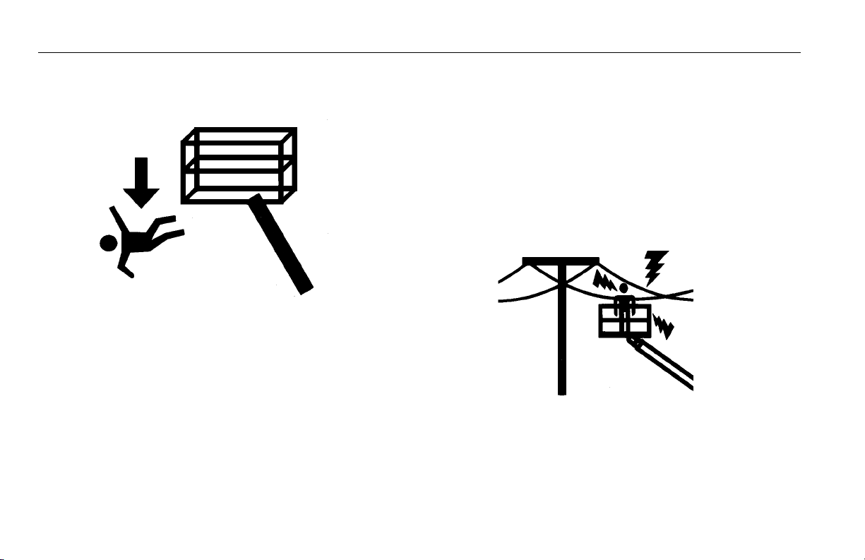
Table 1-1. Minimum Approach Distances (M.A.D.)
• Maintain distance from electrical lines, apparatus, or any
energized (exposed or insulated) parts according to the
Minimum Approach Distance (MAD) as shown in Table 1-
1.
• Allow for machine movement and electrical line swaying.
Voltage Range
(Phase to Phase)
0 to 50 KV 10 (3)
Over 50KV to 200 KV 15 (5)
Over 200 KV to 350 KV 20 (6)
Over 350 KV to 500 KV 25 (8)
Over 500 KV to 750 KV 35 (11)
Over 750 KV to 1000 KV 45 (14)
NOTE: This requirement shall apply except where
employer, local or governmental regulations
are more stringent.
• Maintain a clearance of at least 10 ft. (3m) between any part
of the machine and its occupants, their tools, and their
equipment from any electrical line or apparatus carrying up
to 50,000 volts. One foot additional clearance is required for
every additional 30,000 volts or less.
MINIMUM APPROACH DISTANCE
in Feet (Meters)
3121213 – JLG Lift – 1-5
Page 16
SECTION 1 - SAFETY PRECAUTIONS
• The minimum approach distance may be reduced if insulating barriers are installed to prevent contact, and the barriers
are rated for the voltage of the line being guarded. These
barriers shall not be part of (or attached to) the machine. The
minimum approach distance shall be reduced to a distance
within the designed working dimensions of the insulating
barrier. This determination shall be made by a qualified person in accordance with the employer, local, or governmental
requirements for work practices near energized equipment
DO NOT MANEUVER MACHINE OR PERSONNEL INSIDE PROHIBITED
ZONE (MAD). ASSUME ALL ELECTRICAL PARTS AND WIRING ARE
ENERGIZED UNLESS KNOWN OTHERWISE.
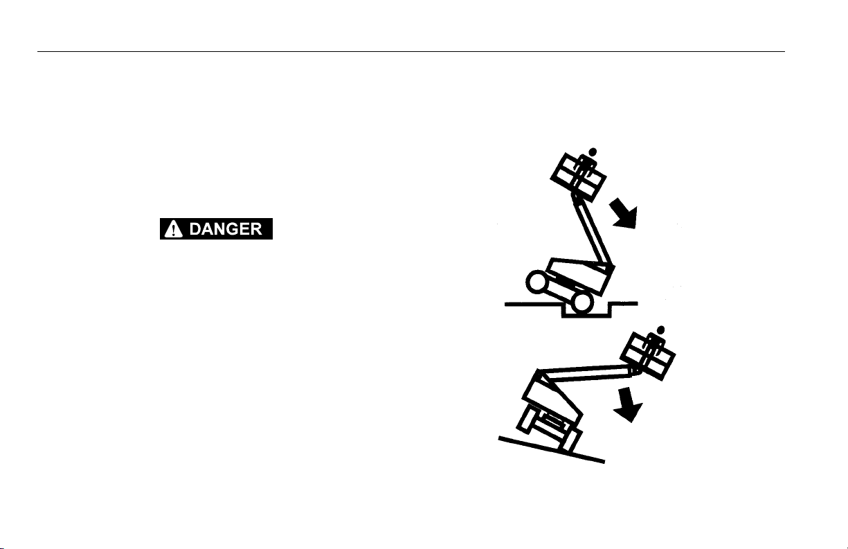
Tipping Hazards
• The user must be familiar with the surface before driving.
Do not exceed the allowable sideslope and grade while
driving.
1-6 – JLG Lift – 3121213
Page 17
SECTION 1 - SAFETY PRECAUTIONS
• Do not elevate platform or drive with platform elevated
while on a sloping, uneven, or soft surface.
• Before driving on floors, bridges, trucks, and other surfaces, check allowable capacity of the surfaces.
• Never exceed the maximum platform capacity. Distribute
loads evenly on platform floor.
• Do not raise the platform or drive from an elevated position unless the machine is on firm, level and smooth surfaces.
• Keep the chassis of the machine at least 2 ft. (0.6m) from
holes, bumps, drop-offs, obstructions, debris, concealed
holes, and other potential hazards on the floor/surface.
• Do not push or pull any object with the boom.
• Never attempt to use the machine as a crane. Do not tieoff machine to any adjacent structure.
• Do not operate the machine when wind conditions exceed
28 mph (12.5 m/s). Refer to Table 1-2, Beaufort Scale (For
Reference Only).
• Do not increase the surface area of the platform or the
load. Increase of the area exposed to the wind will
decrease stability.
• Do not increase the platform size with unauthorized deck
extensions or attachments.
• If boom assembly or platform is in a position that one or
more wheels are off the ground, all persons must be
removed before attempting to stabilize the machine. Use
cranes, forklift trucks, or other appropriate equipment to
stabilize machine.
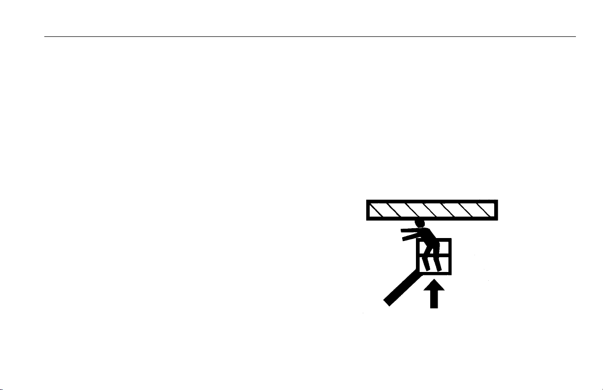
Crushing and Collision Hazards
• Approved head gear must be worn by all operating and
ground personnel.
• Check work area for clearances overhead, on sides, and
bottom of platform when lifting or lowering platform, and
driving.
• During operation, keep all body parts inside platform railing.
3121213 – JLG Lift – 1-7
Page 18

SECTION 1 - SAFETY PRECAUTIONS
• Use the boom functions, not the drive function, to position
the platform close to obstacles.
• Always post a lookout when driving in areas where vision
is obstructed.
• Keep non-operating personnel at least 6 ft. (1.8m) away
from machine during all driving and swing operations.
• Limit travel speed according to conditions of ground surface, congestion, visibility, slope, location of personnel,
and other factors which may cause collision or injury to
personnel.
• Be aware of stopping distances in all drive speeds. When
driving in high speed, switch to low speed before stopping. Travel grades in low speed only.
• Do not use high speed drive in restricted or close quarters
or when driving in reverse.
• Exercise extreme caution at all times to prevent obstacles
from striking or interfering with operating controls and persons in the platform.
• Be sure that operators of other overhead and floor level
machines are aware of the aerial work platform’s presence. Disconnect power to overhead cranes.
• Warn personnel not to work, stand, or walk under a raised
boom or platform. Position barricades on floor if necessary.
1.4 TOWING, LIFTING, AND HAULING
• Never allow personnel in platform while towing, lifting, or
hauling.
• This machine should not be towed, except in the event of
emergency, malfunction, power failure, or loading/unloading. Refer to the Emergency Procedures section of this
manual for emergency towing procedures.
• Ensure boom is in the stowed position and the turntable
locked prior to towing, lifting or hauling. The platform must
be completely empty of tools.
• When lifting machine, lift only at designated areas of the
machine. Lift the unit with equipment of adequate capacity.
• Refer to the Machine Operation section of this manual for
lifting information.
1-8 – JLG Lift – 3121213
Page 19

SECTION 1 - SAFETY PRECAUTIONS
1.5 ADDITIONAL HAZARDS / SAFETY
• Do not use machine as a ground for welding.
• When performing welding or metal cutting operations,
precautions must be taken to protect the chassis from
direct exposure to weld and metal cutting spatter.
• Do not refuel the machine with the engine running.
• Battery fluid is highly corrosive. Avoid contact with skin
and clothing at all times.
• Charge batteries only in a well ventilated area.
3121213 – JLG Lift – 1-9
Page 20
SECTION 1 - SAFETY PRECAUTIONS
DO NOT OPERATE THE MACHINE WHEN WIND CONDITIONS EXCEED 28
MPH (12.5 M/S).
Table 1-2. Beaufort Scale (For Reference Only)
Beaufort
Number
0 0 0-0.2 Calm Calm. Smoke rises vertically.
1 1-3 0.3-1.5 Light air Wind motion visible in smoke.
2 4-7 1.6-3.3 Light breeze Wind felt on exposed skin. Leaves ru stle.
3 8-12 3.4-5.4 Gentle breeze Leaves and smaller twigs in constant motion.
4 13-18 5.5-7.9 Moderate breeze Dust and loose paper raised. Small branches begin to move.
5 19-24 8.0-10.7 Fresh breeze Smaller trees sway.
6 25-31 10.8-13.8 Strong breeze Large branches in motion. Whistling heard in overhead wires.
7 32-38 13.9-17.1 Near Gale/Moderate Gale Whole trees in motion. Effor t needed to walk against the wind.
8 39-46 17.2-20.7 Fresh Gale Twigs broken from trees. Cars veer on road.
9 47-54 20.8-24.4 Strong Gale Light structure damage.
Wind Speed
mph m/s
Description Land Conditions
Umbrella use becomes difficult.
1-10 – JLG Lift – 3121213
Page 21

SECTION 2 - USER RESPONSIBILITIES, MACHINE PREPARATION, AND INSPECTION
SECTION 2. USER RESPONSIBILITIES, MACHINE PREPARATION, AND INSPECTION
2.1 PERSONNEL TRAINING
The aerial platform is a personnel handling device; so it is
necessary that it be operated and maintained only by trained
personnel.
Persons under the influence of drugs or alcohol or who are
subject to seizures, dizziness or loss of physical control must
not operate this machine.
Operator Training
Operator training must cover:
1. Use and limitations of the controls in the platform and at
the ground, emergency controls and safety systems.
2. Control labels, instructions, and warnings on the
machine.
3. Rules of the employer and government regulations.
4. Use of approved fall protection device.
5. Enough knowledge of the mechanical operation of the
machine to recognize a malfunction or potential malfunction.
6. The safest means to operate the machine where overhead obstructions, other moving equipment, and obstacles, depressions, holes, drop-offs.
7. Means to avoid the hazards of unprotected electrical
conductors.
8. Specific job requirements or machine application.
Training Supervision
Training must be done under the supervision of a qualified
person in an open area free of obstructions until the trainee
has developed the ability to safely control and operate the
machine.
Operator Responsibility
The operator must be instructed that he/she has the responsibility and authority to shut down the machine in case of a
malfunction or other unsafe condition of either the machine
or the job site.
3121213 – JLG Lift – 2-1
Page 22

SECTION 2 - USER RESPONSIBILITIES, MACHINE PREPARATION, AND INSPECTION
2.2 PREPARATION, INSPECTION, AND MAINTENANCE
The following table covers the periodic machine inspections
and maintenance required by JLG Industries, Inc. Consult
local regulations for further requirements for aerial work platforms. The frequency of inspections and maintenance must
be increased as necessary when the machine is used in a
harsh or hostile environment, if the machine is used with
increased frequency, or if the machine is used in a severe
manner.
JLG INDUSTRIES, INC. RECOGNIZES A FACTORY-QUALIFIED SERVICE
TECHNICIAN AS A PERSON WHO HAS SUCCESSFULLY COMPLETED
THE JLG SERVICE TRAINING SCHOOL FOR THE SPECIFIC JLG PRODUCT
MODEL.
2-2 – JLG Lift – 3121213
Page 23

SECTION 2 - USER RESPONSIBILITIES, MACHINE PREPARATION, AND INSPECTION
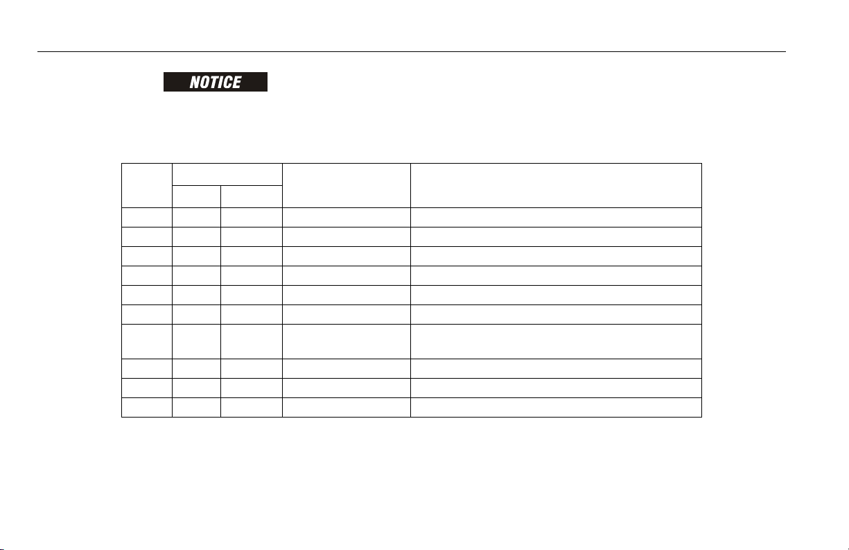
Table 2-1. Inspection and Maintenance Table
Type Frequency
Pre-Start Inspection Before using each day; or
whenever there’s an Operator change.
Pre-Delivery Inspection (See
Note)
Freque nt Inspec tion
(See Note)
Annual Machine Inspection
(See Note)
Preventative Maintenance At intervals as specified in the Service and Main-
NOTE: Inspection forms are available from JLG. Use the Service and Maintenance Manual to perform inspections.
Before each sale, lease, or rental delivery. Owner, Dealer, or User Qualified JLG
In service for 3 months or 150 hours, whichever
comes first;
o r
Out of service for a period of more than 3 months;
o r
Purchased used.
Annually, no later than 13 months from the date of
prior inspection.
tenance Manual.
Primary
Responsibility
User or Operator User or Operator Operator and Safety Manual
Owner, Dealer, or User Qualified JLG
Owner, Dealer, or User Factory Qualified
Owner, Dealer, or User Qualified JLG
Service
Qualification
Mechanic
Mechanic
Service Technician
(Recommended)
Mechanic
Service and Maintenance
Manual and applicable JLG
inspection form
Service and Maintenance
Manual and applicable JLG
inspection form
Service and Maintenance
Manual and applicable JLG
inspection form
Service and Maintenance
Manual
Reference
3121213 – JLG Lift – 2-3
Page 24
SECTION 2 - USER RESPONSIBILITIES, MACHINE PREPARATION, AND INSPECTION
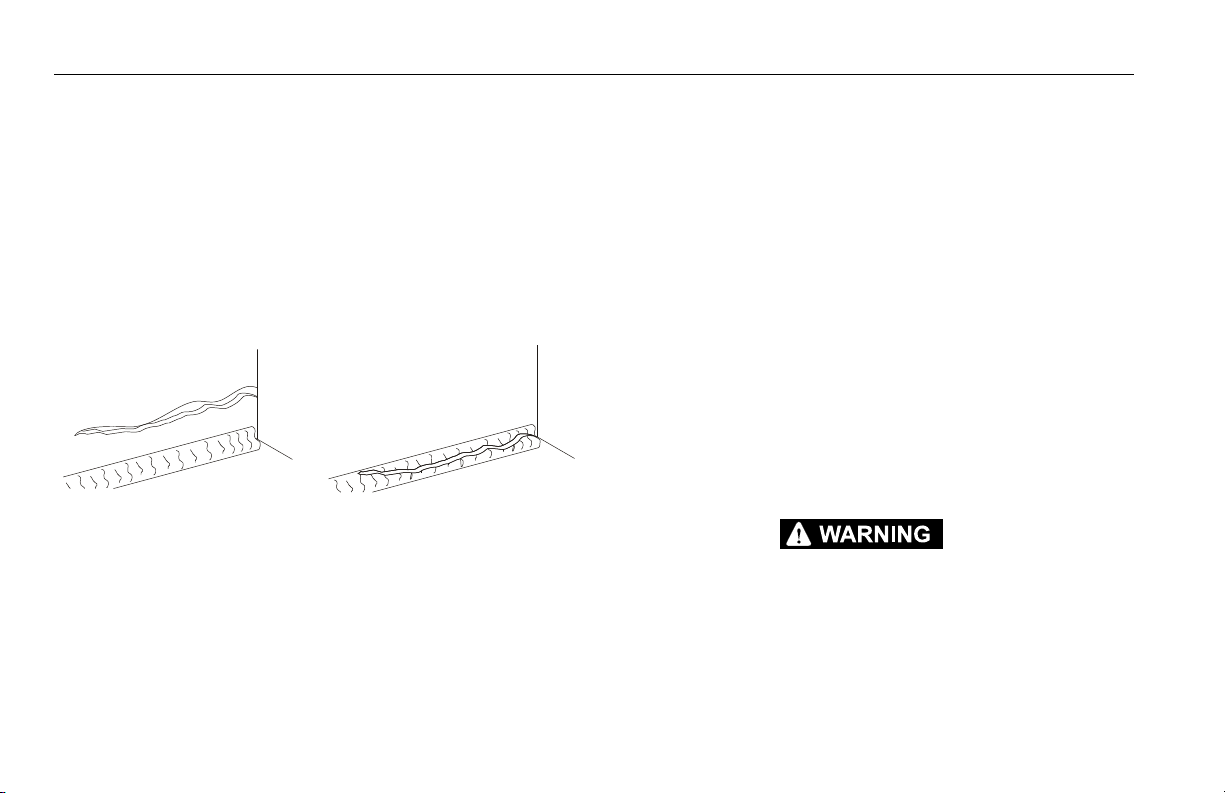
Pare nt Metal C rack Weld Crack
Pre-Start Inspection
The Pre-Start Inspection should include each of the following:
1. Cleanliness – Check all surfaces for leakage (oil, fuel,
or battery fluid) or foreign objects. Report any leakage to
the proper maintenance personnel.
2. Structure - Inspect the machine structure for dents,
damage, weld or parent metal cracks or other discrepancies.
3. Decals and Placards – Check all for cleanliness and
legibility. Make sure none of the decals and placards are
missing. Make sure all illegible decals and placards are
cleaned or replaced.
4. Operators and Safety Manuals – Make sure a copy of
the Operator and Safety Manual, EMI Safety Manual
(Domestic only), and ANSI Manual of Responsibilities
(Domestic only) is enclosed in the weather resistant
storage container.
5. “Walk-Around” Inspection – Refer to Figure 2-1. thru
Figure 2-4.
6. Battery – Charge as required.
7. Fuel (Combustion Engine Powered Machines) – Add the
proper fuel as necessary.
8. Engine Oil Supply - Ensure the engine oil level is at the
Full mark on the dipstick and the filler cap is secure.
9. Hydraulic Oil – Check the hydraulic oil level. Ensure
hydraulic oil is added as required.
10. Function Check – Once the “Walk-Around” Inspection
is complete, perform a functional check of all systems in
an area free of overhead and ground level obstructions.
Refer to Section 4 for more specific instructions.
IF THE MACHINE DOES NOT OPERATE PROPERLY, TURN OFF THE
MACHINE IMMEDIATELY! REPORT THE PROBLEM TO THE PROPER
MAINTENANCE PERSONNEL. DO NOT OPERATE THE MACHINE UNTIL IT
IS DECLARED SAFE FOR OPERATION.
2-4 – JLG Lift – 3121213
Page 25

SECTION 2 - USER RESPONSIBILITIES, MACHINE PREPARATION, AND INSPECTION
Function Check
Perform the Function Check as follows:
1. From the ground control panel with no load in the platform:
a. Check that all guards protecting the switches or
locks are in place;
b. Operate all functions and check all limiting and cut-
out switches;
c. Check auxiliary power (or manual descent);
d. Ensure that all machine functions are disabled
when the Emergency Stop Button is activated.
2. From the platform control console:
a. Ensure that the control console is firmly secured in
the proper location;
b. Check that all guards protecting the switches or
locks are in place;
c. Operate all functions and check all limiting and cut-
out switches;
d. Ensure that all machine functions are disabled
when the Emergency Stop Button is pushed in.
3. With the platform in the transport (stowed) position:
a. Drive the machine on a grade, not to exceed the
rated gradeability, and stop to ensure the brakes
hold;
b. Check the tilt sensor alarm to ensure proper opera-
tion.
3121213 – JLG Lift – 2-5
Page 26
SECTION 2 - USER RESPONSIBILITIES, MACHINE PREPARATION, AND INSPECTION
Figure 2-1. Daily Walk-Around Inspection - Sheet 1 of 4
2-6 – JLG Lift – 3121213
Page 27

SECTION 2 - USER RESPONSIBILITIES, MACHINE PREPARATION, AND INSPECTION
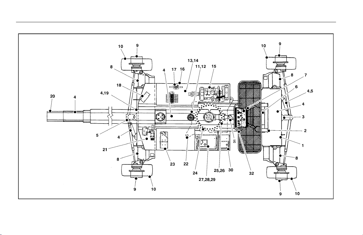
GENERAL
Begin the "Walk-Around Inspection" at Item 1, as noted on the
diagram. Continue to the right (counterclockwise viewed from
top) checking each item in sequence for the conditions listed
in the following checklist.
TO AVOID POSSIBLE INJURY, BE SURE MACHINE POWER IS OFF.
DO NOT OPERATE MACHINE UNTIL ALL MALFUNCTIONS HAVE BEEN
CORRECTED.
INSPECTION NOTE: On all components, make sure there are
no loose or missing parts, that they are securely fastened, and
no visible damage, leaks or excessive wear exists in addition
to any other criteria mentioned.
1. Rear Frame Deck - Deck clean and free of grease
and oil; deck treads in place and undamaged.
2. Platform Access Ladder - See Inspection Note.
3. Axle Jack/Extension Switches - See Inspection
Note; decals in place and legible.
4. All Hydraulic Cylinders - No visible damage; pivot
pins and hydraulic hoses undamaged, not leaking.
5. Tie Rods and Steering Linkage - No loose, bent, or
missing parts; no visible damage; tie rod ends
undamaged.
6. Platform Assembly - See Inspection Note. Footswitch in good working order; not modified, disabled,
or blocked. Gate interlock functioning properly. Intercom properly secured and operating.
7. Platform Control Console - Switches and controllers
properly secured; no loose or missing parts; information and operating placards are in place and legible;
controllers and switches return to neutral; control
markings legible. Capacity indicator properly secured;
no visible damage; operating properly.
8. Extendable Axle - See Inspection Note. Power track
and hydraulic hoses secure and undamaged; no evidence of leakage.
Figure 2-2. Daily Walk-Around Inspection - Sheet 2 of 4
3121213 – JLG Lift – 2-7
Page 28

SECTION 2 - USER RESPONSIBILITIES, MACHINE PREPARATION, AND INSPECTION
9. Drive Hub, Drive Motor and Drive Brake - See
Inspection Note.
10. Steer/Drive Wheel/Tire Assembly - Properly
secured; no loose or missing lug nuts; no visible damage.
11. Hose and Cable Guards/Clamps - See Inspection
Note.
12. Power Track - See Inspection Note.
13. Muffler and Exhaust System - See Inspection Note.
14. Engine Air Filter Assembly - See Inspection Note;
element clean.
15. Engine Oil Supply - Full mark on dipstick; filler cap
secure.
16. Cowling and Latches - All cowling, doors, and
latches in working condition; See Inspection Note.
17. Control Valve Compartment - See Inspection Note.
18. Ground Controls - Switches and controllers opera-
ble; no visible damage; placards secure and legible.
19. Axle Jack/Extension Switches - See Inspection
Note; decals in place and legible.
20. Main Boom Pivot Pin - See Inspection Note.
21. Manual Descent Valves and Pump - Valve handles
and pump handle properly secured. Instruction placards in place and legible.
22. Turntable Lock - Operable; See Inspection Note.
23. Battery - Proper electrolyte level; cables tight; no visi-
ble damage or corrosion.
24. Turntable Bearing and Pinion - See Inspection Note.
No evidence of loose bolts or looseness between
bearing and structure.
Figure 2-3. Daily Walk-Around Inspection - Sheet 3 of 4
2-8 – JLG Lift – 3121213
Page 29

SECTION 2 - USER RESPONSIBILITIES, MACHINE PREPARATION, AND INSPECTION
25. Boom Limit Switches - Properly secured; no damage
to cams or switches; cams free from excess dirt and
grease.
26. Boom Sections - No visible damage; wear pads
secure; boom chain adjusting nuts secure and
undamaged; lift and telescope cylinders - rod end
shafts and barrel end shafts properly secured; no evidence of leakage; evidence of proper lubrication.
27. Hydraulic Oil Supply - Recommended oil level.
(Check level with cold oil, systems shut down,
machine in stowed position.) Cap secure and in place.
28. Oil Filter Housing - See Inspection Note.
29. Hydraulic Oil Breather - Element in place; not
clogged; no visible signs of overflow.
30. Fuel Supply - Fuel filler cap secure. Tank - See
Inspection Note.
31. Platform Pivot and Slave Cylinder Attach Pins - See
Inspection Note.
32. Frame - No visible damage; no loose or missing hardware (top and underside).
Figure 2-4. Daily Walk-Around Inspection - Sheet 4 of 4
3121213 – JLG Lift – 2-9
Page 30

SECTION 2 - USER RESPONSIBILITIES, MACHINE PREPARATION, AND INSPECTION
2.3 DAILY FUNCTIONAL CHECK
A functional check of all systems should be performed, under
no load, once the walk-around inspection is complete, in an
area free of overhead and ground level obstructions. First, using
the ground controls, check all functions controlled by the
ground controls. Next, using the platform controls, check all
functions controlled by the platform controls.
TO AVOID SERIOUS INJURY, DO NOT OPERATE MACHINE IF ANY CONTROLLERS OR TOGGLE SWITCHES CONTROLLING PLATFORM MOVEMENTS DO NOT RETURN TO THE OFF POSITION WHEN RELEASED.
TO AVOID A COLLISION AND INJURY IF PLATFORM DOES NOT STOP
WHEN A CONTROL SWITCH OR CONTROLLER IS RELEASED, REMOVE
FOOT FROM FOOTSWITCH OR USE EMERGENCY STOP TO STOP
MACHINE.
Axle Extension System
WHEN RAISING FRAME TO OPERATE AXLE EXTENSION SYSTEM, RAISE
ONLY ONE JACK CYLINDER AT A TIME. DO NOT RAISE BOTH CYLINDERS AT THE SAME TIME, AS THIS WILL CAUSE THE MACHINE TO
BECOME UNSTABLE.
1. From ground controls, activate the machine hydraulic
system.
2. Position JACK cylinder switch on axle to DOWN and
hold until wheels rise from the ground.
3. Remove lock pin from left tie rod.
4. Position EXTEND/RETRACT switch for front axle to
extend until the left axle is fully extended. White tape on
axle beam must be completely exposed to indicate full
extension of axle. Install left tie rod lock pin.
5. Remove lock pin from right tie rod.
6. Position EXTEND/RETRACT switch for front axle to
extend until the right axle is fully extended. White tape
on axle beam must be completely exposed to indicate
full extension of axle. Install right tie rod lock pin.
7. Position JACK cylinder switch to UP to lower the
machine wheels.
8. Check AXLES SET indicator light to ensure it is illuminated.
9. Repeat steps (2) through (8) for rear axle.
2-10 – JLG Lift – 3121213
Page 31

SECTION 2 - USER RESPONSIBILITIES, MACHINE PREPARATION, AND INSPECTION
Axle Retraction System
1. From ground controls, activate the machine hydraulic
system.
2. Position JACK cylinder switch on axle to DOWN and
hold until wheels rise from the ground.
3. Remove lock pin from left tie rod.
4. Position EXTEND/RETRACT switch for front axle to
retract until the left axle is fully retracted. Install left tie
rod lock pin.
5. Remove lock pin from right tie rod.
6. Position EXTEND/RETRACT switch for front axle to
retract until the right axle is fully retracted. Install right tie
rod lock pin.
7. Position JACK cylinder switch to UP to lower the
machine wheels.
8. Repeat steps (2) through (7) for rear axle.
Function Cut-Outs and Restrictions
1. Platform Gate Interlock
The engine will not start unless the platform gate is
closed and latched.
2. Swing Cut-Out
With axles retracted, boom will only swing between drive
tires.
3. Tow er Te l e s c o p e C ut - O u t
With axles retracted, tower boom will not telescope.
Only main boom will telescope.
WITH AXLES RETRACTED AND MAIN BOOM EXTENDED, DO NOT
ATTEMPT TO RAISE AND EXTEND AXLE THAT MAIN BOOM IS
EXTENDED OVER. RETRACT MAIN BOOM BEFORE ATTEMPTING TO
RAISE AND EXTEND AXLE.
3121213 – JLG Lift – 2-11
Page 32

SECTION 2 - USER RESPONSIBILITIES, MACHINE PREPARATION, AND INSPECTION
4. Tower Boom Horizontal Cut-Out
With the tower boom above horizontal, HIGH DRIVE and
2 SPEED are cut out. In addition, with tower boom
above horizontal, selecting DRIVE or MAIN LIFT cuts out
HIGH ENGINE on TOWER LIFT and TOWER TELESCOPE functions, DRIVE function automatically goes to
CREEP mode, and HIGH ENGINE is cut out except as
noted in step (9).
5. Axles/Axles Jack Cut-Out
To retract axles or operate axle jacks, ground controls
must be selected, booms must be below horizontal and
between drive wheels.
6. 5° Tilt Cut-Out
When machine is on a 5° slope, 2 speed is cut out,
regardless of tower boom position. In addition, if tower
boom is above horizontal with machine on a 5° slope,
drive function is cut out and all other functions automatically go into creep mode.
7. Tower Boom Cut-Outs
Tower telescope and main lift are cut out unless tower lift
is fully up. Tower lift is cut out unless tower telescope is
fully in and main lift is fully down.
8. Main Boom Lift Cut-Out
When main boom lift is operating, lift speed automatically goes into the creep mode 18° before each end of
the lift cylinder stroke.
9. Tower Lift and Tower Telescope Cut-Outs
When activating Tower Lift UP or DOWN or Tower Telescope IN or OUT, high engine is activated at full controller stroke. This feature can be turned off at platform
controls using HIGH ENGINE switch.
10. Auxiliary Power
When auxiliary power is activated, the CREEP function
does not work. In addition, if engine is running and auxiliary power is activated, the engine will shut off. This
prevents the operator from increasing function speeds.
2-12 – JLG Lift – 3121213
Page 33

SECTION 2 - USER RESPONSIBILITIES, MACHINE PREPARATION, AND INSPECTION
SIDE VIEW: MAIN BOOM AND
TOWER BOOM AT TACH
TOP VIEW: BOOM AT TACH
TO TURNTABLE
Tower Boo m S eq uence
1. Place the machine on level ground and with the tower
boom in the stowed position. Identify the hydraulic valve
switch adjacent to the tower lift cylinder at the bottom
end (rear) of the tower base boom.
2. Visually check the two valves in the turntable to ensure
the plungers are fully extended
.
3121213 – JLG Lift – 2-13
Page 34

SECTION 2 - USER RESPONSIBILITIES, MACHINE PREPARATION, AND INSPECTION
NOTE: If the plunger is not fully extended, contact a qualified ser-
vice technician to further evaluate this condition before
operating the machine.
3. Try to extend the tower boom assembly.
NOTE: The boom should not extend and the red check light in
the ground console panel should illuminate. If the light
does not come on, contact a qualified service technician
to further evaluate this condition before operating the
machine.
4. Try to raise the main boom assembly.
NOTE: The boom should not raise and the red check light in the
ground console panel should illuminate. If the light does
not come on, contact a qualified service technician to further evaluate this condition before operating the machine.
5. Attempt to lower the tower base boom with the tower fly
boom extended.
NOTE: The tower base boom should not lower and the red check
light in the ground console should illuminate. If the light
does not come on, contact a qualified service technician
to further evaluate this condition before operating the
machine.
6. Fully retract the tower boom. Lift the main boom several
feet. Attempt to lower the tower boom.
NOTE: Tower Lift down should not work and the red check light
in the ground console panel should illuminate. If the light
does not come on, contact a qualified service technician
to further evaluate this condition before operating the
machine.
Tower Boom Lift and Swing Systems
Raise and lower tower boom, then swing tower boom to
LEFT and RIGHT as swing cut-out will allow. Cycle functions
several times. Check for smooth elevation and swing motion.
Tower Boom Telescope System
Telescope tower boom IN and OUT several cycles at various
degrees of elevation. Check for smooth telescope operation.
Main Boom Lift System
Raise and lower main boom several times. Check for smooth
operation.
Main Boom Telescope System
Telescope main boom IN and OUT several cycles at various
degrees of elevation. Check for smooth telescope operation.
2-14 – JLG Lift – 3121213
Page 35

SECTION 2 - USER RESPONSIBILITIES, MACHINE PREPARATION, AND INSPECTION
Platform Leveling Systems
Check that platform automatic self-leveling system functions
properly during raising and lowering of boom.
Check platform level adjustment system for proper operation.
Platform Rotator
Check rotator for smooth operation and assure platform will
rotate 90 degrees in both directions from centerline of boom.
Drive System
Drive machine forward and reverse; check for proper operation.
Steer System
Steer machine left and right; check for proper operation.
Footswitch
FOOTSWITCH MUST BE ADJUSTED SO THAT FUNCTIONS WILL OPERATE WHEN PEDAL IS APPROXIMATELY AT ITS CENTER OF TRAVEL. IF
SWITCH OPERATES WITHIN LAST 1/4" OF TRAVEL, TOP OR BOTTOM, IT
SHOULD BE ADJUSTED.
1. Activate hydraulic system. Activate footswitch. Operate
TOWER BOOM TELESCOPE and hold controller.
Remove foot from footswitch, motion should stop. If it
does not, shut down machine and contact a qualified
service technician.
2. With hydraulic system and footswitch activated, operate
MAIN BOOM LIFT and hold control. Remove foot from
footswitch, motion should stop. If it does not, shut down
machine and contact a qualified service technician.
3. With hydraulic power shut down, place foot on footswitch. Attempt to start engine. Engine should not
attempt to start when footswitch is engaged. If starter
engages or engine turns over, shut down machine and
contact a qualified service technician.
Auxiliary Power
Operate each function control switch or controller (e.g.
TELE, LIFT, SWING) to assure that they function in both
directions using auxiliary power instead of engine power.
Ground Controls
Place GROUND/PLATFORM SELECT switch to GROUND.
Start engine. Platform controls should not operate.
3121213 – JLG Lift – 2-15
Page 36

SECTION 2 - USER RESPONSIBILITIES, MACHINE PREPARATION, AND INSPECTION
NOTES:
2-16 – JLG Lift – 3121213
Page 37

SECTION 3 - MACHINE CONTROLS AND INDICATORS
SECTION 3. MACHINE CONTROLS AND INDICATORS
3.1 GENERAL
THE MANUFACTURER HAS NO DIRECT CONTROL OVER MACHINE
APPLICATION AND OPERATION. THE USER AND OPERATOR ARE
RESPONSIBLE FOR CONFORMING WITH GOOD SAFETY PRACTICES.
This section provides the necessary information needed to
understand control functions.
3.2 CONTROLS AND INDICATORS
The Model 150HAX is equipped with control panels that
use symbols and words to indicate control functions. On
some machines, the control panels may use symbols
only.
NOTE: The Ground Control Station consists of two parts, the sta-
tionary Ground Control Panel, and the movable Ground
Control Remote Box. The remote box can be removed
from the ground control station, and is attached to the
machine by a 50 foot (15 m) cable. This will allow the
operator to control platform movement away from the
machine to gain a better view of the platform location.
Ground Control Panel
DO NOT OPERATE FROM GROUND CONTROL STATION WITH PERSONNEL IN THE PLATFORM EXCEPT IN AN EMERGENCY.
PERFORM AS MANY PRE-OPERATIONAL CHECKS AND INSPECTIONS
FROM THE GROUND CONTROL STATION AS POSSIBLE.
NOTE: When the machine is shut down the master switch must
be positioned to OFF to prevent draining the battery and
burning ignition points.
1. Master Switch (Prior to S/N 46291)
A two-position key operated switch furnishes electrical
power to the IGNITION ON relays, the EMERGENCY
STOP switch and to the PLATFORM/GROUND SELECT
SWITCH when in the ON position.
3121213 – JLG Lift – 3-1
Page 38

SECTION 3 - MACHINE CONTROLS AND INDICATORS
2. Platform/Ground Select Switch
A three-position, center-off PLATFORM/GROUND
SELECT SWITCH supplies operating power to the controls on the platform control console, when positioned to
PLATFORM. With the switch in GROUND position,
power is shut off to the controls at the platform station,
and only the controls on the ground control panel and
remote box are operable.
NOTE: With the PLATFORM/GROUND SELECT SWITCH in the
center position, power is shut off to controls at both operating stations.
3. Axles Set Indicator Light
The AXLES SET indicator light is illuminated when the
axles are fully extended and locked in place.
4. High Engine Circuit Breaker
A rocker-type push button reset 30 Amp circuit breaker
returns interrupted power to the high engine function
when depressed.
5. Hourmeter
An HOURMETER records the engine operating time.
6. Voltmeter
With the ignition switch in the ON position, and before
starting the engine, the VOLTMETER indicates the condition of the battery. With the engine running, the VOLTMETER indicates output voltage of the alternator.
Normal reading for the voltmeter will be 12-14 volts with
a properly charged or charging battery.
7. Oil Pressure Gauge
An OIL PRESSURE gauge provides an indication of the
engine lubrication system pressure.
8. Water Temperature Gauge
A WATER TEMPERATURE gauge provides an indication
of the coolant temperature within the engine.
9. Tower Proximity Switch Check Light
Indicates that the ground control tower lift, main lift or
telescope function switch is being selected with the
tower or main boom outside of the allowable operating
range. Refer to Daily Functional Check, Tower Boom
Sequence in Section 2.
3-2 – JLG Lift – 3121213
Page 39

SECTION 3 - MACHINE CONTROLS AND INDICATORS
Figure 3-1. Ground Control Panel - Sheet 1 of 3
1. Master Switch
2. Platform/Ground Select Switch
3. Axles Set Indicator
4. High Engine Circuit Breaker
5. Hourmeter
6. Voltmeter
7. Oil Pressure Gauge
8. Water Temperature Gauge
3121213 – JLG Lift – 3-3
Page 40

SECTION 3 - MACHINE CONTROLS AND INDICATORS
Figure 3-2. Ground Control Panel - Sheet 2 of 3
1. Master Switch
2. Platform/Ground Select Switch
3. Axles Set Indicator
4. High Engine Circuit Breaker
5. Hourmeter
6. Voltmeter
7. Oil Pressure Gauge
8. Water Temperature Gauge
3-4 – JLG Lift – 3121213
Page 41

SECTION 3 - MACHINE CONTROLS AND INDICATORS
Figure 3-3. Ground Control Panel - Sheet 3 of 3
1. N/A
2. Platform/Ground Select Switch
3. Axles Set Indicator
4. High Engine Circuit Breaker
5. Hourmeter
6. Voltmeter
7. Oil Pr essure Gauge
8. Water Temperature Gauge
9. Tower Proximity Switch Check Indicator
3121213 – JLG Lift – 3-5
Page 42

SECTION 3 - MACHINE CONTROLS AND INDICATORS
Ground Control Remote Box
NOTE: If equipped, the Function Enable switch must be held
down in order to operate Main Boom Telescope, Tower
Lift, Swing, Main Lift, Platform Level Override, and Platform Rotate functions.
1. Auxiliary Power Switch
A toggle-type AUXILIARY POWER control switch, energizes the electrically operated auxiliary hydraulic pump,
when actuated. (Switch must be held ON for duration of
auxiliary pump use.)
a. The auxiliary pump functions to provide sufficient oil
flow to operate the basic machine system should
the main pump or engine fail during operation. The
auxiliary pump enables the boom lift, telescope,
swing and platform level functions to be operated.
b. It should be noted that functions will operate at a
slower than normal rate because of the lower gpm
delivered.
NOTE: When operating on auxiliary power, do not operate more
than one function at a time. Simultaneous operation can
overload the 12-volt auxiliary pump motor.
c. Position PLATFORM/GROUND SELECT SWITCH to
GROUND.
d. Position MASTER SWITCH to ON.
e. Operate appropriate switch for desired function and
direction.
f. Position AUXILIARY POWER SWITCH to ON and
hold.
g. Release both AUXILIARY POWER SWITCH TO ON
AND HOLD AND SELECTED FUNCTION SWITCH.
h. Position MASTER SWITCH to OFF
TO AVOID SERIOUS INJURY, DO NOT OPERATE MACHINE IF ANY CONTROLLERS OR TOGGLE SWITCHES CONTROLLING PLATFORM MOVEMENT DO NOT RETURN TO THE OFF POSITION WHEN RELEASED.
2. Platform Rotate Switch
A three-position ROTATE control switch permits rotation
of the platform when positioned LEFT or RIGHT.
3-6 – JLG Lift – 3121213
Page 43

SECTION 3 - MACHINE CONTROLS AND INDICATORS
Figure 3-4. Ground Control Remote Box
1. Auxiliary Power
2. Platform Rotate
3. Platform Leveling Override
4. Start
5. Creep Speed
6. Emergency Stop
7. Main Telescope
8. Swing
9. Tower Telescope
10. Tower Lift
11. Main Lift
12. Manual Descent Valves (Not Shown)
13. Function Enable
14. Platform Overload
3121213 – JLG Lift – 3-7
Page 44

SECTION 3 - MACHINE CONTROLS AND INDICATORS
6. Emergency Stop Button
ONLY USE THE PLATFORM LEVELING OVERRIDE FUNCTION FOR
SLIGHT LEVELING OF THE PLATFORM. INCORRECT USE COULD CAUSE
THE LOAD/OCCUPANT TO SHIFT OR FALL. FAILURE TO DO SO COULD
RESULT IN DEATH OR SERIOUS INJURY.
3. Platform Leveling Override
A three position switch allows the operator to adjust the
automatic self leveling system. This switch is used to
adjust platform level in situations such as ascending/
descending a grade.
4. Start Switch
A momentary contact, push button type switch that,
when depressed, supplies electrical power to the starter
solenoid when the MASTER SWITCH and IGNITION/
EMERGENCY STOP switches are in the ON position.
5. Creep Speed Switch
The Creep Speed Switch allows the operator to select a
lower speed for machine functions when positioned to
on.
The EMERGENCY STOP button supplies electrical
power from the IGNITION ON relays to the START button when the button is pulled out and the MASTER
SWITCH is in the ON position. When depressed, the button shuts off electrical power to the machine.
7. Main Telescope Controller
The MAIN TELESCOPE controller provides extension
and retraction of the main boom when positioned to IN
or OUT.
8. Swing Controller
The SWING controller provides 360° continuous turntable rotation. To activate SWING, position and hold controller to LEFT or RIGHT.
NOTE: Controllers and switches controlling platform movement
automatically return to the center off position when
released.
9. Tower Telescope Controller
The TOWER TELESCOPE controller provides extension
and retraction of the tower boom when positioned to IN
or OUT.
3-8 – JLG Lift – 3121213
Page 45

SECTION 3 - MACHINE CONTROLS AND INDICATORS
10. Tower Lift Controller
The TOWER LIFT controller provides raising and lowering of the tower boom when positioned to UP or DOWN.
11. Main Lift Controller
The MAIN LIFT controller provides raising and lowering
of the main boom when positioned to UP or DOWN.
12. Manual Descent Valves (Not Shown)
The manual descent valves are located on the left front
of the machine turntable. The manual descent valves
should be used, in the event of a total power failure, to
lower the work platform in the event of an emergency.
The valves permit the use of gravity to retract the tower
boom and lower the main boom. Refer to Section 6 for a
complete description of the manual descent systems,
their application and their operation.
13. Function Enable
If equipped, the enable switch must be held "DOWN" to
enable all boom controls when the engine is running.
14. Platform Overload (If equipped)
Indicates the platform has been overloaded.
3121213 – JLG Lift – 3-9
Page 46

SECTION 3 - MACHINE CONTROLS AND INDICATORS
Platform Control Station
ONLY USE THE PLATFORM LEVELING OVERRIDE FUNCTION FOR
SLIGHT LEVELING OF THE PLATFORM. INCORRECT USE COULD CAUSE
THE LOAD/OCCUPANT TO SHIFT OR FALL. FAILURE TO DO SO COULD
RESULT IN DEATH OR SERIOUS INJURY.
WHEN DRIVING FORWARD AND OPERATING THE REAR STEER
WHEELS, THE REAR WHEELS WILL TURN IN THE OPPOSITE DIRECTION
OF MACHINE TRAVEL, I.E., DEPRESSING THE LEFT SIDE OF THE
ROCKER SWITCH WILL CAUSE THE WHEELS TO TURN TO THE RIGHT.
3. Tower Telescope Controller
1. Platform Leveling Override
A three position switch allows the operator to adjust the
automatic self leveling system. This switch is used to
adjust platform level in situations such as ascending/
descending a grade.
2. Drive/Steer Controller
The DRIVE/STEER controller operates two functions:
Drive and Rear Steer. Positioning the controller handle
forward operates Drive Forward, and positioning the
handle to the rear operates Drive Reverse. The rocker
switch on top of the controller handle operates the steer
function for the rear wheels. Depressing the left side of
the rocker switch will cause the machine to steer to the
left, and depressing the right side of the rocker switch
will cause the machine to steer to the right.
The TOWER TELESCOPE controller provides extension
and retracting of the tower boom when positioned to IN
or OUT.
4. Start Button
The START button is a momentary contact, push button
type switch. With the MASTER SWITCH positioned to
ON and the START button depressed, electrical power is
supplied to the starter solenoid.
5. Choke/Glow Plug Switch (If Equipped)
The optional CHOKE/GLOW PLUG switch is used to
assist cold engine starting. For diesel engines, the
switch activates glow plugs in the engine to warm the
diesel fuel for easier starting. On gasoline engines, the
switch activates the choke to deliver a richer fuel mixture
for easier starting.
3-10 – JLG Lift – 3121213
Page 47

SECTION 3 - MACHINE CONTROLS AND INDICATORS
Figure 3-5. Platform Control Station
1. Platform Leveling Override
2. Drive/Steer Lever
3. Tower Telescope Lever
4. Start
5. Choke/Glow Plug Indicator
6. Ignition/Emergency Stop Switch
7. Main Telescope Lever
8. Tower Lift Lever
9. Engine Distress Indicator
10. Main Lift Lever
11. Broken Chain
12. Swing Lever
13. Axles Set Indicator
14. Horn
15. Steer Switch
16. Capacity Indicator
17. Engine Speed Switch
18. Pump Vo lume Switch
19. Wheel Speed Switch
20. Creep Speed Switch
21. Chassis Out of Level Indicator
22. Rotate Switch
23. Auxiliary Power Switch
24. Platform Overload
3121213 – JLG Lift – 3-11
Page 48

SECTION 3 - MACHINE CONTROLS AND INDICATORS
6. Ignition/Emergency Stop Button
The IGNITION/EMERGENCY STOP button, when pulled
out, supplies power to the start button. When
depressed, the button shuts off machine power in case
of an emergency.
7. Main Telescope Controller
The MAIN TELESCOPE controller provides extension
and retraction of the main boom when positioned to IN
or OUT.
8. Tower Lift Controller
The TOWER LIFT controller provides raising and lowering of the tower boom when positioned to UP or DOWN.
9. Engine Distress Indicator (If Equipped)
The red ENGINE DISTRESS indicator illuminates to
warn the operator of high engine coolant temperature or
low oil pressure.
10. Main Lift Controller
The MAIN LIFT controller provides raising and lowering
of the main boom when positioned to UP or DOWN.
11. Broken Chain (CE)
The red BROKEN CHAIN indicator light will illuminate to
warn the operator of a broken fly extend chain in the
main boom or a broken fly retract chain in the main
boom.
12. Swing Controller
The SWING controller provides 360° continuous boom
rotation when positioned to LEFT or RIGHT.
13. Axles Set Indicator (Green)
The green AXLES SET indicator light illuminates when
the axles are fully extended and locked in place.
14. Warning Horn
The HORN push button switch, when pressed, supplies
electrical power to activate the warning horn. The horn is
also activated by the Tilt Alarm switch when the chassis
is on a severe slope (over 5°).
3-12 – JLG Lift – 3121213
Page 49

SECTION 3 - MACHINE CONTROLS AND INDICATORS
15. Steer Switch
The STEER control controls operation of the front steer
wheels of the machine. When the steer switch is positioned to RIGHT or LEFT, the machine will steer to the
corresponding direction.
16. Capacity Indicator
The capacity indicator gauge is located in a box
attached to the left side of the platform control console.
This gauge indicates the maximum platform capacity
allowable at any given boom angle and extension based
on the color stripe visible on top of the fly boom at the
point where the fly boom enters the mid boom.
17. Engine Speed Switch
The two-position ENGINE SPEED control switch allows
the operator to select higher engine speeds when positioned to HIGH under certain conditions. With the main
boom below horizontal, HIGH ENGINE SPEED will operate with DRIVE, TOWER TELESCOPE, and TOWER
LIFT. With the main boom above horizontal and the
appropriate function control handle at the end of its
travel, HIGH ENGINE SPEED will operate with TOWER
LIFT and TOWER TELESCOPE.
18. Pump Volume Switch
The two-position PUMP VOLUME control switch allows
the operator to select high pump flow, providing additional speed to machine functions when positioned to
HIGH. The PUMP VOLUME switch will operate in HIGH
position only when the main boom is below horizontal.
19. Wheel Speed Switch
The two-position WHEEL SPEED control switch allows
the operator to select high wheel motor speed when
positioned to HIGH with the main boom below horizontal.
NOTE: Machine function speeds automatically go into the
CREEP mode when boom is raised above horizontal.
20. Creep Speed Switch
The CREEP speed control switch allows the operator to
select a lower speed for machine functions when positioned to ON.
3121213 – JLG Lift – 3-13
Page 50

SECTION 3 - MACHINE CONTROLS AND INDICATORS
21. Chassis Out of Level (Tilt Alarm) Warning Light (Red)
A warning light on the control console that lights when
the chassis is on a severe slope.
IF TILT ALARM IS ON WHEN BOOM IS RAISED OR EXTENDED, RETRACT
BOOM AND LOWER PLATFORM TO NEAR GROUND LEVEL, THEN REPOSITION MACHINE SO THAT IT IS LEVEL BEFORE EXTENDING OR RAISING BOOM.
TOGGLE SWITCHES OR CONTROL LEVERS CONTROLLING PLATFORM
MOVEMENT AUTOMATICALLY RETURN TO THE CENTER OFF POSITION
WHEN RELEASED.
TO AVOID SERIOUS INJURY, DO NOT OPERATE MACHINE IF ANY TOGGLE SWITCHES OR CONTROLLERS CONTROLLING PLATFORM MOVEMENT DO NOT RETURN TO THE CENTER OFF POSITION WHEN
RELEASED.
22. Platform Rotate Switch.
The PLATFORM ROTATE control switch allows the operator to rotate the basket to the left or right when positioned to the desired direction.
23. Auxiliary Power.
The AUXILIARY POWER control switch energizes the
electrically-operated hydraulic pump when actuated.
Switch must be held ON for duration of auxiliary pump
use.
The auxiliary pump functions to provide sufficient oil flow
to operate the basic machine system should the main
pump or engine fail. The auxiliary pump will operate
tower boom lift, main boom lift, main telescope, and
swing.
It should be noted that the functions will operate at a
slower than normal rate because of the lower gpm (lpm)
delivered.
WHEN OPERATING ON AUXILIARY POWER, DO NOT OPERATE MORE
THAN ONE FUNCTION AT THE SAME TIME. SIMULTANEOUS OPERATION
CAN OVERLOAD THE AUXILIARY PUMP MOTOR.
NOTE: The main function of the auxiliary power control is to lower
the platform in the event of primary power failure. Determine the reason for primary power failure and have the
problem corrected by a qualified service technician.
3-14 – JLG Lift – 3121213
Page 51

SECTION 3 - MACHINE CONTROLS AND INDICATORS
Auxiliary power is primarily intended for platform lowering
in the event of primary power failure. However, auxiliary
power may be used for platform positioning when operating in close quarters in the following sequence:
a. Position PLATFORM/GROUND switch to PLAT-
FORM.
b. Position IGNITION/EMERGENCY STOP switch to
ON.
c. Depress and hold footswitch.
d. Operate appropriate control switch or lever for
desired function and hold.
e. Position AUXILIARY POWER switch to ON and hold.
f. Release AUXILIARY POWER switch, selected con-
trol switch or lever, and footswitch.
g. Position IGNITION/EMERGENCY STOP switch to
OFF.
24. Platform Overload (If equipped)
Indicates the platform has been overloaded.
25. Intercom (Not Shown)
The machine is equipped with an intercom system that
permits the operator in the platform to communicate
with personnel on the ground. The platform intercom is
located to the right of the platform control console, and
is attached to the platform rail. The ground intercom is
located on the right front side of the machine turntable.
26. Platform Receptacle (Not Shown)
A dual 110 Volt receptacle is located on the right side of
the platform control console. The receptacle is connected either to a plug located on the right front of the
machine turntable that can be connected to 110 Volt
power, or, if equipped, to a 110 Volt generator on the
machine. The purpose of the platform receptacle is to
permit the operator to operate power tools in the platform.
3121213 – JLG Lift – 3-15
Page 52

SECTION 3 - MACHINE CONTROLS AND INDICATORS
NOTE: For engine starting, the footswitch must be in the released
(up) position. Footswitch must be actuated in order for
controls to function.
NOTE: The platform gate must be latched in order to operate the
machine. A platform gate limit switch disconnects power
to the ignition switch when the gate is not latched.
27. Footswitch (Not Shown)
A safety feature makes it necessary to depress the footswitch to allow operation of the controls.
TO AVOID SERIOUS INJURY, DO NOT REMOVE, MODIFY OR DISABLE
THE FOOTSWITCH BY BLOCKING OR ANY OTHER MEANS.
FOOTSWITCH MUST BE ADJUSTED SO THAT FUNCTIONS WILL OPERATE WHEN PEDAL IS APPROXIMATELY AT ITS CENTER OF TRAVEL. IF
SWITCH OPERATES WITHIN LAST 1/4" OF TRAVEL, TOP OR BOTTOM, IT
SHOULD BE ADJUSTED.
3-16 – JLG Lift – 3121213
Page 53

SECTION 4 - MACHINE OPERATION
SECTION 4. MACHINE OPERATION
4.1 DESCRIPTION
This machine is a self-propelled hydraulic lift equipped with a
work platform on the end of an elevating and rotating boom.
The JLG Lift has a primary operator Control Station in the
platform. From this Control Station, the operator can drive
and steer the machine in both forward and reverse directions. The operator can raise, lower, extend or retract the
tower boom; raise, lower, extend or retract the main boom;
swing the boom to the left or right; and rotate the platform
around the boom tip. Standard boom swing is 360° continuous left and right of the stowed position. The machine has a
Ground Control Station which will override the Platform Control Station. Ground Controls operate boom lift, telescope,
swing, and rotate and are to be used only in an emergency
to lower the platform to the ground should the operator in the
platform be unable to do so.
4.2 OPERATING CHARACTERISTICS AND LIMITATIONS
Capacities
The boom can be raised above horizontal with or without any
load in the platform if:
1. Machine is positioned on a smooth, firm and level surface.
2. Load is within manufacturer’s rated design capacity.
3. All machine systems are functioning properly.
4. Proper tire pressure exists in the tires.
5. Machine is as originally equipped from JLG.
Stability
Machine stability is based on two (2) positions which are
called FORWARD stability and BACKWARD stability. The
machine’s position of least FORWARD stability is shown in
Figure 4-1., Position of Least Forward Stability, and it’s position of least BACKWARD stability is shown in Figure 4-2.,
Position of Least Backward Stability.
3121213 – JLG Lift – 4-1
Page 54

SECTION 4 - MACHINE OPERATION
TO AVOID FORWARD OR BACKWARD UPSET, DO NOT OVERLOAD
MACHINE OR OPERATE ON AN OUT-OF-LEVEL SURFACE.
4.3 ENGINE OPERATION
NOTE: Initial starting should always be performed from the
Ground Control Station.
4. Place ENGINE SPEED control switch on platform control console to LOW position.
NOTE: Footswitch must be in released (pedal up) position before
starter will operate. If starter operates with footswitch in
the depressed position, DO NOT OPERATE MACHINE.
NOTE: The platform gate must be latched in order to operate the
machine. A platform gate limit switch disconnects power
to the ignition switch when the gate is not latched.
Starting Procedure
1. Check engine oil. If necessary, add oil in accordance
with the Engine Manufacturer’s Manual.
2. Check fuel level. Add fuel if necessary.
3. Check that air cleaner components are in place and
securely fastened.
IF ENGINE FAILS TO START PROMPTLY, DO NOT CRANK FOR AN
EXTENDED PERIOD. SHOULD ENGINE FAIL TO START ONCE AGAIN,
ALLOW STARTER TO “COOL OFF” FOR 2 TO 3 MINUTES. IF ENGINE
FAILS AFTER SEVERAL ATTEMPTS REFER TO ENGINE MAINTENANCE
MANUAL.
5. Turn key of MASTER SWITCH to ON. Position PLATFORM/GROUND SELECT switch to GROUND or PLATFORM, then depress and hold START button until
engine starts.
ALLOW ENGINE TO WARM-UP FOR A FEW MINUTES AT LOW SPEED
BEFORE APPLYING ANY LOAD.
6. After engine has had sufficient time to warm up, position
ENGINE SPEED/HIGH ENGINE control switch to
desired setting.
4-2 – JLG Lift – 3121213
Page 55

SECTION 4 - MACHINE OPERATION
Figure 4-1. Position of Least Forward Stability
The position of Least Forward Stability is with the tower boom fully elevated and fully
retracted, with the main boom fully extended at horizontal over the side of the machine.
3121213 – JLG Lift – 4-3
Page 56

SECTION 4 - MACHINE OPERATION
Figure 4-2. Position of Least Backward Stability
The position of Least Backward Stability is with the tower boom fully
elevated and fully extended, with the main boom fully elevated and fully
retracted over the side of the machine.
4-4 – JLG Lift – 3121213
Page 57

SECTION 4 - MACHINE OPERATION
Shutdown Procedure
IF AN ENGINE MALFUNCTION NECESSITATES UNSCHEDULED SHUTDOWN, DETERMINE AND CORRECT CAUSE BEFORE RESUMING ANY
OPERATION.
1. Position ENGINE SPEED/HIGH ENGINE control switch
on platform control console to LOW.
2. Remove all load and allow engine to operate at low
speed setting for 3 to 5 minutes; this allows for further
reduction of internal engine temperature.
3. Position MASTER SWITCH to OFF position.
NOTE: Refer to Engine Manufacturer’s manual for detailed infor-
mation.
4.4 TRAVELING (DRIVING)
DO NOT DRIVE WITH BOOMS EXTENDED OR ABOVE HORIZONTAL
EXCEPT ON A SMOOTH, FIRM AND LEVEL SURFACE.
TO AVOID LOSS OF TRAVEL CONTROL OR UPSET ON GRADES AND
SIDESLOPES, DO NOT DRIVE MACHINE ON GRADES OR SIDESLOPES
EXCEEDING THOSE SPECIFIED ON CAUTION PLACARD AT PLATFORM.
ASSURE THAT TURNTABLE LOCK IS ENGAGED BEFORE BEGINNING ANY
EXTENDED TRAVELING. AVOID ANY TERRAIN FEATURES WHICH COULD
CAUSE THE MACHINE TO UPSET.
TRAVEL GRADES IN “LOW” DRIVE SPEED, “LOW” WHEEL MOTOR
SPEED AND “HIGH” ENGINE SPEED ONLY. USE EXTREME CAUTION
WHEN DRIVING IN REVERSE AND AT ALL TIMES WHEN DRIVING WITH
PLATFORM ELEVATED AND ESPECIALLY WHEN DRIVING WITH ANY
PART OF MACHINE WITHIN 6 FEET (1.8 METERS) OF AN OBSTRUCTION. DO NOT USE DRIVE TO MANEUVER PLATFORM CLOSE TO AN
OBSTRUCTION...USE ONE OF THE BOOM FUNCTIONS.
BEFORE DRIVING, MAKE SURE BOOMS ARE POSITIONED OVER REAR
AXLE.
3121213 – JLG Lift – 4-5
Page 58

SECTION 4 - MACHINE OPERATION
Figure 4-3. Grade and Sideslope
4-6 – JLG Lift – 3121213
Page 59

SECTION 4 - MACHINE OPERATION
Traveling Forward and Reverse
1. Depress footswitch and position DRIVE controller/control lever to FORWARD and hold for the duration of forward travel desired.
2. Depress footswitch and position DRIVE controller/control lever to REVERSE and hold for the duration of
reverse travel desired.
3. To steer machine using front wheels, position STEER
control switch to RIGHT for traveling right or LEFT for
traveling left.
4. To steer machine using rear steer wheels, position
STEER rocker switch on top of DRIVE controller to
RIGHT for traveling right or LEFT for traveling left.
5. To obtain maximum travel speed, position the DRIVE
controller/control lever to FAST and position the
ENGINE SPEED, PUMP VOLUME and WHEEL SPEED
switches to HIGH.
6. Prior to stopping the machine, position ENGINE SPEED,
DRIVE SPEED and WHEEL SPEED switches to LOW.
7. For going up grades, position WHEEL SPEED switch to
LOW and HIGH ENGINE switch to HIGH.
4.5 STEERING
To steer machine using front steer wheels, position STEER
control switch on platform control console to RIGHT for traveling right, or to LEFT for traveling left. To steer machine
using rear steer wheels, position STEER rocker switch on top
of DRIVE controller to RIGHT for traveling right, or to LEFT for
traveling left.
4.6 PARKING AND STOWING
Park and stow machine as follows:
1. Park machine in travel position; platform lowered over
rear, all access panels and doors closed and secured,
ignition off, lock turntable.
2. Check that brakes hold machine in position.
3. Chock wheels front and rear.
4. Turn MASTER SWITCH to OFF and remove key.
3121213 – JLG Lift – 4-7
Page 60

SECTION 4 - MACHINE OPERATION
4.7 PLATFORM
Loading From Ground Level
1. Position chassis on a smooth, firm and level surface.
2. If total load (personnel, tools and supplies) is 500 lbs.
(227 kg) or less for single capacity use, distribute load
uniformly on platform floor and proceed to work position. If total load (personnel, tools and supplies) is 1,000
lbs. (454 kg) or less for dual capacity use and machine
is within proper capacity location, distribute load uniformly on platform floor and proceed to work position
Loading From Positions Above Ground Level
Before loading weight to platform above ground level:
1. Determine what the total weight will be after additional
weight is loaded (personnel, tools and supplies).
2. If total weight in platform will be 500 lbs. (227 kg) or less
for a single capacity machine, proceed with adding
weight. If total weight in platform is 1,000 lbs. (454 kg) or
less for dual capacity machine and machine is within
proper capacity location, distribute load uniformly on
platform floor and proceed to work position
Platform Level Adjustment
1. Leveling UP. To raise platform, position LEVEL control
switch to UP and hold until platform is level.
2. Leveling DOWN. To lower platform, position LEVEL control switch to DOWN and hold until platform is level.
ONLY USE THE PLATFORM LEVELING OVERRIDE FUNCTION FOR
SLIGHT LEVELING OF THE PLATFORM. INCORRECT USE COULD
CAUSE THE LOAD/OCCUPANT TO SHIFT OR FALL. FAILURE TO DO SO
COULD RESULT IN DEATH OR SERIOUS INJURY.
Platform Rotation
1. To rotate platform to the left, position ROTATE control
switch to LEFT and hold until desired platform position
is reached.
2. To rotate platform to the right, position ROTATE control
switch to RIGHT and hold until desired platform position
is reached.
4-8 – JLG Lift – 3121213
Page 61

SECTION 4 - MACHINE OPERATION
4.8 BOOM
A RED TILT ALARM WARNING LIGHT IS LOCATED ON THE CONTROL
CONSOLE WHICH LIGHTS WHEN THE CHASSIS IS ON A SEVERE SLOPE
(5° OR GREATER). DO NOT SWING, RAISE TOWER BOOM OR EXTEND
OR RAISE MAIN BOOM ABOVE HORIZONTAL WHEN LIGHT IS LIT.
DO NOT DEPEND ON TILT ALARM AS A LEVEL INDICATOR FOR THE
CHASSIS. TILT ALARM INDICATES CHASSIS IS ON A SEVERE SLOPE (5°
OR GREATER). CHASSIS MUST BE LEVEL BEFORE SWINGING, RAISING
TOWER BOOM OR EXTENDING OR RAISING MAIN BOOM ABOVE HORIZONTAL.
TRAVELING WITH MAIN BOOM RETRACTED AND BELOW HORIZONTAL
IS PERMITTED ON GRADES AND SIDE SLOPES SPECIFIED IN SECTION
6.
TO AVOID UPSET IF RED TILT ALARM WARNING LIGHT ILLUMINATES
WHEN MAIN BOOM IS EXTENDED OR RAISED ABOVE HORIZONTAL,
RETRACT AND LOWER PLATFORM TO NEAR GROUND LEVEL. THEN
REPOSITION MACHINE SO THAT CHASSIS IS LEVEL BEFORE EXTENDING OR RAISING MAIN BOOM.
TO AVOID SERIOUS INJURY, DO NOT OPERATE MACHINERY IF ANY
CONTROL LEVERS OR TOGGLE SWITCHES CONTROLLING PLATFORM
MOVEMENT DO NOT RETURN TO THE OFF POSITION WHEN RELEASED.
TO AVOID A COLLISION AND INJURY IF PLATFORM DOES NOT STOP
WHEN A CONTROL SWITCH OR LEVER IS RELEASED, REMOVE FOOT
FROM FOOTSWITCH OR USE EMERGENCY STOP TO STOP MACHINE.
Swinging the Boom
ASSURE THAT TURNTABLE LOCK IS DISENGAGED BEFORE STARTING
ANY SWING OPERATION.
1. To swing boom, position SWING controller to RIGHT or
LEFT for direction desired.
NOTE: With axles retracted, boom will only swing between
wheels. Axles must be fully extended and locked to obtain
360° rotation.
3121213 – JLG Lift – 4-9
Page 62

SECTION 4 - MACHINE OPERATION
Raising and Lowering the Boom
To raise or lower boom, position LIFT controller (standard
controls) or control lever (hydraulic controls) to UP or
DOWN and hold until desired height is reached.
Telescoping the Tower Boom
To extend or retract tower boom, ensure tower boom is
fully elevated, then position TOWER TELESCOPE controller to IN or OUT and hold until tower boom reaches
desired position.
Telescoping the Main Boom
To extend or retract main boom, position MAIN BOOM
TELESCOPE controller to IN or OUT and hold until platform reaches desired position.
4.9 SHUT-DOWN AND PARK
1. Drive machine to a reasonably well protected area.
2. Position HIGH ENGINE speed control switch on Plat-
form Console to LOW.
3. Assure main boom is fully retracted and lowered over
rear (Drive) axle; all access panels and doors closed
and secured.
4. Remove all load and allow engine to operate 3 to 5 minutes at LOW setting to permit faster reduction of engine
internal temperatures.
5. Turn MASTER SWITCH at Ground Control Station to
OFF and remove key.
6. Cover Platform Control Console to protect instruction
placards, warning decals and operating controls from
hostile environment.
4-10 – JLG Lift – 3121213
Page 63

4.10 TIE DOWN AND LIFTING
SECTION 4 - MACHINE OPERATION
Tie Down
When transporting machine, boom must be in the stowed
mode with turntable lock pin engaged and machine securely
tied down to truck or trailer deck. A lifting/tie down eye is provided at each of the four corners of the machine frame. In
addition, another four tie down eyes are provided on the
machine frame, one behind each of the four drive/steer
wheels.
Lifting
If it becomes necessary to lift the machine using an overhead or mobile crane, it is very important that the lifting
devices are attached only to the designated lifting eyes, and
that the turntable lock pin is engaged.
A lifting/tie down eye is provided at each of the four corners
of the machine frame. When lifting the machine, each of the
four chains or slings used for lifting the machine must be
adjusted individually so the machine remains level when elevated.
SECURE TURNTABLE WITH TURNTABLE LOCK BEFORE TRAVELING
LONG DISTANCES OR HAULING MACHINE ON TRUCK/TRAILER.
4.11 TOWING
The machine is not equipped with a tow package. Refer to
Section 5 for emergency towing procedures.
3121213 – JLG Lift – 4-11
Page 64

SECTION 4 - MACHINE OPERATION
Figure 4-4. Lifting Diagram
4-12 – JLG Lift – 3121213
Page 65

SECTION 4 - MACHINE OPERATION
Figure 4-5. Decal Installation- Sheet 1 of 2
3121213 – JLG Lift – 4-13
Page 66

SECTION 4 - MACHINE OPERATION
Figure 4-6. Decal Installation- Sheet 2 of 2
4-14 – JLG Lift – 3121213
Page 67

SECTION 4 - MACHINE OPERATION
Table 4-1. Decal Installation - Prior to S/N 0300103758
Item # ANSI
0257251-2
1 1706948 3252523 3252523 3252523 3252523 3252523 3252523
2 1700584 1700584 1700584 1700584 1700584 1700584 1700584
3 1701509 1701509 1701509 1701509 1701509 1701509 1701509
43251813- -- -- -- -- -- -
51704277- -- -- -- -- -- -
6 - - 1703518 1693292 1693294 170160 0 1701791 - -
7- -- -- -- -- -- -- -
81702868- -- -- -- -- -- -
91703953- -- -- -- -- -- -
10 1701501 1701501 1701501 1701501 1701501 1701501 1701501
11- -- -- -- -- -- -- -
12 1701504 1701504 1701504 1701504 1701504 1701504 1701504
13 1701500 1701500 1701500 1701500 1701500 1701500 1701500
14 1701499 1701499 1701499 1701499 1701499 1701499 1701499
15 - - 1701703 1701 703 1701703 1701703 17017 03 1701703
161703804- -- -- -- -- -- -
17- -- -- -- -- -- -- -
Dutch
0252864-2
French
0252079-2
German
0252862-2
Italian
0252863-2
Spanish
0253267-2
UK
0252078-4
3121213 – JLG Lift – 4-15
Page 68

SECTION 4 - MACHINE OPERATION
Table 4-1. Decal Installation - Prior to S/N 0300103758
Item # ANSI
0257251-2
18- -- -- -- -- -- -- -
19- -- -- -- -- -- -- -
20- -- -- -- -- -- -- -
21- -- -- -- -- -- -- -
221703805- -- -- -- -- -- -
23 1701488 1701488 1701488 1701488 1701488 1701488 1701488
24 1700981 1700981 1700981 1700981 1700981 1700981 1700981
25 1700037 1701616 1701515 1693285 1701599 1701789 1700037
261702153- -- -- -- -- -- -
27- -- -- -- -- -- -- -
283251243- -- -- -- -- -- -
29- -- -- -- -- -- -- -
30- -- -- -- -- -- -- -
31 1701502 1701502 1701502 1701502 1701502 1701502 1701502
32 1701503 1701503 1701503 1701503 1701503 1701503 1701503
33 1703162 1703162 1703162 1703162 1703162 1703162 1703162
34 1701527 1701527 1701527 1701527 1701527 1701527 1701527
35- -- -- -- -- -- -- -
Dutch
0252864-2
French
0252079-2
German
0252862-2
Italian
0252863-2
Spanish
0253267-2
UK
0252078-4
4-16 – JLG Lift – 3121213
Page 69

SECTION 4 - MACHINE OPERATION
Table 4-1. Decal Installation - Prior to S/N 0300103758
Item # ANSI
0257251-2
36- -- -- -- -- -- -- -
37- -- -- -- -- -- -- -
38 1701436 1701484 1701484 1701484 1701484 1701484 1701484
39 1701895 1701483 1701483 1701483 1701483 1701483 1701483
40- -- -- -- -- -- -- -
41 - - 1701567 1701 514 1701726 1701726 17017 26 1701726
42 - - 1701518 1701 518 1701518 1701518 17015 18 1701518
43 - - 1701517 1701 517 1701517 1701517 17015 17 1701517
44 1703797 - - 1703511 1703508 1703 514 17035 09 170351 3
45 - - 1701596 1703 510 1703507 1703515 17035 12 1703516
46- -- -- -- -- -- -- -
47 1701428 1701428 1701428 1701428 1701428 1701428 1701428
48 1701427 1701427 1701427 1701427 1701427 1701427 1701427
49 1701426 1701426 1701426 1701426 1701426 1701426 1701426
50- -- -- -- -- -- -- -
51 1702300 1702300 1702300 1702300 1702300 1702300 1702300
521705336- -- -- -- -- -- -
53 1702631 1702631 1702631 1702631 1702631 1702631 1702631
Dutch
0252864-2
French
0252079-2
German
0252862-2
Italian
0252863-2
Spanish
0253267-2
UK
0252078-4
3121213 – JLG Lift – 4-17
Page 70

SECTION 4 - MACHINE OPERATION
Table 4-1. Decal Installation - Prior to S/N 0300103758
Item # ANSI
0257251-2
54 - - 3252523 3252 523 3252523 3252523 32525 23 3252523
55 1703456 1703456 1703456 1703456 1703456 1703456 1703456
561704096- -- -- -- -- -- -
571707014- -- -- -- -- -- -
58- -- -- -- -- -- -- -
59- -- -- -- -- -- -- -
Dutch
0252864-2
French
0252079-2
German
0252862-2
Italian
0252863-2
Spanish
0253267-2
UK
0252078-4
4-18 – JLG Lift – 3121213
Page 71

SECTION 4 - MACHINE OPERATION
Table 4-2. Decal Installation - S/N 0300103758 to Present
Item # ANSI
0257251-2
1 - - 3252523 3252523 3252523 325252 3 3252523 3252523
2 1700584 1700584 1700584 1700584 1700584 1700584 1700584
3 1701509 1701509 1701509 1701509 1701509 1701509 1701509
43251813- -- -- -- -- -- -
51704277- -- -- -- -- -- -
6 - - 1703518 1693292 1693294 170160 0 1701791 - -
7- -- -- -- -- -- -- -
81702868- -- -- -- -- -- -
91703953- -- -- -- -- -- -
10 1701501 1701501 1701501 1701501 1701501 1701501 1701501
111701505- -- -- -- -- -- -
12 1701504 1701504 1701504 1701504 1701504 1701504 1701504
13 1701500 1701500 1701500 1701500 1701500 1701500 1701500
14 1701499 1701499 1701499 1701499 1701499 1701499 1701499
15 - - 1701703 1701 703 1701703 1701703 17017 03 1701703
161703804- -- -- -- -- -- -
17- -- -- -- -- -- -- -
Dutch
0252864-2
French
0252079-2
German
0252862-2
Italian
0252863-2
Spanish
0253267-2
UK
0252078-4
3121213 – JLG Lift – 4-19
Page 72

SECTION 4 - MACHINE OPERATION
Table 4-2. Decal Installation - S/N 0300103758 to Present
Item # ANSI
0257251-2
18- -- -- -- -- -- -- -
19- -- -- -- -- -- -- -
20- -- -- -- -- -- -- -
21- -- -- -- -- -- -- -
221703805- -- -- -- -- -- -
23 1701488 1701488 1701488 1701488 1701488 1701488 1701488
24 1700981 1700981 1700981 1700981 1700981 1700981 1700981
25 1700037 1701616 1701515 1693285 1701599 1701789 1700037
261702153- -- -- -- -- -- -
27- -- -- -- -- -- -- -
283251243- -- -- -- -- -- -
29- -- -- -- -- -- -- -
30- -- -- -- -- -- -- -
31 1701502 1701502 1701502 1701502 1701502 1701502 1701502
32 1701503 1701503 1701503 1701503 1701503 1701503 1701503
33 1703162 1703162 1703162 1703162 1703162 1703162 1703162
34 1701527 1701527 1701527 1701527 1701527 1701527 1701527
35- -- -- -- -- -- -- -
Dutch
0252864-2
French
0252079-2
German
0252862-2
Italian
0252863-2
Spanish
0253267-2
UK
0252078-4
4-20 – JLG Lift – 3121213
Page 73

SECTION 4 - MACHINE OPERATION
Table 4-2. Decal Installation - S/N 0300103758 to Present
Item # ANSI
0257251-2
36- -- -- -- -- -- -- -
37- -- -- -- -- -- -- -
38 1701436 1701484 1701484 1701484 1701484 1701484 1701484
39 1701895 1701483 1701483 1701483 1701483 1701483 1701483
40- -- -- -- -- -- -- -
41 - - 1701567 1701 514 1701726 1701726 17017 26 1701726
42 - - 1701518 1701 518 1701518 1701518 17015 18 1701518
43 - - 1701517 1701 517 1701517 1701517 17015 17 1701517
44 1703797 - - 1703511 1703508 1703 514 17035 09 170351 3
45 - - 1701596 1703 510 1703507 1703515 17035 12 1703516
46- -- -- -- -- -- -- -
47 1701428 1701428 1701428 1701428 1701428 1701428 1701428
48 1701427 1701427 1701427 1701427 1701427 1701427 1701427
49 1701426 1701426 1701426 1701426 1701426 1701426 1701426
50- -- -- -- -- -- -- -
51 1702300 1702300 1702300 1702300 1702300 1702300 1702300
521705336- -- -- -- -- -- -
53 - - 1702631 1702 631 1702631 1702631 17026 31 1702631
Dutch
0252864-2
French
0252079-2
German
0252862-2
Italian
0252863-2
Spanish
0253267-2
UK
0252078-4
3121213 – JLG Lift – 4-21
Page 74

SECTION 4 - MACHINE OPERATION
Table 4-2. Decal Installation - S/N 0300103758 to Present
Item # ANSI
0257251-2
54 - - 3252523 3252 523 3252523 3252523 32525 23 3252523
55 1703456 1703456 1703456 1703456 1703456 1703456 1703456
561704096- -- -- -- -- -- -
571707014- -- -- -- -- -- -
58- -- -- -- -- -- -- -
59- -- -- -- -- -- -- -
Dutch
0252864-2
French
0252079-2
German
0252862-2
Italian
0252863-2
Spanish
0253267-2
UK
0252078-4
4-22 – JLG Lift – 3121213
Page 75

5.1 GENERAL
SECTION 5 - EMERGENCY PROCEDURES
SECTION 5. EMERGENCY PROCEDURES
This section explains the steps to be taken in case of an
emergency situation while operating.
5.2 INCIDENT NOTIFICATION
JLG Industries, Inc. must be notified immediately of any incident involving a JLG product. Even if no injury or property
damage is evident, the factory should be contacted by telephone and provided with all necessary details.
In USA:
JLG Phone: 877-JLG-SAFE (554-7233)
(8am till 4:45pm EST)
Outside USA:
240-420-2661
E-mail:
ProductSafety@JLG.com
Failure to notify the manufacturer of an incident involving a
JLG Industries product within 48 hours of such an occurrence may void any warranty consideration on that particular
machine.
FOLLOWING ANY ACCIDENT, THOROUGHLY INSPECT THE MACHINE
AND TEST ALL FUNCTIONS FIRST FROM THE GROUND CONTROLS,
THEN FROM THE PLATFORM CONTROLS. DO NOT LIFT ABOVE 10 FT. (3
M) UNTIL YOU ARE SURE THAT ALL DAMAGE HAS BEEN REPAIRED, IF
REQUIRED, AND THAT ALL CONTROLS ARE OPERATING CORRECTLY.
5.3 EMERGENCY TOWING PROCEDURES
RUNAWAY VEHICLE/MACHINE HAZARD. MACHINE HAS NO TOWING
BRAKES. TOWING VEHICLE MUST BE ABLE TO CONTROL MACHINE AT
ALL TIMES. ON-HIGHWAY TOWING NOT PERMITTED. FAILURE TO FOLLOW INSTRUCTIONS COULD CAUSE SERIOUS INJURY OR DEATH.
Towing the machine is prohibited, unless properly equipped.
However, provisions for moving the machine, in case of a
malfunction or power failure, have been incorporated. The
following procedures are to be used ONLY for emergency
movement to a suitable maintenance area.
1. Chock wheels securely.
2. Disengage drive hubs by reversing disconnect caps.
3121213 – JLG Lift – 5-1
Page 76

SECTION 5 - EMERGENCY PROCEDURES
3. Connect suitable equipment, remove chocks, and move
machine.
After moving machine, complete the following procedures:
1. Position machine on a firm, level surface.
2. Chock wheels securely.
3. Engage drive hubs by reversing disconnect caps on
hubs.
4. Remove chocks from wheels.
5.4 EMERGENCY CONTROLS AND THEIR LOCATIONS
Ignition/Emergency Stop Switch
CHECK MACHINE DAILY TO MAKE SURE IGNITION/EMERGENCY STOP
BUTTON IS IN PLACE AND THAT GROUND CONTROL INSTRUCTIONS
ARE IN PLACE AND LEGIBLE.
Ground Control Station
The Ground Control Station is located on the front right side
of the turntable. The controls on this panel provide the
means for overriding the platform controls and for controlling
the platform level, platform rotate, tower boom lift, tower
boom telescope, main boom lift, main boom telescope,
swing, creep speed and activating auxiliary power from the
ground. Place the station SELECT SWITCH in the GROUND
position and operate the proper controller or control switch.
This switch is a large red button located on the platform console panel and also on the ground control remote box. With
the button pulled out, power is supplied to the start button.
When the red button is depressed it will shut off power and
immediately stop the machine. The corresponding button,
ground or platform, must be pulled out in order for the
machine to operate from the desired control station.
Auxiliary Power
A toggle-type auxiliary power control switch is located on the
platform control station and another is located on the ground
control station. Operation of either switch turns on the electrically driven auxiliary hydraulic pump. Auxiliary power should
be used in case of failure of the main power plant. The auxiliary pump will operate tower lift up and down, main lift up
and down, tower telescope in and out, main telescope in and
out, swing left and right, platform rotate and platform level.
5-2 – JLG Lift – 3121213
Page 77

SECTION 5 - EMERGENCY PROCEDURES
To activate auxiliary power from the platform:
1. Position PLATFORM/GROUND SELECT SWITCH to
PLATFORM.
2. Position MASTER SWITCH to ON.
3. Depress and hold footswitch.
4. Operate appropriate control switch or controller for
desired function and hold.
5. Position AUXILIARY POWER switch to ON and hold.
6. Release AUXILIARY POWER switch and appropriate
control switch or controller and footswitch.
7. Position MASTER SWITCH to OFF.
To activate auxiliary power from the ground control station:
1. Position PLATFORM/GROUND SELECT SWITCH to
GROUND.
2. Position MASTER SWITCH to ON.
3. Operate appropriate control switch or controller for
desired function and hold.
4. Position AUXILIARY POWER switch to ON and hold.
5. Release AUXILIARY POWER switch and appropriate
control switch or controller.
6. Position MASTER SWITCH to OFF.
Manual Descent and Retraction
The manual descent valves are used, in the event of total
power failure, to retract the tower boom and lower the
main boom using gravity. To operate the manual descent
system, proceed as follows:
1. Remove manual descent pump handle from inside battery access door.
2. Open manual descent valves # 1 and # 2 by turning
valve handles counterclockwise and close manual
descent valve # 3 by turning valve handle clockwise.
3. Pump hydraulic hand pump until tight, or until Tower
Telescope In and Main Lift Down begin retracting. To
stop functions, open valve # 3.
4. Tower Telescope In and Main Lift Down can be operated
independent of each other. To operate Tower Telescope
In open valve # 1. To operate Main Lift Down open valve
# 2.
5. When manual descent function has been completed,
open all valves 1 full turn, then return pump handle to
stowed position.
3121213 – JLG Lift – 5-3
Page 78

SECTION 5 - EMERGENCY PROCEDURES
5.5 EMERGENCY OPERATION
Use of Ground Controls
KNOW HOW TO USE THE GROUND CONTROLS IN AN EMERGENCY SITUATION.
Ground personnel must be thoroughly familiar with the
machine operating characteristics and the ground control
functions. Training should include operation of the machine,
review and understanding of this section and hands-on operation of the controls in simulated emergencies.
Operator Unable to Control Machine
IF THE PLATFORM OPERATOR IS PINNED, TRAPPED OR UNABLE TO
OPERATE OR CONTROL THE MACHINE:
DO NOT OPERATE WITH PRIMARY POWER SOURCE (ENGINE) IF PERSONS ARE PINNED OR TRAPPED. USE AUXILIARY POWER INSTEAD.
1. Operate the machine from ground controls ONLY with
the assistance of other personnel and equipment
(cranes, overhead hoists, etc.) as may be required to
safely remove the danger or emergency condition.
2. Other qualified personnel on the platform may use the
platform controls with regular or auxiliary power. DO
NOT CONTINUE OPERATION IF CONTROLS DO NOT
FUNCTION NORMALLY.
3. Prior to removing platform occupants, cranes, forklift
trucks or other equipment which may be available are to
be used to stabilize motion of the machine in case
machine controls are inadequate or malfunction when
used.
Platform or Boom Caught Overhead
If the platform or boom becomes jammed or snagged in
overhead structures or equipment, do not continue operation
of the machine from either the platform or the ground until
the operator and all personnel are safely moved to a secure
location. Only then should an attempt be made to free the
platform using any necessary equipment and personnel. Do
not operate controls to cause one or more wheels to leave
the ground.
Following any accident, thoroughly inspect the machine and
test all functions first from the ground controls, then from the
platform controls. Do not lift above 3 meters until you are
secure that all damage has been repaired, if required, and
that all controls are operating correctly.
5-4 – JLG Lift – 3121213
Page 79

SECTION 6 - GENERAL SPECIFICATIONS & OPERATOR MAINTENANCE
SECTION 6. GENERAL SPECIFICATIONS & OPERATOR MAINTENANCE
6.1 INTRODUCTION
This section of the manual provides additional necessary
information to the operator for proper operation and maintenance of this machine.
The maintenance portion of this section is intended as information to assist the machine operator to perform daily maintenance tasks only, and does not replace the more thorough
Preventive Maintenance and Inspection Schedule included
in the Service and Maintenance Manual.
Other Publications Available:
Service and Maintenance Manual - ANSI................. 3120679
Service and Maintenance Manual - CE .................... 3120817
Illustrated Parts Manual - ANSI................................. 3120679
Illustrated Parts Manual - CE .................................... 3120812
6.2 OPERATING SPECIFICATIONS
Table 6-1. Operating Specifications
Maximum Work Load (Capacity)
U n re s tr i ct e d:
R es t ri c t ed :
F re n ch S p ec :
Maximum Travel Grade (Gradeablility) with
boom in stowed position. See Figur e 4-3.
Maximum Travel Grade (Side Slope) with
boom in stowed position. See Figur e 4-3.
Machine Height w/main boom fully
retracted and platform in normal
position.
Machine Height w/main boom telescoped
out and platform tilted to stow at minimumheight.
Tur ning Radius (outside)
A x le s Re t ra c te d :
A x le s Ex t en d ed :
Maximum Drive Speed: 2.7 mph (4.3 kph)
Gross Machine Weight (Platform Empty) 58,100 lb. (26,354 kg)
500 lb (230 kg)
1000 lb. (450 kg)
585 lb (265 kg)
14 ft. (4.3 m)
10.5 ft. (3.2 m)
24 ft. 2 in. (7.4 m)
27 ft. 2 in. (8.3 m)
30%
5°
3121213 – JLG Lift – 6-1
Page 80

SECTION 6 - GENERAL SPECIFICATIONS & OPERATOR MAINTENANCE
Capacities Engine
Table 6-2. Capacities
Fuel Tank 68 gallons (257 liters)
Hydraulic Oil Tank 124 gallons (469 liters)
Hydraulic System 150 gallons (568 liters)
Drive Hub 90 ounces (2.7 liters)
Swing Hub 60 ounces (1.8 liters)
Engine Crankcase 10.0 quarts (9.5 liters) w/o filter
Cooling System
System - 21.4 quarts (20.2 liters)
Engine - 7.4 quar ts (7.0 liters)
Radiator - 14.0 quar ts (13.2 liters)
21.4 quar ts (20.2 liters)
7.4 quar ts (7.0 liters)
14.0 quar ts (13.2 liters)
NOTE: RPM Tolerances are ± 100.
Table 6-3. Cummins 4B3.9C
Horsepower 76 @ 2500 RPM, no load
Fuel Diesel
Low RPM 1800
High RPM 2500
Alternator 60 Amp, belt driven
Battery 85 Amphour, 550 CCA, 12 volts
Table 6-4. Cummins QSB4.5-NA
Horsepower 80 @ 2200 RPM, no load
Displacement
Fuel Diesel
Low RPM 1800
High RPM 2500
Alternator 60 Amp, belt driven
Battery 85 Amphour, 550 CCA, 12 volts
275 in.
3
(4506 cm3)
6-2 – JLG Lift – 3121213
Page 81

SECTION 6 - GENERAL SPECIFICATIONS & OPERATOR MAINTENANCE
Tires Dimensional Data
Table 6-5. Tires
Size Type Pressure Ply
445/65R22.5 Foam-Filled N/A 22
Table 6-6. Dimensional Data
Turning Radius (Outside)
w/axles retracted
w/axles extended
Length Stowed
w /m a i n b o om f ul l y r e t ra c te d an d
platform in normal position
w/main boom telescoped out and
p la t fo r m ti l t ed t o s t ow a t m i n im u m
height
Machine Width
w/axles retracted
w/axles extended
Wheelbase 18 ft. 0 in. (5.5 meters)
24 ft. 2 in. (7.4 meters)
27 ft. 2 in. (8.3 meters)
39 ft. 5 in. (12.0 meters)
41 ft. 7 in. (12.7 meters)
11 ft. 6 in. (3.5 meters)
18 ft. 0 in. (5.5 meters)
3121213 – JLG Lift – 6-3
Page 82

SECTION 6 - GENERAL SPECIFICATIONS & OPERATOR MAINTENANCE
Table 6-8. Mobilfluid 424 Specs
SAE Grade 10W30
Gravity, API 29.0
Density, Lb/Gal. 60°F 7.35
Pour Point, Max -46°F (-43°C)
Flash Point, Min. 442°F (228°C)
Viscosity
Brookfield, cP at -18°C 2700
at 40° C 55 cSt
at 100° C 9.3 cSt
Viscosity Index 152
Hydraulic Oil
.
Hydraulic System Operating
Temperature Range
0° to +23° F(-18° to -5° C) 10W
0° to +210° F(-18° to +100° C) 10W-20, 10W-30
+50° to +210° F(+10° to +99° C) 20W-20
NOTE: Hydraulic oils must have anti-wear qualities at least to API
Service Classification GL-3, and sufficient chemical stability for mobile hydraulic system service. JLG Industries
recommends Mobilfluid 424 hydraulic oil, which has an
SAE viscosity index of 152.
NOTE: When temperatures remain consistently below 20
degrees F (-7 degrees C.), JLG Industries recommends
the use of Mobil DTE13.
6-4 – JLG Lift – 3121213
Table 6-7.Hydraulic Oil
SAE Viscosity
Grade
Aside from JLG recommendations, it is not advisable to mix
oils of different brands or types, as they may not contain the
same required additives or be of comparable viscosities. If
use of hydraulic oil other than Mobilfluid 424 is desired, contact JLG Industries for proper recommendations.
Page 83

SECTION 6 - GENERAL SPECIFICATIONS & OPERATOR MAINTENANCE
Table 6-9. Mobil EAL 224 H Specs
Typ e Biodegradable Vegetable Oil
ISO Viscosity Grade 32/46
Specific Gravity .922
Pour Point, Max
Flash Point, Min.
Weight
Viscosity
at 104° F (40° C) 37 cSt
at 212° F (100° C) 8.4 cSt
Viscosity Index 213
Operating Temp 0-180° F (-17 - -162°C)
Note: Must be stored above 32° F (14° C)
-25°F (-32°C)
428°F (220°C)
7.64 lb. per gal.
(0.9 kg per liter)
Table 6-10. Mobil DTE 13M Specs
Ty pe Petroleum Base
ISO Viscosity Grade 32
Specific Gravity .877
Pour Point, Max
Flash Point, Min.
Viscosity
at 104° F (40° C) 33 cSt
at 212° F (100° C) 6.5 cSt
Viscosity Index 140
-40°F (-40°C)
330°F (166°C)
3121213 – JLG Lift – 6-5
Page 84

SECTION 6 - GENERAL SPECIFICATIONS & OPERATOR MAINTENANCE
Table 6-11. Exxon Univis HVI 26 Specs
Specific Gravity 32.1
Pour Point -76°F (-60°C)
Flash Point 217°F (103°C)
Viscosity
at 40° C 25.8 cSt
at 100° C 9.3 cSt
Viscosity Index 376
NOTE: Mobil/Exxon recommends that this oil be checked
on a yearly basis for viscosity.
Table 6-12. Critical Stability Weights
LB. KG.
Counterweight 3285 1490
Tire & Wheel Assembly 1020 494
Engine 680 308
8 ft. Platfor m 295 134
Critical Stability Weights
6-6 – JLG Lift – 3121213
Page 85

SECTION 6 - GENERAL SPECIFICATIONS & OPERATOR MAINTENANCE
Figure 6-1. Serial Number Locations
LAST 5 DIGITS OF
SERIAL NUMBER STAMPED
SERIAL NUMBER STAMPED
SERIAL NUMBER PLATE
Serial Number Locations
For machine identification, a serial number plate is affixed to the
machine. The plate is located on the left side of the turntable,
just behind the fuel tank. If the serial number plate is missing,
the machine serial number is stamped on the left side of the
frame, below the turntable bearing. In addition, the last five digits of the serial number are stamped on the top of the fly end of
each of the tower boom and main boom sections.
3121213 – JLG Lift – 6-7
Page 86

SECTION 6 - GENERAL SPECIFICATIONS & OPERATOR MAINTENANCE
-40°F(-40
°C)
-30°
F(-34
°C)
-20°
F(-29
°C)
-10°
F(-23
°C)
0°
F(-18
°C)
10°
F(-12
°C)
20° F(-7° C)
30° F(-1° C)
40° F(4° C)
50° F(10°C)
60° F(16°C)
70° F(21°C)
80° F(27°C)
90° F(32°C)
100°
F(38°C)
110°
F(43°C) 120°
F(49°
C)
ENGINE
SPECIFICATIONS
ENGINE WILL START AND OPERATE UNAIDED AT THIS
TEMPERATURE WITH THE RECOMMENDED FLUIDS AND A
FULLY CHARGED BATTERY.
AMBIENT AIR
TEMPERATURE
SAE 15W-40
SAE 10W-30
SAE 5W-30
SUMMER
GRADE
FUEL
WINTER
GRADE
FUEL
NO OPERATION BELOW THIS
AMBIENT TEMPERATURE
NO OPERATION ABOVE THIS
AMBIENT TEMPERATURE
Figure 6-2. Engine Operating Temperature Specifications - Cummins - Sheet 1 of 2
6-8 – JLG Lift – 3121213
Page 87

(HYD. OIL TANK TEMP.)
IF EITHER OR BOTH CONDITIONS EXIST JLG HIGHLY RECOMMENDS
THE ADDITION OF A HYDRAULIC OIL COOLER (CONSULT JLG SERVICE
180° F (82° C)
PROLONGED OPERATION IN
AMBIENT AIR TEMPERATURES
OF 100°F (38°C) OR ABOVE.
EXTENDED DRIVING WITH
HYDRAULIC OIL TANK
TEMPERATURES OF 180° F
(82°C) OR ABOVE.
NO OPERATION BELOW THIS
AMBIENT TEMPERATURE
MOBIL 424 10W-30
HYDRAULIC
SPECIFICATIONS
NO OPERATION ABOVE THIS
AMBIENT TEMPERATURE
DO NOT START UP HYDRAULIC SYSTEM
WITHOUT HEATING AIDS WITH MOBILE 424
HYDRAULIC OIL BELOW THIS TEMPERATURE
DO NOT START UP HYDRAULIC SYSTEM WITHOUT HEATING AIDS
AND COLD WEATHER HYDRAULIC OIL BELOW THIS TEMPERATURE
EXXON UNIVIS HVI 26
MOBIL DTE 13
NOTE:
1) RECOMMENDATIONS ARE FOR AMBIENT TEMPERATURES
CONSISTANTLY WITHIN SHOWN LIMITS
2) ALL VALUES ARE ASSUMED TO BE AT SEA LEVEL.
-40° F (-40° C)
-30° F (-34° C)
-20° F (-29° C)
-10° F (-23° C)
0° F (-18° C)
10° F (-12° C)
20° F (-7° C)
30° F (-1° C)
40° F (4° C)
50° F (10° C)
60° F (16° C)
70° F (21° C)
80° F (27° C)
90° F (32° C)
100° F (38° C)
110° F (43° C)
120° F (49° C)
AMBIENT AIR
TEMPERATURE
Figure 6-3. Engine Operating Temperature Specifications - Cummins - Sheet 2 of 2
SECTION 6 - GENERAL SPECIFICATIONS & OPERATOR MAINTENANCE
3121213 – JLG Lift – 6-9
Page 88

SECTION 6 - GENERAL SPECIFICATIONS & OPERATOR MAINTENANCE
Figure 6-4. Operator Maintenance & Lubrication Diagram
6-10 – JLG Lift – 3121213
Page 89

SECTION 6 - GENERAL SPECIFICATIONS & OPERATOR MAINTENANCE
6.3 OPERATOR MAINTENANCE
NOTE: The following numbers correspond to those in Figure 6-
4., Operator Maintenance & Lubrication Diagram.
Table 6-13. Lubrication Specifications
KEY SPECIFICATIONS
MPG Multipurpose Grease having a minimum dripping point of 35 0° F
(177° C). Excellent water resistance and adhesive qualities, and
being of extreme pressure type.
(Timken OK 40 pounds minimum.)
EPGL Extreme Pressure Gear Lube (oil) meeting API service classifica-
tion GL-5 or MIL-Spec MIL-L-2105
HO Hydraulic Oil. API service classification GL-3, e.g. Mobilfluid 424.
EO Engine (crankcase) Oil. Gas - API SF, SH, SG class, MIL-L-2104.
Diesel - API CC/CD class, MIL-L-2104B/MIL-L-2104C.
LUBRICATION INTERVALS ARE BASED ON MACHINE OPERATION
UNDER NORMAL CONDITIONS. FOR MACHINES USED IN MULTI-SHIFT
OPERATIONS AND/OR EXPOSED TO HOSTILE ENVIRONMENTS OR CONDITIONS, LUBRICATION FREQUENCIES MUST BE INCREASED ACCORDINGLY.
NOTE: It is recommended as a good practice to replace all filters
at the same time.
1. Tor qu e H u b s
Lube Point(s) - 1 Fill Plug per hub
Capacity Lube - EPGL
Interval - Check oil level at side plug on hub weekly.
Change after first 3 months or 150 hours then every 2
years or 1200 hours of operation.
Comments - Place Fill port at 12 o’clock position and
pour lubricant into fill port until it just starts to flow out of
check port when it’s at the 3 o’clock position.
3121213 – JLG Lift – 6-11
Page 90
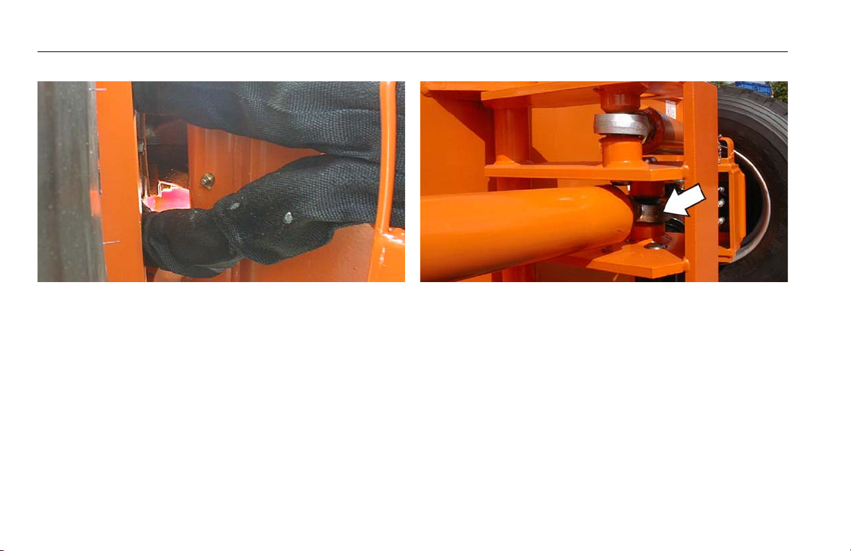
SECTION 6 - GENERAL SPECIFICATIONS & OPERATOR MAINTENANCE
2. Steer Spindles
Lube Point(s) - 4 Grease Fittings
Capacity - A/R
Lube - MPG
Interval - Every 3 months or 150 hrs of operation
3. Tie Rod Center Pivot Links
Lube Point(s) - 2 Grease Fittings
Capacity - A/R
Lube - MPG
Interval - Every 3 months or 150 hrs of operation
6-12 – JLG Lift – 3121213
Page 91

SECTION 6 - GENERAL SPECIFICATIONS & OPERATOR MAINTENANCE
4. Steer Cylinder Barrel Ends
Lube Point(s) - 2 Grease Fittings
Capacity - A/R
Lube - MPG
Interval - Every 3 months or 150 hrs of operation
5. Steer Cylinder Rod Ends
Lube Point(s) - 2 Grease Fittings
Capacity - A/R
Lube - MPG
Interval - Every 3 months or 150 hrs of operation
3121213 – JLG Lift – 6-13
Page 92

SECTION 6 - GENERAL SPECIFICATIONS & OPERATOR MAINTENANCE
6. Extending Axles
Lube Point(s) - N/A
Capacity - A/R
Lube - MPG
Interval - Every 3 months or 150 hrs of operation
Comments - Apply by brush
7. Swing Bearing Gear
Lube Point(s) - N/A
Capacity - A/R
Lube - MPG
Interval - Every 3 months or 150 hrs of operation
Comments - Apply by brush
6-14 – JLG Lift – 3121213
Page 93

SECTION 6 - GENERAL SPECIFICATIONS & OPERATOR MAINTENANCE
8. Lower Master Cylinder Barrel End
Lube Point(s) - 1 Grease Fitting
Capacity - A/R
Lube - MPG
Interval - Every 3 months or 150 hrs of operation
Comments - Remote Fitting on Left Rear of Turntable
9. Tower Boom Lift Cylinder Barrel End
Lube Point(s) - 1 Grease Fitting
Capacity - A/R
Lube - MPG
Interval - Every 3 months or 150 hrs of operation
Comments - Remote Fitting on Left Rear of Turntable
3121213 – JLG Lift – 6-15
Page 94

SECTION 6 - GENERAL SPECIFICATIONS & OPERATOR MAINTENANCE
10. Swing Bearing
Lube Point(s) - 2 Grease Fitting
Capacity - A/R
Lube - MPG
Interval - Every 3 months or 150 hrs of operation
Comments - Remote Fitting on Left Rear of Turntable
11. Lower Master Cylinder Rod End
Lube Point(s) - 1 Grease Fitting
Capacity - A/R
Lube - MPG
Interval - Every 3 months or 150 hrs of operation
Comments -
12. Platform Hinges
Lube Point(s) - 2 Grease Fittings
Capacity - A/R
Lube - MPG
Interval - Every 3 months or 150 hrs of operation
13. Platform Door Latch
Lube Point(s) - N/A
Capacity - A/R
Lube - EO
Interval - Every 3 months or 150 hrs of operation
6-16 – JLG Lift – 3121213
Page 95

SECTION 6 - GENERAL SPECIFICATIONS & OPERATOR MAINTENANCE
14. Platform Rotate Pivot/Rotator Worm Gear Lube Point(s) - 2 Grease Fittings on pivot; 1 Grease Fit-
ting on worm gear
Capacity - A/R
Lube - MPG
Interval - Every 3 months or 150 hrs of operation
15. Platform Level Links
Lube Point(s) - 3 Grease Fittings
Capacity - A/R
Lube - MPG
Interval - Every 3 months or 150 hrs of operation
3121213 – JLG Lift – 6-17
Page 96

SECTION 6 - GENERAL SPECIFICATIONS & OPERATOR MAINTENANCE
16. Level Cylinder Rod End
Lube Point(s) - 1 Grease Fitting
Capacity - A/R
Lube - MPG
Interval - Every 3 months or 150 hrs of operation
17. Level Cylinder Barrel End
Lube Point(s) - 1 Grease Fitting
Capacity - A/R
Lube - MPG
Interval - Every 3 months or 150 hrs of operation
18. Engine Crankcase
Lube Point(s) - Fill Cap/Drain Plug
Capacity - 10 quarts (9.5 L) w/o filter
Lube - EO
Comments - Check daily. Refer to Engine Manual for
Change interval.
6-18 – JLG Lift – 3121213
Page 97

SECTION 6 - GENERAL SPECIFICATIONS & OPERATOR MAINTENANCE
19. Engine Oil Filter
Lube Point(s) - N/A
Lube - EO
Comments - Refer to Engine Manual for Change interval.
20. Main Boom Chains
Lube Point(s) - N/A
Capacity - N/A
Lube - Chain Lube
Interval - Every 2 years or 1200 hours of operation.
21. Main Boom Extend Chain Sheave
Lube Point(s) - 1 Grease Fitting
Capacity - A/R
Lube - MPG
Interval - Every 3 months or 150 hrs of operation
Comments - Align access holes in mid and fly boom
22. Main Boom Lift Cylinder
Lube Point(s) - 1 Grease Fitting
Capacity - A/R
Lube - MPG
Interval - Every 3 months or 150 hrs of operation
3121213 – JLG Lift – 6-19
Page 98

SECTION 6 - GENERAL SPECIFICATIONS & OPERATOR MAINTENANCE
23. Main Boom Retract Chain Sheave
Lube Point(s) - 1 Grease Fitting
Capacity - A/R
Lube - MPG
Interval - Every 3 months or 150 hrs of operation
Comments - Align with access hole in base boom.
24. Main Boom Pivot Pin
Lube Point(s) - 1 Grease Fitting
Capacity - A/R
Lube - MPG
Interval - Every 3 months or 150 hrs of operation
25. Tower Boom Pivot Pin
Lube Point(s) - 1 Grease Fitting
Capacity - A/R
Lube - MPG
Interval - Every 3 months or 150 hrs of operation
6-20 – JLG Lift – 3121213
Page 99

SECTION 6 - GENERAL SPECIFICATIONS & OPERATOR MAINTENANCE
26. Level Links
Lube Point(s) - 3 Grease Fitting
Capacity - A/R
Lube - MPG
Interval - Every 3 months or 150 hrs of operation
Comments -
27. Upper Master Cylinder Rod End
Lube Point(s) - 1 Grease Fitting
Capacity - A/R
Lube - MPG
Interval - Every 3 months or 150 hrs of operation
Comments -
3121213 – JLG Lift – 6-21
Page 100

SECTION 6 - GENERAL SPECIFICATIONS & OPERATOR MAINTENANCE
28. Upper Master Cylinder Barrel End
Lube Point(s) - 1 Grease Fitting
Capacity - A/R
Lube - MPG
Interval - Every 3 months or 150 hrs of operation
Comments -
29. Tower Boom Lift Cylinder Rod End
Lube Point(s) - 1 Grease Fitting
Capacity - A/R
Lube - MPG
Interval - Every 3 months or 150 hrs of operation
Comments -
30. Hydraulic Oil
Lube Point(s) - Fill Cap/Drain Plug
Capacity - A/R
Lube - HO
Interval - Check daily. Change every 2 years or 1200
hours
Comments - On new machines, those recently overhauled, or after changing hydraulic oil, operate all systems a minimum of two complete cycles and recheck oil
level in reservoir.
31. Hydraulic Filter
Interval - Replace filter after first 50 hours of operation,
then every 6 months or 300 hours thereafter.
6-22 – JLG Lift – 3121213
 Loading...