


JMW9527CAS
JENN-AIR JMW9527CAS, JMW9530BAW, JMW9527BAB, JMW9530AAQ, JMW9530AAW Installation Instructions
...
NOTES
Z Do not block airintakeslots alongbottom ofoven.
INSTALLATION
1. Cut hole in cabinet to mount oven. Cutout in cabinet should
be level and straight. NOTE: There are no provisions to
level the unit after it is installed. An oven that is not level
could cause poor baking results.
2. Install plywood floor as shown above.
3. Attach unit to the cabinet with 4 No. 8² flat head screws
supplied inside of envelope containing these instructions.
Pre-drill holes in cabinet for attachment screws using 1/8²
drill. Oven mounting holes are provided in side trim.
4. See instructions “Electrical Connections” for electrical
hook-up.
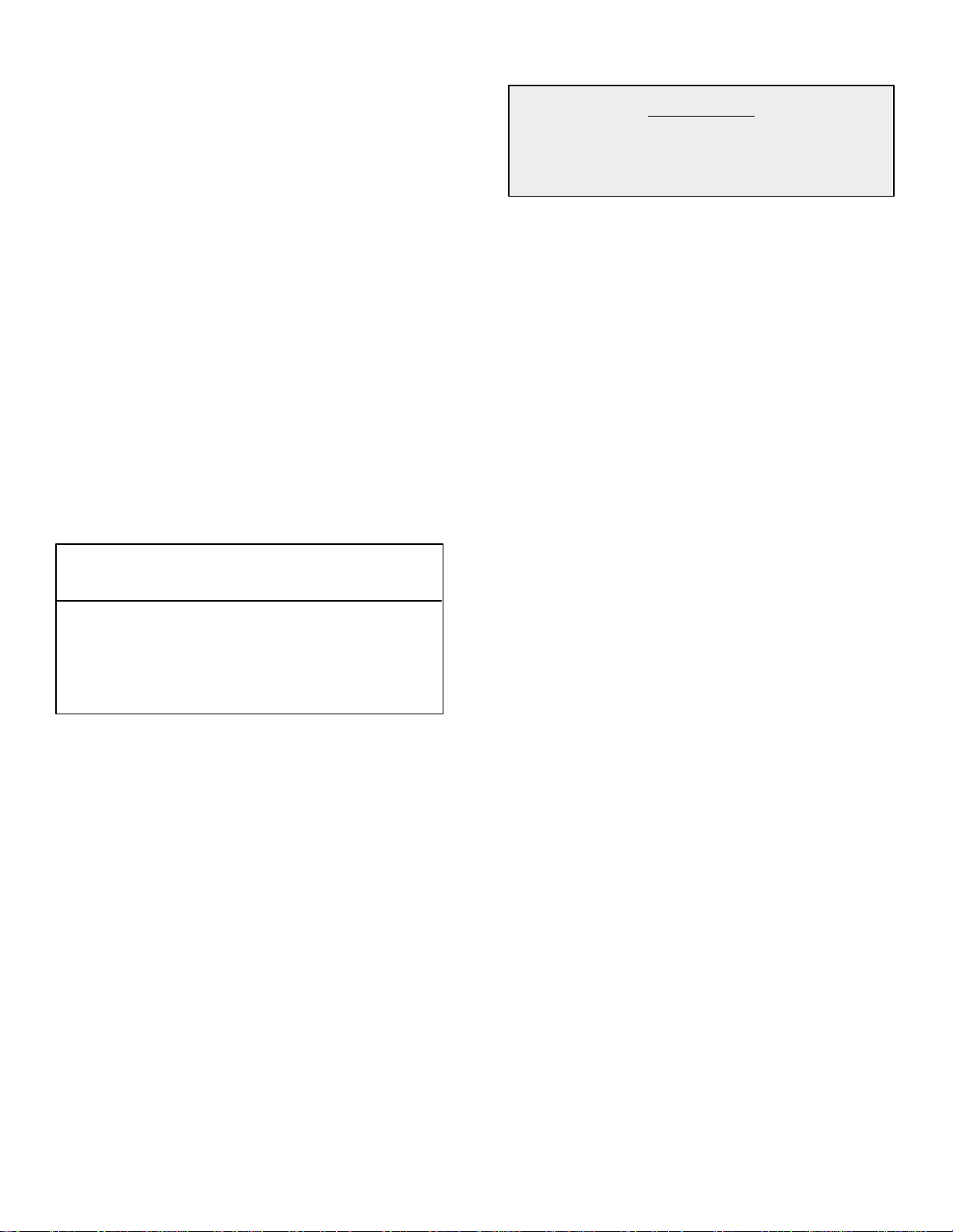
5. See figure 1 for lower trim installation.
6. See User’s Manual for operating instructions.
8101P420-60
(10-01-00)
Remove lower screws from hinge receptacle
plates. Align lower trim and reinstall screws.
CAUTION
For Europeanstyle cabinets(flush front) therequiredclearancefor operation ofthe ovendooris minimum
spacing of 7/8² between the cutout and the door, hinge or drawer of the cabinet.
Some built-in cabinets may not be wide enough, due to their construction, to allow this installation.
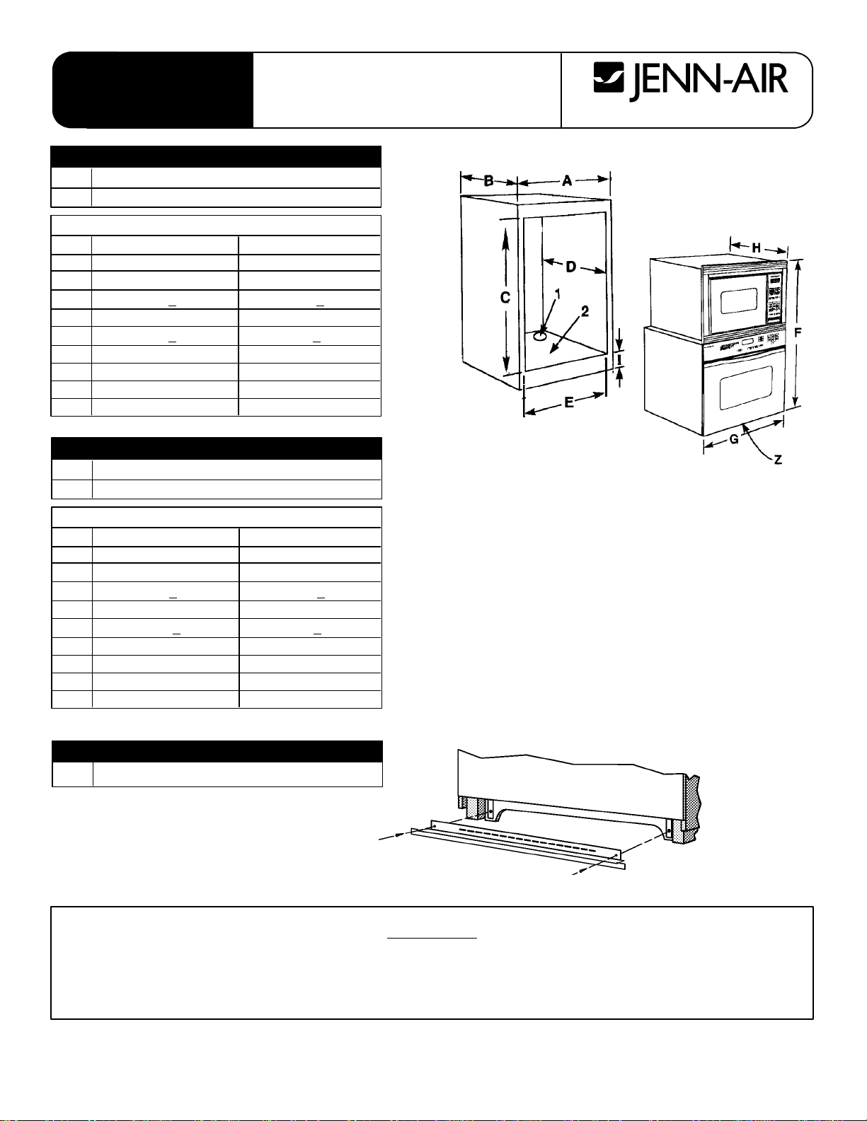
COMBINATION WALLOVEN CUTOUT
27² WALL OVEN DESCRIPTION
11-1/4² Dia. Conduit Access Hole*
25/8² Plywood Floor(MustSupport250 lbs.)
DIMENSIONS
in cm
A 27 MIN 68.58 MIN
B 24 MIN 60.96 MIN
C44-1/2+
1/16 113.03 + .16
D 23-1/2 MIN 59.69 MIN
E25-1/2+
1/16 64.77 + .16
F 44-15/16 114.14
G 26-3/4 67.95
H 24-7/16 62.07
I 4 to 20 10.2 to 50.8
30² WALL OVEN DESCRIPTION
11-1/4² Dia. Conduit Access Hole*
25/8² Plywood Floor(MustSupport250 lbs.)
DIMENSIONS
in cm
A 30 MIN 76.20 MIN
B 24 MIN 60.96 MIN
C44-1/2+
1/16 113.03 + .16
D 23-1/2 MIN 59.69 MIN
E 28-3/16 +
1/16 71.60 + .16
F 44-15/16 114.14
G 29-3/4 75.57
H 24-7/16 62.07
I 4 to 20 10.2 to 50.8
* Hole must be cut as close to corner of cabinet as possible.
INSTALLATION
INSTRUCTIONS
Built-In 27²
²²
² &30²
²²
² Electric
Combination Wall Ovens
403 WEST FOURTH STREET, NORTH D NEWTON, IA 50208
ELECTRICAL CONNECTIONS
Unit to be properly circuit protected and wired accordingto
local electrical code and National Electrical Code.
It is advisable that the electrical wiring and hookup be
accomplished by a competent electrician.
120/240 VAC or 120/208 VAC 60 Hz. See serial plate on
each unit for power requirements.
The neutral of the lower unit is grounded to the frame
through the green or solid grounding wire. (The green
and the white wires are twisted together at the
termination of the conduit.) If used on new branch-circuit
installations (1996 NEC), mobile homes, recreational
vehicles, or in an area where local codes prohibit
grounding through the neutral conductor, untwist or
disconnect the green wire and connect the green wire to
ground in accordance with local code. Connect the white
neutral to the service neutral. Connect all wires to the
branch circuit with approved connectors. Use copper or
aluminum wire. If aluminum wire is used, use connectors
recognized for joining aluminum to copper.
The chart below recommends the minimum circuit
protection and wire size if the appliance is the only unit
on the circuit.
WARNING
Improper installation of the grounding
circuit can result in a risk of electric
shock.
Consult a qualified electrician or serviceman if the
grounding instructions are not completely understood, or
if doubt exists as whether the appliance is properly
grounded.
SERVICE
Interrupt the source of electricity to the unit when
attempting to repair or service the oven. Failure to do
this could result in a dangerous or even fatal shock.
IMPORTANT - SAVE FOR LOCAL ELECTRICAL INSPECTOR’S USE
RECOMMENDED MINIMUM
K.W.RATING CIRCUIT PROTECTION WIRE SIZE
ON SERIAL PLATE IN AMPRES (AWG)
0-4.8 20 12
4.9 - 6.9 30 10
7.0 - 9.9 40 8
10.0 - 11.9 50 8
12.0 - 14.9 60 6
 Loading...