


JENNAIR JJW8630DDB, JJW8627DDW, JJW8627DDS, JJW8627DDQ, JJW8627DDB Installation Instructions
...INSTALLATION |
Built-In 27 & 30 |
|
INSTRUCTIONS |
Electric Wall Ovens |
403 WEST FOURTH STREET, NORTH |
NEWTON, IA 50208 |
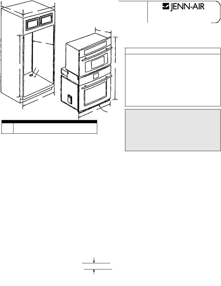
27 SINGLE WALL OVEN
11 1/4 Dia. Conduit Access Hole*
25/8 Plywood Floor (Must Support 200 lbs.)
DIMENSIONS
|
inches |
cm |
A |
27 MIN |
68.58 |
B |
24 MIN |
60.96 |
|
|
|
C |
29 1/16 + 1/16 |
73.82 |
|
|
|
D |
24 MIN |
60.96 |
E |
25 1/2 + 1/16 |
64.77 |
F |
29 1/2 |
74.93 |
G |
26 3/4 |
67.95 |
|
|
|
H |
25 7/16 |
64.61 |
I |
4 to 31 |
10.2 to 78.7 |
30 SINGLE WALL OVEN
11 1/4 Dia. Conduit Access Hole*
25/8 Plywood Floor (Must Support 200 lbs.)
DIMENSIONS
|
inches |
cm |
A |
30 MIN |
76.20 |
B |
24 MIN |
60.96 |
|
|
|
C |
29 1/16 + 1/16 |
73.82 |
|
|
|
D |
24 MIN |
60.96 |
E |
28 1/2 + 1/16 |
72.39 |
F |
29 1/2 |
74.93 |
G |
29 3/4 |
75.57 |
|
|
|
H |
25 7/16 |
64.61 |
I |
4 to 31 |
10.2 to 78.7 |
27 DOUBLE WALL OVEN
11 1/4 Dia. Conduit Access Hole*
25/8 Plywood Floor (Must Support 310 lbs.)
DIMENSIONS
|
inches |
cm |
A |
27 MIN |
68.58 |
|
|
|
B |
24 MIN |
60.96 |
|
|
|
C |
51 7/8 + 1/16 |
131.76 |
|
|
|
D |
24 MIN |
60.96 |
E |
25 1/2 + 1/16 |
64.77 |
F |
52 1/4 |
132.72 |
G |
26 3/4 |
67.95 |
H |
25 1/2 |
64.77 |
I |
4 to 10 |
10.2 to 25.4 |
NOTES
ZDo not blockair exhaust slots along bottom of oven.
YGas or electric cooktops may be installed over ovens. See cooktop installation instructions for cutout size.**
WElectrical connection for electric cooktop must in adjacent accessible location. Cook top and wall oven must be on separate 120/240 or 120/208 volt 60 Hz AC circuits.
CAUTION
For European style cabinets (flush front) the required clearance for operation of the oven door is minimum spacing of 7/8 between the cutout and the door, hinge or drawer of the cabinet.
Some built-in cabinets may not be wide enough, due to their construction, to allow this installation.
30 DOUBLE WALL OVEN
11 1/4 Dia. Conduit Access Hole*
25/8 Plywood Floor (Must Support 310 lbs.)
DIMENSIONS
|
inches |
cm |
A |
30 MIN |
76.20 |
|
|
|
B |
24 MIN |
60.96 |
|
|
|
C |
51 7/8 + 1/16 |
131.76 |
|
|
|
D |
24 MIN |
60.96 |
E |
28 1/2 + 1/16 |
72.39 |
F |
52 1/4 |
132.72 |
G |
29 3/4 |
75.57 |
H |
25 1/2 |
64.77 |
I |
4 to 10 |
10.2 to 25.4 |
30 WALL OVEN UNDER COUNTER
11 1/4 Dia. Conduit Access Hole*
2 5/8 Plywood Floor (Must Support 200 lbs.)
DIMENSIONS
|
inches |
cm |
A |
25 |
63.50 |
B |
24 MIN |
60.96 |
|
|
|
C |
29 1/16 + 1/16 |
73.82 |
|
|
|
D |
24 MIN |
60.96 |
E |
28 1/2 |
72.39 |
F |
29 1/2 |
74.93 |
G |
29 3/4 |
75.57 |
|
|
|
H |
25 7/16 |
64.61 |
I |
36 |
91.44 |
J |
1 1/2 |
3.81 |
|
|
|
30 WALL OVEN
|
|
inches |
cm |
K |
All JA Cooktops |
3 MAX |
7.62 MAX |
NOTE: |
* |
Hole must be cut as close to corner of cabinet as possible. |
|
** |
See dealer for approved cooktops. |
|
SINGLE WALL OVEN |
|
|
|
1 |
|
|
|
2 |
H |
|
|
|
|
|
|
D |
|
|
|
C |
|
F |
|
E |
|
|
|
I |
G |
Z |
|
|
|
|
|
Art #: 9220-025 |
|
|
B |
A |
|
|
|
|
|
|
|
DOUBLE WALL OVEN |
|
|
Art #: 9220-026
UNDER COUNTER WALL OVEN
See pages 5, 6 and 7 for detailed installation instructions.
J |
|
W |
Y |
A |
|
|
|
|
|
|
H |
|
|
|
|
|
|
|
|
|
|
|
|
1 |
2 |
|
F |
I |
|
|
D |
|
|
|
|
|
C |
|
|
|
|
|
|
B |
|
|
|
|
|
|
|
E |
G |
Z |
|
|
K |
|
Art #: 9220-027 |
|||
|
|
|
||||
|
|
|
|
|
|
|
8101P602-60
(11-03-00)
INSTALLATION |
Built-In 27 & 30 Electric |
|
INSTRUCTIONS |
Combination Wall Ovens |
403 WEST FOURTH STREET, NORTH |
NEWTON, IA 50208 |
|
27 WALL OVEN DESCRIPTION |
|
|
30 WALL OVEN DESCRIPTION |
1 |
1-1/4 Dia. Conduit Access Hole* |
|
1 |
1-1/4 Dia. Conduit Access Hole* |
2 |
5/8 Plywood Floor (Must Support 275 lbs.) |
|
2 |
5/8 Plywood Floor (Must Support 275 lbs.) |
DIMENSIONS
|
in |
cm |
A |
27 MIN |
68.58 MIN |
B |
24 MIN |
60.96 MIN |
C |
51-7/8 + 1/16 |
131.76 + .16 |
D |
24 MIN |
60.96 MIN |
E |
25-1/2 + 1/16 |
64.77 + .16 |
|
|
|
F |
52-15/16 |
134.46 |
|
|
|
G |
26-3/4 |
67.95 |
H |
25-7/16 |
64.61 |
I |
4 to 10 |
10.2 to 25.4 |
* Hole must be cut as close to corner of cabinet as possible.
NOTES
ZDo not block air exhaust slots along bottom of oven.
DIMENSIONS
|
in |
cm |
A |
30 MIN |
76.20 MIN |
B |
24 MIN |
60.96 MIN |
C |
51-7/8 + 1/16 |
131.76 + .16 |
D |
24 MIN |
60.96 MIN |
E |
28-1/2 + 1/16 |
72.39 + .16 |
|
|
|
F |
52-15/16 |
134.46 |
|
|
|
G |
29-3/4 |
75.57 |
H |
25-7/16 |
64.61 |
I |
4 to 10 |
10.2 to 25.4 |
CAUTION
For European style cabinets (flush front) the required clearance for operation of the oven door is minimum spacing of 7/8 between the cutout and the door, hinge or drawer of the cabinet.
Some built-in cabinets may not be wide enough, due to their construction, to allow this installation.
COMBINATION WALLOVEN CUTOUT
NOTE:
INSTALLED WALL OVEN OVERLAPS CUTOUT 15/16 (2.38 CM) AT THE TOP AND 1/8 (0.32 CM) AT THE BOTTOM.
THIS MUST BE TAKEN INTO CONSIDERATION WHEN LOCATING CUTOUT IF INSTALLED UNIT IS TO BE CENTERED IN THE CABINET.
B A
H
D
C |
1 |
F |
|
2 |
|
|
|
I E
Art #: 9220-028 |
G |
Z |
|
2
 WARNING
Improper installation of the grounding circuit can result in a risk of electric shock.
Consult a qualified electrician or serviceman if the grounding instructions are not completely understood, if doubt exists as whether the appliance is properly grounded.
CAUTION
For European style cabinets (flush front) the required clearance for operation of the oven door is minimum spacing of 7/8 between the cutout and the door, hinge or drawer of the cabinet.
Some built-in cabinets may not be wide enough, due to their construction, to allow this installation.
Installation
1.Cut hole in cabinet to mount oven. Cutout in cabinet should be level and straight.
NOTE: There are no provisions to level the unit after it is installed. An oven that is not level could cause poor baking results.
2.Install plywood floor as shown.
3.Remove oven door(s). See Oven Door Removal procedure.
4.Attach unit to the cabinet with four No. 8 x 1 screws supplied with unit inside of envelope containing these instructions. Pre-drill holes in cabinet for attachment screws using 1/8 drill. Oven mounting holes are provided in side trim.
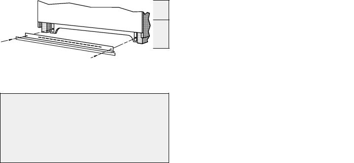
5.Install bottom trim.
6.Replace oven door(s). See Oven Door Replacement procedure.
7.See instructions at right for electrical hook-up.
8.See Use and Care Manual for operating instructions.
Installing Bottom Trim Piece
Remove
receptacle plates. Align lower trim and reinstall screws.
DO NOT INSTALL BOTTOM TRIM UNTIL UNIT IS ATTACHED TO THE CABINET.
Electrical Connections
Unit to be properly circuit protected and wired according to local electrical code and National Electrical Code.
It is advisable that the electrical wiring and hookup be accomplished by a competent electrician.
120/240 VAC or 120/208 VAC 60 Hz. See serial plate on front of unit for power requirements.
The neutral of this unit is grounded to the frame through the solid grounding wire. (The ground and the white wires are twisted together at the termination of the conduit.) If used on new branch-circuit installations (1996 NEC), mobile homes, recreational vehicles, or in an area where local codes prohibit grounding through the neutral conductor, untwist or disconnect the ground wire and connect to ground in accordance with local code. Connect the white neutral to the service neutral. Connect all wires to the branch circuit with approved connectors. Use copper or aluminum wire. If aluminum wire is used, use connectors recognized for joining aluminum to copper.
The chart below recommends the minimum circuit protection and wire size if the appliance is the only unit on the circuit.
K.W. RATING |
RECOMMENDED MINIMUM |
WIRE SIZE |
||
CIRCUIT PROTECTION |
||||
ON SERIAL PLATE |
IN AMPERS |
(AWG) |
||
0 |
- |
4.8 |
20 |
12 |
4.9 |
- |
6.9 |
30 |
10 |
7.0 |
- |
9.9 |
40 |
8 |
10.0 |
- |
11.9 |
50 |
8 |
12.0 |
- 14.9 |
60 |
6 |
|
|
|
|
|
|
Service
Interrupt the source of electricity to the unit when attempting to repair or service the oven. Failure to do this could result in a dangerous or even fatal shock.
IMPORTANT - SAVE FOR LOCAL ELECTRICAL INSPECTOR’S USE
3
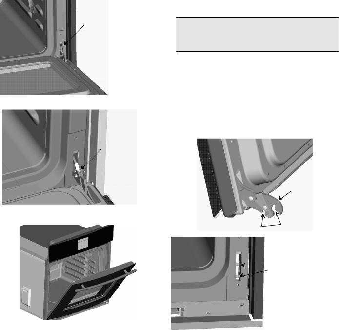
Oven Door Removal
For ease of installation, remove oven door(s) before placing unit into cutout. This will reduce the weight of the unit by about 35 pounds per door. Remove oven door(s) as follows:
SOpen oven door to the “Full Open” position (see Figure 1).
SRotate hinge locking lever DOWN, to unlock hinge from the unit (see Figure 2).
SClose oven door to the “Removal” position (until it stops; see Figure 3).
SGrasp the door firmly on each side and lift the door straight up and off the unit.
NOTE: The oven door is heavy. Be sure you have a firm grip before lifting the oven door off the unit.
Do not lift the door by the handle!
Hinge Locking Lever
(Locked Position)
Figure 1
Hinge Locking Lever
(Unlocked Position)
Figure 2
Figure 3
Oven Door Replacement
Replace oven door(s) after placing unit into cutout. Replace oven door(s) as follows:
SGrasp oven door firmly on each side, hold oven door at approximately a 30° angle and align oven door hinge arm (see Figure 4) with hinge receiver on unit (see Figure 5).
SInsert oven door hinge arm into hinge receiver until the hinge arm slots (see Figure 4) align with horizontal pins on the hinge receiver (see Figure 5) and place hinge arm onto the hinge receiver.
SOnce the hinge arms are resting on the hinge receiver pins (see Figure 3) open oven door slowly to the “Full Open” position (see Figure 2).
SRotate hinge locking lever UP to the locked position to secure the oven door to the unit (see Figure 1).
NOTE: Make sure that hinge locking lever is rotated fully UP to the locked position as shown (see Figure 1) before closing oven door.
CAUTION
Door will not close all the way and could fall off when opened if the hinge locking levers are not rotated fully UP to the locked position.
If hinge locking lever will not rotate fully UP to the locked position as shown (see Figure 1) then the hinge arm is not properly seated on the receiver. Rotate the hinge locking lever DOWN to the unlocked position (see Figure 2) and remove oven door as outlined in the Oven Door Removal procedure. Then replace the oven door as outlined in the Oven Door Replacement procedure, making sure that the hinge arm slots are fully seated on the horizontal pins in the hinge receiver.
SOnce the hinge locking lever is rotated fully UP to the locked position (see Figure 1) close the oven door.
Hinge Arm
Figure 4
Hinge Arm Slots
 Hinge Receiver
 Horizontal Pins
Figure 5
4
INSTALLATION |
30 Under Counter |
|
INSTRUCTIONS |
Wall Oven |
403 WEST FOURTH STREET, NORTH |
NEWTON, IA 50208 |
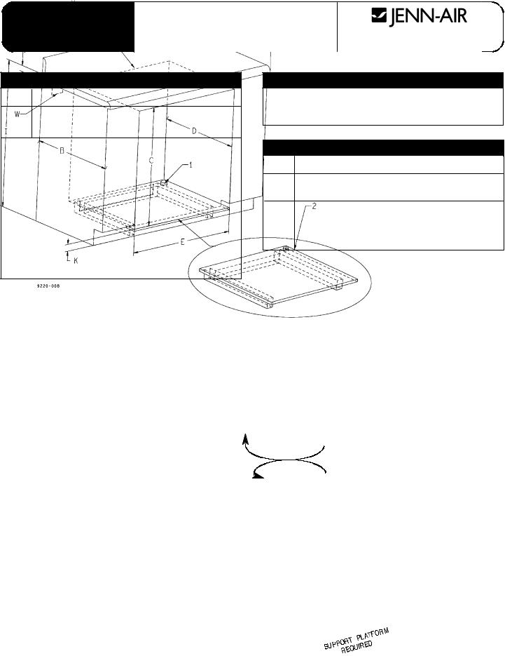
30 WALL OVEN UNDER COUNTER
11-1/4 Dia. Conduit Access Hole*
25/8 Plywood Floor (Must Support 200 lbs.)
See next page for Support Platform Construction
|
DIMENSIONS |
|
|
|
|
|
|
|
inches |
|
cm |
|
|
|
|
A |
25 |
|
63.50 |
|
|
|
|
B |
24 MIN |
|
60.96 |
|
|
|
|
C |
29-1/16 + 1/16 |
|
73.82 |
|
|
|
|
D |
24 MIN |
|
60.96 |
|
|
|
|
E |
28-1/2 |
|
72.39 |
|
|
|
|
I |
36 |
|
91.44 |
|
|
|
|
J |
1-1/2 |
|
3.81 |
30 WALL OVEN
|
inches |
cm |
|
|
|
K |
3 MAX |
7.62 MAX |
|
|
|
NOTES
ZDo not block air exhaust slots along bottom of oven.
YGas or electric cooktops may be installed over ovens.** See cooktop installation instructions for cutout size.
WElectrical connection for electric cooktop must in adjacent accessible location. Cook top and wall oven must be on separate 120/240 or 120/208 volt
60 Hz AC circuits.
NOTE: |
* |
Hole must be cut as close to corner of cabinet |
|
|
as possible. |
|
** |
See dealer for approved cooktops. |
SIDE AND/OR TOP FILLERS
MAY BE NECESSARY IF UNIT
IS POSITIONED BETWEEN
EXISTING CABINETS. BE
SURE THEY ARE ATTACHED
SECURELY, SINCE THEY WILL
ANCHOR THE OVEN IN THE
CABINET.
5
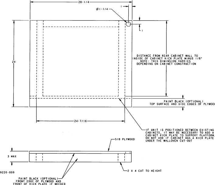
Support Platform
30 Under Counter Wall Oven
6

COOKTOP SHOWN FOR REFERENCE ONLY.
SEE COOKTOP INSTALLATION INSTRUCTIONS FOR CUTOUT SIZE.
MIN
9220-010
30 Under Counter Wall Oven
with Cooktop
7
 Loading...