


JENNAIR® 30", 36", AND 48" (76.2 CM, 91.4 CM, AND 121.9 CM) COMMERCIAL STYLE WALLMOUNT CANOPY RANGE HOOD
HOTTE DE CUISINIÈRE JENNAIR® DE STYLE COMMERCIAL POUR POUR MONTAGE MURAL DE 30", 36" ET 48" (76,2 CM, 91,4 CM ET 121,9 CM)
Installation Instructions and Use & Care Guide
For questions about features, operation/performance, parts, accessories, or service in the U.S.A., call:
1-800-JENNAIR (1-800-536-6247) or visit our website at www.jennair.com.
In Canada, call: 1-800-JENNAIR (1-800-536-6247), or visit our website at www.jennair.ca.
Instructions d’installation et Guide d’utilisation et d’entretien
Au Canada, pour assistance, installation ou service, composez le 1-800-JENNAIR (1-800-536-6247) ou visitez notre site web à www.jennair.ca.
Table of Contents/Table des matières...................................... |
2 |
IMPORTANT: READ AND SAVE THESE INSTRUCTIONS.
FOR RESIDENTIAL USE ONLY.
IMPORTANT : LIRE ET CONSERVER CES INSTRUCTIONS.
POUR UTILISATION RÉSIDENTIELLE UNIQUEMENT.
LI3UND/W11280191B

TABLE OF CONTENTS |
|
RANGE HOOD SAFETY.................................................................. |
3 |
INSTALLATION REQUIREMENTS................................................. |
5 |
Tools and Parts............................................................................. |
5 |
Location Requirements................................................................. |
5 |
Venting Requirements................................................................... |
7 |
Electrical Requirements................................................................ |
8 |
INSTALLATION INSTRUCTIONS................................................... |
8 |
Prepare Location........................................................................... |
8 |
Install Range Hood....................................................................... |
9 |
Install Range Hood Blower Motor................................................ |
9 |
Make Electrical Connection........................................................ |
10 |
Complete Installation and Check Operation.............................. |
11 |
RANGE HOOD USE...................................................................... |
12 |
Range Hood Controls................................................................. |
12 |
RANGE HOOD CARE.................................................................... |
13 |
Range Hood Lamps.................................................................... |
13 |
Cleaning...................................................................................... |
13 |
WIRING DIAGRAM........................................................................ |
14 |
ASSISTANCE OR SERVICE.......................................................... |
15 |
In the U.S.A................................................................................. |
15 |
In Canada.................................................................................... |
15 |
Accessories................................................................................. |
15 |
TABLE DES MATIÈRES |
|
SÉCURITÉ DE LA HOTTE DE CUISINIÈRE................................ |
16 |
EXIGENCES D’INSTALLATION.................................................... |
18 |
Outillage et pièces...................................................................... |
18 |
Exigences d’emplacement......................................................... |
18 |
Exigences concernant l’évacuation............................................ |
20 |
Spécifications électriques........................................................... |
21 |
INSTRUCTIONS D’INSTALLATION............................................. |
21 |
Préparation de l’emplacement................................................... |
21 |
Installation de la hotte................................................................. |
22 |
Installation du moteur du ventilateur de la hotte........................ |
22 |
Raccordement électrique........................................................... |
23 |
Achever l’installation et vérifier le fonctionnement..................... |
24 |
UTILISATION DE LA HOTTE........................................................ |
25 |
Commandes de la hotte de cuisinière........................................ |
25 |
ENTRETIEN DE LA HOTTE DE CUISINIÈRE.............................. |
26 |
Lampes de la hotte de cuisinière................................................ |
26 |
Nettoyage.................................................................................... |
27 |
SCHÉMAS DE CÂBLAGE............................................................. |
28 |
ASSISTANCE OU SERVICE.......................................................... |
29 |
Au Canada.................................................................................. |
29 |
Accessoires................................................................................. |
29 |
2
RANGE HOOD SAFETY
Your safety and the safety of others are very important.
many important safety messages in this manual and on your appliance. Always read and obey all safety
safety alert symbol.
alerts you to potential hazards that can kill or hurt you and others.
messages will follow the safety alert symbol and either the word “DANGER” or “WARNING.” mean:
 DANGER
  WARNING
You can be killed or seriously injured if you don't immediately follow instructions.
You can be killed or seriously injured if you don't follow instructions.
All safety messages will tell you what the potential hazard is, tell you how to reduce the chance of injury, and tell you what can happen if the instructions are not followed.
3

IMPORTANT SAFETY INSTRUCTIONS
 Ducted fans must always be vented to the outdoors.


 For General Ventilating Use Only. Do Not Use
To Exhaust Hazardous Or Explosive Materials And Vapors.


 To Reduce The Risk Of Fire Or Electric
Shock, Do Not Use This Fan With Any Solid-State Speed
Control Device.
 This appliance is not intended for use by people (including children) whose physical, sensory or mental capacities are different or impaired or who lack the necessary experience or knowledge/expertise to do so, unless such persons are supervised or are trained to operate the appliance by a person who accepts responsibility for their safety.
READ AND SAVE THESE INSTRUCTIONS
4
INSTALLATION REQUIREMENTS
Tools and Parts
Gather the required tools and parts before starting installation. Read and follow the instructions provided with any tools listed here.
Tools needed
■■ Level
■■ Drill
■■ 1¼" (3 cm) drill bit
■■ 1/8" (3 mm) drill bit if installing into wood and a 5/16" (8 mm) drill bit if installing optional backsplash kit.
■■ Pencil
■■ Wire stripper or utility knife ■■ Tape measure or ruler
■■ Pliers
■■ Caulking gun and weatherproof caulking compound ■■ Vent clamps
■■ Jigsaw or keyhole saw ■■ Flat-blade screwdriver ■■ Metal snips
■■ Phillips screwdriver ■■ Scissors
Parts needed
■■ Home power supply cable
■■ 1 - 1/2" (12.7 mm) UL listed or CSA approved strain relief ■■ 3 UL listed wire connectors
■■ 1 wall or roof cap ■■ Metal vent system
Parts supplied
Remove parts from packages. Check that all parts are included. 2 metal grease filters for 30" (76.2 cm) models
3 metal grease filters for 36" (91.4 cm) models
4 metal grease filters for 48" (121.9 cm) models Damper
Hood canopy with blower and halogen lamps installed.
1 - 10" (25.4 cm) square to 10" (25.4 cm) round duct transition.
2 - 175 W infrared heat lamps Wood support
Grease collectors
4 - 6 x 80 mm mounting screws
4 - 3.5 x 9.5 mm screws
6 - 4.2 x 19 mm screws
■■ 5 - M6 x 16 mm screws ■■ 5 - D6.4 x 11 mm washers ■■ 2 - D5.3 x 20 mm washers
■■ 2 - 10 x 50 mm wall anchors ■■ T20® TORX®†adapter
Location Requirements
IMPORTANT: Observe all governing codes and ordinances. Have a qualified technician install the range hood. It is the installer’s responsibility to comply with installation clearances specified on the model/serial/rating plate. The model/serial/ rating plate is located inside the range hood on the rear wall of the range hood.
Canopy range hood location should be away from strong draft areas, such as windows, doors and strong heating vents.
Cabinet opening dimensions that are shown must be used. Given dimensions provide minimum clearance.
The canopy range hood is factory set for venting through the roof or through the wall.
All openings in ceiling and wall where canopy range hood will be installed must be sealed.
For Mobile Home Installations
The installation of this range hood must conform to the Manufactured Home Construction Safety Standards, Title 24 CFR, Part 328 (formerly the Federal Standard for Mobile Home Construction and Safety, Title 24, HUD, Part 280) or when such standard is not applicable, the standard for Manufactured Home Installation 1982 (Manufactured Home Sites, Communities and Setups) ANSI A225.1/NFPA 501A, or latest edition, or with local codes.
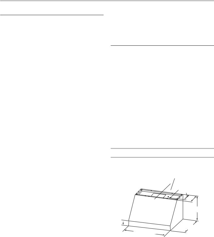
Product Dimensions
Front view
18¹⁄ " (45.9 cm) for 48" (121.9 cm) Hood 12¹⁄ " (30.6 cm) for 36" (91.4 cm) Hood 9¹⁄ " (23.0 cm) for 30" (76.2 cm) Hood
CL

 6¹⁄ " (16.5 cm)
 12" (30.5 cm)
18" (45.7 cm)
2¹⁄ "
(5.7 cm) 
25" (63.5 cm)
30" (76.2 cm) 36" (91.4 cm)
48" (121.9 cm)
†®TORX and T20 are registered trademarks of Acument Intellectual Properties, LLC
5
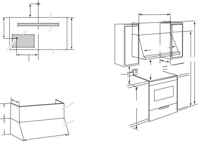
Back view |
|
|
|
|
|
9 ⁄ " |
|
A |
|
|
(25.0 cm) |
|
|
|
8³⁄ " |
D |
|
|
|
(21.3 cm) |
CL |
|
18" |
|
|
|
B |
||
|
|
(45.7 cm) |
||
|
|
|
||
E |
|
|
|
|
|
|
|
C |
|
18¹³⁄ " (47.8 cm) for 48" (121.9 cm) Hood |
|
|||
12¹³⁄ " (32.5 cm) for 36" (91.4 cm) Hood |
|
|||
9¹³⁄ " (24.9 cm) for 30" (76.2 cm) Hood |
|
|||
A. Top of hood |
C. Bottom of hood |
|
||
B. Wood support |
D. Home wiring system |
|
||
|
|
E. Knockout into terminal box |
||
Optional Full-Width Duct Cover Installations
12" |
|
(30.5 cm) |
A |
|
12" (30.5 cm)
B
18" (45.7 cm)
A.Optional full-width duct cover
B.Range hood
Installation Dimensions
30" (76.2 cm), 36" (91.4 cm), or 48" (121.9 cm)
cabinet opening width
(If installed between cabinets)
Vent cover (if used |
) |
|
|
Min. cabinet |
|
|
opening width |
|
|
y |
|
|
Canop |
|
|
|
A B |
|
X |
13" (33.0 cm) |
|
Bottom of canopy |
|
18" (45.7 cm) min. |
to cooking surface |
|
|
|
|
clearance upper |
|
|
cabinet to countertop |
|
|
36" (91.4 cm) countertop height
A. 84" (213.4 cm) minimum for |
B. 96" (243.8 cm) minimum for |
installations with canopy only. |
installations with optional |
|
duct cover. |
IMPORTANT:
Minimum distance “X”: 30" (76.2 cm) Suggested maximum distance “X”: 36" (91.4 cm)
6
Venting Requirements
■■ Vent system must terminate to the outdoors.
■■ Do not terminate the vent system in an attic or other enclosed area.
■■ Do not use 4" (10.2 cm) laundry-type wall caps.
■■ Use metal vent only. Rigid metal vent is recommended. Plastic or metal foil vent is not recommended.
■■ The length of vent system and number of elbows should be kept to a minimum to provide efficient performance.
For the most efficient and quiet operation:
■■ Use no more than three 90° elbows.
■■ Make sure there is a minimum of 24" (61.0 cm) of straight vent between the elbows if more than 1 elbow is used.
■■ Do not install 2 elbows together.
■■ Use clamps to seal all joints in the vent system.
■■ The vent system must have a damper. If the roof or wall cap has a damper, do not use the damper supplied with the range hood.
■■ Use caulking to seal exterior wall or roof opening around the cap.
■■ The size of the vent should be uniform.
Cold weather installations
An additional back draft damper should be installed to minimize backward cold air flow and a thermal break should be installed to minimize conduction of outside temperatures as part of the vent system. The damper should be on the cold air side of the thermal break.
The break should be as close as possible to where the vent system enters the heated portion of the house.
Makeup air
Local building codes may require the use of makeup air systems when using ventilation systems greater than specified CFM of air movement. The specified CFM varies from locale to locale. Consult your HVAC professional for specific requirements in your area.
Venting Methods
A 10" (25.4 cm) round vent system is needed for installation
(not included). The hood exhaust opening is 10" (25.4 cm) round.
NOTE: Flexible vent is not recommended. Flexible vent creates back pressure and air turbulence that greatly reduce performance.
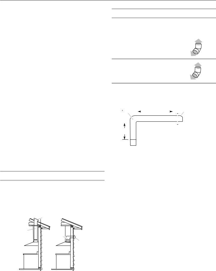
Vent system can terminate either through the roof or wall.
Roof Venting |
Wall Venting |
A
B* 
B*
A
Calculating Vent System Length
To calculate the length of the system you need, add the equivalent feet (meters) for each vent piece used in the system.
Vent Piece |
Equivalent Length |
45° elbow |
2.5 ft (0.8 m) |
90° elbow |
5.0 ft (1.5 m) |
The maximum equivalent vent lengths are: 10" (25.4 cm) round vents - 60 ft (18.3 m)
Example vent system
90 elbow |
|
|
|
|
|
|
Wall cap |
||||
|
|
6 ft (1.8 m) |
|
|
|||||||
|
|
|
|
|
|
||||||
|
|
|
|
|
|
|
|
|
|
|
|
|
|
|
|
|
|
|
|
|
|
|
|
|
|
|
|
|
|
|
|
|
|
|
|
|
|
|
|
|
|
|
|
|
|
|
|
|
|
|
|
|
|
|
|
|
|
|
|
2 ft
(0.6 m)
The following example falls within the maximum recommended vent length.
1 |
- 90° elbow |
= 5.0 ft (1.5 m) |
1 |
- wall cap |
= 0.0 ft (0.0 m) |
8 ft (2.4 m) straight |
= 8.0 ft (2.4 m) |
|
|
|
|
Length of system |
= 13.0 ft (3.9 m) |
|
|
|
|
A. Roof cap |
A.Wall cap |
B. 10" (25.4 cm) round vent |
B. 10" (25.4 cm) round vent |
7
Electrical Requirements
Observe all governing codes and ordinances.
Ensure that the electrical installation is adequate and in conformance with National Electrical Code, ANSI/NFPA 70 (latest edition), or CSA Standards C22.1-94, Canadian Electrical Code, Part 1 and C22.2 No. 0-M91 (latest edition) and all local codes and ordinances.
If codes permit and a separate ground wire is used, it is recommended that a qualified electrician determine that the ground path is adequate.
A copy of the above code standards can be obtained from: National Fire Protection Association
1 Batterymarch Park
Quincy, MA 02169-7471
CSA International
8501 East Pleasant Valley Road
Cleveland, OH 44131-5575
■■ A 120 V, 60 Hz. AC only, 15 A, fused electrical circuit is required.
■■ If the house has aluminum wiring, follow the procedure below:
Connect the aluminum wiring using special connectors and/or tools designed and UL listed for joining copper to aluminum.
Follow the electrical connector manufacturer’s recommended procedure. Aluminum/copper connection must conform with local codes and industry accepted wiring practices.
■■ Wire sizes and connections must conform with the rating of the appliance as specified on the model/serial/rating plate. The model/serial/rating plate is located behind the left filter on the rear wall of the range hood.
■■ Wire sizes must conform to the requirements of the National Electrical Code, ANSI/NFPA 70 (latest edition), or CSA Standards C22. 1-94, Canadian Electrical Code, Part 1 and C22.2 No. 0-M91 (latest edition) and all local codes and ordinances.
INSTALLATION INSTRUCTIONS
Prepare Location
■■ It is recommended that the vent system be installed before hood is installed.
■■ If you are installing the optional backsplash with shelves for heat lamps, follow the instructions included with that product.
■■ Before making cutouts, make sure there is proper clearance within the ceiling or wall for exhaust vent.
■■ Check that all installation parts have been removed from the shipping carton.
1.Disconnect power.
2.Determine which venting method to use: roof or wall exhaust.
3.Select a flat surface for assembling the range hood. Place covering over that surface.
 WARNING
Excessive Weight Hazard
Use two or more people to move and install range hood.
Failure to do so can result in back or other injury.
4.Using 2 or more people, lift range hood onto covered surface.
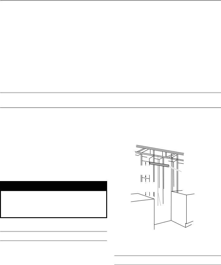
Range Hood Mounting Screws Installation
The hood is attached to the wall with the wood support that is attached to the back of the hood.
1.Determine and mark the centerline on the wall where the canopy range hood will be installed.
2.Select a mounting height between a minimum of 30" (76.2 cm) and a suggested maximum of 36" (91.4 cm) above the cooking surface and the bottom of the range hood, and mark a horizontal reference line on the wall.
3.Remove the wood support from the back of the range hood by loosening the 2 screws from the inside. Locate and level the top of the wood support 153/8" (39.1 cm) above the marked horizontal line and centered on the vertical centerline. Using 2 - 4 of the 6 x 80 mm screws, install wood support so that it is screwed into at least 2 vertical studs.
15³⁄" |
|
(39 cm) |
A |
30" (76.2 cm) to 36" (91.4 cm)
B
A.Wood support
B.Centerline
NOTE: The screws provided for mounting this hood must be fastened into solid wood. Do not fasten into sheet rock only.
Optional Duct Cover Installation
1.Attach the full-width duct cover to the top of the range hood with the screws provided with duct covers. The duct cover must be attached to the top of the range hood before mounting the range hood to the wall. For information on ordering the optional duct cover, see the “Accessories” section.
8
Complete Preparation
1.Determine and make all necessary cuts in the wall for the vent system. Install the vent system before installing the range hood. See the “Venting Requirements” section.
2.Determine the location where the power supply cable will be run through the wall.
3.Drill a 1¼" (3.2 cm) hole at this location.
4.Pull enough power supply cable through the wall to allow for easy connection to the terminal box.
5.Install the 10" (25.4 cm) square x 10" (25.4 cm) round vent transition with damper to top of the range hood using
4 - 3.5 x 9.5 mm screws.
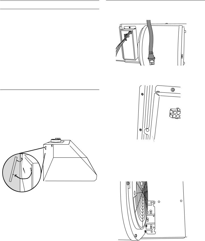
6.Remove terminal box cover and set aside.
7.Remove knockout from the back of the vent hood and install a UL listed or CSA approved 1/2" strain relief. See “Make Electrical Connection” section.
8.Place the range hood near its mounting position and run the power supply cable through the strain relief into terminal box (enough to make connection).
9.Tighten the strain relief screws.
Install Range Hood
The hood attaches to the wall by the 2 mounting screws in the wood support mounted to the wall in “Range Hood Mounting Screws Installation” in the “Prepare Location” section.
1.Using 2 or more people, hang the range hood on the wall by placing the slotted holes in the range hood back over the 2 screws mounted to the wood support mounted to the wall.
NOTE: If your installation uses the optional duct cover, the vent system needs to be connected to the hood and the duct cover mounted to the top of the range hood before tightening the mounting screws. See steps 5 and 6.
 →
→
 →
→ 
2.Push the range hood up into the narrow slots, align the bottom of the hood to the horizontal line, level the hood, and tighten the 2 mounting screws.
3.Mark 2 lower mounting hole locations. Drill 1/8" pilot holes if the holes are located in wood. If holes are not located in wood, remove the hood and drill two 3/8" pilot holes and insert 10 x 50 mm wall anchors. Remount the hood, level, and tighten the upper screws. Install 2 - 6 x 80 mm screws into the lower mounting anchors and tighten.
4.Install 4 - 4.2 x 19 mm screws through the back of the hood into the wood support and tighten.
5.Connect vent system to hood. Seal all joints with clamps.
6.If your installation uses the optional duct cover, mount it to the top of the range hood following the instructions supplied
with the duct cover.
Install Range Hood Blower Motor
1.Install the range hood blower motor assembly inside the hood canopy with the wiring to the left.
 A
A
A.Blower motor
2.Slide the left mounting plate flange under the bracket.
A 
B
A.Bracket
B.Mounting plate flange
3.Push the right end of the mounting plate up and snap into spring tab.
NOTE: The spring tab should be outside of the slot in the mounting plate.
 A
A
A. Spring tab
9
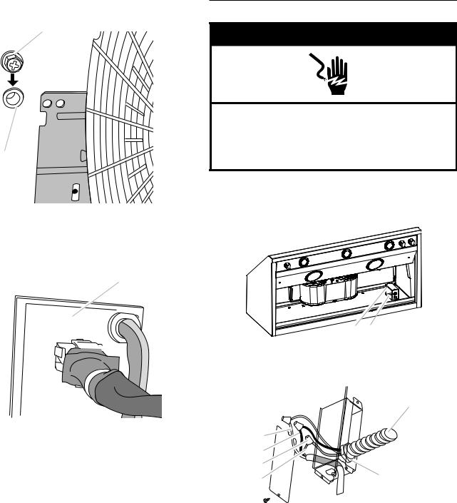
4. Align mounting holes and install 5 - 6 x 16 mm screws.
A
B


A. Screw B.Mounting hole
5.Attach power cord connector to connector on wire box on blower motor mounting plate.
A
B 

C 
A.Blower motor mounting plate
B.Wire box connector
C.Power cord
Make Electrical Connection
 WARNING
Electrical Shock Hazard Disconnect power before servicing.
Replace all parts and panels before operating.
Failure to do so can result in death or electrical shock.
1.Disconnect power.
2.Locate junction box inside of the range hood.
A B
A.Terminal box cover
B.Knockout in canopy back into terminal box
E
A |
|
B |
|
C |
|
D |
F |
A.White wires
B.Black wires
C.UL listed wire connectors
D.Green, bare or yellow/green wires
E.Home power supply
F.UL listed or CSA approved 1/2" strain relief
10
 Loading...