


JS42PPDBDA
Installation Instructions
Tool Requirements:
Tape measure
Level
Stud finder
Drill with various bits
Socket set
Utility knife
Magnetic extended screwdriver
Phillips screwdriver
Torx Bit
Cardboard, carpet remnant or other
protective material for flooring
Steel Hanger Strap
Installation Checklist:
INSTALLER
Doors
[] Handles are solidly attached to doors.
[] Doors seal completely to refrigerator cabinet.
[] Assure correct door handle alignment. Frame models.
[] Assure door seals are not pinched.
[] Do not drive screws / sharp objects into the doors.
Leveling
[] L Brackets are secure to 2x4 wood block.
[] Stabilizing legs are against floor. Cabinet is secure.
[] Toe kickplate is properly attached to refrigerator
and aligned with floor.
Icemaker
[] Water supply to refrigerator is turned on and lines flushed.
[] Water leaks are not present at connection between household
water supply and refrigerator.
[] lcemaker arm is down for ice production.
[] PuriClean ® Ice and Water Filtration System is installed correctly,
if applicable.
[] Purge water from the fountain on dispenser models.
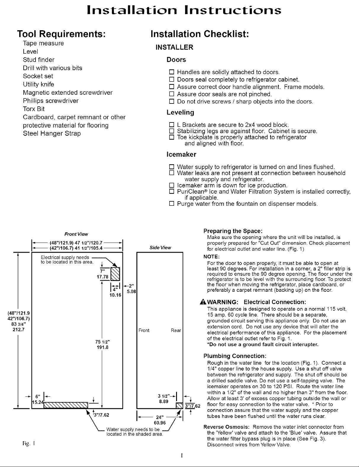
(48"/121.9
42"/106.7'
83 3/4"
212.7
Front View
IX (48"/121.9) 47 1/2"/120.7
(42"/106.7) 41 112"1105.4
Electrical supply needs _.
to be located in this area. ,L ""_
Fig. I
17.78 _
9_--2 '1
5.08
10,1_
75 1/2"
191.8
Water supply )eels to _'49_
located in the shaded area.
Side View
Front Rear
3 1/2"--_ I
Preparing the Space:
Make sure the opening where the unit will be installed, is
properly prepared for "Cut Out" dimension. Check placement
for electrical outlet and water line. (Fig. 1)
NOTE:
For the door to open properly, it must be able to open at
least 90 degrees. For installation in a corner, a 2" filler strip is
required to ensure the 90 degree opening. The floor under the
refrigerator is to be level with the surrounding floor. To protect
the floor when moving the refrigerator, place cardboard, or
preferably a carpet remnant (backing up) on the floor.
_WARNING: Electrical Connection:
This appliance is designed to operate on a normal 115 volt,
15 amp, 60 cycle line. There should be a separate,
grounded circuit serving this appliance only. Do not use an
extension cord. Do not use any device that will alter the
electrical performance of this appliance. For the placement
of the electrical outlet refer to Fig. 1.
*Do not use a ground fault circuit interupter.
Plumbing Connection:
Rough in the water line for the location (Fig. 1). Connect a
1/4" copper line to the house supply. Use a shut off valve
between the refrigerator and supply. The shut off should be
a drilled saddle valve. Do not use a self-tapping valve. The
icemaker operates on 30 to 120 PSI. Route the water line
within a 1/2" of the wall and no higher than 3" from the floor.
Allow at least 3' of excess copper tubing outside the wall or
3'-'_'_.62
floor for easy connection to the water valve. * Prior to
connection assure that the water supply and the copper
t
tubes have been flushed until the water runs clear.
Reverse Osmosis: Remove the water inlet connector from
the 'Yellow' valve and attach to the 'Blue' valve. Assure that
the water filter bypass plug is in place (See Fig. 3).
Disconnect wires from Yellow Valve.
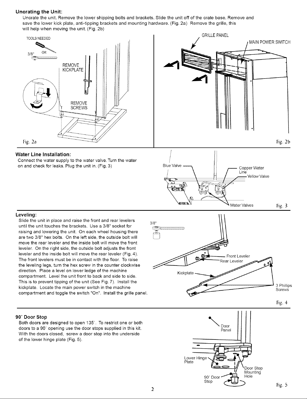
Uncrating the Unit:
Uncrate the unit. Remove the lower shipping bolts and brackets. Slide the unit off of the crate base. Remove and
save the lower kick plate, anti-tipping brackets and mounting hardware. (Fig. 2a) Remove the grille, this
will help when moving the unit. (Fig. 2b)
TOOLS NEEDED
3/8" _
REMOVE
KICKPLATE_
REMOVE
lr SCREWS
GRILLEPANEL
SWITCH
Fig. 2a
Water Line Installation:
Connect the water supply to the water valve. Turn the water
on and check for leaks. Plug the unit in. (Fig. 3)
Leveling:
Slide the unit in place and raise the front and rear levelers
until the unit touches the brackets. Use a 3/8" socket for
raising and lowering the unit. On each wheel housing there
are two 3/8" hex bolts. On the left side, the outside bolt will
move the rear leveler and the inside bolt will move the front
leveler. On the right side, the outside bolt adjusts the front
leveler and the inside bolt will move the rear leveler (Fig. 4).
The front levelers must be in contact with the floor. To raise
the leveling legs, turn the hex screw in the counter clockwise
direction. Place a level on lower ledge of the machine
compartment. Level the unit front to back and side to side.
This is to prevent tipping of the unit (See Fig. 7). Install the
kickplate. Locate the main power switch in the machine
compartment and toggle the switch "On". Install the grille panel.
Fig.2b
Biu!Valve _ 1 C°P_I:wa:lve
:ves
Fig. 3
Front Leveler
90 ° Door Stop
Both doors are designed to open 135 °. To restrict one or both
doors to a 90 opening use the door stops supplied in this kit.
With the doors closed, screw a door stop into the underside
of the lower hinge plate (Fig. 5).
%,,pOOe ' ])
Lower Hinge
Plate _...._/f_
____/ _Door Stop
9toDO°r ____H°Ie
Fig.4
.!/ _4ounting
Fig. 5
 Loading...