


JXD7030YS

30" (76.2 CM) AND 36" (91.4 CM)
RETRACTABLE (POP-UP) DOWNDRAFT
VENT SYSTEM
SYSTÈME DE VENTILATION RÉTRACTABLE
(CLAPET) DE 30" (76,2 CM) ET 36" (91,4 CM) -
ASPIRATION PAR LE BAS
Installation Instructions and Use & Care Guide
For questions about features, operation/performance, parts, accessories, or service in the U.S.A., call:
1-800-JENNAIR (1-800-536-6247), or visit our website at www.jennair.com.
In Canada, call: 1-800-JENNAIR (1-800-536-6247), or visit our website at www.jennair.ca.
Instructions d’installation et Guide d’utilisation et d’entretien
Pour des questions à propos des caractéristiques, du fonctionnement/rendement, des pièces, accessoires ou dépannage, composer le :
Au Canada, composer le : 1-800-JENNAIR (1-800-536-6247) ou visitez notre site web à www.jennair.ca.
IMPORTANT: READ AND SAVE THESE INSTRUCTIONS.
FOR RESIDENTIAL USE ONLY.
IMPORTANT : LIRE ET CONSERVER CES INSTRUCTIONS.
POUR UTILISATION RÉSIDENTIELLE UNIQUEMENT.
LI3ZVC/W10342490F
1-800-JENNAIR (1-800-536-6247) ou visitez notre site web à www.jennair.com.

TABLE OF CONTENTS TABLE DES MATIÈRES
VENT SYSTEM SAFETY.................................................................3
INSTALLATION REQUIREMENTS .................................................5
Tools and Parts .............................................................................5
Location Requirements ................................................................5
Electrical Requirements ...............................................................8
Venting Requirements ..................................................................8
INSTALLATION INSTRUCTIONS ...................................................9
Venting Methods ..........................................................................9
Install Vent System .....................................................................10
Rear Mounting — Blower Motor ................................................12
Complete Installation .................................................................14
Make Electrical Connections .....................................................16
Check Operation ........................................................................16
VENT SYSTEM USE .....................................................................17
Operating Downdraft Vent .........................................................17
VENT SYSTEM CARE ..................................................................17
Surface of Downdraft Vent .........................................................17
Filters ..........................................................................................17
TROUBLESHOOTING ..................................................................18
WIRING DIAGRAM .......................................................................19
ASSISTANCE OR SERVICE .........................................................20
In the U.S.A. ...............................................................................20
In Canada ...................................................................................20
Accessories ................................................................................20
WARRANTY ..................................................................................21
SÉCURITÉ DU SYSTÈME DE VENTILATION ............................. 22
EXIGENCES D'INSTALLATION ...................................................24
Outils et pièces ...........................................................................24
Exigences d’emplacement .........................................................24
Spécifications électriques ..........................................................27
Exigences concernant l'évacuation ...........................................27
INSTRUCTIONS D'INSTALLATION .............................................28
Méthodes d’évacuation .............................................................28
Installation du conduit d’évacuation ..........................................29
Montage du ventilateur à l'arrière ..............................................31
Achever l’installation ..................................................................33
Raccordements électriques .......................................................35
Contrôle du fonctionnement ......................................................35
UTILISATION DU SYSTÈME D’EXTRACTION ........................... 36
Utilisation du système d’extraction par le bas ..........................36
ENTRETIEN DU SYSTÈME D’ÉVACUATION .............................37
Surface du système d’extraction par le bas ..............................37
Filtres ..........................................................................................37
DÉPANNAGE .................................................................................38
SCHÉMA DE CÂBLAGE ...............................................................39
ASSISTANCE OU SERVICE .........................................................40
Aux É.-U. ....................................................................................40
Au Canada ..................................................................................40
Accessoires ................................................................................40
GARANTIE .....................................................................................41
2
VENT SYSTEM SAFETY
Your safety and the safety of others are very important.
We have provided many important safety messages in this manual and on your appliance. Always read and obey all safety
messages.
This is the safety alert symbol.
This symbol alerts you to potential hazards that can kill or hurt you and others.
All safety messages will follow the safety alert symbol and either the word “DANGER” or “WARNING.”
These words mean:
You can be killed or seriously injured if you don't immediately
DANGER
WARNING
All safety messages will tell you what the potential hazard is, tell you how to reduce the chance of injury, and tell you what can
happen if the instructions are not followed.
State of California Proposition 65 Warnings:
WARNING: This product contains one or more chemicals known to the State of California to cause cancer.
WARNING: This product contains one or more chemicals known to the State of California to cause birth defects or other
reproductive harm.
follow instructions.
You
can be killed or seriously injured if you don't
instructions.
follow
3
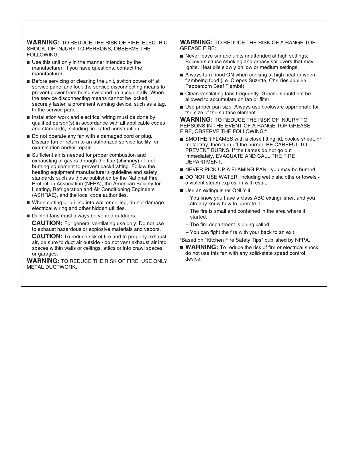
IMPORTANT SAFETY INSTRUCTIONS
READ AND SAVE THESE INSTRUCTIONS
4

INSTALLATION REQUIREMENTS
Tools and Parts
Gather the required tools and parts before starting installation.
Read and follow the instructions provided with any tools
listed here.
Tools Needed
■ Jigsaw or keyhole saw
■ Drill
1
■
/8" (3 mm) drill bit for pilot holes
■ Pencil
■ Tape measure or ruler
■ Flat-blade screwdriver
■ Phillips screwdriver
3
■
/8" (9.5 mm) nut driver
■ Level
■ Pliers
■ Metal snips
■ Wire stripper or utility knife
■ Caulking gun and weatherproof caulking compound
Parts Supplied
■ Top trim – stainless
■ End caps (2)
■ Lower support legs (2)
■ Undercounter mounting brackets (2)
■ 4 x 8 mm screws (16)
■ 3.5 x 9.5 mm screws (3)
1
■ 3
/4" x 10" (8.3 cm x 25.4 cm) rectangular damper
3
■ 4
/4" (12.0 cm) motor box
■ ¼" (6.4 mm) deep cover
■ Flat vent cover plate
■ 6" (15.2 cm) diameter vent transition with damper
Parts Needed
■ UL listed or CSA approved ½" (12.7 mm) conduit connector
■ Wall or roof cap with damper to match vent system
■ Vent system
■ Home power supply cable
■ UL listed wire connectors (3)
■ Vent clamps/duct tape as required
Location Requirements
NOTE: Downdraft vent is installed directly behind the cooktop.
Install the downdraft vent first, and then install the cooktop.
IMPORTANT: Observe all governing codes and ordinances.
■ Have a qualified technician install the downdraft vent. It
is the installer’s responsibility to comply with installation
clearances specified on the model/serial/rating plate. The
model/serial/rating plate is located on the front of the
downdraft vent above the terminal box cover.
■ Downdraft vent location should be away from strong draft
areas, such as windows, doors, and strong heating vents
or fans.
■ Cabinet opening dimensions that are shown must be used.
Given dimensions provide minimum clearance.
■ Consult the cooktop manufacturer installation instructions
before making any cutouts.
Check that the downdraft vent and cooktop location will
clear the cabinet walls, backsplash, and rear wall studs
inside the cabinet.
Check for the minimum distance between the front edge
of the countertop and the front edge of the cooktop. The
minimum horizontal distance between the overhead cabinets
is the same as the width of the installed downdraft vent.
■ All openings in ceiling and wall where the downdraft vent
will be installed must be sealed.
■ Grounded electrical outlet is required. See “Electrical
Requirements” section.
■ When installing the downdraft vent, the cabinet drawer
will need to be removed and the drawer front installed
permanently to the cabinet.
Cabinet Construction:
Downdraft vent is designed for use in a cabinet with a depth of
24" (61 cm). Some installations require a countertop deeper than
25" (63.5 cm). See the “Countertop Cutout Dimensions” section.
The maximum depth of the overhead cabinet is 13" (33 cm).
Overhead cabinets installed at either side of the downdraft vent
must be 18" (45.7 cm) above the cooking surface.
For Mobile Home Installations
The installation of this downdraft vent must conform to the
Manufactured Home Construction Safety Standards, Title 24
CFR, Part 328 (formerly the Federal Standard for Mobile Home
Construction and Safety, title 24, HUD, Part 280) or when such
standard is not applicable, the standard for Manufactured Home
Installation 1982 (Manufactured Home Sites, Communities
and Setups) ANSI A225.1/NFPA 501A, or latest edition, or with
local codes.
5
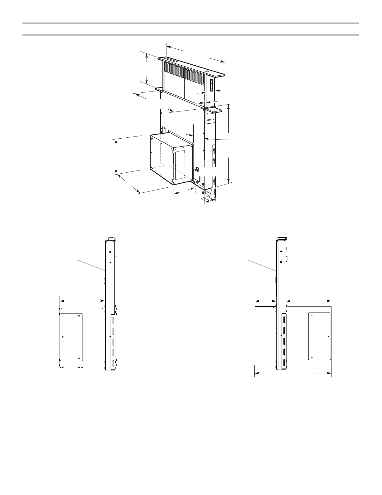
Product Dimensions
Reversed Blower
Range Hood
13¹⁄₂" (34.3 cm)
retractable
vent height
27" (68.6 cm) for 30" (76.2 cm) vent
33" (83.8 cm) for 36" (91.4 cm) vent
13¹⁄₈" (33.4 cm)
16¹⁄₂" (42.0 cm)
Top trim widths:
30" (76.2 cm)
36" (91.4 cm)
10"
(25.4 cm)
³⁄₄"
(1.9 cm)
2¹⁄₈" (5.4 cm)
1¹⁄₂" (3.8 cm)
³⁄₈" (0.95 cm)
5¹⁄₄"(13.3 cm)
for 30" (76.2 cm) vent
8¹⁄₄" (21.0 cm)
for 36" (91.4 cm) vent
28¹⁄₂"
(72.4 cm)
As-Received Blower
Front of
10" (25.4 cm)
Front of
Range Hood
4³⁄₄"
(12 cm)
(25.4 cm)
16¹⁵⁄₁₆" (43 cm)
10"
6
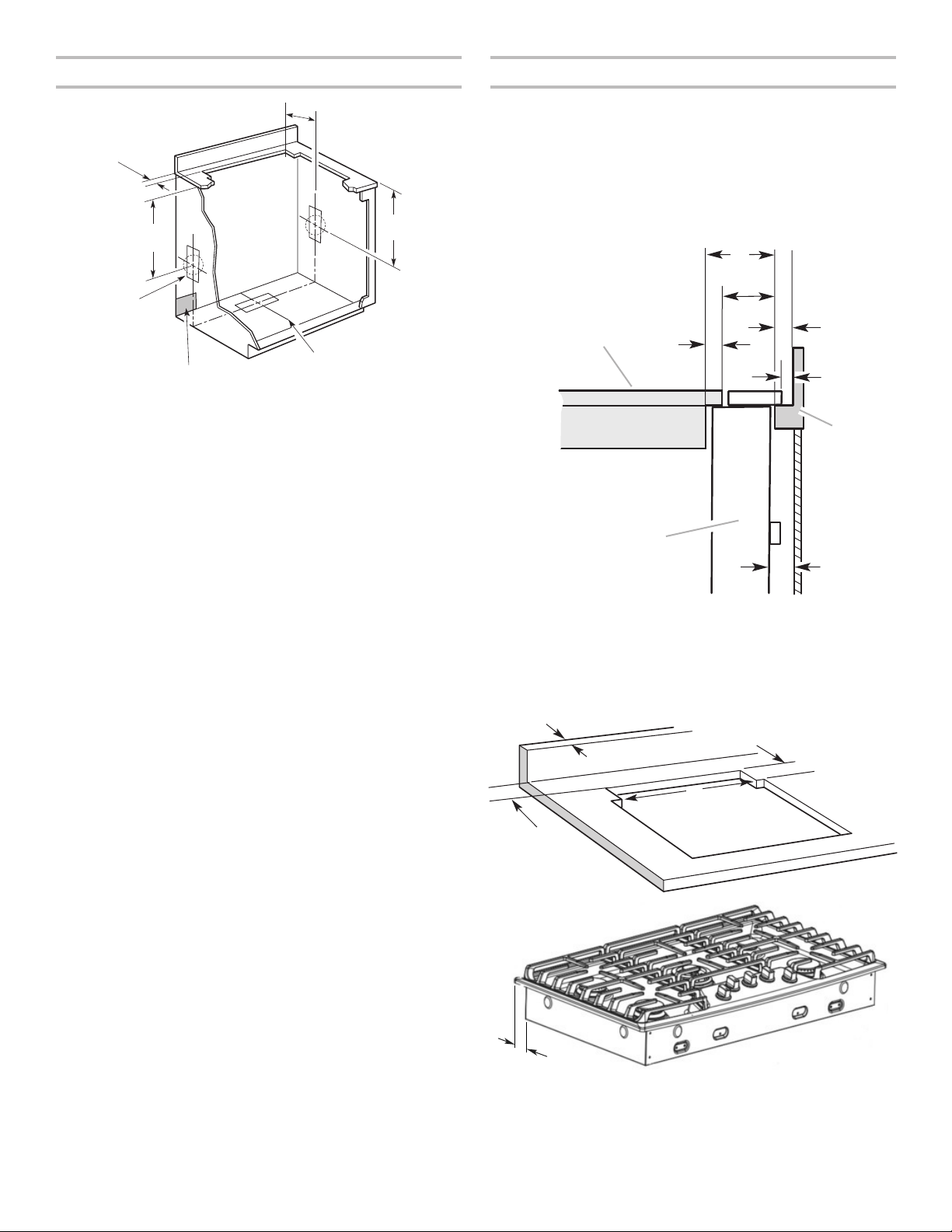
Cabinet Dimensions
H
D
B
Countertop Cutout Dimensions
10" (25.4 cm)
A = ¹⁄₂" (12.7 mm)
minimum
21⁵⁄₁₆"
21⁵⁄₁₆"
(54.1 cm)
Cutouts are
for 3¹⁄₄" x 10"
(8.3 cm x 25.4 cm)
rectangular or 6"
(15.2 cm) round
vent system.
Locate power
supply junction
box at lower
left-hand
rear corner
of the cabinet.
Centerline of cooktop cutout
(54.1 cm)
NOTES:
■ See cooktop manufacturer’s instructions for cooktop cutout
depth and width.
■ Use dimensions for vent system cutout location that applies
to your installation.
■ Interior-mounted blower systems connect with 3
1
/4" x 10"
(8.3 cm x 25.4 cm) rectangular or 6" (15.2 cm) round vent
system. The cutout locations for this vent system will
depend on your specific installation.
IMPORTANT: Countertops with a bull-nosed front edge are not
recommended for these installations.
Some models require a countertop deeper than 25" (63.5 cm);
see the following illustrations.
To avoid mistakes, it is recommended that the cooktop and vent
cutouts be drawn on the countertop before making any cutouts.
See the Installation Instructions that came with your cooktop
for complete cutout dimensions, location dimensions, and
installation details.
E
F
B
C
G
A
I
A. Downdraft vent
B. Cooktop
C. Measurement of cooktop rear
overhang
D. D = Measurement of cooktop rear
overhang (C) + 113/16" (46.2 mm) (E)
E. 113/16" (46.2 mm)
F. ½" (12.7 mm) minimum
G. ¼" (6.4 mm) minimum
H. Countertop and backsplash
I. ½" (12.7 mm) minimum
D
C
A
A. ½" (12.7 mm) minimum to
B.
E
backsplash or rear wall
3
/4" (19.1 mm) maximum
backsplash depth
C. 271/2" (69.9 cm) on 30" (76.2 cm)
models
331/2" (85.9 cm) on 36" (91.4 cm)
models
D. D = E + 1
E. Cooktop rear overhang
13
/16" (46.2 mm)
7

Electrical Requirements
Observe all governing codes and ordinances.
Ensure that the electrical installation is adequate and in
conformance with National Electrical Code, ANSI/NFPA 70 (latest
edition) or CSA Standards C22.1-94, Canadian Electrical Code,
Part 1 and C22.2 No. 0-M91 (latest edition) and all local codes
and ordinances.
If codes permit and a separate ground wire is used, it is
recommended that a qualified electrician determine that
the ground path is adequate.
A copy of the above code standards can be obtained from:
National Fire Protection Association
1 Batterymarch Park
Quincy, MA 02169-7471
CSA International
8501 East Pleasant Valley Road
Cleveland, OH 44131-5575
■ A 120-volt, 60 Hz., AC-only, 15-amp, fused electrical
circuit is required.
■ If the house has aluminum wiring, follow the procedure
below:
1. Connect a section of solid copper wire to the pigtail leads.
2. Connect the aluminum wiring to the added section
of copper wire using special connectors and/or tools
designed and UL listed for joining copper to aluminum.
Follow the electrical connector manufacturer's recommended
procedure. Aluminum/copper connection must conform with
local codes and industry accepted wiring practices.
■ Wire sizes and connections must conform with the rating of
the appliance as specified on the model/serial/rating plate.
The model/serial/rating plate is located on the front of the
downdraft vent above the wiring box cover.
■ Wire sizes must conform to the requirements of the National
Electrical Code, ANSI/NFPA 70 (latest edition) or CSA
Standards C22. 1-94, Canadian Electrical Code, Part 1 and
C22.2 No. 0-M91 (latest edition) and all local codes and
ordinances.
Venting Requirements
IMPORTANT: Make sure there is proper clearance within the wall
or floor before making exhaust vent cutouts.
■ Use heavy (rigid) metal vent.
■ Venting system must terminate to the outside.
■ Do not terminate the vent system in an attic or other
enclosed area.
■ Do not use 4" (10.2 cm) laundry-type wall caps.
■ Do not install 2 elbows together.
■ Do not use plastic or metal foil vent.
■ The length of vent system and number of elbows should
be kept to a minimum to provide efficient performance.
■ Use no more than three 90° elbows.
■ Make sure there is a minimum of 24" (61 cm) of straight vent
between the elbows if more than one elbow is used.
■ Use clamps or duct tape to seal all joints in the vent system.
■ Use caulking tape to seal the exterior wall or floor opening
around cap.
■ Do not cut joist or stud. If vent cutout falls over a joist
or stud, a supporting frame must be constructed.
Flexible metal vent is not recommended. If it is used, calculate
each foot of flexible vent as 2 ft (0.6 m) of rigid metal vent.
Flexible elbows count twice as much as standard elbows.
Recommended vent system length:
For either interior-mounted or exterior-mounted blower
installations, the vent system length should not exceed the
maximum lengths listed in the “Maximum Length of Vent
System” chart. See “Calculating Vent System Length” in the
“Venting Methods” section in the Installation Instructions.
Cold Weather Installations
An additional backdraft damper should be installed to minimize
backward cold airflow and a thermal break should be installed
to minimize conduction of outside temperatures as part of the
vent system. The damper should be on the cold air side of the
thermal break.
The break should be as close as possible to where the vent
system enters the heated portion of the house.
Makeup Air
Local building codes may require the use of makeup air systems
when using ventilation systems greater than specified CFM of
air movement. The specified CFM varies from locale to locale.
Consult your HVAC professional for specific requirements in
your area.
8
INSTALLATION INSTRUCTIONS
A
B
C
B
E
G
J
B
E
F
J
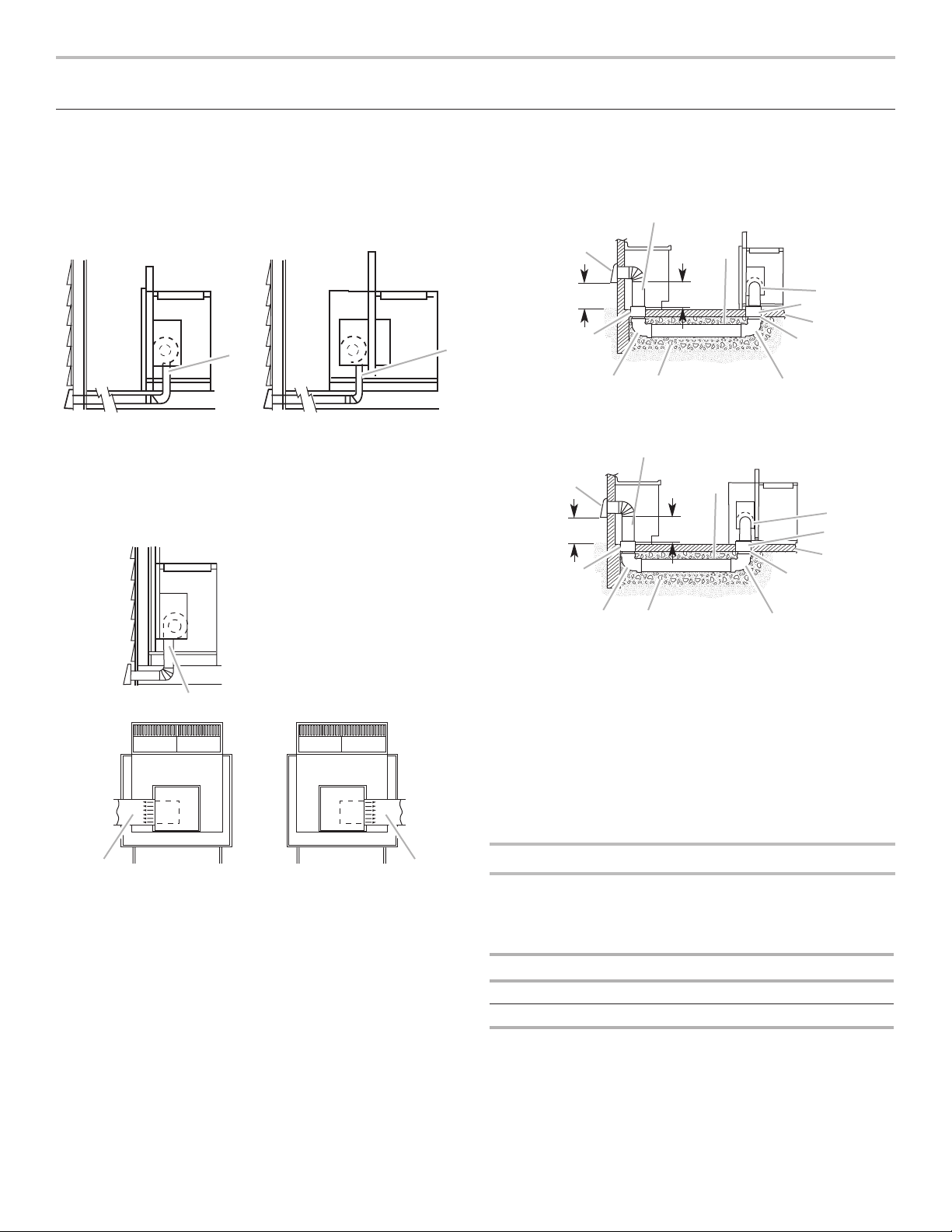
Venting Methods
Determine which venting method is best for your application.
Vent system can terminate either through the wall or floor.
Island Location
Front-Mounted Blower
Motor (Standard)
Rear-Mounted Blower Motor
Island Location — Vent System Installed Under
a Concrete Slab Using PVC Sewer Pipe
Front-Mounted Blower Motor (Standard)
A
D
A
A. Down vent
NOTE: For island locations, a front- or rear-mounted blower
motor can also be mounted for right or left venting if needed for
your application. Most island applications would still require the
venting to be directed down through the floor.
Built-In Cabinet Location
A
M
L
K
C
F
H
I
Rear-Mounted Blower Motor
A
M
L
K
A. Wall cap
B. 6" (15.2 cm) round metal vent
C. 16" (40.6 cm) maximum
D. 6" (15.2 cm) round PVC sewer pipe
E. 6" (15.2 cm) round metal vent transition with damper (supplied)
F. 6" (15.2 cm) round PVC coupling
G. Concrete slab
H. 6" (15.2 cm) round PVC sewer pipe
I. 6" (15.2 cm) round 90° PVC sewer pipe elbow
J. Tightly pack gravel or sand completely around pipe.
K. 6" (15.2 cm) round 90° PVC sewer pipe elbow
L. 6" (15.2 cm) round PVC coupling
M. 12" (30.5 cm) minimum
C
D
H
I
G
Calculating Vent System Length
A. Down vent
B. Left vent
C. Right vent
3¼" x 10" (8.3 cm x 25.4 cm) rectangular vent is required from
the blower motor box. It can be transitioned to 6" (15.2 cm)
round vent if needed.
Maximum Length of Vent System
Vent Length
6" (15.2 cm) round 35 ft (8.9 m)
31/4" x 10" (8.3 cm x 25.4 cm) 35 ft (8.9 m)
9
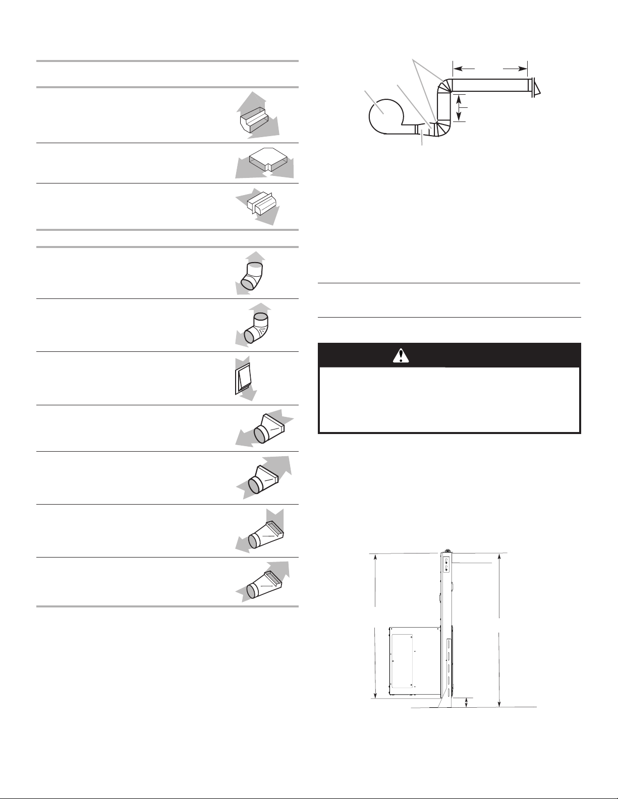
To calculate the length of the system you need, add the
A
C
D
Cabinet floor
Top of countertop
(73 cm)
equivalent feet (meters) for each vent piece used in the system.
Vent Piece
31/4" x 10" (8.3 cm x 25.4 cm)
90° elbow
31/4" x 10" (8.3 cm x 25.4 cm)
Rectangular
5.0 ft
(1.5 m)
Example Vent System
B
6 ft
(1.8 m)
2 ft (0.6 m)
31/4" x 10" (8.3 cm x 25.4 cm)
flat elbow
31/4" x 10" (8.3 cm x 25.4 cm)
wall cap
12.0 ft
(3.7 m)
0.0 ft
(0.0 m)
Vent Piece 6" (15.2 cm) Round
45° elbow 2.5 ft
(0.8 m)
90° elbow 5.0 ft
(1.5 m)
6" (15.2 cm) wall cap 0.0 ft
(0.0 m)
31/4" x 10" (8.3 cm x 25.4 cm)
to 6" (15.2 cm) transition
4.5 ft
(1.4 m)
A. Blower motor
B. Transition
C. 90° elbows
D. Backdraft damper
The following example falls within the maximum vent length
of 35 ft (8.9 m).
2 - 90° elbow = 10.0 ft (3 m)
1 - wall cap = 0.0 ft (0.0 m)
8 ft (2.4 m) straight = 8.0 ft (2.4 m)
Transition = 4.5 ft (1.4 m)
Length of 6" (15.2 cm) or 31/4" x 10"
= 22.5 ft (6.8 m)
(8.3 cm x 25.4 cm) system
Install Vent System
WARNING
Excessive Weight Hazard
Use two or more people to move and install
downdraft vent.
Failure to do so can result in back or other injury.
6" (15.2 cm) to 31/4" x 10"
(8.3 cm x 25.4 cm) transition
31/4" x 10" (8.3 cm x 25.4 cm)
to 6" (15.2 cm) 90° elbow
transition
6" (15.2 cm) to 31/4" x 10"
(8.3 cm x 25.4 cm) 90° elbow
transition
1 ft
(0.3 m)
5.0 ft
(1.5 m)
5.0 ft
(1.5 m)
1. Place cardboard or similar material on top of a flat surface
where you can easily assemble the downdraft vent system.
2. Remove parts packages, downdraft vent, and blower box
from the carton.
3. Remove all shipping materials, tape, and film from the
downdraft vent and blower box.
4. Measure distance “X” from the cabinet floor to the top of the
countertop. Subtract 281/2" (72.4 cm) from distance “X” to
determine dimension “Y” (X - 281/2" = Y).
Downdraft vent
28¹⁄₂"
“X”
“Y”
10
5. Attach the support legs to the side of the vent box with
A
B
“Y”
C
D
G
4 - 4 x 8 mm screws in each support leg. Adjust to dimension
“Y” from the bottom of the vent box to the bottom of the
support legs. Tighten screws.
C
Dim.
A. Motor box
B. Support leg
C. 4 x 8 mm screws (4)
Determine Which Vent Direction Is Best for
Your Installation
When installed in a cabinet, vent system can exhaust through
the bottom, left, or right of the cabinet.
IMPORTANT: When using the 6" (15.2 cm) vent transition
(supplied) for 6" round venting, only left or right venting is
recommended.
Bottom Venting:
NOTE: If installing the vent damper in the down position, a wall
or roof cap with a damper at the exit end of the vent system
is required.
■ Downdraft vent is shipped with blower in down-venting
position, so no modification is required.
■ If rear mounting of the blower motor is not required, go
to the “Complete Installation” section.
■ To mount the blower motor to the rear side of the vent box,
go to the “Rear Mounting — Blower Motor” section.
Left or Right Venting:
1. Using 2 or more people, place the downdraft vent system
on its back.
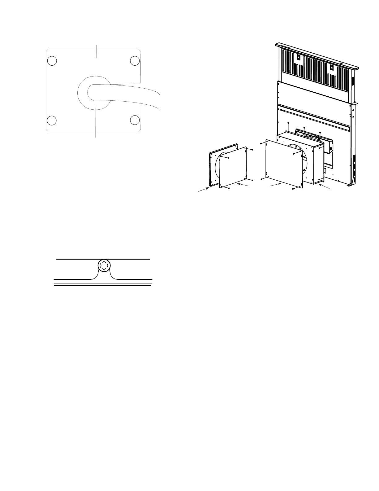
2. Remove the 4 screws from the cover plate mounted to the
face of the motor box and set them aside.
A
B
F
E
A. Cover plate
B. Cover plate screws (4)
C. Cover plate keyhole slot
shoulder screws (4)
3. Slide the cover plate up and slip it over the keyhole slot
shoulder screws. Set the cover aside.
4. Remove 4 screws from the bottom of the motor box that
hold the motor assembly to the motor box.
NOTE: Disconnect the electrical wiring connection from
motor if needed.
5. Remove 3 screws and the vent cover plate from the left
or right side of the motor box for the venting direction to
be used.
6. Rotate the blower motor assembly 90° to the left or right side
to the chosen venting direction and secure to the blower box
with motor mounting screws previously removed. Do not
twist or bind the wires.
7. Install the vent cover plate over the rectangular opening in the
bottom of the motor box and secure with vent cover screws.
NOTE: Reinstall the electrical wiring connection to motor
if removed.
8. Reinstall the cover plate to the face of the motor box and
secure with 4 cover plate screws previously removed.
9. For mounting the blower motor to the back of the vent
box, go to the “Rear Mounting — Blower Motor” section.
Otherwise, go to the “Complete Installation” section.
D. Motor mounting screws (4)
E. Vent cover plate
F. Motor box
G. Vent cover screws (3)
11
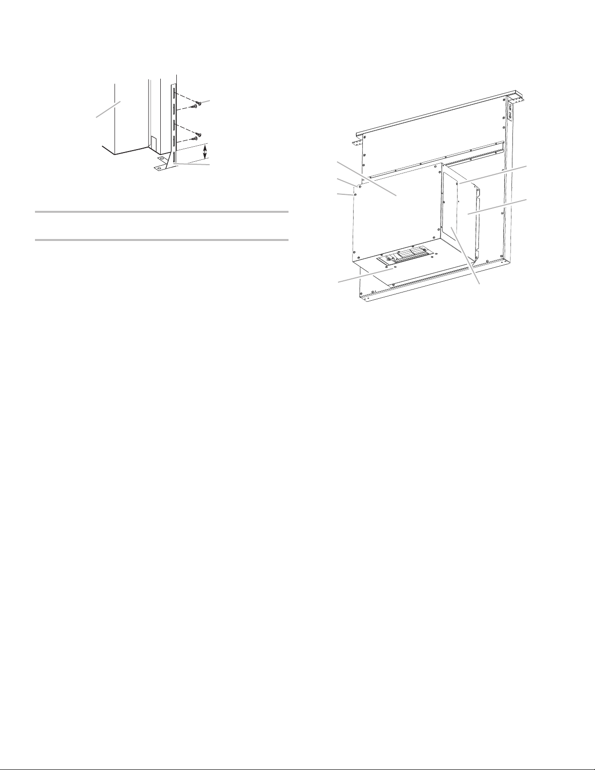
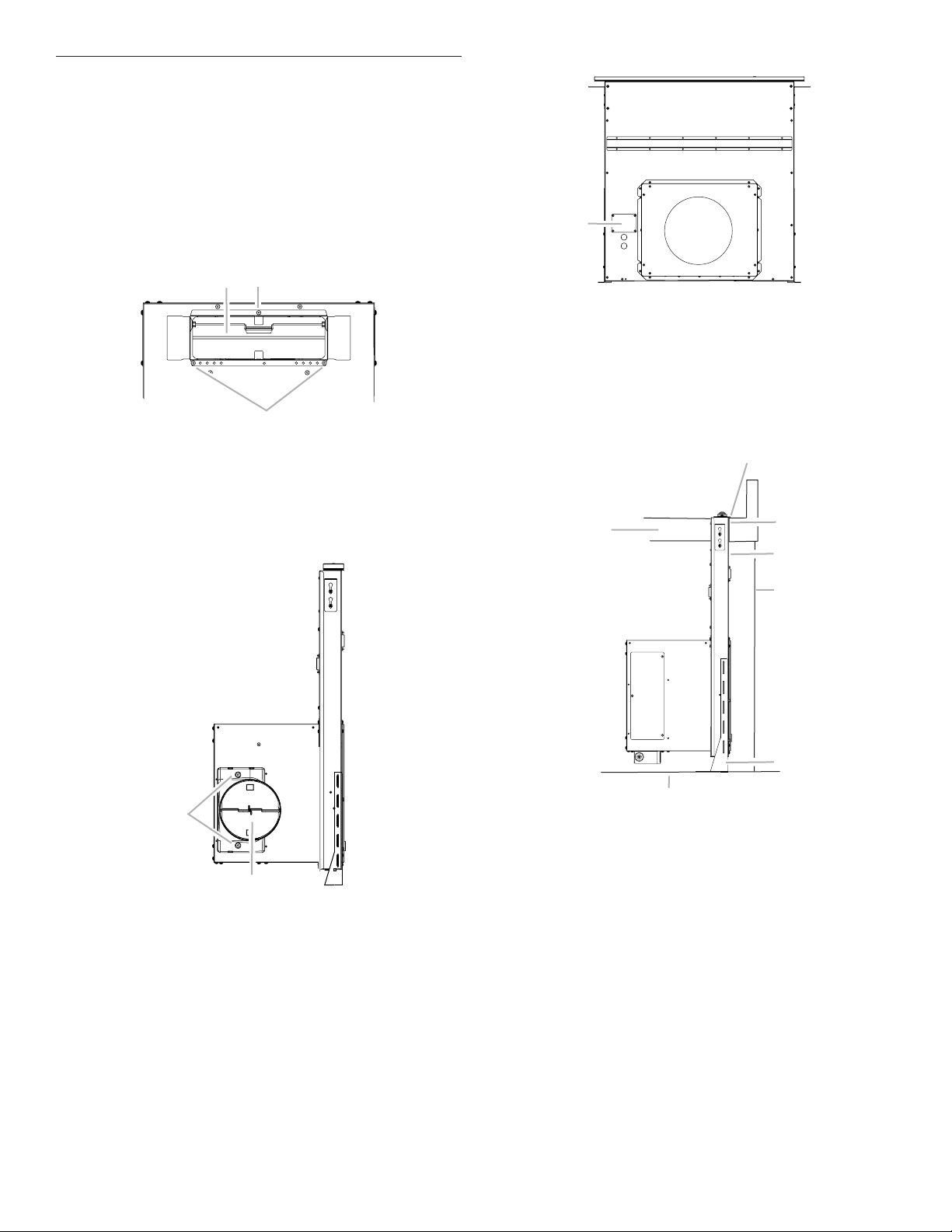
Rear Mounting — Blower Motor
A
C
A
A
B
A
C
A
B
C
NOTE: Optional blower motor rear-mounting position
(opposite side) for island cabinet location. The blower motor
box assembly can be moved to the opposite side (rear)
of the vent box.
1. Remove 7 screws from the mounting flanges of the blower
motor box.
Front View
B
A. Screws (7)
B. Keyhole slot shoulder screws (2)
C. Blower motor box
Rear View
A. Screws (6)
B. Keyhole slot shoulder screws (2)
1
C.
/4" (6.4 mm) deep cover
A
A. Deep cover
A
4. Lift the ¼" (6.4 mm) deep cover off the shoulder screws
in the keyhole slots and set the cover aside.
5. Remove the screws from the wire-mounting plate.
A. Blower motor box
2. Lift blower motor box off the shoulder screws in the keyhole
slots. Disconnect wire connection from blower motor and set
blower motor box aside.
3. Remove 6 screws from the mounting flange of the ¼" (6.4 mm)
deep cover.
A. Screws
B. Wire-mounting plate
C. Blower motor box
A
12
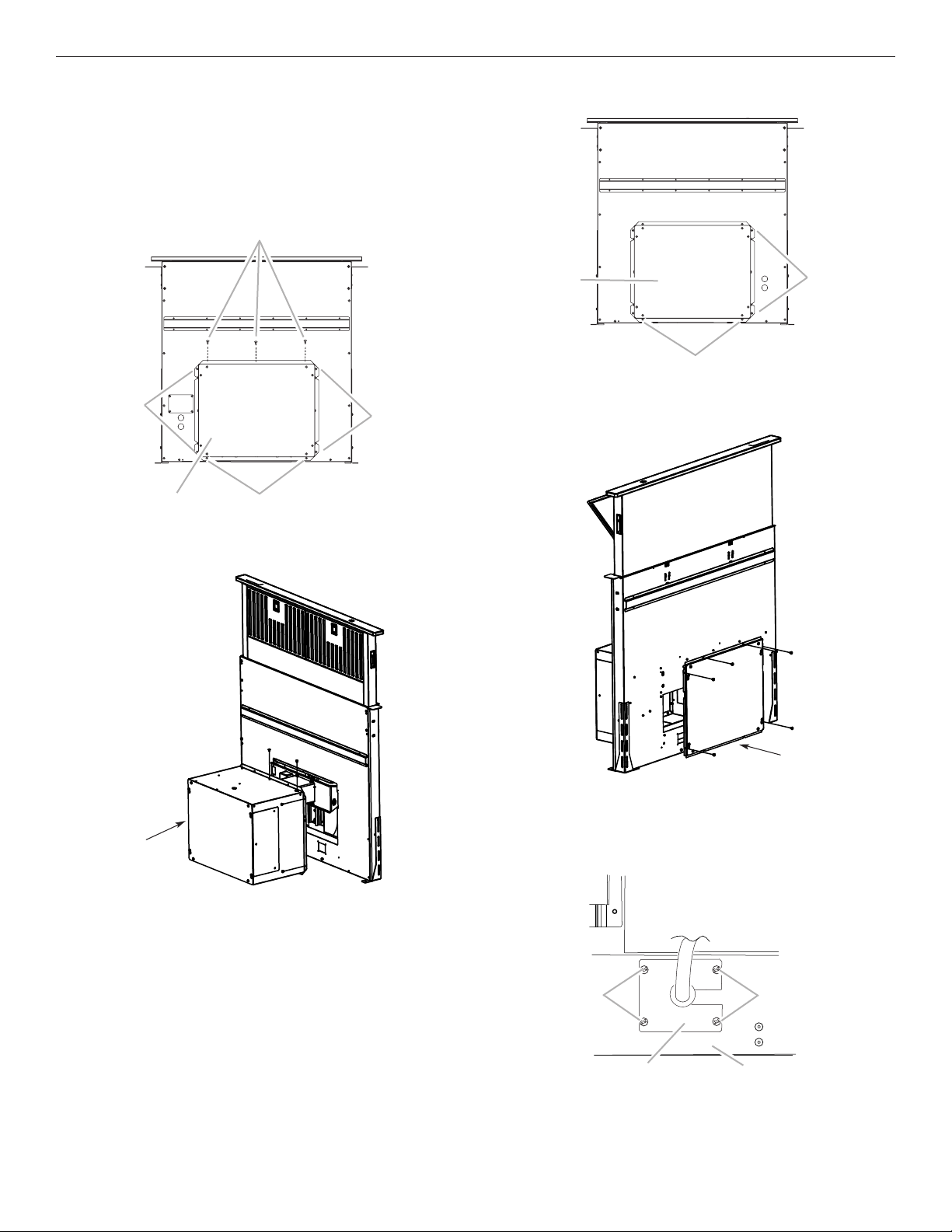
6. Hold the wire-mounting plate and push the grommet out
A
B
of the wire-mounting plate.
A. Wire-mounting plate
B. Grommet
7. Slide the wire assembly through the slot in the wire-mounting
plate to remove it.
8. Place the wire assembly through the opening to the opposite
side of the vent box.
9. Reassemble the wire assembly and grommet to the wire-
mounting plate.
10. Install the wire-mounting plate to the vent box using the
4 screws previously removed.
11. Place the blower motor box assembly with the keyhole slots
over the 2 shoulder screws on the rear of the vent box and
reconnect the wire connection to the blower motor.
12. Mount the blower motor box to the vent box and secure
using the 6 screws previously removed.
14. Remove the front cover from the deep cover, place the front
cover over the previously mounted cover box, and secure
using the 4 screws previously removed.
B
A
B
A. Deep cover
B. Front cover
C. Cover box (supplied)
C
15. Go to the “Complete Installation” section.
13. Mount the 43/4" (12.0 cm) cover box (supplied) to the front
of the vent box. Place the keyhole slots over the 2 shoulder
screws, align the mounting holes, and secure the cover box
to vent box using the 6 screws previously removed from the
¼" (6.4 mm) deep cover.
13
Complete Installation
A
B
A
B
A
A
C
B
D
F
G
NOTE: The downdraft vent system is supplied with a 31/4" x 10"
(8.3 cm x 25.4 cm) backdraft damper and a 6" (15.2 cm) round
vent transition with damper. Refer to “31/4" x 10" (8.3 cm x
25.4 cm) Backdraft Damper” or “6" (15.2 cm) Round Vent
Transition with Damper,” depending upon the type of venting
you are using.
31/4" x 10" (8.3 cm x 25.4 cm) Backdraft Damper
1. Attach the 3¼" x 10" (8.3 cm x 25.4 cm) backdraft damper
to the vent opening in the blower motor box, using three
3.5 x 9.5 mm screws.
A
A. 3.5 x 9.5 mm screws
B. 3¼" x 10" (8.3 cm x 25.4 cm) backdraft damper
6" (15.2 cm) Round Vent Transition with Damper
1. Attach the 6" (15.2 cm) round vent transition to vent opening
(left- or right-side venting only is recommended), using two
3.5 x 9.5 mm screws.
2. Remove 4 screws attaching the terminal box cover.
A. Terminal box cover
3. Determine which direction (front or rear) the home power
supply cable will enter the terminal box. Remove the
appropriate knockout from the front or rear panel and install a
1
/2" (12.7 mm) UL listed or CSA approved conduit connector.
4. Using 2 or more people, insert the downdraft vent into the
countertop cutout. Position downdraft vent so it is centered
in the cutout with the rear flange over the edge of the cutout
and the rear of the vent box against the edge of the cutout.
E
A. Rear flange of downdraft vent
B. Edge of cutout in countertop
C. Rear of downdraft vent
A. 3.5 x 9.5 mm screws
B. 6" (15.2 cm) round vent transition with damper
D. Cabinet back
E. Lower support leg
F. Cabinet floor
G. Countertop
14
 Loading...