


Jenn-Air JWD7130CDK, JWD7130CDB, JWD6030CDX, JWD7130DDW, JWD7130DDR Installation Instructions
...JENN-AIR ELECTRIC WARMING DRAWER
INSTALLATION
G U I D E
TABLE OF CONTENTS |
|
Before You Begin..................................................................... |
1-2 |
Specifications and Requirements ......................................... |
3-6 |
Guide de l’installation ................................................................. |
6 |
Guía de la Instalación ............................................................... |
12 |
Form No. B/03/03 Part No. 8101P549-60 © 2003 Maytag Appliances Sales Co. Litho U.S.A .
BEFORE YOU BEGIN
Read these instructions completely and carefully.
IMPORTANT:
•Save these instructions for the local electrical inspector’s use.
•OBSERVE ALL GOVERNING CODES AND ORDINANCES.
NOTES:
TO INSTALLER:
•Leave these instructions with the appliance after installation is completed.
TO CONSUMER:
•Keep the User Guide and Installation Instructions for future use.
•This appliance must be properly grounded.
•Insure that the power cord does not contact the hot surfaces on the bottom of ovens, cooktops, or any other appliance.
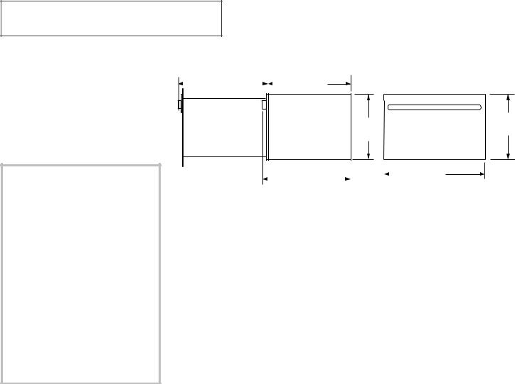
PRODUCT DIMENSIONS
27 7/16" ProStyle Front |
|
|
23 |
1 |
/4" |
|||
|
|
|||||||
|
25 1/4" Curved Front |
|
|
|
|
|
||
10 1/2"
9"
27 7/16" ProStyle Front |
|
|
|
||
|
25 1/4" Curved Front |
|
|
30" |
|
|
|
|
|
|
|
|
Including handle |
|
|
|
|
TOOLS & MATERIALS
NEEDED
•2" x 4" or 2" x 2" lumber for runners and brace
•Wood screws and adhesive or other hardware for installing runners or shelf to support warmer drawer
•Runners must be level, rigidly mounted and capable of supporting 150 pounds.
•Saw
•Level
•Drill and 1/16" bit
•Phillips screwdriver
PLANNING
The warming drawer may be installed directly into a wall or wall oven cabinetry.
The warming drawer may be installed below a countertop, a single, combo or double oven or side by side using 2 drawers.
When installing the warming drawer with a cooktop allow a 2" minimum from bottom of a cooktop burner box to top of cutout.
A 2" minimum clearance between oven and warming drawer cutouts is required.
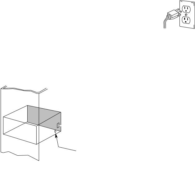
The electrical power cord is located on the right side of the warming drawer. Locate the outlet within reach of the 56" long power cord in adjacent cabinet, within 42" of the right side or 16" from the left side of the cutout. A recessed receptacle can be installed on the right side of the cutout, 7" maximum from the back of the cabinet.
REMOVE PACKAGING
AND PARTS
Parts provided: 4 Wood screws
UNPACKING
1.Place carton on a flat surface.
2.Open the top of the carton and lift off the cardboard spacer.
3.Lift the warming drawer up and out of the carton.
4.Place the drawer on top of the cardboard to protect the drawer and the finished flooring.
5.Remove all packing materials and tape.
6.Locate package containing 4 wood screws and set aside.
1
GROUNDING THE
APPLIANCE
IMPORTANT (Please read carefully)
FOR PERSONAL SAFETY, THIS APPLIANCE MUST BE PROPERLY GROUNDED.
Do not use an extension cord or adapter plug with this appliance. Follow National Electrical codes and ordinances.
This warming drawer must be supplied with 120V, 60Hz, and connected to an individual, properly grounded branch circuit, and protected by a 15 or 20 amp circuit breaker or time delay fuse.
•A properly grounded 3-prong receptacle should be located within reach of the drawer’s 56” long power cord.
•Locate the receptacle in an adjacent cabinet.
–Within 42” of the right side or,
–Within 16” of the left side or,
–A recessed receptacle may be located on the right side of the cutout,
7” maximum from the back of the cabinet. In this location, the excess power cord should be coiled to the right side of the unit using the cord clip provided.
 Recessed receptacle
 7" max. from rear on right side
 Drill 11/2" hole for
 power cord for left or right side outlet location
IMPORTANT (Please read carefully)
The power cord of this ap-
pliance is equipped with a 3-prong (grounding) plug that mates with standard 3-prong
grounding wall recep-
tacle to minimize the possibility of electric shock. The customer should have the wall receptacle and circuit checked by a qualified electrician to make sure the receptacle is properly grounded and has the correct polarity.
•Where a standard 2-prong wall receptacle is encountered, it is the personal responsibility and obligation of the customer to have it replaced with a properly grounded 3- prong wall receptacle.
Do not, under any circumstances, cut or remove the third (ground) prong from the power cord.
DO NOT USE AN EXTENSION CORD.
2

SPECIFICATIONS AND REQUIREMENTS
WHEN INSTALLING BELOW A COUNTERTOP
Drawer overlaps will conceal cut edges on all sides of the opening.
The rough opening for the drawer must be:
•Depth: 23-1/2" minimum from inside back to front of cabinet frame.
•Width: 28-1/2"
•Height: 9-1/4"
5" minimum above floor or 1" above toe kick. 23-1/4" from floor to bottom of cutout is recommended for under countertop installation.
NOTE: If you are installing in frameless cabinets, it may be necessary to install 1/2" wide cleats to accept drawer mounting screws. See drawer to find exact locations of mounting screws.
WHEN INSTALLING BELOW A COOKTOP
Warming drawers are suitable for installation below only certain specified cooktop models.
See the label attached to the top of the warming drawer for suitable models.
Install 2 x 4 or |
Electrical outlet |
Electrical outlet 42" |
11/2" Cabinet top |
|
2 x 2 anti-tip |
max. from right side |
25” |
||
flush with side of |
||||
block against |
|
|
||
cabinet 7" max. |
|
|
||
rear cabinet wall |
7” |
|
||
|
|
|||
9" from floor to |
|
|
||
|
|
|
||
bottom of block |
|
|
|
2” Min.* |
36” |
||
9” |
|
|
Countertop |
|
|
height |
|
9 |
1 |
|
|
4 |
|
||
|
/ ” |
|
|
281/2" Electrical 

outlet 16" max. from
left side
231/2” Min. |
*NOTE: When installing warming drawer below a |
|
cooktop allow a 2" minimum from bottom of |
|
cooktop burner box to top of cutout. |
3
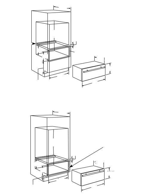
WHEN INSTALLING BELOW A WALL OVEN
Warming drawers are suitable for installation below only certain specified wall oven models.
See the label attached to the top of the warming drawer for suitable models.
Drawer overlaps will conceal cut edges on all sides of the opening.
The rough opening for the drawer must be:
•Depth: 23-1/2" minimum from inside back to front of cabinet frame.
•Width: 28-1/2"
•Height: 9-1/4"
•Allow 2" minimum between oven and drawer cutouts for clearance of overlaps.
NOTE: If you are installing in frameless cabinets, it may be necessary to install 1/2" wide cleats to accept drawer mounting screws. See drawer to find exact locations of mounting screws.
NOTE: Electrical receptacle can be installed as shown for countertop installations. Do not install receptacle above the top of the warming drawer cutout.
INSTALLATION BELOW A SINGLE OVEN
231/2" |
*NOTE: Additional clearance between cutouts may |
Min. |
|
|
be required. Check to be sure that oven supports |
|
above the warming drawer location do not obstruct |
|
the required interior 231/2" depth and 91/4" height. |
2 x 2 or 2 x 4 anti-tip |
|
|
block against rear |
|
|
|
|
|
wall 9" from floor to |
9” |
|
bottom of block |
|
|
Oven cutout
91/4" |
2” |
|
|
Min. |
|
|
Allow 5/8" |
|
|
overlap on |
231/4" |
|
all sides |
||
|
101/2"
281/2" |
|
1" Min. above toekick or adjust |
30" |
to oven installation height |
|
INSTALLATION BELOW A DOUBLE OVEN
231/2" Min.
Oven cutout
2 x 2 or 2 x 4 anti-tip
block against rear |
9” |
|
wall 9" from floor to |
||
|
||
bottom of block |
91/4" |
2811/22"" |
1" Min. above toekick
*NOTE: Additional clearance between cutouts may be required. Check to be sure that oven supports above the warming drawer location do not obstruct the required interior 231/2" depth and 91/4" height.
Allow 5/8" overlap on all sides
2” Min.

 231/4"
101/2"
30" |
4
SPECIFICATIONS AND REQUIREMENTS, CONT.
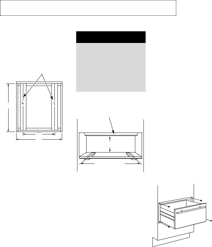
PROVIDE CABINET
SUPPORT
IMPORTANT: When installed below a single or double oven, check to be sure that any oven supports above the cutout do not obstruct the 23-1/2" required depth of the warming drawer cutout.
2" x 4" or equivalent runners
231/2"
25"
30"
•A 2" minimum clearance between oven and warming drawer cutouts is required. Additional clearance may be required if 2" x 4" blocks are used to support runners or solid floor of the oven above.
•The warming drawer may be supported by either a solid bottom, 2" x 4" or 2" x 2" runners.
•The support must be level and rigidly mounted, flush with the bottom edge of the cutout.
•There is no way to level the drawer once it has been installed. Be sure supports are level.
•The entire weight of the drawer is supported by the runners or solid floor. They must be capable of supporting 150 lbs.
ANTI-TIP BRACE
 WARNING
•An anti-tip brace must be installed to prevent the drawer from tipping forward when opened and loaded. Failure to do so could result in personal injury.
•Before installing anti-tip brace, refer to Wall Oven or Cooktop installation instructions for proper clearance of electrical conduit or power cord.
Install a 2" x 4" or 2" x 2" anti tip brace 9" above the runners and against the rear cabinet wall no more than 23" back from the face to the cabinet frame.
9"
2" x 4" or runners or solid bottom
INSTALLING THE
DRAWER
1.Slide the left corner into opening and push power cord into the hole leading to the outlet location. Thread the cord through as drawer is being pushed back into the opening.
If the outlet is installed inside the opening, plug the cord into the outlet. Coil power cord and install it in the clip on the right side of the unit. Make sure the cord does not get trapped by the drawer.
NOTE: Insure that the power cord does not contact the hot surfaces on the bottom of ovens, cooktops, or any other appliance.
2.Push the drawer back until the front flange is flush to the cabinet front.
3.Open the drawer fully.
4.Drill pilot holes through the holes in the overlapping frame, one on each corner.
5.Drive wood screws provided into each corner.
IMPORTANT: Do not operate the Warming Drawer if the decorative front kit has not been installed.
5
 Loading...