


24" (61.0 CM) AND 30" (76.2 CM) MICROWAVE
DRAWER AND 27" (68.6 CM) TRIM KIT
INSTALLATION INSTRUCTIONS
INSTRUCTIONS D’INSTALLATION DU TIROIR À FOUR À MICRO-ONDES DE 24 PO (61,0 CM) ET 30 PO (76,2 CM) ET DE LA TROUSSE DE GARNITURE DE 27 (68,6 CM)
Table of Contents/Table des matières
MICROWAVE DRAWER SAFETY................................................... |
2 |
SÉCURITÉ DU TIROIR À MICRO-ONDES.................................. |
11 |
|
INSTALLATION REQUIREMENTS................................................. |
3 |
EXIGENCES D’INSTALLATION.................................................... |
12 |
|
Tools and Parts............................................................................. |
3 |
Outillage et pièces...................................................................... |
12 |
|
Location Requirements................................................................. |
3 |
Exigences d’emplacement......................................................... |
12 |
|
Minimum Dimensions................................................................... |
3 |
Dimensions minimales................................................................ |
12 |
|
Electrical Requirements................................................................ |
4 |
Spécifications électriques........................................................... |
13 |
|
24" (61.0 CM) AND 30" (76.2 CM) STANDARD MOUNT.............. |
5 |
SUPPORT STANDARD DE |
|
|
Cabinet Preparation...................................................................... |
5 |
24 PO (61,0 CM) ET 30 PO (76,2 CM).......................................... |
14 |
|
24" (61.0 CM) AND 30" (76.2 CM) FLUSH MOUNT...................... |
6 |
Préparation de l’armoire............................................................. |
14 |
|
Cabinet Preparation...................................................................... |
6 |
EN AFFLEUREMENT DE |
15 |
|
27" (68.6 CM) TRIM KIT ACCESSORY STANDARD MOUNT |
7 |
24 PO (61,0 CM) ET 30 PO (76,2 CM).......................................... |
||
Préparation de l’armoire |
15 |
|||
Cabinet Preparation |
7 |
|||
SUPPORT STANDARD POUR TROUSSE |
|
|||
27" (68.6 CM) TRIM KIT ACCESSORY FLUSH MOUNT |
8 |
|
||
DE GARNITURE DE 27 PO (68,6 CM) |
16 |
|||
Cabinet Preparation |
8 |
|||
Préparation de l’armoire |
16 |
|||
INSTALLATION INSTRUCTIONS |
9 |
|||
EN AFFLEUREMENT POUR TROUSSE DE |
|
|||
Install the Anti-Tip Block |
9 |
|
||
GARNITURE DE 27 PO (68,6 CM) |
17 |
|||
Install the Microwave Drawer |
9 |
|||
Préparation de l’armoire |
17 |
|||
Install the Deflector Vent For Flush Installation |
10 |
|||
INSTRUCTIONS D’INSTALLATION |
18 |
|||
Complete Installation |
10 |
|||
Installation de la cale de bride antibasculement |
18 |
|||
ASSISTANCE |
10 |
|||
Installation du tiroir à micro-ondes |
18 |
|||
|
|
|||
|
|
Installer le déflecteur d’évacuation pour une |
|
|
|
|
installation en affleurement......................................................... |
19 |
|
|
|
Terminer l’installation.................................................................. |
20 |
|
|
|
ASSISTANCE................................................................................. |
20 |
IMPORTANT:
Installer: Leave installation instructions with the homeowner. Homeowner: Keep installation instructions for future reference.
IMPORTANT:
Save for local electrical inspector’s use.
IMPORTANT :
Installateur : Remettre les instructions d’installation au propriétaire.
Propriétaire : Conserver les instructions d’installation pour référence ultérieure.
IMPORTANT :
À conserver pour consultation par l’inspecteur local des installations électriques.
W11257634B
TINSKB267MRR0
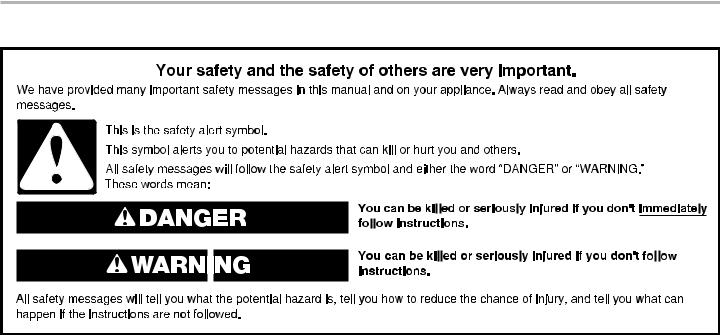
MICROWAVE DRAWER SAFETY
2
INSTALLATION REQUIREMENTS
These installation instructions cover different models. The appearance of your particular model may differ slightly from the illustrations in these Installation Instructions.
Tools and Parts
Gather the required tools and parts before starting installation. Read and follow the instructions provided with any tools listed here.
Tools needed
■■ |
Tape measure |
■■ |
1/8" (3.17 mm) drill bit |
■■ |
#2 Phillips screwdriver |
■■ |
Marker or pencil |
■■ |
Drill |
|
|
Parts supplied
The Microwave Drawer is preassembled. ■■ 1" (2.5 cm) mounting screws (4)
■■ 1" (2.5 cm) deflector screws (2) ■■ Flush mount deflector (1)
Optional Parts
■■ 27" (68.6 cm) Trim Kit (W11170223) for JMDFS24GS ■■ 27" (68.6 cm) Trim Kit (W11264778) for JMDFS24HM
Verification needed
■■ Installer must confirm presence of anti tip block. Refer to the anti-tip block section in the manual.
■■ Check local codes. Check existing electrical supply. See “Electrical Requirements”.
■■ It is required that all electrical connections be made by a licensed, qualified electrical installer.
Location Requirements
This product is suitable for use below electric or gas built-in ovens. This product is not suitable for use below cooktops.
The Microwave Drawer may be located in a cabinet or below the counter, and/or below a built-in oven. Check the opening where the Microwave Drawer will be installed. The location must provide:
IMPORTANT: Observe all governing codes and ordinances. ■■ Wood cabinetry.
■■ Cutout opening that is plumb and square. See “Minimum Cutout Dimensions” in the “Minimum Dimensions” section.
■■ Cutout floor that is solid, level, and flush with bottom of cabinet cutout.
■■ Support for weight of at least 100 lbs (45.4 kg), which includes Microwave Drawer and items placed inside.
■■ Grounded electrical outlet. See the “Electrical Requirements” section.
■■ Minimum installation clearances for installation location. See the “Minimum Dimensions” section.
■■ Complete enclosure around the recessed portion of the Microwave Drawer.
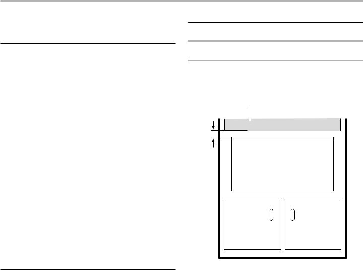
Minimum Dimensions
Minimum Wall Oven Combination Installation
Clearances
For proper installation, the following minimum clearances must exist above and below the cutout opening.
NOTE: Upper oven must have heat deflector kit installed to direct exhaust away from microwave console (Refer to Wall Oven Manual for Deflector Kit Installation)
A
2" (5.1 cm)
B
A.Upper oven cutout
B.Microwave drawer cutout
3
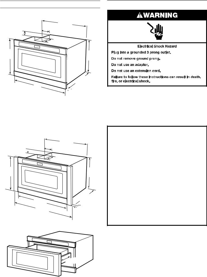
Product Dimensions
24" (61.0 cm) and 30" (76.2 cm)
4¹¹⁄" |
21 |
/ " |
|
(54.9 cm) |
|||
(11.9 cm) |
|||
|
|
||
1 ³/ " (4.4 cm) |
|
|
|
16" |
|
14 ⁄ " |
|
(40.6 cm) |
|
(37.1 cm) |
|
|
|
||
22 ¹/ "
(56.0 cm)
A
 B
B
Dimension A:
24" (61.0 cm) Product - 237/8" (60.6 cm) 30" (76.2 cm) Product - 2915/16" (76.0 cm) Dimension B:
JMDFS24GS Model - 15/8" (4.1 cm) JMDFS30HL Model - 111/16" (4.3 cm) JMDFS24HM Model - 13/4" (4.4 cm) JMDFS30HM Model - 13/4" (4.4 cm)
Optional 27" (68.6 cm) Trim Kit:
4¹¹⁄" |
21 |
/ " |
|
(54.9 cm) |
|||
(11.9 cm) |
|||
|
|
||
1 ³/ " (4.4 cm)
16"
(40.6 cm)
23 / "
(60.6 cm)
26 ³/ "
(68.0 cm)
14 ⁄ "
(37.1 cm)
22 ¹/ "
(56.0 cm)
 1/ " (4.1 cm)
The drawer opens 151/4" (38.7 cm).
15 ¹/ " (38.7 cm)
Electrical Requirements
IMPORTANT: Observe all governing codes and ordinances.
Required:
■■ A 120 V, 60 Hz, AC-only, 15 or 20 A electrical supply with a fuse or circuit breaker.
Recommended:
■■ A time-delay fuse or time-delay circuit breaker
■■ A separate circuit serving only this Microwave Drawer
GROUNDING INSTRUCTIONS
■For all cord connected appliances:
The microwave oven must be grounded. In the event of an electrical short circuit, grounding reduces the risk of electric shock by providing an escape wire for the electric current. The microwave oven is equipped with a cord having a grounding wire with a grounding plug. The plug must be plugged into an outlet that is properly installed and grounded.
WARNING: Improper use of the grounding plug can result in a risk of electric shock. Consult a qualified electrician or serviceman if the grounding instructions are not completely understood, or if doubt exists as to whether the microwave oven is properly grounded.
Do not use an extension cord. If the power supply cord is too short, have a qualified electrician or serviceman install an outlet near the microwave oven. A short power supply cord is provided to reduce the risks resulting from becoming entangled in or tripping over a longer cord.
SAVETHESE INSTRUCTIONS
4
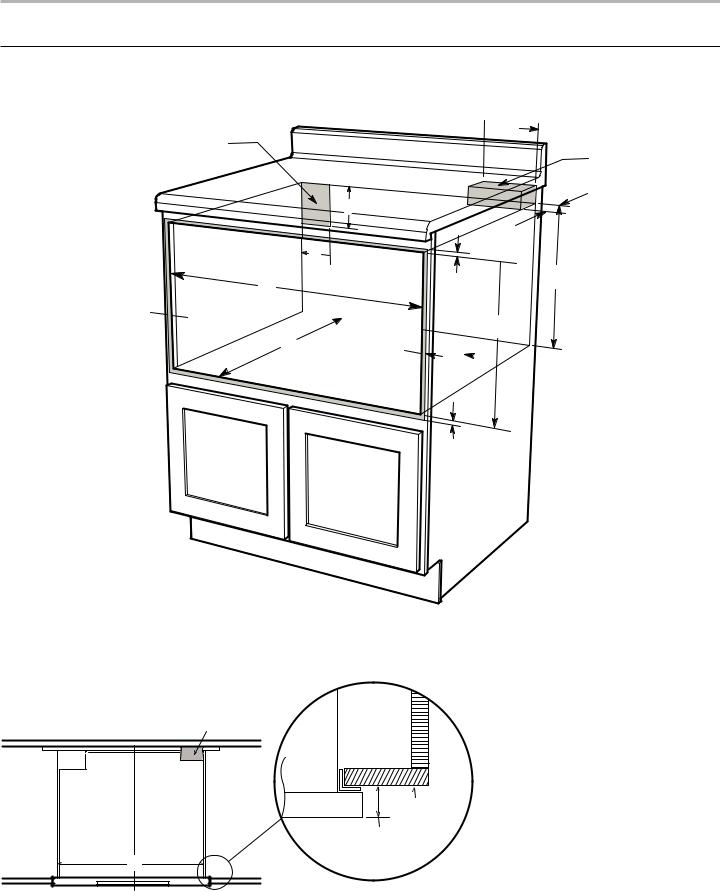
24" (61.0 CM) AND 30" (76.2 CM) STANDARD MOUNT
Cabinet Preparation
Cabinet Dimensions
 A
A
B
C
E
D
 F
F 
G K  H
H

 I
I  M
M
J I 
 L
L
N
Anti-Tip block
O Cabinet
face
Drawer
face
G
Top view
A.6" (152.40 mm) minimum
16" (406.40 mm) maximum
B.Suggested electrical receptacle location
C.Anti-Tip block
D.3" (76.20 mm)
E.31/2" (88.90 mm)
F.4.5" (114.30 mm)
G.221/8" (561.98 mm) opening
H.1413/16" (376.24 mm) to bottom of Anti-Tip block
I.24" models: Allow 7/8" (22.2 mm) overlap
30" models: Allow 41/16" (103.19 mm) overlap
J.24" (609.60 mm) minimum depth
K.Allow 9/16" (5.62 mm)
L.Platform must support 100 lb (45.4 kg)
M.159/16" (395.27 mm) opening
N.Allow 3/4" (19.05 mm) overlap
O.JMDFS24GS Model - 15/8" (41.28 mm) JMDFS30HL Model - 111/16" (42.86 mm) JMDFS24HM Model - 13/4" (44.45 mm) JMDFS30HM Model - 13/4" (44.45 mm)
5

24" (61.0 CM) AND 30" (76.2 CM) FLUSH MOUNT
Cabinet Preparation
Cabinet Dimensions
A
B
C
E
D
|
|
F |
|
|
G |
|
R |
O |
I |
|
|
|
K |
H
Note: The face of the shelf must sit 1 / " (47.6 mm) back from
  the face of the cabinet.
M
L

 J
J
N
Shelf face L
Cabinet face
Flush mount de ector vent
³/ " (19.05 mm)
Anti-Tip block
K |
Top view
Mounting |
cleat |
Drawer |
P |
Q |
Cabinet |
face |
face |
A.6" (152.40 mm) minimum 16" (406.40 mm) maximum
B.Suggested electrical receptacle location
C.Anti-Tip block
D.3" (76.20 mm)
E.31/2" (88.90 mm)
F.4.5" (114.30 mm)
G.24" models: 243/16" (614.4 mm) minimum 30" models: 301/4" (768.4 mm) minimum
H.1413/16" (376.24 mm) to bottom of Anti-Tip block
I.1" (25.40 mm) minimum
J.24" (609.60 mm) minimum depth
K.221/8" (561.98 mm) “mounting cleat to mounting cleat”
L.17/8" (47.62 mm)
M.167/8"(428.62 mm) opening
N.Platform must support 100 lb (45.4 kg)
O.161/8" (409.56 mm)
P.0" (0 mm) = flush
Q.JMDFS24GS Model - 15/8" (41.28 mm) JMDFS30HL Model - 111/16" (42.86 mm) JMDFS24HM Model - 13/4" (44.45 mm) JMDFS30HM Model - 13/4" (44.45 mm)
R.159/16" (395.3 mm)
6
 Loading...