


|
FOR SERVICE TECHNICIAN’S USE ONLY |
Tech Sheet |
Do not remove or destroy |
|
|
Electrical Shock Hazard
Only authorized technicians should perform diagnostic voltage measurements.
After performing voltage measurements, disconnect power before servicing.
Failure to follow these instructions can result in death or electrical shock.
ARNING
Electrical Shock Hazard Disconnect power before servicing.
Replace all parts and panels before operating.
Failure to do so can result in death or electrical shock.
Voltage Measurement Safety Information
When performing live voltage measurements, you must do the following:
■Verify the controls are in the off position so that the appliance does not start when energized.
■Allow enough space to perform the voltage measurements without obstructions.
■Keep other people a safe distance away from the appliance to prevent potential injury.
■Always use the proper testing equipment.
■After voltage measurements, always disconnect power before servicing.
W11202275A |
11/18 |

FOR SERVICE TECHNICIAN’S USE ONLY
IMPORTANT: Electrostatic Discharge (ESD) Sensitive Electronics
ESD problems are present everywhere. ESD may damage or weaken the electronic control assembly. The new control assembly may appear to work well after repair is finished, but failure may occur at a later date due to ESD stress.
■Use an antistatic wrist strap. Connect wrist strap to green ground connection point or unpainted metal in the appliance
-OR-
Touch your finger repeatedly to a green ground connection point or unpainted metal in the appliance.
■Before removing the part from its package, touch the antistatic bag to a green ground connection point or unpainted metal in the appliance.
■Avoid touching electronic parts or terminal contacts; handle electronic control assembly by edges only.
■When repackaging failed electronic control assembly in antistatic bag, observe above instructions.
Table of Contents |
|
OVEN COMPONENTS.................................................................................................................................................... |
3 |
CONTROL KNOBS......................................................................................................................................................... |
5 |
DIAGNOSTICS................................................................................................................................................................ |
8 |
FAULT/ERROR CODES & TROUBLESHOOTING STEPS........................................................................................... |
12 |
DIAGNOSTIC TESTS..................................................................................................................................................... |
17 |
STRIP CIRCUIT TABLE - 30" (76.2 CM) OR 36" (91.4 CM) RIGHT OVEN................................................................. |
36 |
STRIP CIRCUIT TABLE - 18" (45.7 CM) LEFT OVEN.................................................................................................. |
38 |
CONTROL BOARDS COMPONENT LOCATION......................................................................................................... |
40 |
PIN-OUT......................................................................................................................................................................... |
44 |
2

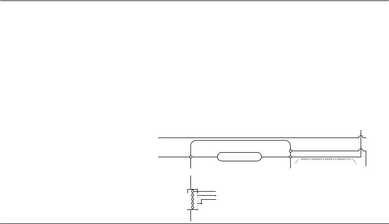
Oven Components
Component Locations
|
Front of unit |
|
|
Rear of unit |
|
|
|
|
O |
|
|
|
|
N |
|
|
F |
|
M |
|
|
|
|
|
D |
E |
|
|
|
|
|
G |
H |
|
|
|
|
|
|
C |
|
|
I |
L |
|
|
|
||
|
|
|
|
|
B |
|
|
|
K |
A |
|
|
|
|
|
|
|
|
A.18" (45.7 cm) oven: Meat probe jack (located behind the panel)
B.18" (45.7 cm) oven: left halogen light
C.Spark module
D.Cooling Fan
E.Temperature sensor for griddle
J
F.Griddle element
G.User interface
H.Griddle knob
I. 30" (76.2 cm) oven: Meat probe jack (located behind the panel)
J.Door latches
K.30" (76.2 cm) oven: right convection fans
L.30" (76.2 cm) oven: right halogen light
M.30" (76.2 cm) oven: oven shutdown thermal cutoff (non-resettable)
N.30" (76.2 cm) oven: right convection element
O.30" (76.2 cm) oven: temperature sensor
WV
P.Broil (DSI)
Q.Bake (DSI)
R.18" (45.7 cm) oven: temperature sensor
S.18" (45.7 cm) oven: oven shutdown thermal cutoff (non-resettable)
P
Q
R
 S
S
 T
T
 U
U
T.18" (45.7 cm) oven: convection fan
U.Gas pressure regulator
V.Relay Expansion Control Board (Left Oven)
W.PowerMax Main Control Board (ACU)
3
FOR SERVICE TECHNICIAN’S USE ONLY
Calibration
The oven temperatures have been calibrated and there is no adjustment available to the user or service technician. Refer the error code and oven sensor test sections as needed.
Serviceability
Oven Components |
Front/Rear/Bottom |
|
Serviceable |
User interface board |
Front |
|
|
Appliance manager |
Bottom |
|
|
Halogen lights |
Front |
|
|
Door switch |
Front and Top |
|
|
Latch switch |
Front and Top |
|
|
Latch motor |
Front and Top |
|
|
Oven temperature sensor |
Front |
|
|
Meat probe sensor |
Probe - front |
|
|
Cooling Fan |
Rear and Top |
|
|
Thermal cutoff (non-resettable) |
Rear |
|
|
Oven convection fan motor |
Rear |
|
|
Oven convection ring element |
Rear |
|
|
Griddle |
Top and Rear |
|
|
NOTE: Door must be removed in order to remove or replace kick plate. Refer to the installation instructions for more information.
4
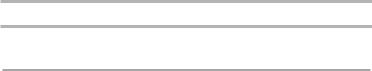
Cooktop Knobs and Buttons
A
B
C
ALeft Rear Knob
BLeft Front Knob
CGrill Knob
DOven Light Button
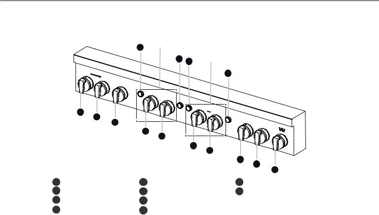
Control Knobs
48" (121.9 CM)
Controls left
D cavity
Controls right
G D cavity
G
E |
F |
|
|
|
|
|
|
|
|
|
E |
F |
|
|
|
|
|
|
|
|
|
|
H |
I |
|
|
|
|
|
|
|
|
|
J |
E |
Mode Knob |
|
I |
Center Front Knob |
F |
Temperature Knob |
J |
Griddle Knob |
|
G Oven Start Button |
|
|
|
|
H |
Center Rear Knob |
|
|
|
NOTE: Cooktop configuration, features, and controls may differ.
5
FOR SERVICE TECHNICIAN’S USE ONLY
Indicator Lights
A C
A B C D
E
F
D
|
|
G |
|
A |
Mode Knob Indicator Light |
E |
Griddle Preheat Light |
B |
Remote Indicator |
F |
Griddle Cooktop ON Light |
C Temperature Knob Indicator Light |
G |
Wi-Fi Indicator |
|
D |
Start Button Indicator Light |
|
|
NOTE: Cooktop configuration, features, and controls may differ.
6
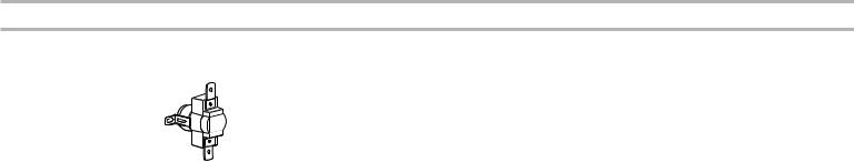
Oven Shutdown Thermal Cutoff (non-resettable)
The oven shutdown thermal cutoff (non-resettable) is located at the back of the oven. It will shut down the burners if the temperature at the back of the oven exceeds component limits.
Verify that the oven shutdown thermal cutoff (non-resettable) is OK.
To replace this thermal cutoff (non-resettable):
1. |
Refer to the following chart for the correct Part Number. |
||
|
|
|
|
Part Number |
Opening Temp. |
Marking (with Black |
|
|
|
|
Letters) |
|
|
|
|
4449751 |
338ºF ± 11.7ºF |
Red label |
|
|
|
(170ºC ± 6.5ºC) |
|
2. |
Unplug range or disconnect power. |
|
|
3. |
Replace the oven thermal cutoff (non-resettable). |
|
|
4. |
Replace all parts and panels before operating. |
|
|
5. |
Plug in range or reconnect power. |
|
|
7

FOR SERVICE TECHNICIAN’S USE ONLY
Diagnostics
Unplug range or disconnect power before performing the following checks: ■■ Make sure there is power at the wall outlet.
■■ Has a household fuse blown or circuit breaker tripped? Was a regular fuse used? Inform customer that a time-delay fuse is required.
■■ A potential cause of a control not functioning is corrosion on connections. Observe connections and check for continuity with an ohmmeter.
■■ All tests/checks should be made with a VOM or DVM having a sensitivity of 20,000 Ω per VDC or greater.
■■ Check all connections before replacing components, looking for broken or loose wires, failed terminals, or wires not pressed into connectors far enough. Damaged harnesses must be entirely replaced. Do not rework a harness.
■■ Resistance checks must be made with power cord unplugged from outlet, and with wiring harness or connectors disconnected.
■■ When removing AC power, allow time for the main control (ACU) to completely power down. At a minimum, leave AC power removed for one minute.
IMPORTANT: Do not replace the control if there is no evidence of any failure.
There are two service diagnostics modes implemented on the Main (right for double oven models) user interface board including: Fault Code Display and Manual Diagnostic modes.
To Enter Diagnostics Mode:
Before proceeding with any corrective action, perform the following steps to enter the Diagnostics mode:
With the appliance in standby mode, perform a sequence of 6 movements using the Mode Selector knob.
1.To start the movements, the knobs shall consider as initial position, Bake for the Mode Selector knob and Off for the Temperature knob.
2. Turn the Mode Selector knob.
one position; pause for 2 seconds
one position; pause for 2 seconds
one position; pause for 2 seconds
one position; pause for 2 seconds
one position; pause for 2 seconds
one position; pause for 2 seconds
NOTE: This sequence must be performed within 2 minutes.
3.Successful entry will be indicated by all UI LEDs flashing ON/OFF for a half second and a tone will sound.
To Exit Diagnostics Mode:
NOTE: If there is no interaction for a 5-minutes period, Diagnostics Mode will timeout.
Diagnostics Mode can be exited in one of the following ways:
■■ Rotate Mode Selector knob to the BAKE position, Rotate the Off/Temperature knob to OFF position, then press Start button after 1 second. A tone will sound for successful exit.
■■ Remove the AC power from the appliance.
After exiting Diagnostics Mode, the appliance will return to Standby Mode.
8

Navigating Diagnostics Mode
While in Diagnostics Mode, the following modes are available to be selected: ■■ FAULT CODE DISPLAY
■■ MANUAL DIAGNOSTIC
To select a mode, rotate the Mode Selector knob clockwise until desired mode is indicated by the UI LEDs, then press Start Button.
Fault Code Display
Top LEDs on
Manual Diagnostics
Top and right
LEDs on
Fault Code History Mode:
This mode provides the ability to check the last ten faults stored in the memory. Because the UI utilizes LEDs and a speaker for communication, errors are displayed through specific LEDs to indicate the fault and error code (F# E#) format.
■■ The Wi-Fi LED turns on to indicate that the fault (F) code number (#) is being displayed.
■■ The Remote LED turns on to indicate that the error (E) code number (#) is being displayed.
■■ The eight LEDs of the back-lit Mode Selector knob flash ON/OFF to display the fault and errors code numbers (#’s). A number is represented by the number of times the LED flashes ON/OFF. For example to display “F5”, Wi-Fi indicator will be ON and the Mode Selector knob LEDs will flash ON/OFF five times.
B
NOTE: You must exit the current mode in order to access and navigate to the other available modes.
C A
AWi-Fi LED turned on indicates Fault (F) Display mode.
BRemote LED turned on indicates Error (E) Display mode.
CKnob LEDs flash indicates F (Fault) or Error (E) code Numbers (#'s)
9
FOR SERVICE TECHNICIAN’S USE ONLY
■■ Errors stored in the memory will be displayed from the most recent occurrence to the oldest.
■■ The Fault (F) Wi-Fi LED turns ON and the knob LEDs flash the corresponding number (#). Then the UI is blank for a half second before displaying the Error (#) code.
■■ There is a 1 second delay between each fault/error code (F# E#).
■■ Errors will continue to be displayed until the mode is exited or the mode times out.
■■ If there are no additional errors in the memory (OR if there are no errors at all), the speaker will tone 3 times and the first error will be displayed again.
NOTE: If the error (E) number is zero (“0”), then only the fault (F) number is displayed for that code.
To clear: After review, the stored error codes can be cleared out or erased. To clear all error codes, press the Start button once.
10
Manual Diagnostics Mode:
The Manual Diagnostic Mode allows the technician to manually actuate each relay for testing purposes.
■■ Enter Manual Diagnostic Mode by rotating the Mode Knob clockwise until the mode id number is displayed by the LEDs.
■■ Once in Manual Diagnostic Mode, rotate the Mode knob or Temperature knob clockwise, to activate the corresponding relay to each element.
NOTE: For the left cavity use the same operation to enter Manual Diagnostics Mode.
Each position reached while rotating the knob will turn the elements On/Off according to the list below:
Knob Position |
Relay Activated |
Temperature Knob - Keep Warm |
(Right Bake Burners) On/Off |
|
|
Temperature Knob - Broil Lo |
(Right Broil Burners) On/Off |
|
|
Mode Knob - Convect |
(Right Convect Element) On/Off |
|
|
Temperature Knob - Clean |
(Right Motorized Door Lock) On/Off |
|
|
Button - Oven Light |
(Right Cavity Light) On/Off |
|
|
Temperature Knob - Bread Proof |
(Right Convect Fan) On/Off |
|
|
Knob Position |
Relay Activated |
Mode Knob - Bake |
(Right Cooling Fan Lo speed) On/Off |
|
|
Mode Knob - Broil |
(Right Cooling Fan Hi Speed) On/Off |
NOTES:
■■ For the left cavity use the same table but use the left knob instead. ■■ Mode knob only supports clockwise rotating.
■■ Any new knob movement will turn the current element/burner/fan off.
In order to test the second oven cavity, follow the same test sequence and procedure.
NOTE: If no action is taken within 5 minutes, the mode times out.
11
FOR SERVICE TECHNICIAN’S USE ONLY
Fault/Error Codes &Troubleshooting Steps
The fault codes below may be indicated under various conditions and can be accessed through Service Diagnostics.
Fault codes are displayed by alternately showing F# and E#. All fault codes have an F# and an E#. The F# indicates the suspect System/Category. The E# indicates the suspect Component system.
Display |
EXPLANATION AND RECOMMENDED PROCEDURE |
F1E0 |
Check User Interface Board - EEPROM Communication Error |
|
|
|
The user interface board(s) is locked up due to an unexpected internal communication error. This is often corrected by cycling power. |
|
|
|
Possible Causes: Software/EEPROM or Internal UI Board memory chip failure. |
|
Recommended Procedure: See TEST #4 (User Interface Input Voltage and Communication) on page 20. |
|
|
F1E1 |
Control Relay Board - EEPROM Communication Error |
|
|
|
Immediately after the Oven control sees an unexpected event. |
|
|
|
Possible Causes: There may be a problem with the oven control(s) or the associated wiring. |
|
Recommended Procedure: See TEST #1 and #2 (Main Control [ACU]) on page 17 and 18. |
|
|
F2E1 |
Stuck Key - Button Functionality Error |
|
|
|
Start button or Light Button has lost function. |
|
|
|
Possible Causes: A keypad has been pressed for an extended period of time. |
|
The result of the user pressing a keypad for too long. |
|
Recommended Procedure: See TEST #12 (Start or Light Button) on page 30. |
|
|
F2E2 |
Oven Knob - Rotary Encoder Open/Shorted |
|
|
|
Problem with the user interface board(s) - Rotary Encoder Open/Shorted. |
Possible causes: Rotary Encoder Open/Shorted. Can occur within 120 seconds of rotary encoder open/shorted.
Recommended Procedure: See TEST #13 (Knob) on page 31.
12

Display |
EXPLANATION AND RECOMMENDED PROCEDURE |
F3E0 |
Main Oven Sensor Open or Shorted |
|
|
|
Main oven temperature reading greater than 995°F (535°C) or less than 0°F (-18°C). |
|
|
|
Possible Causes: Main Oven Sensor Open or Shorted. Can occur within 60-120 seconds of activating a cook or clean function or when |
|
idling. |
|
Recommended Procedure: See TEST #5 (RTD Main Oven Temperature Sensor) on page 21. |
|
|
F3E1 |
Left Oven Sensor Open or Shorted |
|
|
|
Main oven temperature reading greater than 995°F (535°C) or less than 0°F (-18°C). |
|
|
|
Possible Causes: Left Oven Sensor Open or Shorted. Can occur within 60-120 seconds of activating a cook or clean function or when |
|
idling. |
|
Recommended Procedure: See TEST #6 (RTD Main Oven Temperature Sensor) on page 22. |
|
|
F3E3 |
Main Oven Meat Probe Short-Circuit |
|
|
|
Possible Causes: There may be a problem with the meat probe temperature sensor, the associated user interface board, or the |
|
associated wiring. |
|
Recommended Procedure: See TEST #7 (meat Probe & Jack or Main Oven Meat Probe short-circuit) on page 23. |
|
|
F3E9 |
Left Oven Meat Probe Short-Circuit |
|
|
|
Possible Cause: Problem with the meat probe temperature sensor, the associated user interface board, or the associated wiring. |
|
Recommended Procedure: See TEST #7 (meat Probe & Jack or Left Oven Meat Probe short-circuit) on page 23. |
|
|
F5E0 |
Main Oven Door Latch Switch |
|
|
|
Door latch switch doesn’t close or open as expected. It may occur if there is a door latch switch failure or a door latch motor failure. |
|
|
|
Possible Causes: There may be a problem with the main oven door latch assembly, the door switch, or the associated wiring. |
|
Recommended Procedure: Use TEST #8 on page 24, to check door switch function. |
|
Then Use TEST #9 on page 25, to check door latch motor and latch switch function. |
|
|
F5E1 |
Main Oven Door Latch Motor |
|
|
|
Door latch switch doesn’t close or open as expected. It may occur if there is a door latch switch failure or a door latch motor failure. |
Possible Causes: There may be a problem with the main oven door latch assembly or the associated wiring.
Recommended Procedure: Use TEST #8 on page 24, to check door switch function.
Then Use TEST #9 on page 25, to check door latch motor and latch switch function.
13

|
FOR SERVICE TECHNICIAN’S USE ONLY |
Display |
EXPLANATION AND RECOMMENDED PROCEDURE |
F5E3 |
Left Oven Door Latch Switch |
|
|
|
Door latch switch doesn’t close or open as expected. It may occur if there is a door latch switch failure or a door latch motor failure. |
|
|
|
Possible Cause: Problem with the left oven door latch assembly, the door switch, or the associated wiring. |
|
Recommended Procedure: Use TEST #8 to on page 24, check door switch function. |
|
Then Use TEST #9 on page 25, to check door latch motor and latch switch function. |
|
|
F5E4 |
Left Oven Door Latch Motor |
|
|
|
Door latch switch doesn’t close or open as expected. It may occur if there is a door latch switch failure or a door latch motor failure. |
|
|
|
Possible Cause: Problem with the left oven door latch assembly or the associated wiring. |
|
Recommended Procedure: Use TEST #8 on page 24, to check door switch function. |
|
Then Use TEST #9 on page 25, to check door latch motor and latch switch function. |
|
|
F6E0 |
User Interface Connection |
|
|
|
Lost Communication of left cavity HMI |
|
|
|
Possible Causes: Problem with the oven control(s), the user interface board(s), or the associated wiring. Can occur within |
|
60 - 120 seconds of the fault condition when communication between ACU and HMI is lost. |
|
Recommended Procedure: See TEST #4 (User Interface Input Voltage and Communication) on page 20. |
|
|
F6E1 |
Main Oven Over Temperature Limit |
|
|
|
Oven temperature is greater than 601°F (316°C), or oven temperature is greater than 900°F (482°C) in self clean. The affected oven will |
|
be locked out until the control detects an oven temperature less than 601°F (316°C), or less than 900°F (482°C) in self clean. Can occur |
|
within 60 - 120 seconds of the control detecting an oven temperature condition. |
|
|
|
Possible Causes: Problem with the main oven temperature sensor, main oven control, or the associated wiring. |
|
Recommended Procedure: See TEST #5 (RTD Main Oven Temperature Sensor) on page 21. |
|
|
F6E3 |
Left Oven Over Temperature Limit |
|
|
|
Oven temperature is greater than 601°F (316°C), or oven temperature is greater than 900°F (482°C) in self clean. The affected oven will |
|
be locked out until the control detects an oven temperature less than 601°F (316°C), or less than 900°F (482°C) in self clean. |
Possible Causes: There may be a problem with the left oven temperature sensor, left oven control, or the associated wiring. Can occur within 60 - 120 seconds of the control detecting an oven temperature condition.
Recommended Procedure: See TEST #6 (RTD Left Oven Temperature Sensor) on page 22.
14

Display |
EXPLANATION AND RECOMMENDED PROCEDURE |
F6E4 |
Control Status |
|
|
|
Oven User Interface UI and ACU state status mismatch. |
|
|
|
Possible Causes: Problem with the main oven control. Can occur within 60 - 120 seconds of the fault condition when the UI and ACU |
|
status mismatch. |
|
Recommended Procedure: See TEST #14 (UI & ACU Mismatch) on page 31. |
|
|
F6E6 |
Main Oven Control Connection |
|
|
|
Possible Causes: There may be a problem with the main control or the associated wiring. Can occur within 60 - 120 seconds of the |
|
fault condition when communication between the ACU and HMI is lost. |
|
Recommended Procedure: See TEST #2 (Communication of Main control (ACU)) on page 18. |
|
|
F6E9 |
Left Oven Control Connection |
|
|
|
Possible Causes: There may be a problem with the main control or the associated wiring. Can occur within 60 - 120 seconds of the |
|
fault condition when communication between the ACU and REB is lost. |
|
Recommended Procedure: See TEST #3 (Relay Expansion Control Board (Left Oven)) on page 19. |
|
|
F8E0 |
Main oven Cooling Fan speed low or Not Functioning |
|
|
|
Main oven Cooling Fan speed too low (fan speed below 500 rpm). |
|
|
|
Possible Causes: The fan is spinning too slowly or there is a problem with the Hall Effect sensor. Can occur within 60 - 120 seconds of |
|
a fault condition when cavity temperature is above 349°F (176°C). |
|
Recommended Procedure: See TEST #10 (Main Oven (Right) Cooling Fan) on page 27. |
|
|
F8E1 |
Left Oven Cooling Fan Speed Low |
|
|
|
Main oven Cooling Fan speed too low (fan speed below 500 rpm). |
Possible Causes: The fan is spinning too slowly or there is a problem with the Hall Effect sensor.
There may be a problem with an airflow restriction, the left oven cooling fan, the left oven control, or the associated wiring. Can occur within 60 - 120 seconds of a fault condition when cavity temperature is above 349°F (176°C).
Recommended Procedure: See TEST #11 (Secondary (Left) Oven Cooling Fan) on page 29.
15
|
FOR SERVICE TECHNICIAN’S USE ONLY |
|
|
Display |
EXPLANATION AND RECOMMENDED PROCEDURE |
|
|
F8E2 |
Main Oven Cooling Fan Speed High |
|
|
|
Cooling Fan Speed too high (fan speed above 5,000 rpm). |
|
|
|
Possible Causes: Fan is spinning too quickly or there is a problem with the Hall Effect sensor. |
|
There may be a problem with an airflow restriction, the main oven cooling fan, the main oven control, or the associated wiring. Can |
|
occur within 60 - 120 seconds of a fault condition when cavity temperature is above 349°F (176°C). |
|
Recommended Procedure: See TEST #10 (Main Oven (Right) Cooling Fan) on page 27. |
|
|
F8E3 |
Left Oven Cooling Fan Speed High |
|
|
|
Cooling Fan speed too high (fan speed above 5,000 rpm). |
|
|
|
Possible Causes: the fan is spinning too quickly or because there is a problem with the Hall Effect sensor. There may be a problem with |
|
an airflow restriction, the left oven cooling fan, the left oven control, or the associated wiring. Can occur within 60 - 120 seconds of a |
|
fault condition when cavity temperature is above 349°F (176°C). |
|
Recommended Procedure: See TEST #11 (Secondary (Left) Oven Cooling Fan) on page 29. |
|
|
F9E0 |
Power Input - Product is mis-wired |
|
|
|
Possible Causes: The electrical outlet in the home may be mis-wired. |
|
Recommended Procedure: See TEST #15 (Power Input) on page 31. |
|
|
16
DiagnosticTests
IMPORTANT: The following procedures may require the use of needle probes to measure voltage. Failure to use needle probes will damage the connectors. To ease the process of measuring voltage and resistance, test points for each pin are accessible through the slots in the plastic beneath each CCU connector.
Test Name |
Description |
Steps |
|
TEST #1 |
This test checks for incoming and |
1. |
Unplug range or disconnect power. |
Main Control |
outgoing power to and from the |
2. |
Remove door and toe panel to access main control. |
(ACU) |
main control. This test assumes |
3. |
Verify that ALL connectors are inserted all the way into the main control. |
|
that proper voltage is present at |
4. |
With a voltmeter set to AC, connect black probe to J5-2 (Neutral) and red probe to J5-1 (L1). |
|
the outlet. |
||
|
Example: |
5. |
Plug in range or reconnect power. |
|
|
|
|
■■ 14 VDC output from ACU |
■■ If 120 |
VAC is present, unplug range or disconnect power and go to step 6. |
|
■■ If 120 |
VAC is not present, unplug range or disconnect power and check the AC power cord |
||
|
|||
|
for continuity. |
||
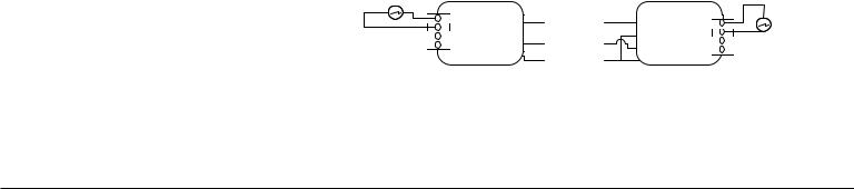
6.Disconnect P9, use a voltmeter set to DC, connect black probe to P9-1 (GND) and red probe to P9-5 (+14 V) on the board. Plug in range or reconnect power. If DC 14 V is not present, unplug range or disconnect power and change main control. If DC 14 V is present, unplug range or disconnect power.
7.Reassemble all parts and panels. Plug in range or reconnect power.
|
POWERMAX |
P6-5 |
Feedback for current sensing |
|
L1 |
P6-1 |
P6-3 |
N |
|
Power Supply |
||||
|
|
|
|
P9 |
VDC |
|
GND |
|
WIN |
|
GND |
1 |
17

FOR SERVICE TECHNICIAN’S USE ONLY
Test Name |
Description |
Steps |
||
|
|
|
|
|
TEST #2 |
This test checks the |
1. |
Unplug range or disconnect power. |
|
Communication |
communication from main control. |
2. |
Remove door and toe panel to access main control. |
|
of Main control |
Examples: |
3. |
Verify that ALL connectors are inserted all the way into the main control. |
|
(ACU) |
1. |
F6E6 |
4. |
Disconnect P9 connector, measure resistance between P9-2 and P9-4 on the board. |
|
2. |
F1E1 |
|
If resistance is out of range (2K±1 KΩ), main control is improperly functioning. Change main |
|
|
|
|
control. |
5.Reconnect all connectors.
6.Reassemble all parts and panels. Plug in range or reconnect power.
7.Wait 3 minutes before checking if there is an error.
If there is an error, go to service mode to check if the error code is F6E6 (main control lost communication).
|
P9 |
VDC |
|
GND |
|
WIN |
|
GND |
1 |
18

Test Name |
Description |
Steps |
||
TEST #3 |
Power Supply to REB board and |
1. |
Unplug range or disconnect power. |
|
Relay Expansion |
communication from REB board. |
2. |
Remove door and toe panel to access main control. |
|
Control Board |
Examples: |
3. |
Verify that ALL connectors are inserted all the way into the main control. |
|
(Left Oven) |
1. |
14 VDC input |
4. |
Disconnect J4 connector. |
|
||||
|
2. |
F6E9 |
5. |
Use black probe on J4-2 and red probe on J4-1 in the board, to measure the resistance. If it’s out |
|
|
|
|
of range 5K ±2 KΩ, REB is improperly functioning. |
6.Use black probe on J4-2 and red probe on J4-3 in the board, to measure the resistance. If it’s out of range 2K ±1 KΩ, REB is improperly functioning.
7.Plug in J4 connector.
8.Connect voltmeter between J4-2 (GND) and J4-1 (14 VDC). Plug in range or reconnect power.
If DC voltage is not present, unplug range or disconnect power and run test #1 to check if DC voltage is provided by ACU from P9.
If DC voltage is present, unplug range or disconnect power and go to step 9.
9.Reassemble all parts and panels. Plug in range or reconnect power.
10.Wait 3 minutes before checking if there is an error.
If there is an error, go to service mode to check if the error code is F6E9 (left oven control lost communication).
1 |
J4 |
|
VDC |
|
GND |
|
WIN |
|
GND |
19

FOR SERVICE TECHNICIAN’S USE ONLY
Test Name |
Description |
Steps |
|||
|
|
|
|
||
TEST #4 |
This test is used to check the |
1. |
Unplug range or disconnect power. |
||
User Interface |
UI board(s) input voltage and |
2. |
Open console assembly to access the user interface. |
||
Input Voltage and |
communication. The UI board |
3. |
Verify that all connectors are inserted all the way into the user interface board(s). |
||
Communication |
operates at 14 VDC from the ACU. |
4. |
Disconnect the J4 connector from the User Interface board. |
||
(same for L/R |
In the case of a double oven range, |
||||
5. |
Use black probe on J4-4, red probe on J4-1, to measure the resistance on the board. |
||||
oven) |
the F6E0 UI communication error |
||||
|
is only triggered by the secondary |
|
If it’s out of range 5.2K±2 KΩ, the user interface board is improperly functioning. |
||
|
(left) oven UI board. Therefore, this |
6. Use black probe on J4-4 and red probe on J4-3 in the board, to measure the resistance. If it’s out |
|||
|
test is used for the F6E0 as well as |
|
of range 2K±1 KΩ, the user interface board is improperly functioning. |
||
|
no response on the (right) UI. |
7. |
Plug in J4 connector. |
||
|
Examples: |
8. |
Connect voltmeter between J4-4 (GND) and J4-1 (14 VDC). Plug in range or reconnect power. |
||
|
|
If DC voltage is not present, unplug range or disconnect power and run test #1 to check if DC |
|||
|
1. |
14 VDC Input |
|
||
|
|
voltage is provided by ACU from P9. |
|||
|
2. |
F1E0 |
|
||
|
|
If DC voltage is present, unplug range or disconnect power and go to step 9. |
|||
|
3. |
F6E0 |
|
||
|
9. |
Reassemble all parts and panels. Plug in range or reconnect power. |
|||
|
|
|
|||
10.Wait 3 minutes before checking if there is an error.
If there is an error, go to service mode to check if the error code is F1E0 or F6E0 again.
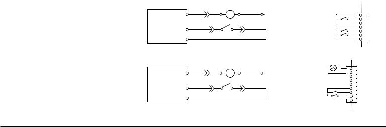
Meat Probe
J5 |
WRC RIGHT |
1 |
PWR J4-1 |
|
|
|
ID J4-2 |
|
DATA J4-3 |
|
GND J4-4 |
WRC LEFT |
J5 |
Meat Probe |
PWR J4-1 |
1 |
|
ID J4-2 |
|
|
DATA J4-3 |
|
|
GND J4-4 |
|
|
20
Test Name |
Description |
Steps |
|
TEST #5 |
To check: RTD function is good. |
1. |
Unplug range or disconnect power. |
RTD Main Oven |
Examples: |
2. |
Remove door and toe panel to access main control. |
Temperature |
3. |
Verify that ALL connectors are inserted all the way into the main control. |
|
Sensor |
1. F6E1 |
4. |
Check connector P10 on the main control ACU board. Make sure it is plugged in and fully |
|
2. No heating (as temperature |
||
|
|
seated. |
|
|
“reaches”) |
|
If it is not, make the proper connection and go to step 8. |
|
|
5. |
Disconnect the P10 connector and measure indicated temperature sensor resistance value of the |
|
|
|
RTD from P10-1 and P10-2 from the harness side. The resistance values should read: |
|
|
|
Oven Sensor(s) - Between 931 and 2869 Ω (approximately 1080 Ω at room temperature). |
|
|
|
If the temperature sensor does meet the requirements, go to step 8. |
|
|
6. |
Remove back panels and ensure the indicated temperature sensor is plugged in properly and |
|
|
|
fully inserted. See “Component Locations” section. |
|
|
|
If it is not, plug it into the connector and go to step 8. |
|
|
7. |
Disconnect the RTD from the main harness and measure resistance from the RTD connector. The |
Right Temp Sensor |
|
|
VT |
P10-1 |
|
VT |
||
P10-2 |
||
|
resistance values should read Oven Sensor(s) - Between 931 and 2869 Ω (approximately 1080 Ω at room temperature).
If it is out of range, the oven sensor is improperly functioning, and needs to be replaced.
8.Reassemble all parts and panels. Plug in range or reconnect power.
9.Wait 3 minutes before checking if there is an error.
If there is an error, go to service mode to check if the error code is F6E1 (Main Oven Over Temperature Limit).
21

FOR SERVICE TECHNICIAN’S USE ONLY
Test Name |
Description |
Steps |
|
|
|
|
|
TEST #6 |
To check: RTD function is good. |
1. |
Unplug range or disconnect power. |
RTD Left Oven |
|
2. |
Remove door and toe panel to access main control. |
Temperature |
Example: |
3. |
Verify that ALL connectors are inserted all the way into the main control. |
Sensor |
■■ F6E3 |
4. |
Check connector J3 on the left control REB board. Make sure it is plugged in and fully seated. |
If it is not, make the proper connection and go to step 8.
5.Disconnect the J3 connector and measure indicated temperature sensor resistance value of the RTD from J3-1 and J3-2 from the harness side. The resistance values should read: Oven Sensor(s) - Between 931 and 2869 Ω (approximately 1080 Ω at room temperature).
If the temperature sensor does meet the requirements, go to step 8.
6.Remove back panels and ensure the indicated temperature sensor is plugged in properly and fully inserted. See “Component Locations” section.
If it is not, plug it into the connector and go to step 8.
Left Temp Sensor |
J3 |
|
|
|
1 |
Strobe |
|
Door Switch |
|
Pressure switch |
|
7.Disconnect the RTD from the main harness and measure resistance from RTD connector. The resistance values should read: Oven Sensor(s) - Between 931 and 2869 Ω (approximately 1080 Ω at room temperature).
If it’s out of range, the oven sensor is improperly functioning, and needs to be replaced.
8.Reassemble all parts and panels. Plug in range or reconnect power.
9.Wait 3 minutes before checking if there is an error.
If there is an error, go to service mode to check if the error code is F6E3 (Left Oven Over Temperature Limit).
22
Test Name |
Description |
Steps |
|||
TEST #7 |
Examples: |
1. |
Unplug range or disconnect power. |
||
Meat Probe & |
1. |
F3E3 |
2. |
Open console assembly to access the user interface. |
|
Jack or Main |
2. |
F3E9 |
3. |
Verify that all connectors are inserted all the way into the user interface board(s). |
|
Oven Meat Probe |
3. |
Can’t start meat probe cycle. |
4. Check resistance of meat probe sensor, the resistance should read between 3,400 and 39,500 Ω. |
||
Short-Circuit |
|||||
|
|
|
If it is out of range, the meat probe is improperly functioning. Replace probe and go to step 6. |
||
Meat Probe & |
|
|
|
||
|
|
5. |
Check connector J5 on the user interface board. Make sure it is plugged in and fully seated. |
||
Jack or Left |
|
|
|||
|
|
|
If it is not, make the proper connection and go to step 6. |
||
Oven Meat Probe |
|
|
|
||
|
|
6. |
Disconnect J5 connector from the user interface board. Measure resistance between J5-1 and |
||
Short-Circuit |
|
|
|||
|
|
|
|
J5-2 and it should be open. |
|
|
|
|
|
If it short-circuit, the user interface board is improperly functioning, change the user interface |
|
|
|
|
|
board and go to step 7. |
|
|
|
|
7. |
Insert meat probe into meat probe Jack. Disconnect the J5 connector and measure indicated |
|
|
|
|
|
meat probe sensor resistance value from J5-1 and J5-2 from the harness side. The resistance |
|
|
|
|
|
values should read between 3,400 and 39,500 Ω. |
|
|
|
|
|
If the temperature sensor does meet the requirements, go to step 10. |
|
|
|
|
8. |
Remove back panels and ensure the indicated meat probe jack harness is plugged in properly |
|
|
|
|
|
and fully inserted. See “Component Locations” section. |
|
|
|
|
|
If it is not, plug it into the connector and go to step 10. |
|
Meat Probe
J5 |
WRC RIGHT |
1 |
PWR J4-1 |
|
|
|
ID J4-2 |
|
DATA J4-3 |
|
GND J4-4 |
WRC LEFT |
J5 |
Meat Probe |
PWR J4-1 |
1 |
|
ID J4-2 |
|
|
DATA J4-3 |
|
|
GND J4-4 |
|
|
9.Disconnect the meat probe jack cable from the main harness and measure resistance from probe jack connector. The resistance values should read between 3,400 and 39,500 Ω.
If it’s out of range, check meat probe jack cable. If it is improperly functioning.
10.Reassemble all parts and panels. Plug in range or reconnect power. Use the app to start a meat probe cycle (meat probe cycle can only start from the app).
11.Wait 3 minutes before checking if there is an error.
If there is an error, go to service mode or use the app to check if the error code is F6E3 (main oven meat probe short-circuit) or F6E9 (left oven meat probe short-circuit).
23

FOR SERVICE TECHNICIAN’S USE ONLY
Test Name |
Description |
Steps |
||
TEST #8 |
Check the door switch detection |
1. |
Unplug range or disconnect power. |
|
Door Switch(es) |
function is good. |
2. |
Wait 10 seconds then plug in range or reconnect power. |
|
|
Examples: |
3. |
Wait for 20 seconds. Open the oven door. Move the knob to clean & clean positions, press the |
|
|
|
start button. There should be no response (no tone, no start button light change) or start light |
||
|
1. |
F5E0 |
|
|
|
|
keeps slow flashing. |
||
|
2. |
F5E2 |
|
If there is a tone response, and the latch motor starts operation, go to step 5. |
4.Move the knob to the Bake and Off positions. Close the door. Move the knob to clean & clean position and press the start button. Check if the latch motor is functioning.
If there is a tone response, and the latch motor starts operation, the door switch test is passed.
5.Unplug range or disconnect power.
6.Remove the door and toe panel to access the main control.
7.Verify that ALL connectors are inserted all the way into the main control.
8.Use a multimeter to measure the resistance of the door switch input. For the main cavity door switch, the inputs are P7-4 & P7-5 from the main ACU.
For the left cavity switch, the inputs are J3-6 & J3-7 from the left control board REB.
It should be open when the door is open and it should be shorted when the door is closed or when the door switch is manually pressed and held.
If the resistance is correct, replace ACU or REB control. Reassemble all parts and panels. Plug in range or reconnect power and go to step 1 to verify the door switch function again.
9.Remove back panel, check continuity of the door switch and electrical connections between the control board and switch.
If continuity is not present, go to step 10.
10.Replace door latch motor assembly.
11.Reassemble all parts and panels. Plug in range or reconnect power and go to step 1 to verify the door switch function again.
HES Signal GND
Door Latch Switch Right
HES Signal
Strobe
Door Switch
Door Latch Switch Left
HES Signal VDD
Left Temp Sensor |
J3 |
|
|
P7 |
1 |
|
|
1 |
|
Strobe |
J3-6 |
Door Switch |
J3-7 |
Pressure switch |
|
24

Test Name |
Description |
Steps |
||
TEST #9 |
Latch switch or motor |
1. |
Unplug range or disconnect power. |
|
Door Lock Motor |
|
|
2. |
Remove door and toe panel to access main control. |
and Door Latch |
Examples: |
3. |
Verify that ALL connectors are inserted all the way into the main control. |
|
Switch |
1. |
F5E0 |
4. |
Connect AC voltmeter to P5-6 (L1 to Latch Motor) and P6-5 (N) for main cavity or between P5-7 |
|
2. |
F5E1 |
|
(L1 to Latch Motor) and P6-5 (N) for left cavity latch motor. |
|
3. |
F5E2 |
5. |
Plug in range or reconnect power. |
|
4. |
F5E3 |
6. |
Close the door or press and hold the door switch. Move the knob to clean & clean positions, |
|
NOTE: Run TEST #8 to ensure the |
|
press the start button. Wait and check if the door can be latched and monitor the AC voltage. |
|
|
door switch function is functional |
|
If the door is latched and the heater starts, the lock motor and latch switch functions are good. |
|
|
before this test. |
|
Wait 3 minutes before checking if there is an error. |
|
If there is no error, unplug range or disconnect power and go to step 12.
If the door latch motor does not operate or if there is no 120 voltage within 1 minute, unplug range or disconnect power and go to step 7.
If the door latch motor operates but motor keeps operating after 1 minute, unplug range or disconnect power and go to step 7.
7.If 120 VAC is not presented, check AC voltage between P5-9 (L1 input to relay) and P6-5 (N). If 120 VAC is presented, the main control (ACU) is improperly functioning. Unplug range or disconnect power, go to step 11.
8.Unplug range or disconnect power. Check continuity of P5-9 (L1) to L1 pin in power cord. Ensure no wires are pinched or damaged.
If the wiring is damaged, replace main harness and go to step 12.
9.Check continuity of the latch motor and electrical connections between the main control ACU P5-6 for main cavity or P5-7 for left cavity and motors. Ensure no wires are pinched or damaged. If the wiring id is damaged, replace main harness or door latch harness and go to step 12.
10.Checking continuity of the latch switch and electrical connections between the main control ACU P7-2, P7-6 and the main cavity door switch or between control ACU P7-4, P7-6 and the left cavity door switch. Ensure no wires are pinched or damaged.
If the wiring is damaged, replace door latch switch harnesses or main harness and go to step 12.
25
FOR SERVICE TECHNICIAN’S USE ONLY
Test Name |
Description |
Steps |
|
TEST #9 |
|
11. |
Replace main control ACU. |
(Continued) |
|
12. |
Reassemble all parts and panels. Plug in range or reconnect power. Go to step 4 to repeat the |
|
|
|
test. |
|
L1 output |
|
|
|
|
|
|
|
BK |
|
M |
WH |
P6_5 |
HES Signal GND |
P7 |
P5-6 |
|
1 |
|||||
|
|
N |
|||||
|
|
|
|
|
|
Door Latch Switch Right |
|
Main |
YL |
YL |
GY |
|
|
HES Signal |
|
P7-2 |
|
|
Strobe |
|
|||
|
|
|
|
|
Door Switch |
|
|
|
|
|
|
|
|
|
|
P7-4 |
GY |
|
|
|
|
Door Latch Switch Left |
|
|
|
|
|
HES Signal VDD |
|
||
|
|
|
|
|
|
|
|
|
L1 output |
|
|
|
|
Left Temp Sensor |
J3 |
|
BK |
|
M |
WH |
P6_5 |
|
1 |
P5-7 |
|
|
|
||||
|
|
N |
|
|
|||
Left |
YL |
YL |
GY |
|
|
Strobe |
|
P7-6 |
|
|
J3-6 |
||||
|
|
|
|
|
|||
|
GY |
|
|
|
|
Door Switch |
J3-7 |
P7-4 |
|
|
|
|
Pressure switch |
|
26
Test Name |
Description |
Steps |
|
TEST #10 |
Control, fan, HE sensor |
1. |
Unplug range or disconnect power. Measure the cooling fan connection on the main control |
Main Oven (Right) |
|
|
ACU. Measure the low and high speed resistance values and compare to expected values. |
Cooling Fan |
This test measures the function |
|
High Speed between J6-4 and J5-3 and compare to High Speed Resistance (21±5 Ω). |
|
of the cooling fan including the |
|
Low Speed resistance between J7-2 and J5-3 and compare to Low Speed Resistance (29±5 Ω). |
|
resistance at low and high speed to |
|
If both low and high resistance values are within range, then go to step 5. If either are out of |
|
determine if there is a connection |
|
range, go to step 2. |
|
or fan motor issue. Additionally, it |
2. |
Remove back panel, check the connection to the cooling fan, and measure resistance on cooling |
|
provides a method to test the hall |
|
fan connector. High Speed Resistance should be present between black and white wire and Low |
|
effect sensor feedback. |
|
Speed Resistance should be present between red and white. If not present, replace the cooling |
|
Resistance Tests: |
|
fan. |
|
3. |
Remove J5 connector, measure resistance on the board between J5-2 and J5-3 (hall effect |
|
|
1. High/low speed cooling fan - |
||
|
|
sensor feedback circuit), if the resistance is out of 5~10 KΩ, replace REB control. |
|
|
motor check |
4. |
Reconnect all connectors. |
|
2. Hall sensor feedback circuits in |
||
|
5. |
Connect voltmeter between J5-2 (GND) and J5-3 (VDD). Plug in range or reconnect power and |
|
|
board - circuit/connection |
||
|
|
measure DC voltage. If VDD 12~15V is present, unplug range or disconnect power and go to |
|
|
|
|
|
|
Function Tests: |
|
step 8. |
|
6. |
Unplug range or disconnect power. Disconnect J5 and plug in range or reconnect power to |
|
|
1. High speed cooling fan - |
||
|
|
measure DC voltage again. If it is still not present, REB is improperly functioning. Unplug range or |
|
|
mechanical or other failure |
|
disconnect power and replace REB board. |
|
2. Hall effect sensor - determine if |
7. |
Unplug range or disconnect power. Disconnect J3 to open the RTD in order to test the cooling |
|
sensor failed |
|
fan. |
|
3. Low speed cooling fan - |
|
NOTE: This will trigger an RTD error code F3E1 but it is necessary to isolate and test the cooling |
|
mechanical or other failure |
|
fan. |
|
|
|
Plug in range or reconnect power. The high speed cooling fan should turn on immediately. Check |
|
|
|
visually to see if the fan is on. If it is on, wait for 3 minutes, then unplug range or disconnect |
|
|
|
power and go to step 10. Otherwise, unplug range or disconnect power and proceed to step 8. |
|
|
8. |
If the cooling fan is not on, connect the voltmeter between J6-4 and J5-3. Plug in range or |
|
|
|
reconnect power and measure AC voltage. If 120 VAC is not present, unplug range or disconnect |
|
|
|
power and replace REB control. |
|
|
9. |
If 120 VAC is present, unplug range or disconnect power and connect voltmeter between the |
|
|
|
black wire and white wire on the cooling fan. Plug in range or reconnect power, if 120 VAC |
|
|
|
is present, but the fan is not on, the cooling fan is improperly functioning. Unplug range or |
|
|
|
disconnect power. |
|
|
|
|
27
FOR SERVICE TECHNICIAN’S USE ONLY
Test Name |
Description |
Steps |
|
|
|
|
|
TEST #10 |
|
10. If the cooling fan is on but the error is still occurring, reassemble all parts and panels. Plug in |
|
(Continued) |
|
|
range or reconnect power and enter diagnostic mode to check if it is the same cooling fan error |
|
|
|
code F8E1 (low speed error) or F8E2 (high speed error). If there are no cooling fan errors (F8E0 or |
|
|
|
F8E2), go to step 11. |
|
|
11. |
Go to the service diagnostics manual test mode to turn on the low speed cooling fan. Visually |
|
|
|
check and if fan is on, go to step 14. |
|
|
12. |
If the cooling fan is not on, unplug range or disconnect power. Connect a voltmeter between |
|
|
|
P6-4 and J5-2, plug in range or reconnect power and measure AC voltage. |
|
|
|
If 120 VAC is not present, unplug range or disconnect power and replace the REB control. |
|
|
13. |
If 120 VAC is present, unplug range or disconnect power. Connect voltmeter between the black |
|
|
|
wire and white wire on the cooling fan. Plug in range or reconnect power and measure AC |
|
|
|
voltage. |
|
|
|
If 120 VAC is present, but the fan is not on, cooling fan is improperly functioning. Unplug range or |
|
|
|
disconnect power. |
|
|
14. |
After replacing components, run step 7 again to ensure the issue has been fixed. |
|
|
15. |
Reassemble all parts and panels. Plug in range or reconnect power. |
|
|
|
|
28

Test Name |
Description |
Steps |
|
TEST #11 |
Control, fan, HE sensor |
1. |
Unplug range or disconnect power. Measure the cooling fan connection on the left cavity control |
Secondary (Left) |
This test measures the function |
|
REB. Measure the low and high speed resistance values and compare to expected values. |
Oven Cooling Fan |
of the cooling fan including the |
|
High Speed between J6-4 and J5-3 and compare to High Speed Resistance (21±5 Ω). |
|
resistance at low and high speed to |
|
Low Speed resistance between J7-2 and J5-3 and compare to Low Speed Resistance (29±5 Ω). |
|
determine if there is a connection |
|
If both low and high resistance values are within range, then go to step 5. If either are out of |
|
or fan motor issue. Additionally, it |
2. |
range, go to step 2. |
|
provides a method to test the hall |
Remove back panel, check the connection to the cooling fan, and measure resistance on cooling |
|
|
effect sensor feedback. |
|
fan connector. High Speed Resistance should be present between black and white wire and Low |
|
Resistance Tests: |
|
Speed Resistance should be present between red and white. If not present, change cooling fan. |
|
3. |
Remove J5 connector, measure resistance on the board between J5-2 and J5-3 (hall effect |
|
|
1. High/low speed cooling fan - |
||
|
|
sensor feedback circuit), if the resistance is out of 5~10 KΩ, replace REB control. |
|
|
motor check |
|
|
|
4. |
Reconnect all connectors. |
|
|
2. Hall sensor feedback circuits in |
||
|
5. |
Connect voltmeter between J5-2 (GND) and J5-3 (VDD). Plug in range or reconnect power and |
|
|
board - circuit/connection |
||
|
|
measure DC voltage. |
|
|
Function Tests: |
|
|
|
|
If VDD 12~15 V is present, unplug range or disconnect power and go to step 8. |
|
|
1. High speed cooling fan - |
|
|
|
6. |
Unplug range or disconnect power. Disconnect J5, plug in range or reconnect power and |
|
|
mechanical or other failure |
||
|
|
measure DC voltage again. If it is still not present, REB is improperly functioning. Unplug range or |
|
|
2. Hall effect sensor - determine if |
|
|
|
|
disconnect power and replace REB board. |
|
|
sensor failed |
7. |
Unplug range or disconnect power. Disconnect J3 to open the RTD in order to test the cooling |
|
3. Low speed cooling fan - |
||
|
|
fan. |
|
|
mechanical or other failure |
|
NOTE: This will trigger an RTD error code F3E1 but it is necessary to isolate and test the cooling |
|
|
|
fan. |
|
|
|
Plug in range or reconnect power, The high speed cooling fan should turn on immediately. |
|
|
|
Visually check if the fan is on. If it is on, unplug range or disconnect power and wait for 3 |
|
|
|
minutes, then go to step 10. Otherwise, proceed to step 8. |
|
|
8. |
If the cooling fan is on, unplug range or disconnect power and connect the voltmeter between |
|
|
|
J6-4 and J5-3. Plug in range or reconnect power and measure AC voltage. |
|
|
|
If 120 VAC is not present, unplug range or disconnect power and replace REB control. |
|
|
9. |
If 120 VAC is present, unplug range or disconnect power. Connect voltmeter between black wire |
|
|
|
and white wire on the cooling fan, plug in range or reconnect power. |
If 120 VAC is present but the fan is not on, the cooling fan is improperly functioning. Unplug range or disconnect power.
29
 Loading...