


INSTALLATION INSTRUCTIONS
30" (76.2 CM), 36" (91.4 CM) AND 48" (121.9 CM) PRO-STYLE® GAS CONVECTION RANGES
for residential use only
INSTRUCTIONS D’INSTALLATION
CUISINIÈRES À CONVECTION -
À GAZ PRO-STYLE® DE 30" (76,2 CM), 36" (91,4 CM)
ET 48" (121,9 CM)
pour utilisation résidentielle uniquement
Table of Contents/Table des matières
RANGE SAFETY.......................................................................... |
2 |
INSTALLATION REQUIREMENTS............................................. |
3 |
Tools and Parts......................................................................... |
3 |
Location Requirements ............................................................ |
4 |
Electrical Requirements............................................................ |
6 |
Gas Supply Requirements........................................................ |
6 |
INSTALLATION INSTRUCTIONS............................................... |
8 |
Unpack Range .......................................................................... |
8 |
Install Anti-Tip Bracket ............................................................. |
8 |
Make Gas Connection.............................................................. |
9 |
Verify Anti-Tip Bracket Location............................................. |
10 |
Level Range ............................................................................ |
10 |
Install Griddle .......................................................................... |
10 |
Electronic Ignition System ...................................................... |
11 |
Reinstall Kick Plate ................................................................. |
12 |
Complete Installation.............................................................. |
12 |
GAS CONVERSIONS ................................................................ |
13 |
LP Gas Conversion................................................................. |
13 |
Natural Gas Conversion ......................................................... |
21 |
Wiring Diagrams ..................................................................... |
29 |
Strip Circuits ........................................................................... |
31 |
SÉCURITÉ DE LA CUISINIÈRE................................................ |
34 |
EXIGENCES D'INSTALLATION................................................ |
35 |
Outils et pièces ....................................................................... |
35 |
Exigences d’emplacement ..................................................... |
36 |
Spécifications électriques....................................................... |
38 |
Spécifications de l'alimentation en gaz.................................. |
39 |
INSTRUCTIONS D’INSTALLATION ......................................... |
40 |
Déballage de la cuisinière....................................................... |
40 |
Installation de la bride antibasculement................................. |
41 |
Raccordement au gaz............................................................. |
42 |
Vérification de l'emplacement de la bride antibasculement .. |
42 |
Réglage de l'aplomb de la cuisinière...................................... |
43 |
Installation de la plaque à frire................................................ |
43 |
Système d'allumage électronique .......................................... |
43 |
Réinstallation du garde-pieds................................................. |
45 |
Achever l’installation ............................................................... |
45 |
CONVERSIONS POUR CHANGEMENT DE GAZ ................... |
46 |
Conversion pour l'alimentation au propane ........................... |
46 |
Conversion pour l'alimentation au gaz naturel....................... |
55 |
Schémas de câblage .............................................................. |
63 |
Schémas des circuits.............................................................. |
65 |
IMPORTANT:
Save for local electrical inspector's use.
Installer: Leave installation instructions with the homeowner. Homeowner: Keep installation instructions for future reference.
IMPORTANT :
À conserver pour consultation par l'inspecteur local des installations électriques. Installateur : Remettre les instructions d'installation au propriétaire. Propriétaire : Conserver les instructions d'installation pour référence ultérieure.
W10526092B
RANGE SAFETY
Your safety and the safety of others are very important.
We have provided many important safety messages in this manual and on your appliance. Always read and obey all safety messages.
This is the safety alert symbol.
This symbol alerts you to potential hazards that can kill or hurt you and others.
All safety messages will follow the safety alert symbol and either the word “DANGER” or “WARNING.” These words mean:
 DANGER
 WARNING
You can be killed or seriously injured if you don't immediately follow instructions.
You can be killed or seriously injured if you don't follow instructions.
All safety messages will tell you what the potential hazard is, tell you how to reduce the chance of injury, and tell you what can happen if the instructions are not followed.
WARNING: If the information in this manual is not followed exactly, a fire or explosion may result causing property damage, personal injury or death.
–Do not store or use gasoline or other flammable vapors and liquids in the vicinity of this or any other appliance.
–WHAT TO DO IF YOU SMELL GAS:
•Do not try to light any appliance.
•Do not touch any electrical switch.
•Do not use any phone in your building.
•Immediately call your gas supplier from a neighbor's phone. Follow the gas supplier's instructions.
•If you cannot reach your gas supplier, call the fire department.
–Installation and service must be performed by a qualified installer, service agency or the gas supplier.
WARNING: Gas leaks cannot always be detected by smell.
Gas suppliers recommend that you use a gas detector approved by UL or CSA.
For more information, contact your gas supplier.
If a gas leak is detected, follow the “What to do if you smell gas” instructions.
IMPORTANT: Do not install a ventilation system that blows air downward toward this gas cooking appliance. This type of ventilation system may cause ignition and combustion problems with this gas cooking appliance resulting in personal injury or unintended operation.
2
In the State of Massachusetts, the following installation instructions apply:
■Installations and repairs must be performed by a qualified or licensed contractor, plumber, or gasfitter qualified or licensed by the State of Massachusetts.
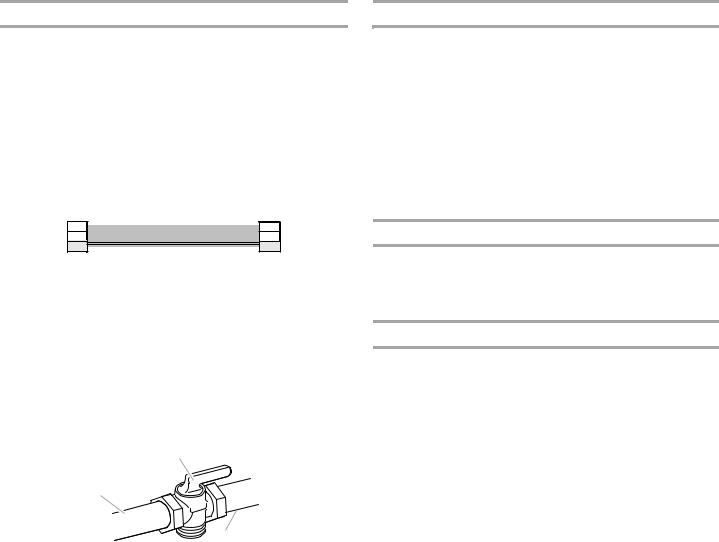
■If using a ball valve, it shall be a T-handle type.
■A flexible gas connector, when used, must not exceed 3 feet.
|
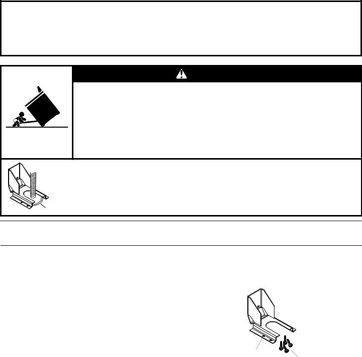
WARNING |
|
Tip Over Hazard |
A child or adult can tip the range |
killed. |
Install anti-tip bracket to floor or |
installation instructions. |
Slide range back so rear range foot is engaged in the slot of the anti-tip bracket.
Re-engage anti-tip bracket if range is moved.
Do not operate range without anti-tip bracket installed and engaged.
Failure to follow these instructions can result in death or serious burns to children and adults.
Anti-Tip
 Bracket
Range Foot
To verify the anti-tip bracket is installed and engaged:
•Slide range forward.
•Look for the anti-tip bracket securely attached to floor or wall.
•Slide range back so rear range foot is under anti-tip bracket.
•See installation instructions for details.
INSTALLATION REQUIREMENTS
Tools and Parts
Gather the required tools and parts before starting installation. Read and follow the instructions provided with any tools listed here.
Tools needed
■ |
Tape measure |
■ |
³⁄" carbide tip masonry bit |
■ |
#2 Phillips screwdriver |
■ |
Marker or pencil |
■ |
¹⁄" x 4¼" flat-blade |
■ |
Pipe-joint compound |
|
screwdriver |
|
resistant to LP gas |
■ |
Level |
■ |
Noncorrosive leak-detection |
■ |
Drill |
|
solution |
|
Tubing cutter |
||
■ |
Wrench or pliers |
■ |
|
|
|
■ |
Pipe wrench |
For LP/Natural Gas |
||
■ |
Adjustable wrench or |
Conversions |
||
■ |
Adjustable wrench |
|||
|
⁄" wrench |
|||
|
|
|
||
■ |
³⁄" drive ratchet |
■ ½" deep-well socket |
||
|
|
|||
■ |
¹⁄" drill bit |
■ 7 mm nut driver |
||
|
|
|||
■ |
¹ ⁄" combination wrench |
■ |
Masking tape |
|
|
|
|||
■¹⁄", ³⁄", ⁄" nut drivers
Parts supplied
Check that all parts are included.
■Anti-tip bracket kit
A
B
A.Anti-tip bracket
B.#8-18 x 1" Phillips head screws (4)
NOTE: Anti-tip bracket must be securely mounted to subfloor. Thickness of flooring may require longer screws to anchor bracket to subfloor. Longer screws are available from your local hardware store. See “Install Anti-Tip Bracket” section.
■Gas pressure regulator
■Burner grates
■Burner bases and burner caps
■Griddle drip tray (on griddle models)
■LP orifice package (W10393336)
■Conversion label (8114P522-60)
NOTE: The cooktop is manufactured for use with Natural gas. To convert to LP gas, see the “Gas Conversions” section.
3

Parts needed
All models must be installed with a backguard if installing at zero clearance to a combustible backwall. See “Cabinet Dimensions” in the “Location Requirements” section for installation requirements.
■30" (76.2 cm) Adjustable Backguard Order Part Number 8285148
■36" (91.4 cm) Adjustable Backguard Order Part Number 8284756
■48" (121.9 cm) Adjustable Backguard Order Part Number 8284755
■22" (55.9 cm) Backsplash with Dual-Position Shelf for 30"(76.2 cm) Ranges
Order Part Number W10285447
■22" (55.9 cm) Backsplash with Dual-Position Shelf for 36" (91.4 cm) Ranges
Order Part Number W10285448
■22" (55.9 cm) Backsplash with Dual-Position Shelf for 48" (121.9 cm) Ranges
Order Part Number W10285449
To order, see the “Assistance or Service” section of the Use and Care Guide.
Check local codes and consult gas supplier. Check existing gas supply and electrical supply. See “Electrical Requirements” and “Gas Supply Requirements” sections.
It is recommended that all electrical connections be made by a licensed, qualified electrical installer.
High Altitude Conversion
To convert the range for elevations above 6,560 ft (1999.5 m), order a High Altitude Conversion Kit.
■Part Number W10394294 - LP high altitude
■Part Number W10394293 - Natural gas high altitude
To order, see the “Assistance or Service” section of the Use and Care Guide.
Location Requirements
IMPORTANT: Observe all governing codes and ordinances. Do not obstruct flow of combustion and ventilation air.
■It is the installer’s responsibility to comply with installation clearances specified on the model/serial rating plate. The model/serial rating plate is located under the console on the right-hand side.
■It is recommended that a 600 CFM or larger range hood be installed above the range.
■It is not recommended that a microwave hood combination be mounted above the range.
■Recessed installations must provide complete enclosure of the sides and rear of the range.
■To eliminate the risk of burns or fire by reaching over heated surface units, cabinet storage space located above the surface units should be avoided. If cabinet storage is to be provided, the risk can be reduced by installing a range hood that projects horizontally a minimum of 5" (12.7 cm) beyond the bottom of the cabinets.
■All openings in the wall or floor where range is to be installed must be sealed.
■Do not seal the range to the side cabinets.
■Cabinet opening dimensions that are shown must be used. Given dimensions are minimum clearances.
■The anti-tip bracket must be installed. To install the anti-tip bracket shipped with the range, see “Install Anti-Tip Bracket” section.
■Grounded electrical supply is required. See “Electrical Requirements” section.
■Proper gas supply connection must be available. See “Gas Supply Requirements” section.
■Contact a qualified floor covering installer to check that the floor covering can withstand at least 200°F (93°C). Use an insulated pad or ¼" (0.64 cm) plywood over carpet and under range if installing range over carpeting.
IMPORTANT: To avoid damage to your cabinets, check with your builder or cabinet supplier to make sure that the materials used will not discolor, delaminate or sustain other damage. This oven has been designed in accordance with the requirements of UL and CSA International and complies with the maximum allowable wood cabinet temperatures of 194°F (90°C).
Mobile Home - Additional Installation Requirements
The installation of this range must conform to the Manufactured Home Construction and Safety Standard, Title 24 CFR, Part 3280 (formerly the Federal Standard for Mobile Home Construction and Safety, Title 24, HUD Part 280). When such standard is not applicable, use the Standard for Manufactured Home Installations, ANSI A225.1/NFPA 501A or with local codes.
In Canada, the installation of this range must conform with the current standards CAN/CSA-A240-latest edition, or with local codes.
Mobile home installations require:
■When this range is installed in a mobile home, it must be secured to the floor during transit. Any method of securing the range is adequate as long as it conforms to the standards listed above.
Product Dimensions
30" (76.2 cm) models
A
B
C
E
D
A.Island trim
B.27¾" (70.5 cm) depth with control panel, see NOTE*
C.35¾" (89.6 cm) cooktop height when setting on the wheels
D.30" (76.2 cm) width
E.Model/serial rating plate location
4
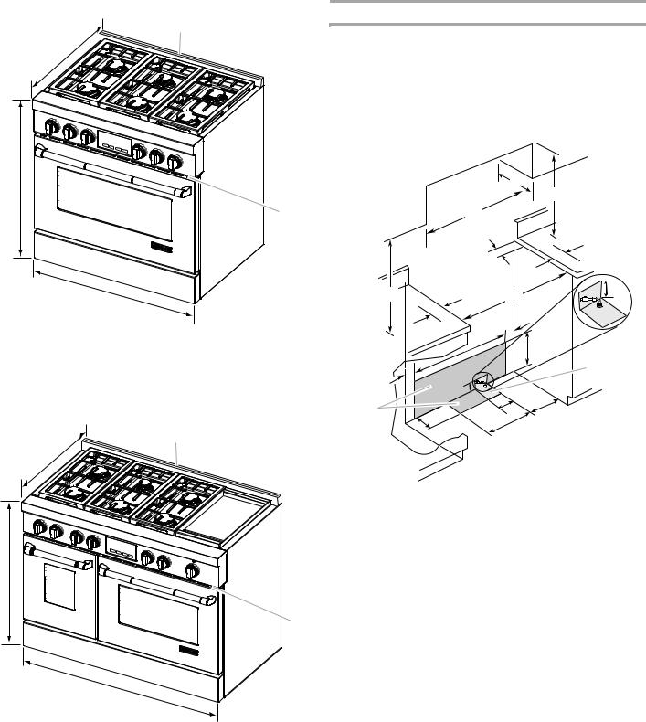
36" (91.4 cm) models
Cabinet Dimensions
A
 Cabinet opening dimensions shown are for 25" (64 cm) B countertop depth, 24" (61 cm) base cabinet depth and
36" (91.4 cm) countertop height. Dimensions must be met in order to ensure a flush fit to backwall.
IMPORTANT: If installing with a range hood or hood liner above the range, follow the range hood or hood liner installation instructions for dimensional clearances above the cooktop surface.
C |
|
C |
|
|
D ** |
E |
B |
|
|
O*** |
F |
D |
A |
J |
E |
||
|
F |
|
A. Island trim |
|
I |
|
B. 27¹⁄ " (68.9 cm) depth with control panel, see NOTE* |
H |
G |
|
C. 35¾" (90.2 cm) cooktop height when setting on the wheels |
|
Gas |
|
|
installation |
||
D. 36" (91.4 cm) width |
I |
||
area |
|||
E. Model/serial rating plate location |
J |
|
|
|
|
48" (121.9 cm) models |
Electrical |
L |
N |
|
installation |
||||
|
K |
|
||
|
area* |
M |
|
A
B
C
E
D
A.Island trim
B.27¹⁄ " (68.9 cm) depth with control panel, see NOTE*
C.35¾" (90.2 cm) cooktop height when setting on the wheels
D.48" (121.9 cm) width
E.Model/serial rating plate location
*NOTE: When installed in a 24" (61.0 cm) base cabinet with 25" (63.5 cm) countertop; front of oven door protrudes 1⁄" (4.8 cm) beyond 24" (61.0 cm) base cabinet.
A.18" (45.7 cm) upper cabinet to countertop
B.30" (76.2 cm) model: 30" (76.2 cm) min. upper cabinet width 36" (91.4 cm) model: 36" (91.4 cm) min. upper cabinet width 48" (121.9 cm) model: 48" (121.9 cm) min. upper cabinet width
C.13" (33 cm) max. upper cabinet depth
D.For minimum clearance to top of range, see NOTE**.
E.30¼" (76.8 cm) on 30" (76.2 cm) models 36¼" (92.1 cm) on 36" (91.4 cm) models 48¼" (122.6 cm) on 48" (121.9 cm) models
F.6" (15.2 cm) min. clearance from both sides of range to side wall or other combustible material
G.15" (38.1 cm)
H.22" (55.9 cm) on 30" (76.2 cm) models 28" (71.1 cm) on 36" (91.4 cm) models 40" (101.6 cm) on 48" (121.9 cm) models
I.1½" (3.8 cm)
J.3" (7.6 cm)
K.5" (12.7 cm)
L.6" (15.2 cm) on 30" (76.2 cm) models 14" (35.5 cm) on 36" (91.4 cm) models 24" (61.0 cm) on 48" (121.9 cm) models
M.10½" (26.7 cm)
N.6" (15.2 cm)
O.6" (15.2 cm), see NOTE***
5
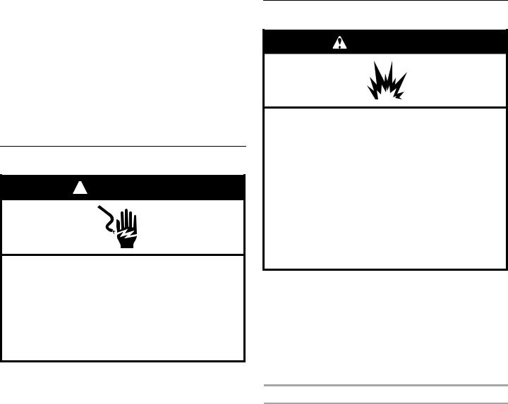
*NOTE: Receptacle must be rotated 90° for Canadian installation.
**NOTE: Minimum Clearances
30" (76.2 cm) models: 30" (76.2 cm) minimum clearance between the top of the cooking platform and the bottom of an uncovered wood or metal cabinet.
36" (91.4 cm) models: 42" (106.7 cm) minimum clearance between the top of the cooking platform and the bottom of an uncovered wood or metal cabinet.
48" (121.9 cm) models: 42" (106.7 cm) minimum clearance between the top of the cooking platform and the bottom of an uncovered wood or metal cabinet.
***NOTE: If backwall is constructed of a combustible material and a backguard is not installed, a 6" (15.2 cm) minimum clearance is required for all models.
Electrical Requirements
 WARNING
Electrical Shock Hazard
Plug into a grounded 3 prong outlet.
Do not remove ground prong.
Do not use an adapter.
Do not use an extension cord.
Failure to follow these instructions can result in death, fire, or electrical shock.
IMPORTANT: The range must be electrically grounded in accordance with local codes and ordinances, or in the absence of local codes, with the National Electrical Code, ANSI/NFPA 70 or Canadian Electrical Code, CSA C22.1.
If codes permit and a separate ground wire is used, it is recommended that a qualified electrical installer determine that the ground path is adequate.
A copy of the above code standards can be obtained from:
National Fire Protection Association
1 Batterymarch Park
Quincy, MA 02169-7471
CSA International
8501 East Pleasant Valley Road
Cleveland, OH 44131-5575
■A 120 volt, 60 Hz., AC only, 15-amp fused, electrical circuit is required. A time-delay fuse or circuit breaker is also recommended. It is recommended that a separate circuit serving only this range be provided.
■Electronic ignition systems operate within wide voltage limits, but proper grounding and polarity are necessary. Check that the outlet provides 120-volt power and is correctly grounded.
■The wiring diagram is located behind the kick plate in a clear plastic bag.
Gas Supply Requirements
WARNING
Use a new CSA |
gas supply line. |
Install a shut-off valve.
Securely tighten all gas connections.
If connected to LP, have a qualified person make sure gas pressure does not exceed 14" (36 cm) water column.
Examples of a qualified person include:
licensed heating personnel,
authorized gas company personnel, and authorized service personnel.
Failure to do so can result in death, explosion, or fire.
Observe all governing codes and ordinances.
IMPORTANT: This installation must conform with all local codes and ordinances. In the absence of local codes, installation must conform with American National Standard, National Fuel Gas Code ANSI Z223.1/NFPA 54 - latest edition or CAN/CGA B149 - latest edition.
IMPORTANT: Range must be connected to a regulated gas supply.
IMPORTANT: Leak testing of the range must be conducted according to the manufacturer’s instructions.
Type of Gas
Natural Gas:
■This range is factory set for use with Natural gas. The model/ serial rating plate located under the console on the right-hand side has information on the types of gas that can be used. If the types of gas listed do not include the type of gas available, check with the local gas supplier.
LP Gas conversion:
Conversion must be done by a qualified service technician.
No attempt shall be made to convert the range from the gas specified on the model/serial rating plate for use with a different gas without consulting the serving gas supplier. To convert to LP gas, use the LP gas conversion kit provided with your range and see the “Gas Conversions” section. The parts for this kit are in the literature package supplied with the range.
6
Gas Supply Line
■Provide a gas supply line of ¾" (1.9 cm) rigid pipe to the range location. A smaller size pipe on longer runs may result in insufficient gas supply. With LP gas, piping or tubing size can be ½" (1.3 cm) minimum. Usually, LP gas suppliers determine the size and materials used in the system.
NOTE: Pipe-joint compounds that resist the action of LP gas must be used. Do not use TEFLON®† tape.
Flexible metal appliance connector:
■If local codes permit, a new CSA design-certified, 4 - 5 ft (122 - 152.4 cm) long, ⁄" (1.6 cm) or
¾" (1.9 cm) I.D., flexible metal appliance connector may be used for connecting range to the gas supply line.
■A ½" (1.3 cm) male pipe thread is needed for connection to the female pipe threads of the inlet to the range pressure regulator.
■Do not kink or damage the flexible metal tubing when moving the range.
■Must include a manual shutoff valve:
The supply line must be equipped with a manual shutoff valve. This valve should be located in the same room but external to the range opening, such as an adjacent cabinet. It should be in a location that allows ease of opening and closing. Do not block access to shutoff valve. The valve is for turning on or shutting off gas to the range.
B
A
C
A.Gas supply line
B.Shutoff valve “open” position
C.To range
†®TEFLON is a registered trademark of E.I. Du Pont De Nemours and Company.
Gas Pressure Regulator
The gas pressure regulator supplied with this range must be used. The inlet pressure to the regulator should be as follows for proper operation:
Natural Gas:
Minimum pressure: 6" (15.2 cm) WCP
Maximum pressure: 14" (35.6 cm) WCP
LP Gas:
Minimum pressure: 11" (27.9 cm) WCP
Maximum pressure: 14" (35.6 cm) WCP
Contact local gas supplier if you are not sure about the inlet pressure.
Burner Input Rating - Altitude
Input ratings shown on the model/serial rating plate are for elevations up to 2,000 ft (609.6 m).
For elevations above 2,000 ft (609.6 m), ratings need to be reduced at a rate of 4% for each 1,000 ft (304.8 m).
Gas Supply Pressure Testing
Gas supply pressure for testing regulator must be at least
1" water column pressure above the manifold pressure shown on the model/serial rating plate.
Line pressure testing above ½ psi gauge (14" WCP)
The range and its individual shutoff valve must be disconnected from the gas supply piping system during any pressure testing of that system at test pressures in excess of ½ psi (3.5 kPa).
Line pressure testing at ½ psi gauge (14" WCP) or lower
The range must be isolated from the gas supply piping system by closing its individual manual shutoff valve during any pressure testing of the gas supply piping system at test pressures equal to or less than ½ psi (3.5 kPa).
7
INSTALLATION INSTRUCTIONS
Unpack Range
WARNING
Excessive Weight Hazard
Use two or more people to move and install range. Failure to do so can result in back or other injury.
1.Remove shipping materials, tape and film from range. Keep shipping pallet under range. Remove oven racks, grates and parts package from inside oven.
2.Remove screws from kick plate.
B
A
A.Kick plate
B.Remove these screws.
3.Push up on kick plate to release plate from shoulder screws.
4.Lay kick plate to the side to avoid scratching the stainless steel.
5.For 48" (121.9 cm) models only, rotate center support counterclockwise off the pallet until it stops.
NOTE: This support is used only for shipping and is not needed for installation.
6.Lay a piece of cardboard from side packing on the floor behind range. Using 2 or more people, firmly grasp each side of range. Lift range up about 3" (8.0 cm) and move it back until range is off shipping pallet. Set range on cardboard to avoid damaging floor.
Install Anti-Tip Bracket
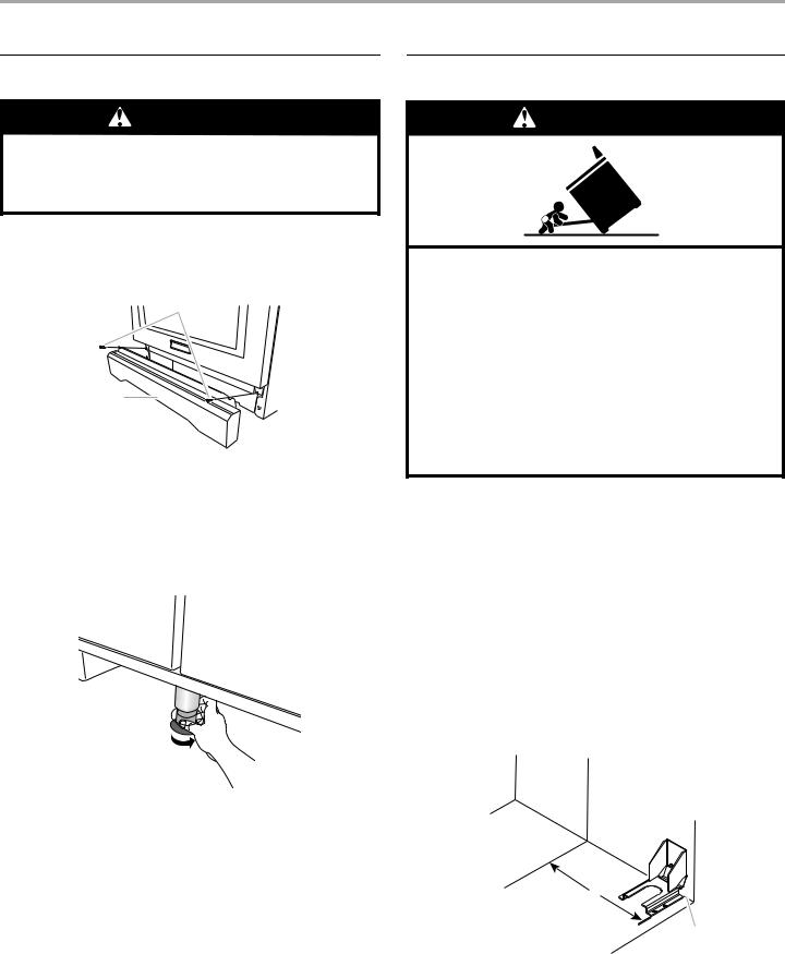
WARNING
Tip Over Hazard
A child or adult can tip the range and be killed.
Install anti-tip bracket to floor or wall per installation instructions.
Slide range back so rear range foot is engaged in the slot of the anti-tip bracket.
Re-engage anti-tip bracket if range is moved.
Do not operate range without anti-tip bracket installed and engaged.
Failure to follow these instructions can result in death or serious burns to children and adults.
1.Determine which mounting method to use: floor or wall.
If you have a stone or masonry floor, you can use the wall mounting method.
2.Determine and mark centerline of the cutout space. The mounting bracket must be installed on the right side of the cutout. Position mounting bracket in cutout as shown in the following illustration.
Measurement B:
30" (76.2 cm) ranges: 11⁄" (29.5 cm) 36" (91.4 cm) ranges: 14⁄" (37.1 cm) 48" (121.9 cm) ranges: 20⁄" (52.4 cm)
Measurement C:
Optional distance from back wall. If back wall is constructed of a combustible material and a backguard is not installed, a 6" (15.2 cm) minimum clearance is required for all models.
Install anti-tip bracket accordingly.
 A
A
B
C
A.Centerline
B.Centerline of cutout to centerline of anti-tip bracket
C.Back wall to back of range
8
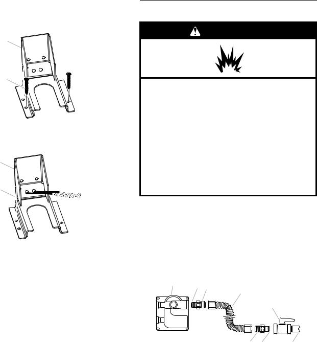
3.Drill two ¹⁄" (3.0 mm) holes that correspond to the bracket holes of the determined mounting method. See the following illustrations.
Floor Mounting
B
A
A.#12 x 1⁄" screws
B.Anti-tip bracket
Wall Mounting
B
A
A.#12 x 1⁄" screws
B.Anti-tip bracket
4.Using a Phillips screwdriver, mount anti-tip bracket to the wall or floor with the two #12 x 1⁄" screws provided.
Depending on the thickness of your flooring, longer screws may be necessary to anchor the bracket to the subfloor. Longer screws are available from your local hardware store.
5.Move range close enough to opening to allow for electrical connections to be made. Remove shipping base, cardboard or hardboard from under range.
6.Continue installing your range using the following installation instructions.
Make Gas Connection
WARNING
Use a new CSA |
gas supply line. |
Install a shut-off valve.
Securely tighten all gas connections.
If connected to LP, have a qualified person make sure gas pressure does not exceed 14" (36 cm) water column.
Examples of a qualified person include:
licensed heating personnel,
authorized gas company personnel, and authorized service personnel.
Failure to do so can result in death, explosion, or fire.
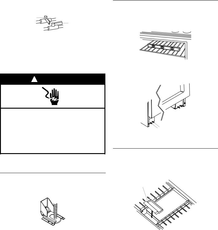
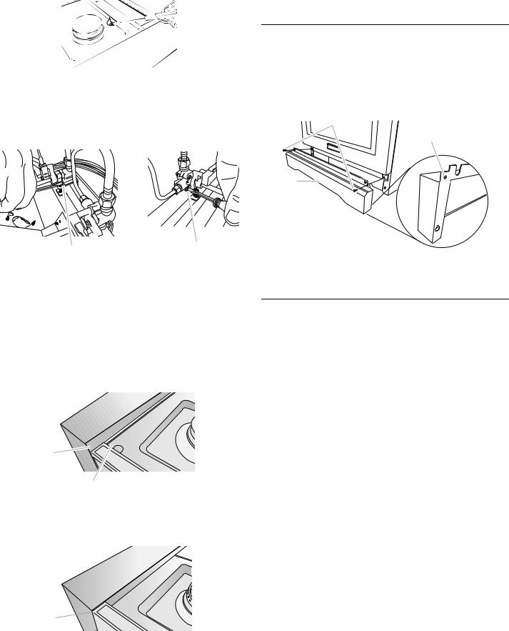
1.Assemble flexible connector from gas supply pipe to pressure regulator located in the middle rear of the range.
2.Apply pipe-joint compound made for use with LP gas to the smaller thread ends of the flexible connector adapters (see B and G in the following illustration).
3.Attach one adapter to the gas pressure regulator and the other adapter to the gas shutoff valve. Tighten both adapters.
4.Use a ¹ ⁄" combination wrench and channel lock pliers to attach the flexible connector to the adapters. Check that connector is not kinked.
A B C
D
E
|
H G |
F |
A. Gas pressure regulator |
E. Manual gas shutoff valve |
|
B. Use pipe-joint compound. |
F. ½" or ¾" gas pipe |
|
C. Adapter (must have ½" male |
G. Use pipe-joint compound. |
|
pipe thread) |
H. Adapter |
|
D. Flexible connector |
|
|
9
Complete Connection
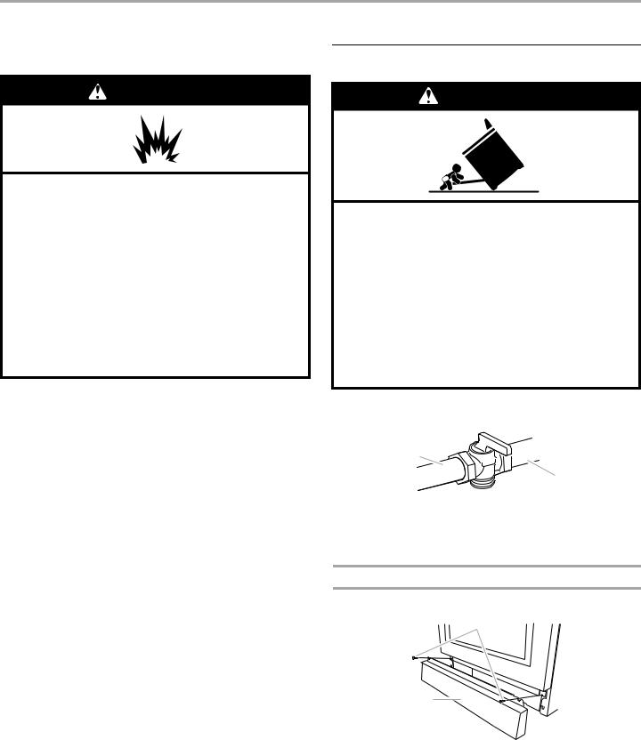
1.Open the manual shutoff valve in the gas supply line. The valve is open when the handle is parallel to the gas pipe.
A
B
A.Closed valve
B.Open valve
2.Test all connections by brushing on an approved noncorrosive leak-detection solution. If bubbles appear, a leak is indicated. Correct any leak found.
3.Remove cooktop burner caps, burner bases and grates from parts package. Place burner bases on cooktop, burner caps on burner bases and place grates over burners and caps.
 WARNING
Electrical Shock Hazard
Plug into a grounded 3 prong outlet.
Do not remove ground prong.
Do not use an adapter.
Do not use an extension cord.
Failure to follow these instructions can result in death, fire, or electrical shock.
4.Plug into a grounded 3 prong outlet.
5.Turn on power supply. For further information, please refer to the user instructions located in the Use and Care Guide.
Verify Anti-Tip Bracket Location
1.Turn all 4 leveling rods 1 full turn to raise the range and provide enough clearance for the rear leveling leg to slide into the anti-tip bracket.
2.Move range into its final location making sure rear leveling leg slides into anti-tip bracket.
3.Use a flashlight to look underneath the bottom of the range and visually check that the rear range foot is inserted into the slot of the anti-tip bracket.
Level Range
NOTE: Range must be level for satisfactory baking performance.
1.Place rack in oven.
2.Place level on rack and check levelness of the range, first side to side; then front to back.
3.If range is not level, adjust the leveling rods. Turn leveling rods located behind the kick plate to level range and to raise or lower range to the desired countertop height.
NOTE: All roller feet must be off the floor upon final installation.
 A
A
B
A
B
A.Front leveling rod
B.Rear leveling rod
Install Griddle
(on griddle models)
The griddle is factory installed.
1.Place drip tray in the well at the front of the griddle. Slide tray toward the back until it stops.
A
B
A.Griddle drip tray
B.Griddle
2.Clean griddle before using. Refer to the Use and Care Guide.
10
Electronic Ignition System
Install Burner Bases and Burner Caps
Install the burner base, making sure the igniter electrode is properly aligned with the base. Place burner caps on top of burner bases. If burner caps are not properly positioned, surface burners will not light.
20,000 Btu/h Ultra Power™ Dual-Flame Burner


 A
A
A. Incorrect
B. Correct
B
15,000 Btu/h Professional Burner
A
A. Incorrect
B. Correct
B
5,000 Btu/h Simmer/Melt Burner
A
A. Incorrect
B. Correct
B
Dual Flame Burner
A
B


A.Upper (simmer) flame
B.Lower flame
Single Flame Burner
To Adjust Flame Height:
1.Unplug range or disconnect power.
2.Remove burner grates.
3.Remove the control knobs.
4.Open the oven door and remove the 2 screws on each side of the range that hold the control console in place.
Initial Lighting and Gas Flame Adjustments
Cooktop burners use electronic igniters in place of standing pilots. When the cooktop control knob is turned to any position, the system creates a spark to light the burner. This sparking continues until the flame is lit or the knob is turned to Off.
Check Operation of Cooktop Burners
Push in and turn each control knob to LITE.
The surface burners and grill flames should light within 4 seconds. The first time a burner is lit, it may take longer than 4 seconds to light because of air in the gas line.
After verifying the proper burner operation, turn the control knobs to OFF.
If burners do not light properly:
■Turn cooktop control knob to OFF.
■Check that the range is plugged in and the circuit breaker has not tripped or the fuse has not blown.
■Check that the gas shutoff valves are set to the “open” position.
■Check that burner caps are properly positioned on burner bases.
Repeat start-up. If a burner does not light at this point, contact your dealer or authorized service company for assistance.
Flame Height
The cooktop flame should be a steady blue flame approximately ¼" (0.64 cm) high.
NOTE: Make sure to leave oven door open or the control console will not rest in the side brackets properly once it is detached.
5.Pull up on the control console and let it drop forward into the notched console brackets on each side.
A
A.Control console bracket
6.Remove the round gasket from the valve stem.
7.Put a control knob onto the valve stem of the burner you want to adjust.
11
8.Turn the control knob to LO and using a butane extension lighter, light the burner.
9.Remove the control knob.
10.Use a ¹⁄" x 4¼" flat-blade screwdriver to adjust the flame height. Tighten screw to reduce flame height. Loosen screw to increase flame height.
NOTE: When you are converting to LP gas, the screw should be tightened down completely on the single output valves. The dual output valve should not be adjusted.
A B
A.Single flame burner adjustment screw (on right side of valve)
B.Dual flame burner adjustment screw (on left side of valve)
11.When finished adjusting the flame height, put a control knob back onto the valve stem and turn off the burner.
12.Remove the control knob.
13.Replace the round gasket.
14.Repeat steps 6 through 13 for any other burners that need adjustment.
15.Lift up on the control console and set it back into place. For a proper fit, the flange of the control console must hook over the lip on the front of the range cooktop.
A
B
A.Control console flange
B.Front lip of range cooktop
16.Check that the control console is flush with the top edge of the range.
A 

A.Flush with range top
17.Replace the 2 screws on each side of the control console.
18.Replace the control knobs.
19.Replace burner grates.
20.Test the flame by turning the control from LO to HI, checking the flame at each setting.
Reinstall Kick Plate
1.Align shoulder screw mounting holes with shoulder screws on range.
2.Push kick plate down against front of range until the top screw holes are aligned with the mounting holes on the front of the range.
3.Reattach screws to the top of the kick plate.
B
C
A
D 
A.Kick plate
B.Reattach these screws.
C.Top screw hole
D.Shoulder screw mounting hole
Complete Installation
1.Check that all parts are now installed. If there is an extra part, go back through the steps to see which step was skipped.
2.Check that you have all of your tools.
3.Dispose of/recycle all packaging materials.
4.For oven use and cleaning, read the Use and Care Guide.
Check Operation of Oven Bake Burner(s)
1.Remove the oven racks and bake burner cover and set them aside on a covered surface.
2.Start a Bake cycle. See the Use and Care Guide for operating instructions.
The oven bake burner should light within 8 seconds. Under certain conditions it may take the burner up to 60 seconds to light.
Electronic igniters are used to light the bake burners.
NOTE: No adjustments can be made to the bake flames.
Check Operation of Oven Broil Burner
1.Remove the oven racks and set them aside on a covered surface.
2.Start a Broil cycle. See the Use and Care Guide for operating instructions.
The oven broil burner should light within 8 seconds. Under certain conditions it may take the burner up to 60 seconds to light.
Electronic igniters are used to light the broil burner.
NOTE: No adjustments can be made to the broil flames.
If you need Assistance or Service:
Please reference the “Assistance or Service” section of the Use and Care Guide or contact the dealer from whom you purchased your range.
12
GAS CONVERSIONS
IMPORTANT: Gas conversions from Natural gas to LP gas must be done by a qualified installer.
LP Gas Conversion
WARNING
Use a new CSA |
gas supply line. |
Install a shut-off valve.
Securely tighten all gas connections.
If connected to LP, have a qualified person make sure gas pressure does not exceed 14" (36 cm) water column.
Examples of a qualified person include:
licensed heating personnel,
authorized gas company personnel, and authorized service personnel.
Failure to do so can result in death, explosion, or fire.
WARNING
Tip Over Hazard
A child or adult can tip the range and be killed.
Install anti-tip bracket to floor or wall per installation instructions.
Slide range back so rear range foot is engaged in the slot of the anti-tip bracket.
Re-engage anti-tip bracket if range is moved.
Do not operate range without anti-tip bracket installed and engaged.
Failure to follow these instructions can result in death or serious burns to children and adults.
1. Turn the manual shutoff valve to the closed position.
 B
B
A
C
A.To range
B.Shutoff valve (closed position)
C.Gas supply line
2.Unplug range or disconnect power.
To Convert Gas Pressure Regulator
1. Remove screws from kick plate.
B
A
A.Kick plate
B.Remove these screws.
2.Push up on kick plate to release plate from shoulder screws.
3.Gently lay kick plate aside to avoid scratching the stainless steel.
13
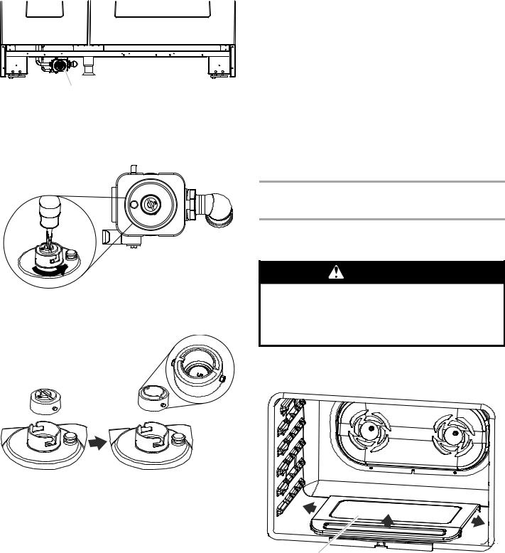
4. Locate the gas pressure regulator at the left rear of the range.
A
A.Gas pressure regulator
5.Remove the gas pressure regulator cap by using a large flatblade screwdriver, turning the regulator cap counterclockwise.
NOTE: Do not remove the spring beneath the cap.
6.Turn over the gas pressure regulator cap and reinstall on the regulator so that the hollow end faces out and the letters “LP” are visible.
7.Tighten the gas pressure regulator cap by using a large flatblade screwdriver, turning the regulator cap clockwise.
8.Test the gas pressure regulator and gas supply line.
The regulator must be checked at a minimum 1" (2.5 cm) water column above the set pressure. The inlet pressure to the regulator should be as follows for operation and checking the regulator setting:
LP Gas:
Minimum pressure 11" (27.9 cm) WCP
Maximum pressure 14" (35.6 cm) WCP.
Gas Supply Pressure Testing
Gas supply pressure for testing regulator must be at least 1" water column pressure above the manifold pressure shown on the model/serial rating plate.
Line pressure testing above ½ psi gauge (14" WCP)
The range and its individual shutoff valve must be disconnected from the gas supply piping system during any pressure testing of that system at test pressures in excess of ½ psi (3.5 kPa).
Line pressure testing at ½ psi gauge (14" WCP) or lower
The range must be isolated from the gas supply piping system by closing its individual manual shutoff valve during any pressure testing of the gas supply piping system at test pressures equal to or less than ½ psi (3.5 kPa).
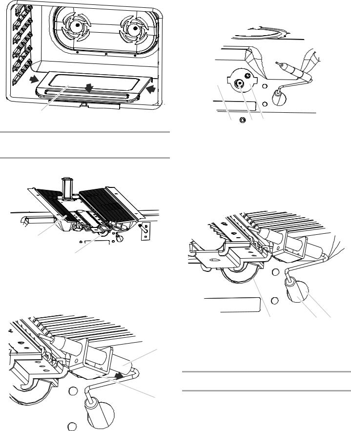
To Convert Oven Bake Burner (30" [76.2 cm] and 36" [91.4 cm] models and the Right Oven Cavity on 48" [121.9 cm] models)
1.Remove oven racks and the extendable roller rack from inside the oven cavity. See the “Extendable Roller Rack” section in the Use and Care Guide.
WARNING
Excessive Weight Hazard
Use two or more people to move and install oven doors.
Failure to do so can result in back or other injury.
2.Remove the oven door. See the “Oven Door” section in the Use and Care Guide.
3.Slide the bake burner cover to the right or left.
A
A. Bake burner cover
14

4.Lift up and remove oven bake burner cover and set aside.
5.Unscrew oven baffle nuts and remove oven baffle. Set aside.
AB
A.Oven baffle
B.Oven baffle nuts
6.Remove the oven bake burner screws and oven bake burner and gently set aside.
D C
A |
B |
A. Oven bake burner screws |
C. Oven bake burner electrode |
B. Oven bake burner |
bracket |
|
D. Oven bake burner electrode |
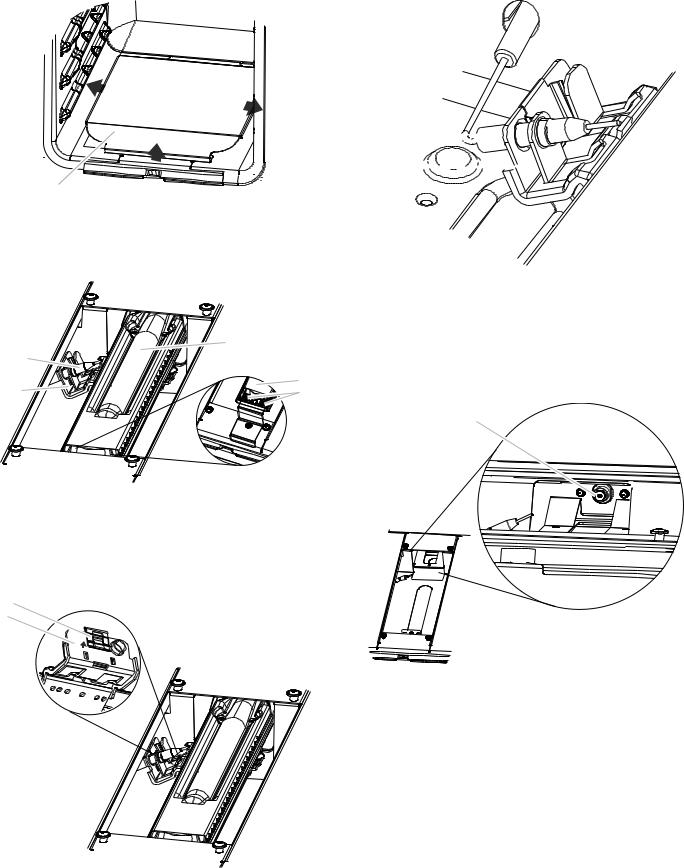
7.Lift up clip on the oven bake burner electrode bracket with a finger or flat-blade screwdriver.
B
A
A.Oven bake burner electrode bracket
B.Electrode bracket clip
8.Pull electrode out of bracket.
A
B 
A.Grasp electrode here.
B.Bracket
15

9.Apply masking tape to the end of a 7 mm nut driver to help hold the gas orifice spud in the nut driver while changing it. Insert nut driver into the gas opening and press down onto the gas orifice spud and remove by turning the gas orifice spud counterclockwise and lifting out. Set gas orifice spud aside.
13. Replace oven bake burner electrode inside bracket.
B
A A


A.Gas orifice spud
10.Gas orifice studs are stamped with a letter and a number. Install the Number 125 oven bake burner orifice spud.
11.Place Natural gas orifice in plastic parts bag for future use and keep with package containing literature.
12.Push down on the clip on the electrode bracket.
B
A
A.Oven bake burner electrode bracket
B.Electrode bracket clip
A.Oven bake burner electrode
B.Oven bake burner electrode bracket
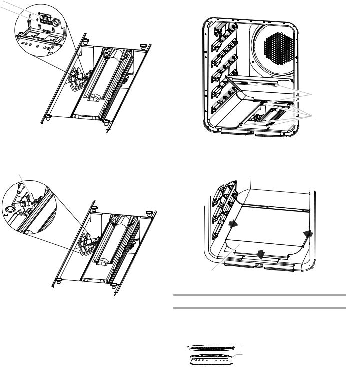
14.Reinstall the oven bake burner and oven bake burner screws. See Step 6 for illustration.
15.Replace oven baffle and oven baffle nuts.
Replace Oven Bake Burner Cover
1.Align notches on the oven bake burner cover with shoulder screws in the bottom of the oven.
A
A B B
A.Cover notches (4)
B.Shoulder screws (4)
16
2.Lower cover and slide to left or right to slide shoulder screws into the narrow ends of the notches and lock into place.
3.Apply masking tape to the end of a 7 mm nut driver to help hold the gas orifice spud in the nut driver while changing it. Insert nut driver into the gas opening and press down onto the gas orifice spud and remove by turning the gas orifice spud counterclockwise and lifting out. Set gas orifice spud aside.
A
A. Bake burner cover
To Convert Oven Broil Burner (30" [76.2 cm] and 36" [91.4 cm] models and the Right Oven Cavity on 48" [121.9 cm] models)
1. Remove broil burner screw and set aside.
A 
B
C
A.Broil burner screw
B.Broil burner
C.Broil burner orifice hole
2.Pull the broil burner toward you until it slides out of the hole in the oven back, and pull the electrode out of the bracket. The broil burner will hang down in the back of the oven while you change the orifice.
A
B
A.Grasp electrode here.
B.Bracket
AB C
A.Oven back
B.Broil burner orifice
C.Broil burner orifice hole
4.Gas orifice studs are stamped with a letter and a number. Install the Number 97 oven broil burner orifice spud.
5.Place Natural gas orifice in plastic parts bag for future use and keep with package containing literature.
6.Replace the broil burner in the hole in the oven back, with the broil burner electrode inside the broil burner electrode hole, as illustrated.
A B C
A.Broil burner orifice hole
B.Broil burner electrode
C.Broil burner electrode hole
7.Reinstall the oven broil burner screw. See Step 1 for illustration.
To Convert Oven Bake Burner (Left Oven Cavity on 48" [121.9 cm] models)
1.Remove oven racks.
2.Remove the oven door. See the “Oven Door” section in the Use and Care Guide.
17
3. Slide the bake burner cover to the right or left.
A
A.Bake burner cover
4.Lift up and remove oven bake burner cover and set aside.
5.Remove the oven bake burner screws and oven bake burner and gently set aside.
|
A |
D |
|
C |
A |
B |
A.Oven bake burner
B.Oven bake burner screws
C.Oven bake burner electrode bracket
D.Oven bake burner electrode
6.Lift up clip on the oven bake burner electrode bracket with a finger or flat-blade screwdriver
B
A
A.Oven bake burner electrode bracket
B.Electrode bracket clip
7. Pull electrode out of bracket.
A
B 
A.Grasp electrode here.
B.Bracket
8.Apply masking tape to the end of a 7 mm nut driver to help hold the gas orifice spud in the nut driver while changing it. Insert nut driver into the gas opening and press down onto the gas orifice spud and remove by turning the gas orifice spud counterclockwise and lifting out. Set gas orifice spud aside.
A
A.Gas orifice spud
9.Gas orifice studs are stamped with a letter and a number. Install the Number 105 oven bake burner orifice spud.
10.Place Natural gas orifice in plastic parts bag for future use and keep with package containing literature.
18
11. Push down on the clip on the electrode bracket.
B
A
A.Oven bake burner electrode bracket
B.Electrode bracket clip
12.Replace oven bake burner electrode inside bracket.
B
A


A.Oven bake burner electrode
B.Oven bake burner electrode bracket
13.Reinstall the oven bake burner and oven bake burner screws. See Step 5 for illustration.
Replace Oven Bake Burner Cover
1.Align rear shoulder screw mounting holes (keyholes) on the oven bake burner cover with shoulder screws in the bottom of the oven.
 A
A
B
A.Shoulder screw mounting holes (keyholes)
B.Shoulder screws
2.Drop cover and slide to left or right to slide shoulder screws into narrow ends of keyholes and lock into place.
A
A. Bake burner cover
To Convert Surface Burners
1.If the burner grates are installed, remove them.
2.Remove burner cap.
3.Remove the burner base.
|
A |
Large Dual Burner |
|
A. Burner cap |
|
|
B |
|
|
B. Burner base |
|
|
A |
Medium Burner |
|
A. Burner cap |
|
C |
B |
B. Burner base |
|
|
C. Choke (for use with medium |
|
|
burner, LP gas only) |
|
A |
Small Burner |
|
|
BA. Burner cap B. Burner base
19
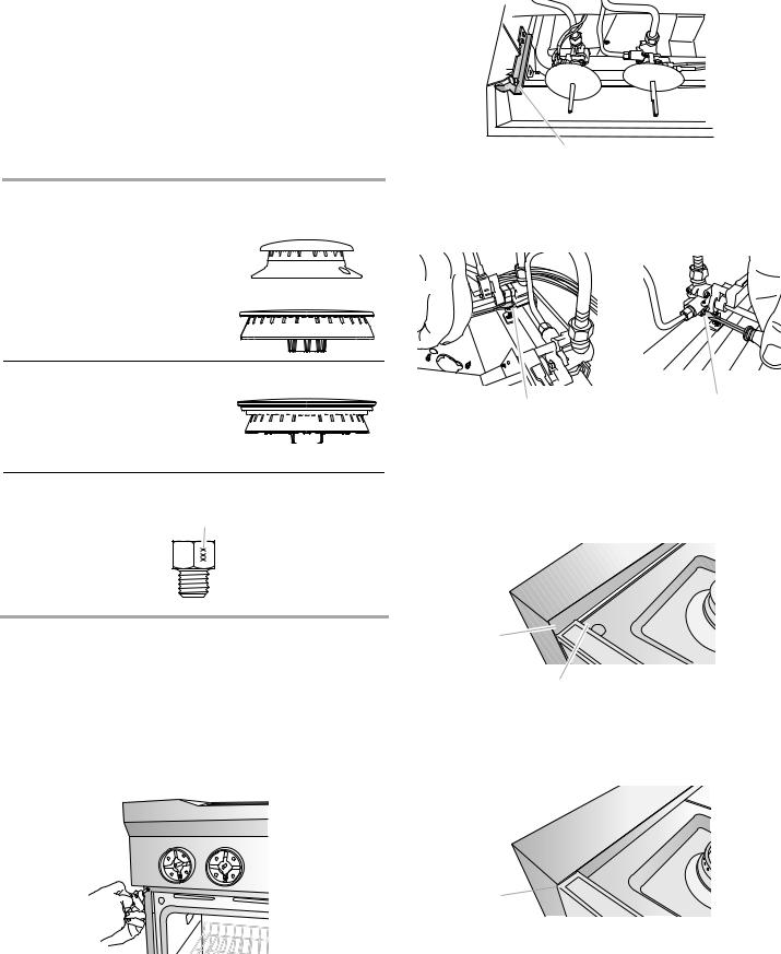
4.Apply masking tape to the end of a 7 mm nut driver to help hold the gas orifice spud in the nut driver while changing it. Insert nut driver into the gas opening and press down onto the gas orifice spud and remove by turning the gas orifice spud counterclockwise and lifting out. Set gas orifice spud aside.
5.Replace with correct LP gas orifice spud. See the “LP Gas Orifice Spud/Hood Chart.”
Use the following chart to find the exact orifice spud placement.
Fully insert choke into bottom of medium burner base. Choke should snap into place.
LP Gas Orifice Spud/Hood Chart
Burner |
Color |
Size |
Burner Style |
||||||
Rating |
|
|
|
|
|
|
|
|
|
|
|
|
|
|
|
|
|
|
|
3,000 BTU |
Blue |
0.55 mm |
Small burners |
||||||
|
|
|
|
|
|
|
|
|
|
|
|
|
|
|
|
|
|
|
|
|
|
|
|
|
|
|
|
|
|
|
|
|
|
|
|
|
|
|
|
|
|
|
|
|
|
|
|
|
|
11,000 BTU Yellow 0.97 mm Medium burners
14,000 BTU Red/ |
1.05 mm |
Large burner - main |
||||||||||||
Green |
0.35 mm |
Large burner - simmer |
||||||||||||
|
|
|
|
|
|
|
|
|
|
|
|
|
|
|
|
|
|
|
|
|
|
|
|
|
|
|
|
|
|
|
|
|
|
|
|
|
|
|
|
|
|
|
|
|
|
|
|
|
|
|
|
|
|
|
|
|
|
|
|
14,500 BTU Black 1.18 mm Grill burner
Burner orifice spud
A
A.Size stamp or color
6.Place Natural gas orifice in plastic parts bag for future use and keep with package containing literature.
7.Replace the burner base.
8.Replace burner cap.
9.Repeat steps 2 through 8 for the remaining burners.
10.Unplug range or disconnect power.
11.Remove the control knobs.
12.Open the oven door and remove the 2 screws on each side of the range that hold the control console in place.
NOTE: Make sure to leave oven door open or the control console will not rest in the side brackets properly once it is detached.
13.Pull up on the control console and let it drop forward into the notched console brackets on each side.
A
A.Control console bracket
14.Remove the round gasket from the valve stem.
15.Use a ¹⁄ " x 4¼" flat-blade screwdriver to completely screw down all burner screws.
A B
A.Single flame burner adjustment screw (on right side of valve)
B.Dual flame burner adjustment screw (on left side of valve)
16.Replace the round gasket.
17.Lift up on the control console and set it back into place. For a proper fit, the flange of the control console must hook over the lip on the front of the range cooktop.
A
B
A.Control console flange
B.Front lip of range cooktop
18.Check that the control console is flush with the top edge of the range.
A 

A.Flush with range top
19.Replace the 2 screws on each side of the control console.
20.Replace the control knobs.
21.Replace burner grates.
20
Complete Installation
1.Refer to the “Make Gas Connection” section for properly connecting the range to the gas supply.
2.Refer to the “Electronic Ignition System” section for proper burner ignition, operation, and burner flame adjustments.
IMPORTANT: You may have to adjust the “LO” setting for each cooktop burner.
Checking for proper cooktop burner flame is very important. The small inner cone should have a very distinct blue flame ¼" (0.64 cm) to ½" (1.3 cm) long. The outer cone is not as distinct as the inner cone. LP gas flames have a slightly yellow tip.
3.Refer to “Complete Installation” in the “Installation Instructions” section of this manual to complete this procedure.
Natural Gas Conversion
WARNING
Tip Over Hazard
A child or adult can tip the range and be killed.
Install anti-tip bracket to floor or wall per installation instructions.
Slide range back so rear range foot is engaged in the slot of the anti-tip bracket.
Re-engage anti-tip bracket if range is moved.
Do not operate range without anti-tip bracket installed and engaged.
Failure to follow these instructions can result in death or serious burns to children and adults.
1. Turn the manual shutoff valve to the closed position.
 B
B
A
C
A.To range
B.Shutoff valve (closed position)
C.Gas supply line
2.Unplug range or disconnect power.
To Convert Gas Pressure Regulator
1. Remove screws from kick plate.
B
A
A.Kick plate
B.Remove these screws.
2.Push up on kick plate to release plate from shoulder screws.
3.Gently lay kick plate aside to avoid scratching the stainless steel.
4.Locate the gas pressure regulator at the left rear of the range.
A
A.Gas pressure regulator
5.Remove the gas pressure regulator cap by using a large flatblade screwdriver, turning the regulator cap counterclockwise.
NOTE: Do not remove the spring beneath the cap.
21
 Loading...