


 Loading...
INSTALLATION INSTRUCTIONS
24", 30", AND 36" (61.0 CM, 76.2 CM, AND 91.4 CM) TOUCH-ACTIVATED ELECTRONIC INDUCTION COOKTOP
INSTRUCTIONS D’INSTALLATION
TABLE DE CUISSON À INDUCTION AVEC COMMANDES ÉLECTRONIQUES TACTILES DE 24 PO, 30 PO ET 36 PO (61,0 CM, 76,2 CM ET 91,4 CM)
Table of Contents/Table des matières
COOKTOP SAFETY........................................................................ |
1 |
INSTALLATION REQUIREMENTS................................................. |
3 |
Tools and Parts............................................................................. |
3 |
Location Requirements................................................................. |
3 |
Electrical Requirements................................................................ |
5 |
INSTALLATION INSTRUCTIONS................................................... |
6 |
Prepare Cooktop for Installation................................................... |
6 |
Install Cooktop.............................................................................. |
6 |
Make Electrical Connection.......................................................... |
7 |
Complete Installation.................................................................... |
8 |
SÉCURITÉ DE LA TABLE DE CUISSON....................................... |
9 |
EXIGENCES D’INSTALLATION.................................................... |
11 |
Outils et pièces........................................................................... |
11 |
Exigences d’emplacement......................................................... |
11 |
Spécifications électriques........................................................... |
13 |
INSTRUCTIONS D’INSTALLATION............................................. |
14 |
Préparation de la table de cuisson pour l’installation................ |
14 |
Installation de la table de cuisson.............................................. |
14 |
Raccordement électrique........................................................... |
15 |
Terminer l’installation.................................................................. |
16 |
COOKTOP SAFETY
IMPORTANT: |
Save for local electrical inspector’s use.
IMPORTANT :
Conserver ces instructions à l’usage de l’inspecteur des installations électriques local.
W11251690A

IMPORTANT SAFETY INSTRUCTIONS |
READ AND SAVE THESE INSTRUCTIONS |
2
INSTALLATION REQUIREMENTS
Tools and Parts
Gather the required tools and parts before starting installation. Read and follow the instructions provided with any tools listed here.
Tools Needed
■■ Tape measure
■■ Phillips screwdriver ■■ Flat-blade screwdriver ■■ Marker or pencil
■■ Pliers
Parts Supplied
Check that all parts are included. ■■ Cooktop assembly
■■ (2) Hold-down brackets
■■ (2) 1" (2.5 cm) clamping screws ■■ Foam tape seal
■■ Foam strip
Parts Needed
■■ (4) UL listed 22-6 AWG Twist on Connectors
Check local codes. Check existing electrical supply. See the “Electrical Requirements” section.
It is recommended that all electrical connections be made by a licensed, qualified electrical installer.
Location Requirements
IMPORTANT: Observe all governing codes and ordinances. When installing cooktop, use minimum dimensions given.
■■ The cooktop must be a specified cooktop that is approved to be installed either alone or over an undercounter built-in oven. Check the cooktop base for an approved installation label. If you do not find this label, contact your dealer to confirm that your cooktop is approved.
■■ To eliminate the risk of burns or fire by reaching over heated surface units, cabinet storage space located above the surface units should be avoided. If cabinet storage is to be provided, the risk can be reduced by installing a range hood that projects horizontally a minimum of 5” (12.7 cm) beyond the bottom of the cabinets.
■■ The cooktop must be installed in a level countertop.
■■ Ovens approved for this type of installation will have an approval label located on the top of the oven. If you do not find this label, contact your dealer to confirm that your oven is approved. Refer to oven manufacturer’s Installation Instructions for approval for built-in undercounter use and proper cutout dimensions.
■■ The cooktop should be installed away from strong draft areas, such as windows, doors, fans, or strong heating vents. The cooktop should be located for convenient use in the kitchen.
■■ Use the countertop opening dimensions that are given with these Installation Instructions. Given dimensions are minimum clearances and provide 0" (0 cm) clearance.
■■ Grounded electrical supply is required. See the “Electrical Requirements” section.
IMPORTANT: To avoid damage to your cabinets, check with your builder or cabinet supplier to make sure that the materials used will not discolor, delaminate, or sustain other damage. This cooktop has been designed in accordance with the requirements of UL and CSA International and complies with the maximum allowable wood cabinet temperatures of 194°F (90°C).
The model/serial/rating label is located on the bottom of the electrical junction box cover.
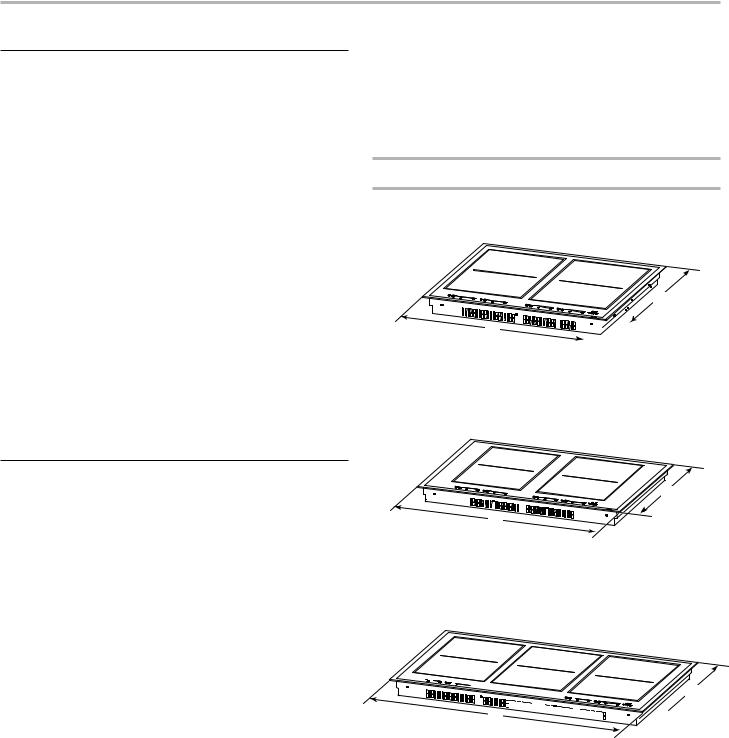
Product Dimensions
24" (61.0 cm) Cooktop
(Model JIC4724HB, JIC4724HS)
Top View
A
B
A.21" (53.3 cm)
B.24" (61.0 cm)
30" (76.2 cm) Cooktop
(Model JIC4730HB, JIC4730HS)
Top View
 A
A
B
A. 21" (53.3 cm)
B. 30" (76.2 cm)
36" (91.4 cm) Cooktop
(Model JIC4736HS, JIC4736HB)
Top View

 A B
A B 


A.21" (53.3 cm)
B.36" (91.4 cm)
3
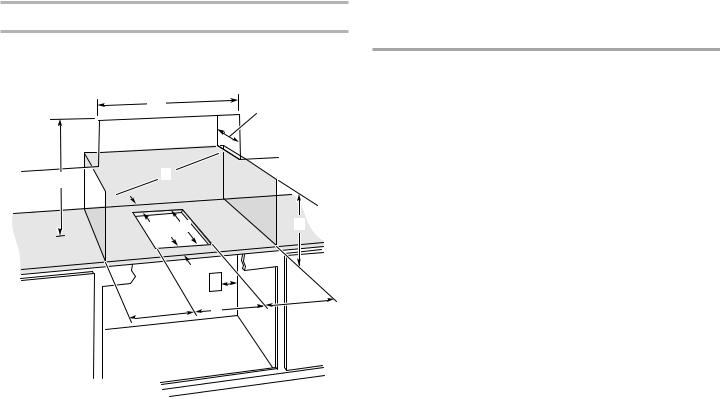
Cabinet Dimensions
IMPORTANT: If installing a range hood or microwave hood combination above the cooktop, follow the range hood or microwave hood combination installation instructions for dimensional clearances above the cooktop surface.
A
D
C 
 B
B 
L E F |
G |
H
I
K J
A.Minimum upper cabinet width. See the “Standard Install Dimensions” table.
B.Combustible area above countertop (shown by dashed box above)
C.30" (76.2 cm) minimum clearance between top of cooktop platform and bottom of uncovered wood or metal cabinet (24" [61.0 cm] minimum clearance if bottom of wood or metal cabinet is covered by not less than 1/4" [0.06 mm] flame retardant millboard covered with not less than No. 28 MSG sheet steel, 0.015" [0.04 cm] stainless steel, or 0.024" [0.06 cm] aluminum or 0.020" [0.05 cm] copper)
D.13" (33 cm) recommended upper cabinet depth
E.25/6" (5.9 cm) minimum distance to front countertop edge
F.203/8" (51.8 cm)
G.18" (45.7 cm) minimum clearance from upper cabinet to countertop within minimum horizontal clearances to cooktop
H.Junction box or outlet: 7" (17.8 cm) minimum from top of countertop
I.Junction box or outlet: 9" (23.0 cm) maximum from right side of cabinet
J.See the “Standard Install Dimensions” Table
K.6" (15.2 cm) minimum side wall clearance
L.25/16" (5.9 cm) minimum distance to rear combustible surface
Standard Install Dimensions Table
NOTE: When pairing cooktops, this option is recommended only with stainless steel or framed cooktops.
Units |
Upper Cabinet |
Cutout |
|
Width (A) |
Width (J) |
||
|
|||
|
|
|
|
One 15" (38.1 cm) unit |
15" |
143/8" |
|
|
(38.1 cm) |
(36.5 cm) |
|
Two 15" (38.1 cm) units |
30" |
293/8" |
|
|
(76.2 cm) |
(74.6 cm) |
|
|
|
|
|
Three 15" (38.1 cm) units |
45" |
447/16" |
|
|
(114.3 cm) |
(112.9 cm) |
|
Four 15" (38.1 cm) units |
60" |
597/16" |
|
|
(152.4 cm) |
(151.0 cm) |
|
|
|
|
|
24" (61.0 cm) cooktop |
24" |
2231/32" |
|
|
(61.0 cm) |
(58.3 cm) |
|
|
|
|
|
24" (61.0 cm) cooktop and |
39" |
383/16" |
|
one 15" (38.1 cm) unit |
(99.1 cm) |
(97.0 cm) |
|
24" (61.0 cm) cooktop and |
54" |
533/8" |
|
two 15" (38.1 cm) units |
(137.2 cm) |
(135.6 cm) |
|
|
|
|
|
30" (76.2 cm) cooktop |
30" |
2831/32" |
|
|
(76.2 cm) |
(73.6 cm) |
|
30" (76.2 cm) cooktop and |
45" |
443/16" |
|
one 15" (38.1 cm) unit |
(114.3 cm) |
(112.2 cm) |
|
|
|
|
|
30" (76.2 cm) cooktop and |
60" |
593/16" |
|
two 15" (38.1 cm) units |
(152.4 cm) |
(150.3 cm) |
|
36" (91.4 cm) cooktop |
36" |
3431/32" |
|
|
(91.4 cm) |
(88.8 cm) |
|
|
|
|
|
36" (91.4 cm) cooktop and |
51" |
503/16" |
|
one 15" (38.1 cm) unit |
(129.5 cm) |
(127.5 cm) |
NOTE: After making the countertop cutout, some installations may require notching down the base cabinet side walls to clear the cooktop base. To avoid this modification, use a base cabinet with sidewalls wider than the cutout.
If cabinet has a drawer, a 51/2" (14.0 cm) depth clearance from the countertop to the top of the drawer (or other obstruction) in base cabinet is required.
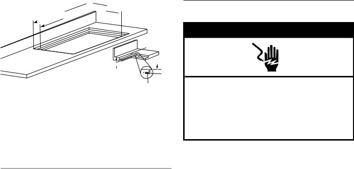
Flush Installation Dimensions
All cooktops can be mounted with a frameless standard installation sitting on top of the countertop surface or flush with the top of the countertop.
If the cooktop is to be mounted flush with the countertop, a recessed area surrounding the cooktop cutout must be provided with the following dimensions:
1.11/64" (4.3 mm) recessed depth is needed for the SS Frame Model (see dimension E).
2.7/32" (5.6 mm) recessed depth is needed for the Glass Model without a frame.
NOTE: This option is not recommended for countertops with a molded backsplash. Do not silicone seal in place.
4
 DC
DC
 B A
B A

F
E
Cooktop


E
Foam Strip (optional)
A.Recessed area length 213/16" (53.8 cm)
B.Cutout length 203/8" (51.8 cm)
C.See the “Flush Install Dimension” table.
D.See the “Flush Install Dimension” table.
E.Recessed area depth 11/64" (4.3 mm)
F.Recessed area radius 5/64" (2.0 mm) maximum
Flush Install Dimension Table
Units |
Recessed Area |
Cutout |
|
Width (D) |
Width (C) |
||
|
|||
|
|
|
|
One 15" (38.1 cm) unit |
151/8" |
143/8" |
|
|
(38.4 cm) |
(36.5 cm) |
|
|
|
|
|
Two 15" (38.1 cm) units |
301/8" |
293/8" |
|
|
(76.5 cm) |
(74.6 cm) |
|
Three 15" (38.1 cm) units |
451/8" |
447/16" |
|
|
(114.6 cm) |
(112.9 cm) |
|
|
|
|
|
Four 15" (38.1 cm) units |
601/8" |
597/16" |
|
|
(152.7 cm) |
(151.0 cm) |
|
24" (61.0 cm) cooktop |
241/8" (61.3 cm) |
233/8" |
|
|
|
(59.4 cm) |
|
|
|
|
|
24" (61.0 cm) and |
391/8" |
383/16" |
|
one 15" (38.1 cm) cooktop |
(99.4 cm) |
(97.0 cm) |
|
24" (61.0 cm) and |
54 1/8" |
533/8" |
|
two 15" (38.1 cm) cooktop |
(137.5 cm) |
(135.6 cm) |
|
|
|
|
|
30" (76.2 cm) cooktop |
301/8" (76.5 cm) |
293/8" |
|
|
|
(74.6 cm) |
|
|
|
|
|
30" (76.2 cm) cooktop and |
451/8" |
443/16" |
|
one 15" (38.1 cm) unit |
(114.6 cm) |
(112.2 cm) |
|
30" (76.2 cm) cooktop and |
601/8" |
593/8" |
|
two 15" (38.1 cm) units |
(152.7 cm) |
(150.8 cm) |
|
|
|
|
|
36" (91.4 cm) cooktop |
361/8" |
353/8" |
|
|
(91.8 cm) |
(89.9 cm) |
|
36" (91.4 cm) cooktop and |
511/8" |
503/16" |
|
one 15" (38.1 cm) unit |
(129.9 cm) |
(127.5 cm) |
IMPORTANT: If multiple units are installed side by side, the mounting bridge kit W11031680 is needed for proper installation.
Electrical Requirements
 WARNING
Electrical Shock Hazard Disconnect power before servicing. Use 8 gauge copper wire.
Electrically ground cooktop.
Failure to follow these instructions can result in death, fire, or electrical shock.
If codes permit and a separate ground wire is used, it is recommended that a qualified electrical installer determine that the ground path and wire gauge are in accordance with local codes.
Check with a qualified electrical installer if you are not sure the cooktop is properly grounded.
Make sure that the electrical connection and wire size are adequate and in conformance with the National Electrical Code, ANSI/NFPA 70—latest edition or CSA Standards C22.1—94, Canadian Electrical Code, Part 1 and C22.2 No. O-M91-latest edition, and all local codes and ordinances.
A copy of the above code standards can be obtained from:
National Fire Protection Association
1 Batterymarch Park
Quincy, MA 02169-7471
CSA International
8501 East Pleasant Valley Road
Cleveland, OH 44131-5575
5
Loading...