


JGC9430ADB
Jenn-Air JGC9430ADB, JGC9430ADF, JGC9430ADS, JGC9430BDB, JGC9430BDF Installation Guide
...
SEALEDGASCOOKTOPS
Models: JGC9430 & JGC9536
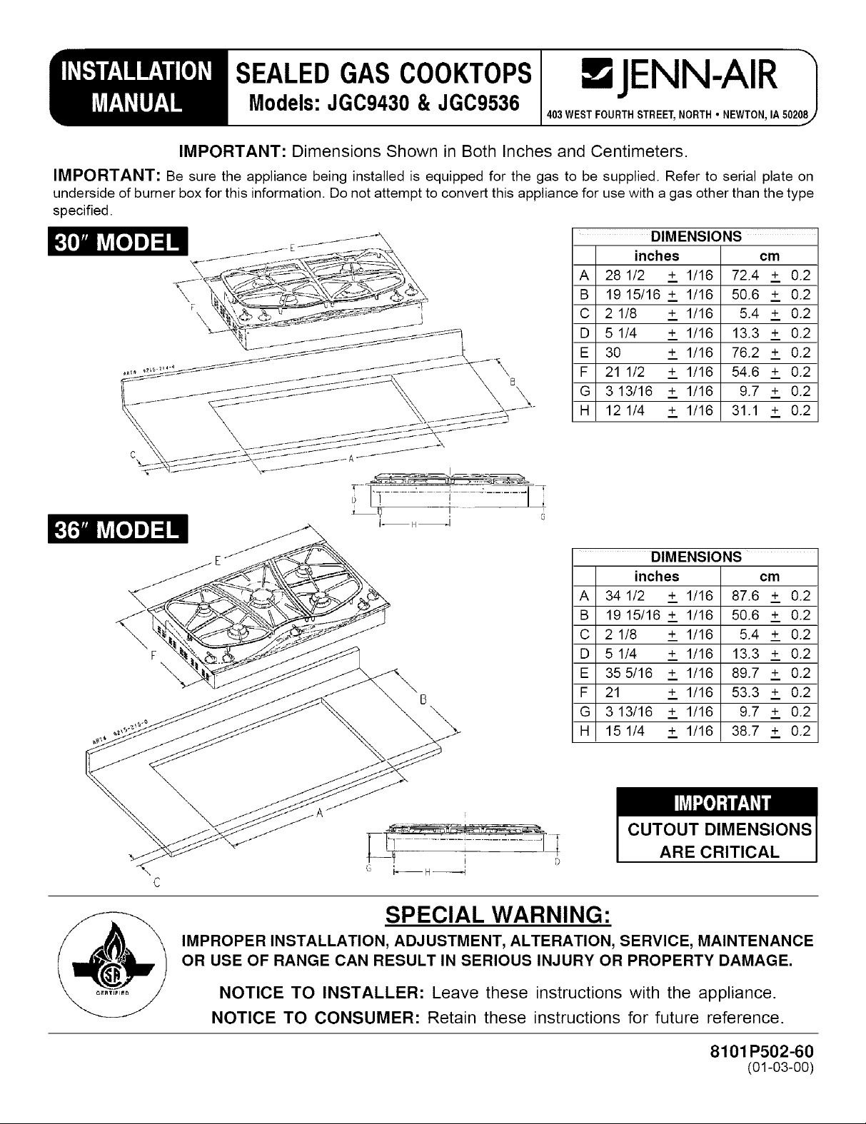
IMPORTANT: Dimensions Shown in Both Inches and Centimeters.
IMPORTANT: Be sure the appliance being installed is equipped for the gas to be supplied. Refer to serial plate on
underside of burner box for this information. Do not attempt to convert this appliance for use with a gas other than the type
specified.
.JENN-AIR
403WESTFOURTHSTREET,NORTH NEWTON,IA50201
DIMENSIONS
inches cm
A 28 1/2 + 1/16 72.4 + 0.2
B 19 15/16 + 1/16 50.6 + 0.2
C 21/8 + 1/16 5.4 + 0.2
D 51/4 + 1/16 13.3 + 0.2
E 30 + 1/16 76.2 + 0.2
F 21 1/2 + 1/16 54.6 + 0.2
G 313/16 + 1/16 9.7 + 0.2
H 12 1/4 + 1/16 31.1 + 0.2
DIMENSIONS
inches cm
A 34 1/2 + 1/16 87.6 + 0.2
B 19 15/16 + 1/16 50.6 + 0.2
C 21/8 + 1/16 5.4 + 0.2
D 5 1/4 + 1/16 13.3 + 0.2
E 355/16 + 1/16 89.7 + 0.2
F 21 + 1/16 53.3 + 0.2
G 313/16 + 1/16 9.7 + 0.2
H 151/4 + 1/16 38.7 + 0.2
\
\
\
CUTOUT DIMENSIONS
ARE CRITICAL
SPECIAL WARNING:
IMPROPER INSTALLATION, ADJUSTMENT, ALTERATION, SERVICE, MAINTENANCE
OR USE OF RANGE CAN RESULT IN SERIOUS INJURY OR PROPERTY DAMAGE.
NOTICE TO INSTALLER: Leave these instructions with the appliance.
NOTICE TO CONSUMER: Retain these instructions for future reference.
8101 P502-60
(01-03-00)
Location Of Your Jenn-Air
Important Preparation
Appliance
Locate this appliance away from combustible materials
such as window curtains and combustible wall
decorations.
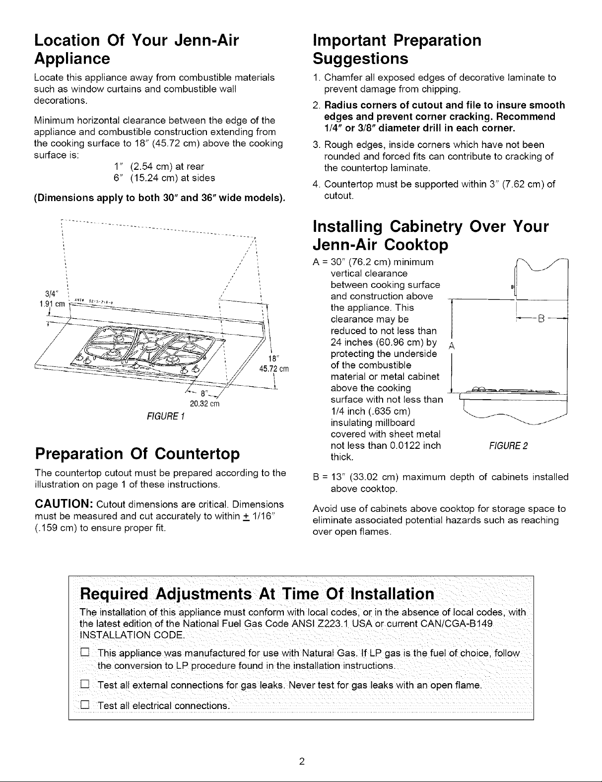
Minimum horizontal clearance between the edge of the
appliance and combustible construction extending from
the cooking surface to 18" (45.72 cm) above the cooking
surface is:
1" (2.54 cm) at rear
6" (15.24 cm) at sides
(Dimensions apply to both 30" and 36" wide models).
/ i
/ i
/
3/4"
1.91cm
20.32 cm
RGURE1
Preparation Of Countertop
The countertop cutout must be prepared according to the
illustration on page 1 of these instructions.
CAUTION: Cutout dimensions are critical. Dimensions
must be measured and cut accurately to within + 1/16"
(.159 cm) to ensure proper fit.
Suggestions
1. Chamfer all exposed edges of decorative laminate to
prevent damage from chipping.
2. Radius corners of cutout and file to insure smooth
edges and prevent corner cracking. Recommend
1/4" or 3/8" diameter drill in each corner.
3. Rough edges, inside corners which have not been
rounded and forced fits can contribute to cracking of
the countertop laminate.
4. Countertop must be supported within 3" (7.62 cm) of
cutout.
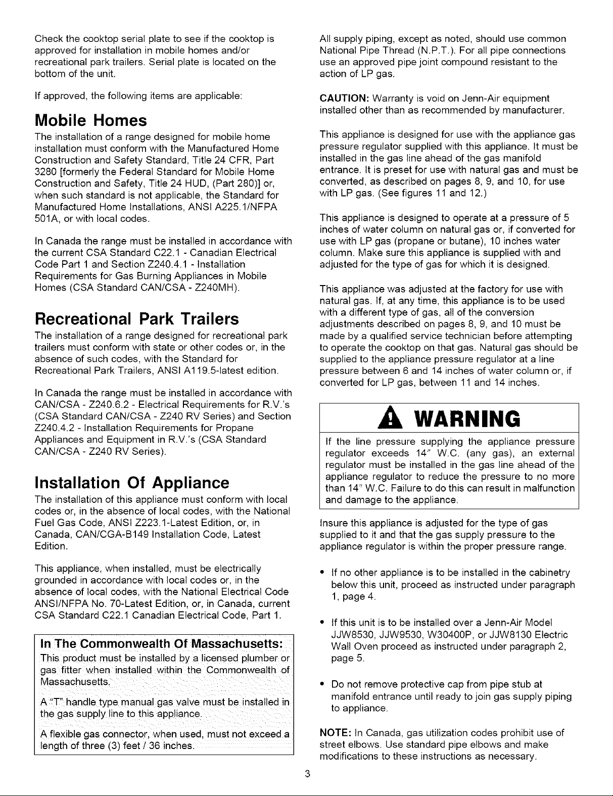
Installing
Cabinetry Over Your
Jenn-Air Cooktop
A = 30" (76.2 cm) minimum
vertical clearance
between cooking surface
and construction above
the appliance. This
clearance may be
reduced to not less than
24 inches (60.96 cm) by
protecting the underside
of the combustible
material or metal cabinet
above the cooking
surface with not less than
1/4 inch (.635 cm)
insulating millboard
covered with sheet metal
not less than 0.0122 inch
thick.
B = 13" (33.02 cm) maximum depth of cabinets installed
above cooktop.
Avoid use of cabinets above cooktop for storage space to
eliminate associated potential hazards such as reaching
over open flames.
A
t
FIGURE2
Required Adjustments At Time Of Installation
The installation of this appliance must conform with local codes, or in the absence of local codes, with
the latest edition of the National Fuel Gas Code ANSI Z223.1 USA or current CAN/CGA-B149
INSTALLATION CODE.
[] This appliance was manufactured for use with Natural Gas. If LP gas is the fuel of choice, follow
the conversion to LP procedure found in the installation instructions.
[] Test all external connections for gas leaks. Never test for gas leaks with an open flame.
[] Test all electrical connections.
Checkthecooktopserialplatetoseeifthecooktopis
approvedforinstallationinmobilehomesand/or
recreationalparktrailers.Serialplateislocatedonthe
bottomoftheunit.
All supply piping, except as noted, should use common
National Pipe Thread (N.P.T.). For all pipe connections
use an approved pipe joint compound resistant to the
action of LP gas.
Ifapproved,thefollowingitemsareapplicable:
Mobile Homes
The installation of a range designed for mobile home
installation must conform with the Manufactured Home
Construction and Safety Standard, Title 24 CFR, Part
3280 [formerly the Federal Standard for Mobile Home
Construction and Safety, Title 24 HUD, (Part 280)] or,
when such standard is not applicable, the Standard for
Manufactured Home Installations, ANSI A225.1/NFPA
501A, or with local codes.
In Canada the range must be installed in accordance with
the current CSA Standard C22.1 - Canadian Electrical
Code Part 1 and Section Z240.4.1 - Installation
Requirements for Gas Burning Appliances in Mobile
Homes (CSA Standard CAN/CSA - Z240MH).
Recreational Park Trailers
The installation of a range designed for recreational park
trailers must conform with state or other codes or, in the
absence of such codes, with the Standard for
Recreational Park Trailers, ANSI A119.5-latest edition.
In Canada the range must be installed in accordance with
CAN/CSA - Z240.6.2 - Electrical Requirements for R.V.'s
(CSA Standard CAN/CSA - Z240 RV Series) and Section
Z240.4.2 - Installation Requirements for Propane
Appliances and Equipment in R.V.'s (CSA Standard
CAN/CSA - Z240 RV Series).
Installation Of Appliance
The installation of this appliance must conform with local
codes or, in the absence of local codes, with the National
Fuel Gas Code, ANSI Z223.1-Latest Edition, or, in
Canada, CAN/CGA-B149 Installation Code, Latest
Edition.
CAUTION: Warranty is void on Jenn-Air equipment
installed other than as recommended by manufacturer.
This appliance is designed for use with the appliance gas
pressure regulator supplied with this appliance. It must be
installed in the gas line ahead of the gas manifold
entrance. It is preset for use with natural gas and must be
converted, as described on pages 8, 9, and 10, for use
with LP gas. (See figures 11 and 12.)
This appliance is designed to operate at a pressure of 5
inches of water column on natural gas or, if converted for
use with LP gas (propane or butane), 10 inches water
column. Make sure this appliance is supplied with and
adjusted for the type of gas for which it is designed.
This appliance was adjusted at the factory for use with
natural gas. If, at any time, this appliance is to be used
with a different type of gas, all of the conversion
adjustments described on pages 8, 9, and 10 must be
made by a qualified service technician before attempting
to operate the cooktop on that gas. Natural gas should be
supplied to the appliance pressure regulator at a line
pressure between 6 and 14 inches of water column or, if
converted for LP gas, between 11 and 14 inches.
A, WARNING
If the line pressure supplying the appliance pressure
regulator exceeds 14" W.C. (any gas), an external
regulator must be installed in the gas line ahead of the
appliance regulator to reduce the pressure to no more
than 14" W.C. Failure to do this can result in malfunction
and damage to the appliance.
Insure this appliance is adjusted for the type of gas
supplied to it and that the gas supply pressure to the
appliance regulator is within the proper pressure range.
This appliance, when installed, must be electrically
grounded in accordance with local codes or, in the
absence of local codes, with the National Electrical Code
ANSI/NFPA No. 70-Latest Edition, or, in Canada, current
CSA Standard C22.1 Canadian Electrical Code, Part 1.
In The Commonwealth Of Massachusetts:
This product must be installed by a licensed plumber or
gas fitter when installed within the Commonwealth of
Massachusetts.
A "T" handle type manual gas valve must be installed in
the gas supply ine to this appliance.
A flexible gas connector, when used. must not exceed a
length of three (3) feet / 36 inches.
- If no other appliance is to be installed in the cabinetry
below this unit, proceed as instructed under paragraph
1, page 4.
If this unit is to be installed over a Jenn-Air Model
JJW8530, JJW9530, W30400P, or JJW8130 Electric
Wall Oven proceed as instructed under paragraph 2,
page 5.
- Do not remove protective cap from pipe stub at
manifold entrance until ready to join gas supply piping
to appliance.
NOTE: In Canada, gas utilization codes prohibit use of
street elbows. Use standard pipe elbows and make
modifications to these instructions as necessary.
Connecting Appliance To Gas Supply
A QUALIFIED SERVICEMAN OR GAS APPLIANCE
INSTALLER MUST MAKE THE GAS SUPPLY
CONNECTION. Leak testing of the appliance shall
be conducted by the installer according to the
instructions given.
Gas supply piping MUST conform to all local,
municipal and state building codes and local utility
regulations.
1. IF NO OTHER APPLIANCE IS TO BE INSTALLED
BELOW THIS COOKTOP
Join the appliance pressure regulator supplied with this
appliance to the entrance threads of the Gas Manifold.
The appliance regulator is marked with a directional
arrow indicating correct direction of gas flow. Ensure
the appliance regulator is installed with the arrow
pointing toward the gas manifold entrance. Tighten the
appliance regulator to 20 to 30 ft-lbs of torque.
Never tighten to more than 35 ft-lbs of torque. Always
use an approved pipe joint compound resistant to the
action of LP gas.
Install the appliance in its counter cutout.
Make the gas connection to the inlet of the appliance
pressure regulator with 1/2" NPT male pipe threads.
Install a manual shut-off valve in an accessible location in
the gas line ahead of the appliance pressure regulator
and external to this appliance for the purpose of turning
on or shutting off gas to the appliance.
Make additional pipe connections as necessary ahead of
the shut-off valve to the gas supply source. Assure all
pipe joint connections are gas tight.
Apply a non-corrosive leak detection fluid to all joints and
fittings in the gas connection between the supply line
shut-off valve and the cooktop. Include gas fittings and
joints in the cooktop if connections were disturbed
during installation. Check for leaks! Bubbles appearing
around fittings and connections will indicate a leak. If a
leak appears, turn off supply line gas shut-off valve,
tighten connections, turn on the supply line gas shut off
valve, and retest for leaks. Never test for gas leaks with
an open flame.
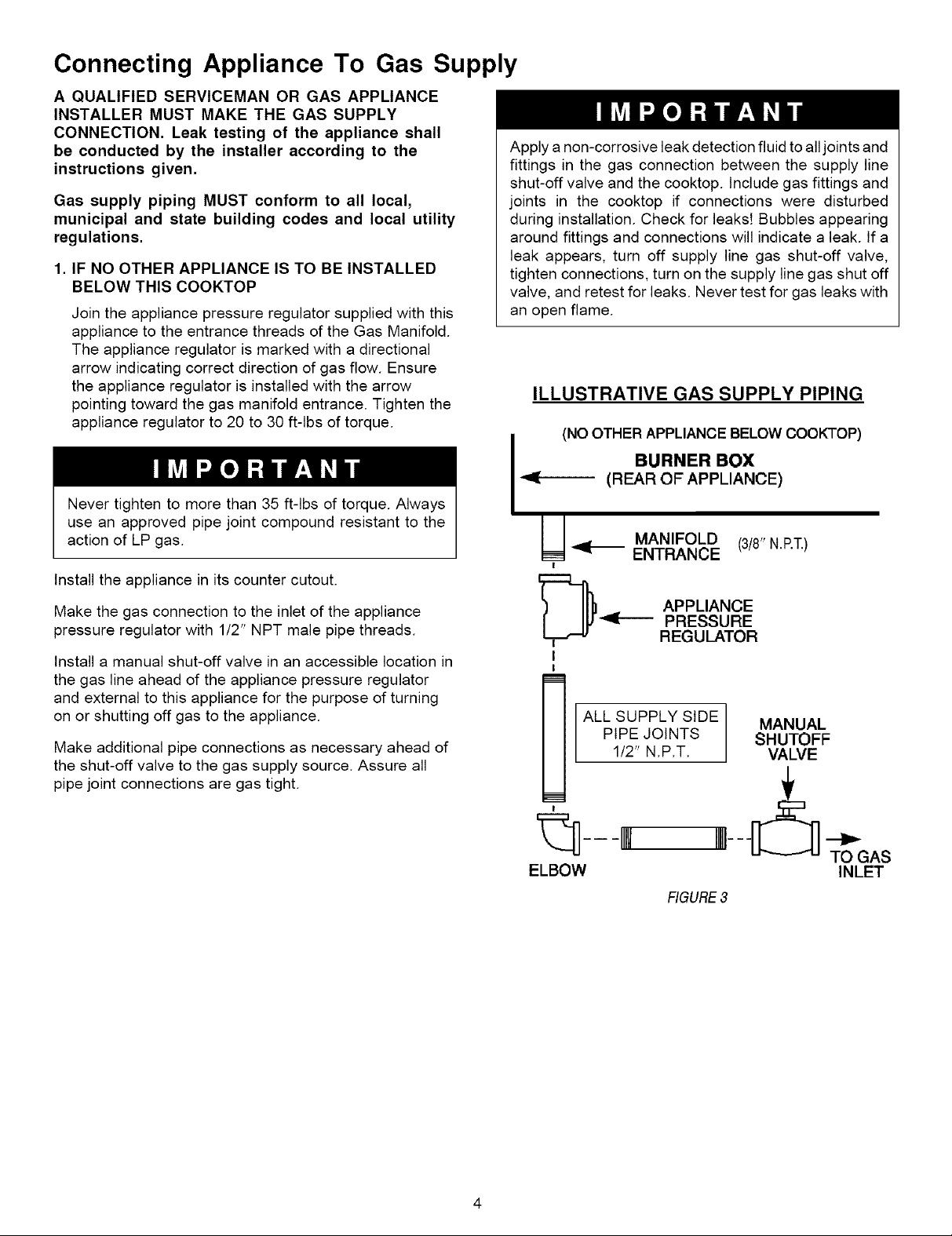
ILLUSTRATIVE GAS SUPPLY PIPING
(NOOTHER APPLIANCE BELOW COOKTOP)
BURNER BOX
(REAR OF APPLIANCE)
U MANIFOLD
I
D---
!
I
!
ALl_ SUPPLY SIDE
!
ENTRANCE
APPLIANCE
PRESSURE
REGULATOR
PIPE JOINTS
1/2" N.P.T.
(3/8"N.RT.)
MANUAL
SHUTOFF
VALVE
ELBOW
TO GAS
INLET
RGURE3
 Loading...