


 Loading...
LASERJET PRO 400
Troubleshooting Manual
 M401
M401

HP LaserJet Pro 400 M401 Printer Series
Troubleshooting Manual
Copyright and License
© 2012 Copyright Hewlett-Packard
Development Company, L.P.
Reproduction, adaptation, or translation without prior written permission is prohibited, except as allowed under the copyright laws.
The information contained herein is subject to change without notice.
The only warranties for HP products and services are set forth in the express warranty statements accompanying such products and services. Nothing herein should be construed as constituting an additional warranty. HP shall not be liable for technical or editorial errors or omissions contained herein.
Part number: CF270-91001
Edition 1, 4/2012
Trademark Credits
Microsoft®, Windows®, Windows® XP, and Windows Vista® are U.S. registered trademarks of Microsoft Corporation.

Conventions used in this guide

 TIP: Tips provide helpful hints or shortcuts.
 NOTE: Notes provide important information to explain a concept or to complete a task.
CAUTION: Cautions indicate procedures that you should follow to avoid losing data or damaging the product.
WARNING! Warnings alert you to specific procedures that you should follow to avoid personal injury, catastrophic loss of data, or extensive damage to the product.
ENWW |
iii |
iv |
Conventions used in this guide |
ENWW |

Table of contents
1 Theory of operation .......................................................................................................... |
1 |
Basic operation ........................................................................................................................ |
2 |
Major product systems ............................................................................................... |
2 |
Product components .................................................................................................. |
3 |
Sequence of operation ............................................................................................... |
4 |
Engine control system ............................................................................................................... |
6 |
DC controller ............................................................................................................ |
7 |
Motor control ............................................................................................................ |
9 |
Fan control ............................................................................................................. |
10 |
High-voltage power supply ....................................................................................... |
11 |
Fuser control circuit .................................................................................. |
12 |
Fuser temperature control ........................................................... |
13 |
Fuser protection function ............................................................ |
14 |
Fuser failure detection ................................................................ |
14 |
Low-voltage power supply ........................................................................................ |
16 |
Protective function .................................................................................... |
16 |
Safety ..................................................................................................... |
17 |
Low-voltage power supply unit failure detection ............................................ |
17 |
Laser scanner system .............................................................................................................. |
18 |
Laser failure detection .............................................................................................. |
19 |
Image-formation system ........................................................................................................... |
20 |
Image-formation process .......................................................................................... |
21 |
Latent-image formation stage .................................................................................... |
21 |
Step 1: Primary charging .......................................................................... |
22 |
Step 2: Laser-beam exposure ..................................................................... |
22 |
Developing stage .................................................................................................... |
22 |
Step 3: Development ................................................................................ |
22 |
Transfer stage ......................................................................................................... |
24 |
Step 4: Transfer ....................................................................................... |
24 |
Step 5: Separation ................................................................................... |
24 |
Fusing stage ........................................................................................................... |
25 |
Step 6: Fusing ......................................................................................... |
25 |
ENWW |
v |
Drum cleaning stage ................................................................................................ |
26 |
Step 7: Drum cleaning .............................................................................. |
26 |
Pickup and feed system ........................................................................................................... |
27 |
Jam detection ......................................................................................................... |
29 |
Paper feeder (optional Tray 3) ................................................................................................. |
31 |
Paper feeder operation ............................................................................................ |
33 |
Jam detection ......................................................................................................... |
34 |
USB flash drive ...................................................................................................................... |
36 |
2 Solve problems ............................................................................................................... |
37 |
Solve problems checklist ......................................................................................................... |
38 |
Menu map ............................................................................................................................ |
40 |
Print the menu map (LCD control panel) ..................................................................... |
40 |
Print the menu map (touchscreen control panel) ........................................................... |
40 |
Troubleshooting process .......................................................................................................... |
41 |
Pre-troubleshooting checklist ..................................................................................... |
41 |
Determine the problem source ................................................................................... |
43 |
Power subsystem ..................................................................................................... |
44 |
Power-on checks ...................................................................................... |
44 |
Control-panel checks ............................................................................................... |
44 |
LCD control panel checks .......................................................................... |
44 |
Touchscreen control panel checks ............................................................... |
45 |
Tools for troubleshooting ......................................................................................................... |
46 |
Component diagnostics ............................................................................................ |
46 |
LED diagnostics ........................................................................................ |
46 |
Network LEDs (network models only) ........................................... |
46 |
Control panel LEDs .................................................................... |
46 |
Engine diagnostics ................................................................................... |
47 |
Engine test ................................................................................ |
47 |
Diagrams ............................................................................................................... |
47 |
Plug/jack locations ................................................................................... |
47 |
Locations of major components .................................................................. |
48 |
General timing chart ................................................................................. |
50 |
General circuit diagrams ........................................................................... |
51 |
Use HP Device Toolbox (Windows) ........................................................................... |
55 |
Internal print-quality test pages .................................................................................. |
56 |
Clean the paper path ............................................................................... |
56 |
Clean the paper path (LCD control panel) ..................................... |
56 |
Clean the paper path (touchscreen control panel) .......................... |
56 |
Print the configuration page ....................................................................... |
57 |
Print the configuration page from an LCD control panel .................. |
57 |
vi |
ENWW |
Print the configuration page from a touchscreen control panel ......... |
57 |
Print-quality troubleshooting tools .............................................................................. |
58 |
Repetitive image defect ruler ...................................................................... |
58 |
Control panel menus ................................................................................................ |
59 |
HP Web Services menu ............................................................................. |
59 |
Reports menu ........................................................................................... |
59 |
Quick Forms menu ................................................................................... |
60 |
USB Flash Drive menu ............................................................................... |
61 |
System Setup menu ................................................................................... |
61 |
Service menu ........................................................................................... |
64 |
Network Setup menu ................................................................................ |
66 |
Interpret control panel messages ............................................................................... |
68 |
Control panel message types ..................................................................... |
68 |
Control panel messages ............................................................................ |
68 |
10.x000 Supply Error ................................................................ |
68 |
49 Error Turn off then on ............................................................ |
68 |
50.x Fuser Error Turn off then on ................................................. |
69 |
51.XX Error Turn off then on ....................................................... |
69 |
54.XX Error Turn off then on ....................................................... |
69 |
55.X Error Turn off then on ......................................................... |
69 |
57 Fan error Turn off then on ...................................................... |
70 |
59.X Error Turn off then on ......................................................... |
70 |
79 Error Turn off then on ............................................................ |
70 |
79 Service error Turn off then on ................................................. |
71 |
Black cartridge low ................................................................... |
71 |
Black cartridge very low ............................................................. |
71 |
Device error Press [OK] .............................................................. |
71 |
Door open ................................................................................ |
72 |
Genuine HP supply installed ....................................................... |
72 |
Install black cartridge ................................................................. |
72 |
Invalid driver Press [OK] ............................................................ |
72 |
Jam in <location> ...................................................................... |
72 |
Jam in Tray <X> Clear jam and then Press [OK] ............................ |
73 |
Load tray 1 <TYPE>, <SIZE> ...................................................... |
73 |
Load tray 1 PLAIN <SIZE> Cleaning Mode ................................... |
73 |
Load tray <X> Press [OK] for available media .............................. |
73 |
Load tray <X> <TYPE> <SIZE> .................................................... |
73 |
Manual Duplex Load tray <X> Press [OK] .................................... |
74 |
Manual feed <SIZE>, <TYPE> Press [OK] for available media ........ |
74 |
Memory is low Press [OK] .......................................................... |
74 |
Misprint Press [OK] ................................................................... |
74 |
ENWW |
vii |
Print failure, press OK. If error repeats, turn off then on. ................. |
75 |
Rear door open ......................................................................... |
75 |
Remove shipping material from toner cartridge ............................. |
75 |
Replace black cartridge ............................................................. |
75 |
Supplies low ............................................................................. |
75 |
Unexpected size in tray <X> Load <size> Press [OK] ..................... |
76 |
Unsupported black cartridge Press [OK] to continue ...................... |
76 |
Used black cartridge is installed Press [OK] to continue ................. |
76 |
Event-log messages ................................................................................................. |
76 |
Print the event log ..................................................................................... |
76 |
Print the event log (LCD control panel) .......................................... |
76 |
Print the event log (touchscreen control panel) ............................... |
77 |
Show an event log ................................................................................... |
77 |
Event log messages .................................................................................. |
77 |
Clear jams ............................................................................................................................ |
80 |
Common causes of jams .......................................................................................... |
80 |
Jam locations .......................................................................................................... |
80 |
Clear a jam in Tray 1 .............................................................................................. |
81 |
Clear a jam in Tray 2 .............................................................................................. |
82 |
Clear a jam in optional Tray 3 .................................................................................. |
84 |
Clear jams from the output bin .................................................................................. |
85 |
Clear a jam in the duplexer area .............................................................................. |
85 |
Clear a jam in the fuser area .................................................................................... |
86 |
Solve paper-handling problems ................................................................................................ |
88 |
The product picks up multiple sheets of paper ............................................................. |
88 |
The product does not pick up paper .......................................................................... |
88 |
Solve image quality problems .................................................................................................. |
89 |
Print quality examples .............................................................................................. |
89 |
Clean the product .................................................................................................................. |
94 |
Clean the pickup and separation rollers ..................................................................... |
94 |
Clean the paper path .............................................................................................. |
94 |
Clean the paper path (LCD control panel) ................................................... |
94 |
Clean the paper path (touchscreen control panel) ......................................... |
94 |
Clean the touchscreen ............................................................................................. |
95 |
Solve performance problems ................................................................................................... |
96 |
Factors affecting print performance ........................................................................... |
96 |
Print speeds ............................................................................................. |
97 |
The product does not print or it prints slowly ............................................................... |
97 |
The product does not print ......................................................................... |
97 |
The product prints slowly ........................................................................... |
98 |
Solve connectivity problems ..................................................................................................... |
99 |
viii |
ENWW |
Solve direct-connect problems ................................................................................... |
99 |
Solve network problems ........................................................................................... |
99 |
Poor physical connection ........................................................................... |
99 |
The computer is using the incorrect IP address for the product ........................ |
99 |
The computer is unable to communicate with the product ............................ |
100 |
The product is using incorrect link and duplex settings for the network .......... |
100 |
New software programs might be causing compatibility problems ................ |
100 |
The computer or workstation might be set up incorrectly .............................. |
100 |
The product is disabled, or other network settings are incorrect .................... |
100 |
Solve wireless network problems ............................................................................. |
101 |
Wireless connectivity checklist ................................................................. |
101 |
The control panel displays the message: The wireless feature on this product |
|
has been turned off ................................................................................ |
102 |
The product does not print after the wireless configuration completes ............ |
102 |
The product does not print, and the computer has a third-party firewall |
|
installed ................................................................................................ |
102 |
The wireless connection does not work after moving the wireless router or |
|
product ................................................................................................. |
102 |
Cannot connect more computers to the wireless product .............................. |
102 |
The wireless product loses communication when connected to a VPN ........... |
103 |
The network does not appear in the wireless networks list ........................... |
103 |
The wireless network is not functioning ...................................................... |
103 |
Service mode functions ......................................................................................................... |
104 |
Service menu ........................................................................................................ |
104 |
Service menu settings .............................................................................. |
104 |
Restore the factory-set defaults ................................................................. |
104 |
Restore the factory-set defaults (LCD control panel) ....................... |
104 |
Restore the factory-set defaults (touchscreen control panel) ............ |
105 |
Secondary service menu ........................................................................................ |
105 |
Open the secondary service menu ............................................................ |
105 |
Open the secondary service menu (LCD control panel) ................. |
105 |
Open the secondary service menu (touchscreen control panel) ...... |
105 |
Secondary service menu structure ............................................................. |
105 |
Product resets ....................................................................................................... |
106 |
NVRAM initialization .............................................................................. |
106 |
Super NVRAM initialization ..................................................................... |
107 |
Manually update the firmware ............................................................................................... |
108 |
Manually update the firmware (LCD control panel) .................................................... |
108 |
Manually update the firmware (touchscreen control panel) ......................................... |
108 |
ENWW |
ix |
Appendix A Service and support ..................................................................................... |
109 |
Hewlett-Packard limited warranty statement ............................................................................. |
110 |
HP's Premium Protection Warranty: LaserJet toner cartridge limited warranty statement ................. |
112 |
HP policy on non-HP supplies ................................................................................................ |
113 |
HP anticounterfeit Web site ................................................................................................... |
114 |
Data stored on the toner cartridge .......................................................................................... |
115 |
End User License Agreement .................................................................................................. |
116 |
OpenSSL ............................................................................................................................. |
119 |
Customer support ................................................................................................................. |
120 |
Repack the product .............................................................................................................. |
121 |
Appendix B Product specifications ................................................................................... |
123 |
Physical specifications .......................................................................................................... |
124 |
Power consumption, electrical specifications, and acoustic emissions .......................................... |
124 |
Environmental specifications .................................................................................................. |
124 |
Appendix C Regulatory information ................................................................................. |
125 |
FCC regulations ................................................................................................................... |
126 |
Environmental product stewardship program ........................................................................... |
127 |
Protecting the environment ...................................................................................... |
127 |
Ozone production ................................................................................................. |
127 |
Power consumption ............................................................................................... |
127 |
Toner consumption ................................................................................................ |
127 |
Paper use ............................................................................................................. |
127 |
Plastics ................................................................................................................. |
127 |
HP LaserJet print supplies ....................................................................................... |
128 |
Return and recycling instructions ............................................................................. |
128 |
United States and Puerto Rico .................................................................. |
128 |
Multiple returns (more than one cartridge) .................................. |
128 |
Single returns .......................................................................... |
128 |
Shipping ................................................................................ |
128 |
Non-U.S. returns .................................................................................... |
129 |
Paper .................................................................................................................. |
129 |
Material restrictions ............................................................................................... |
129 |
Disposal of waste equipment by users ...................................................................... |
129 |
Electronic hardware recycling ................................................................................. |
130 |
Chemical substances ............................................................................................. |
130 |
Material Safety Data Sheet (MSDS) ......................................................................... |
130 |
For more information ............................................................................................. |
130 |
Declaration of conformity ...................................................................................................... |
131 |
x |
ENWW |
Declaration of conformity ...................................................................................................... |
133 |
Safety statements ................................................................................................................. |
135 |
Laser safety .......................................................................................................... |
135 |
Canadian DOC regulations .................................................................................... |
135 |
VCCI statement (Japan) .......................................................................................... |
135 |
Power cord instructions .......................................................................................... |
135 |
Power cord statement (Japan) ................................................................................. |
135 |
EMC statement (Korea) .......................................................................................... |
136 |
Laser statement for Finland ..................................................................................... |
136 |
GS statement (Germany) ........................................................................................ |
137 |
Substances Table (China) ....................................................................................... |
137 |
Restriction on Hazardous Substances statement (Turkey) ............................................. |
137 |
Restriction on Hazardous Substances statement (Ukraine) ........................................... |
137 |
Additional statements for wireless products .............................................................................. |
138 |
FCC compliance statement—United States ................................................................ |
138 |
Australia statement ................................................................................................ |
138 |
Brazil ANATEL statement ........................................................................................ |
138 |
Canadian statements ............................................................................................. |
138 |
European Union regulatory notice ........................................................................... |
138 |
Notice for use in France ......................................................................................... |
139 |
Notice for use in Russia ......................................................................................... |
139 |
Mexico statement .................................................................................................. |
139 |
Korean statement .................................................................................................. |
139 |
Taiwan statement .................................................................................................. |
140 |
Vietnam Telecom wired/wireless marking for ICTQC Type approved products ............. |
140 |
Index ............................................................................................................................... |
141 |
ENWW |
xi |
xii |
ENWW |

List of tables
Table 1-1 Product components ................................................................................................................ |
3 |
Table 1-2 Sequence of operation ............................................................................................................ |
4 |
Table 1-3 DC controller electrical components .......................................................................................... |
7 |
Table 1-4 Motor control components ....................................................................................................... |
9 |
Table 1-5 Fan control components ........................................................................................................ |
10 |
Table 1-6 Fuser control circuit components ............................................................................................. |
12 |
Table 1-7 Pickup and feed system electrical components .......................................................................... |
28 |
Table 1-8 Paper feeder components ...................................................................................................... |
32 |
Table 2-1 Plug/jack locations ............................................................................................................... |
47 |
Table 2-2 Major components (1 of 2) .................................................................................................... |
48 |
Table 2-3 Major components (2 of 2) .................................................................................................... |
49 |
Table 2-4 Repetitive defects .................................................................................................................. |
58 |
Table 2-5 Event-log messages ............................................................................................................... |
77 |
Table 2-6 Event-log-only messages ........................................................................................................ |
78 |
Table 2-7 Secondary Service menu ..................................................................................................... |
105 |
Table B-1 Physical specifications ......................................................................................................... |
124 |
Table B-2 Operating-environment specifications .................................................................................... |
124 |
ENWW |
xiii |
xiv |
ENWW |

List of figures
Figure 1-1 Product systems ..................................................................................................................... |
2 |
Figure 1-2 Product components ............................................................................................................... |
3 |
Figure 1-3 Optional Tray 3 components .................................................................................................. |
4 |
Figure 1-4 Engine control system components ........................................................................................... |
6 |
Figure 1-5 DC controller ........................................................................................................................ |
7 |
Figure 1-6 Main motor .......................................................................................................................... |
9 |
Figure 1-7 Fan control ......................................................................................................................... |
10 |
Figure 1-8 High-voltage power supply ................................................................................................... |
11 |
Figure 1-9 Fuser control circuit .............................................................................................................. |
12 |
Figure 1-10 Fuser temperature control ................................................................................................... |
13 |
Figure 1-11 Low-voltage power supply .................................................................................................. |
16 |
Figure 1-12 Laser scanner system .......................................................................................................... |
18 |
Figure 1-13 Image-formation system ...................................................................................................... |
20 |
Figure 1-14 Image-formation process .................................................................................................... |
21 |
Figure 1-15 Primary charging process ................................................................................................... |
22 |
Figure 1-16 Laser-beam exposure ......................................................................................................... |
22 |
Figure 1-17 Development process ......................................................................................................... |
23 |
Figure 1-18 Transfer process ................................................................................................................ |
24 |
Figure 1-19 Separation from the drum ................................................................................................... |
24 |
Figure 1-20 Fusing .............................................................................................................................. |
25 |
Figure 1-21 Drum cleaning .................................................................................................................. |
26 |
Figure 1-22 Pickup and feed system paper path ..................................................................................... |
27 |
Figure 1-23 Pickup and feed system electrical components ....................................................................... |
28 |
Figure 1-24 Jam detection sensors ........................................................................................................ |
29 |
Figure 1-25 Paper-feeder paper path .................................................................................................... |
31 |
Figure 1-26 Paper feeder signal flow .................................................................................................... |
32 |
Figure 1-27 Paper feeder electrical components ..................................................................................... |
33 |
Figure 1-28 Jam detection sensors ........................................................................................................ |
34 |
Figure 2-1 Major components (1 of 2) ................................................................................................... |
48 |
Figure 2-2 Major components (2 of 2) ................................................................................................... |
49 |
Figure 2-3 Timing diagram ................................................................................................................... |
50 |
Figure 2-4 Circuit diagram — LCD control panel models ......................................................................... |
51 |
ENWW |
xv |
Figure 2-5 Circuit diagram — touchscreen control panel models (1 of 2) ................................................... |
52 |
Figure 2-6 Circuit diagram — touchscreen control panel models (2 of 2) ................................................... |
53 |
Figure 2-7 Circuit diagram — optional Tray 3 ........................................................................................ |
54 |
xvi |
ENWW |

1 Theory of operation
●Basic operation
●Engine control system
●Laser scanner system
●Image-formation system
●Pickup and feed system
●Paper feeder (optional Tray 3)
●USB flash drive
ENWW |
1 |

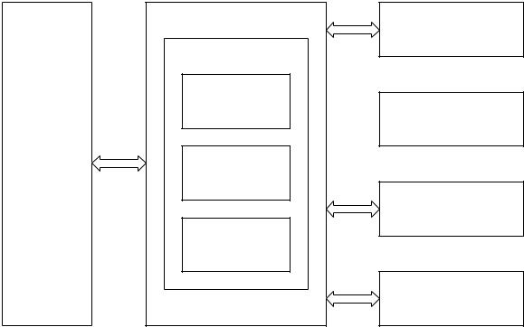
Basic operation
Major product systems
The product includes the following systems:
●Engine control system
●Laser scanner system
●Image-formation system
●Pickup and feed system
●Accessory
Figure 1-1 Product systems
LASER SCANNER SYSTEM
IMAGE-FORMATION SYSTEM
ENGINE CONTROL
SYSTEM
PICKUP, FEED AND DELIVERY SYSTEM
ACCESSORY
2 |
Chapter 1 Theory of operation |
ENWW |

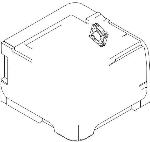
Product components
Figure 1-2 Product components
1 |
2 |
3 |
4 |
5 |
6 |
7 |
8 |
9 |
10
 11
11
12
13
14
15
16
17
|
20 |
19 |
|
18 |
|
Table 1-1 |
Product components |
|
|
|
|
|
|
|
|
|
|
Item |
|
Description |
|
Item |
Description |
|
|
|
|
|
|
1 |
|
Fuser delivery roller |
|
11 |
Multipurpose tray (Tray 1) pickup roller |
|
|
|
|
|
|
2 |
|
Face-down delivery roller |
|
12 |
Multipurpose tray (Tray 1) separation pad |
|
|
|
|
|
|
3 |
|
Pressure roller |
|
13 |
Registration roller |
|
|
|
|
|
|
4 |
|
Fuser film assembly |
|
14 |
Feed roller |
|
|
|
|
|
|
5 |
|
Fuser |
|
15 |
Tray 2 cassette pickup roller |
|
|
|
|
|
|
6 |
|
Transfer roller |
|
16 |
Tray 2 cassette separation pad |
|
|
|
|
|
|
7 |
|
Photosensitive drum |
|
17 |
Tray 2 cassette |
|
|
|
|
|
|
8 |
|
Laser scanner |
|
18 |
Duplex re-pickup roller (duplex models only) |
|
|
|
|
|
|
9 |
|
Toner cartridge |
|
19 |
Duplex feed assembly (duplex models only) |
|
|
|
|
|
|
10 |
|
Registration shutter |
|
20 |
Duplex feed roller (duplex models only) |
|
|
|
|
|
|
ENWW |
Basic operation |
3 |
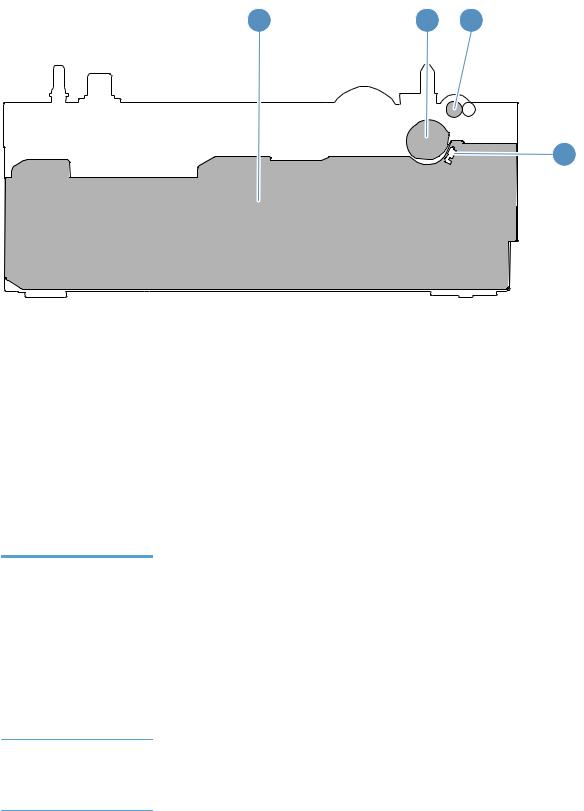
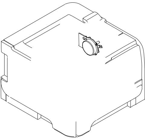
Figure 1-3 Optional Tray 3 components
1 |
2 |
3 |
4 |
Item |
Description |
Item |
Description |
|
|
|
|
1 |
Tray 3 cassette |
3 |
Tray 3 feed roller |
|
|
|
|
2 |
Tray 3 pickup roller |
4 |
Tray 3 separation pad |
|
|
|
|
Sequence of operation
The product operational sequence is controlled by the DC controller that is on the engine control system. The following table describes each period of a print operation from when the printer is turned on until the motor stops rotating.
Table 1-2 Sequence of operation
Period |
Duration |
Purpose |
Remarks |
|
|
|
|
WAIT |
From the time the power is |
Brings the product to the |
The product detects the toner |
|
turned on or the door is |
ready state |
level, cartridge presence, and |
|
closed until the drum-phase |
|
environment. |
|
adjustment is complete |
|
|
|
|
|
|
STBY (Standby period) |
From end of the WAIT or |
Maintains the product in |
The product enters sleep |
|
LSTR period until either the |
readiness for a print |
mode when the formatter |
|
print command is received |
command |
sends a sleep command. |
|
from the formatter or the |
|
|
|
power is turned off |
|
|
INTR (Initial rotation) |
From the time the print |
|
command is received until the |
|
fuser temperature reaches its |
|
target temperature |
Prepares the high-voltage biases, laser scanner, and fuser for printing
4 |
Chapter 1 Theory of operation |
ENWW |

Table 1-2 Sequence of operation (continued)
Period |
Duration |
Purpose |
Remarks |
From the end of INTR period |
|
|
until the fuser paper sensor |
|
detects the trailing edge of |
|
paper |
Forms the images on the photosensitive drum and transfers the toner image to the print media
LSTR (Last rotation) |
From the end of the PRINT |
|
period until the delivery motor |
|
stops rotating |
Moves the printed sheet out of the product, and stops the output from the laser scanner and high-voltage biases
The product enters the INTR period as soon as the formatter sends another print command.
ENWW |
Basic operation |
5 |
Engine control system
The engine control system coordinates all product functions and drives the other three systems.
The engine control system contains the DC controller, high-voltage power supply PCA, and low-voltage power supply.
Figure 1-4 Engine control system components
ENGINE CONTROL SYSTEM
LASER SCANNER SYSTEM
Engine controller
DC controller
 IMAGE-FORMATION SYSTEM
Formatter |
Low-voltage |
|
|
|
power supply |
PICKUP, FEED AND
DELIVERY SYSTEM
High-voltage power supply
ACCESSORY
6 |
Chapter 1 Theory of operation |
ENWW |
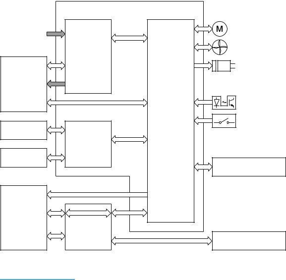
DC controller
The DC controller controls the product operational sequence.
Figure 1-5 DC controller
Engine controller
Motor
AC input
Fan
Low-voltage power supply
Solenoid
Fuser
Photointerrupter
Switch
DC controller
Transfer roller
High-voltage power supply
Cartridge
Accessory
Laser scanner assembly
Formatter
Control panel
Table 1-3 DC controller electrical components
Component type |
Symbol |
Description |
|
|
|
Fan |
FM1 |
Main fan |
|
|
|
Motor |
M1 |
Main motor |
|
|
|
|
M2 |
Scanner motor |
|
|
|
Solenoid |
SL1 |
Multipurpose tray pickup solenoid |
|
|
|
|
SL2 |
Cassette pickup solenoid |
|
|
|
|
SL3 |
Duplex reverse solenoid (duplex models only) |
|
|
|
ENWW |
Engine control system |
7 |

Table 1-3 DC controller electrical components (continued)
Component type |
Symbol |
Description |
|
|
|
Switch |
SW1001 |
Power switch |
|
|
|
|
SW301 |
Door-open detection switch |
|
|
|
Photointerrupter |
PS912 |
Top sensor |
|
|
|
|
PS913 |
Paper width sensor |
|
|
|
|
PS914 |
Cassette media out sensor |
|
|
|
|
PS914 |
Left paper width sensor |
|
|
|
|
PS915 |
Multipurpose tray media out sensor |
|
|
|
|
PS915 |
Right paper width sensor |
|
|
|
|
PS916 |
Fuser output sensor |
|
|
|
|
PS916 |
Output-bin paper-full sensor |
|
|
|
8 |
Chapter 1 Theory of operation |
ENWW |
Motor control
The product has one motor for media feed and image formation.
Figure 1-6 Main motor
Table 1-4 |
Motor control components |
|
|
|
|
|
|
Symbol |
Name |
Driving part |
Failure detection |
|
|
|
|
M1 |
Main motor |
Rollers in the product an |
Yes |
|
|
rollers in the paper feeder |
|
|
|
|
|
ENWW |
Engine control system |
9 |
Fan control
The product has one fan for preventing the product from overheating.
Figure 1-7 Fan control
Table 1-5 |
Fan control components |
|
|
|
|
|
|
|
|
Symbol |
Name |
Cooling area |
Type |
Speed |
|
|
|
|
|
FM1 |
Fan |
Inside the product |
Intake |
Full |
|
|
|
|
|
10 Chapter 1 Theory of operation |
ENWW |
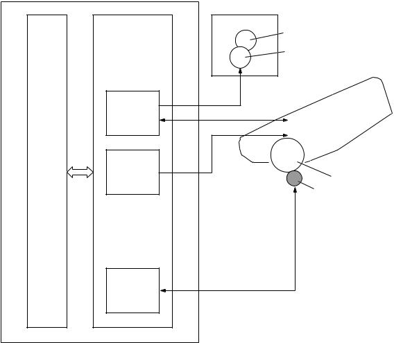
High-voltage power supply
The DC controller controls the high-voltage power supply to generate high-voltage biases. The highvoltage power supply generates the high-voltage biases that are applied to the primary charging roller, developing roller, transfer roller, and fuser film.
Figure 1-8 High-voltage power supply
Engine controller
DC controller |
High-voltage power supply |
|
|
Fuser |
|
|
|
Fuser film |
|
|
|
Pressure roller |
|
Primary |
FB |
Cartridge |
|
|
|||
|
|
||
charging |
PR |
|
|
bias circuit |
Primary charging roller |
||
|
|||
|
|
Developing roller |
|
Developing |
DV |
|
|
bias circuit |
|
Photosensitive drum |
|
|
|
||
|
|
Transfer roller |
|
Transfer |
TR |
|
|
bias circuit |
|
|
ENWW |
Engine control system 11 |
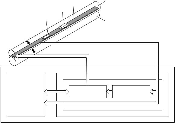
Fuser control circuit
The fuser control circuit controls the fuser temperature. The product uses an on-demand fusing method.
Figure 1-9 Fuser control circuit
Fuser film
H1
TP1
TH1
Pressure roller
FUSER TEMPERATURE signal
FUSER HEATER CONTROL signal
|
Fuser heater |
Fuser heater |
DC controller |
control circuit |
safety circuit |
|
|
|
|
Fuser control circuit |
|
|
Low-voltage power supply |
|
|
Engine controller |
|
Table 1-6 |
Fuser control circuit components |
|
|
|
|
Symbol |
Name |
Description |
|
|
|
H1 |
Fuser heater |
Heats the fuser film |
|
|
|
TH1 |
Thermistor |
Detects fuser temperature (contact type) |
|
|
|
TP1 |
Thermoswitch |
Prevents an abnormal temperature rise |
|
|
of the fuser heater (contact type) |
|
|
|
These temperature controls in the fuser are performed by the fuser heater control circuit and the fuser heater safety. They are controlled by the DC controller.
12 Chapter 1 Theory of operation |
ENWW |
Loading...