

Page 1

Designjet T9x0, T15x0 ePrinter Series and
T25x0, T3500 eMultifunction Series
Service Manual
Page 2

Edition 3, February 17, 2017
Legal notices
Warranty
© 2016 HP Development Company, L.P.
This document contains proprietary information
that is protected by copyright. All rights are
reserved. No part of this document may be
photocopied, reproduced, or translated to
another language without the prior written
consent of HP Development Company.
The information contained in this document is
subject to change without notice.
HP makes no warranty of any kind with regard
to this material, including, but not limited to, the
implied warranties of merchantability and
tness for a particular purpose.
HP shall not be liable for errors contained herein
or for incidental or consequential damages in
connection with the furnishing, performance, or
use of this material.
Page 3

Safety
The Warning symbol calls attention to a
procedure, practice, or the like, which, if not
correctly performed or adhered to, could result
in personal injury. Do not proceed beyond a
Warning symbol until the indicated conditions
are fully understood and met.
The Caution symbol calls attention to an
operating procedure, practice, or the like, which,
if not correctly performed or adhered to, could
result in damage to or destruction of part or all
of the printer. Do not proceed beyond a Caution
symbol until the indicated conditions are fully
understood and met.
Page 4

Page 5

Table of contents
1 Printer fundamentals ............................................................................................................................................................................... 1
Introduction ............................................................................................................................................................................... 2
Theory of operation ................................................................................................................................................................. 6
2 Troubleshooting ..................................................................................................................................................................................... 34
The front panel ....................................................................................................................................................................... 35
Service keys combination ..................................................................................................................................................... 37
Troubleshooting tree (T920 and T1500 only) ................................................................................................................... 39
Product Troubleshooting trees (T2500 and T3500 only) ............................................................................................... 41
Scanner Troubleshooting Tree ............................................................................................................................................ 42
Scanner CIS Troubleshooting ............................................................................................................................................... 43
Troubleshooting using board LEDs ..................................................................................................................................... 44
Paper handling problems ..................................................................................................................................................... 50
Ink supply problems .............................................................................................................................................................. 70
Print-quality problems .......................................................................................................................................................... 84
Connectivity problems ........................................................................................................................................................ 104
Scanning Problems .............................................................................................................................................................. 109
HP 727 Printhead Troubleshooting .................................................................................................................................. 111
Videos for replacing CSR parts and HP 727 printhead .................................................................................................. 113
Firmware upgrades ............................................................................................................................................................. 114
3 System error codes .............................................................................................................................................................................. 115
Introduction .......................................................................................................................................................................... 116
What to do if the front panel fails to initialize ................................................................................................................. 118
System error codes in brief ................................................................................................................................................ 121
System error codes in full .................................................................................................................................................. 124
Appendix A: How to troubleshoot system error 79:04 and 79.2:04 ........................................................................... 164
Appendix B: Updating rmware in boot mode ................................................................................................................ 176
Appendix C: Obtaining the diagnostics package ............................................................................................................. 177
ENWW v
Page 6

4 Diagnostics, Service Utilities and Calibrations ................................................................................................................................. 179
Introduction .......................................................................................................................................................................... 180
Diagnostic Tests and Utilities ............................................................................................................................................. 181
Service Utilities ..................................................................................................................................................................... 203
Service Calibrations ............................................................................................................................................................. 232
5 Parts and diagrams .............................................................................................................................................................................. 240
Introduction .......................................................................................................................................................................... 240
Printer support ..................................................................................................................................................................... 241
Center and Roll covers ........................................................................................................................................................ 242
Rear covers ........................................................................................................................................................................... 243
Cover Front Panel Side ........................................................................................................................................................ 244
Cover SVS Side ...................................................................................................................................................................... 245
Center Assemblies ............................................................................................................................................................... 246
Front Panel Side Assemblies .............................................................................................................................................. 248
SVS Side Assemblies ........................................................................................................................................................... 249
Scan Axis Assemblies .......................................................................................................................................................... 250
Paper Path Assemblies (Front) .......................................................................................................................................... 251
Paper Path Assemblies (Center) ........................................................................................................................................ 253
Stacker Parts (Rear) ............................................................................................................................................................. 255
Stacker Parts (Front) ........................................................................................................................................................... 256
Carriage Assembly ............................................................................................................................................................... 260
Electrical Parts ..................................................................................................................................................................... 261
Miscellaneous Parts ............................................................................................................................................................. 263
CIS Unit Construction ........................................................................................................................................................... 265
Scanner Control Unit ........................................................................................................................................................... 266
6 Removal and installation .................................................................................................................................................................... 269
Parts list; all models ............................................................................................................................................................ 270
Parts list; HP Designjet T2500 and T3500 eMultifunction Series only ....................................................................... 272
Parts list; HP Designjet T2500 eMultifunction Series only ............................................................................................ 273
Parts list; HP Designjet T3500 eMultifunction Series only ............................................................................................ 274
Introduction .......................................................................................................................................................................... 275
Customer Self Repair parts ................................................................................................................................................ 277
Service Calibration Guide to Removal and Installation .................................................................................................. 278
Main cover (front panel side) .............................................................................................................................................. 281
Main cover (service station side) ....................................................................................................................................... 283
Center cover (T920 only) .................................................................................................................................................... 285
Converger Assembly ........................................................................................................................................................... 287
Cleanout ................................................................................................................................................................................ 288
vi ENWW
Page 7

Output platen ....................................................................................................................................................................... 290
Fixed tray cover (Front Panel side) .................................................................................................................................... 291
Fixed tray cover (service station side) .............................................................................................................................. 292
Arch sidewall cover (front panel side) ............................................................................................................................... 293
Arch sidewall cover (service station side) ........................................................................................................................ 294
Rear cover ............................................................................................................................................................................. 295
Window Sensor .................................................................................................................................................................... 296
HP 727 Printhead installation tips and tricks .................................................................................................................. 298
Ink Service kit ....................................................................................................................................................................... 303
Open the E-Box .................................................................................................................................................................... 304
E-Box fan ............................................................................................................................................................................... 308
Jester PCA ............................................................................................................................................................................. 310
Power supply unit ................................................................................................................................................................ 311
Hard disk drive ..................................................................................................................................................................... 313
Engine PCA ............................................................................................................................................................................ 314
Formatter PCA ...................................................................................................................................................................... 315
Front panel ............................................................................................................................................................................ 318
Carriage ................................................................................................................................................................................. 322
Line Sensor ........................................................................................................................................................................... 326
Carriage PCA ......................................................................................................................................................................... 327
Rail Oiler Kit ........................................................................................................................................................................... 329
PRS Actuator ......................................................................................................................................................................... 330
Belt ......................................................................................................................................................................................... 332
Encoder Strip ........................................................................................................................................................................ 333
Scan Axis Motor .................................................................................................................................................................... 335
Drop Detector ....................................................................................................................................................................... 338
Service Station with Drop Detector ................................................................................................................................... 339
Primer Assembly .................................................................................................................................................................. 343
ISS (Ink Supply Station) Front Panel Side ......................................................................................................................... 346
ISS SVS Side .......................................................................................................................................................................... 350
Ink Tubes and Trailing Cable .............................................................................................................................................. 354
Media Sensor ........................................................................................................................................................................ 357
Bottom Rewinder Support ................................................................................................................................................. 359
Top Rewinder Support ........................................................................................................................................................ 361
Top Tip Support .................................................................................................................................................................... 363
Bottom Tip Support ............................................................................................................................................................. 364
Vertical Media Guide ............................................................................................................................................................ 366
Center Support ..................................................................................................................................................................... 368
Full Bleed ............................................................................................................................................................................... 369
Auto Pinch Lifter ................................................................................................................................................................... 370
Pinch Wheel Assembly ........................................................................................................................................................ 376
ENWW vii
Page 8

Motor Media Advance Transmission with Encoder ......................................................................................................... 379
Starwheel Motor .................................................................................................................................................................. 387
Starwheel Support ............................................................................................................................................................... 392
Second Starwheel Rail ........................................................................................................................................................ 394
Overdrive ............................................................................................................................................................................... 396
Cutter Platten ....................................................................................................................................................................... 398
Sensor Valves ....................................................................................................................................................................... 401
Valves Motor ......................................................................................................................................................................... 404
Stacker ................................................................................................................................................................................... 405
Stacker adaptor for MFP ..................................................................................................................................................... 407
Stacker Pinches .................................................................................................................................................................... 411
Stacker Hand O .................................................................................................................................................................. 412
Stacker Hand O Assy Service Kit (CR357-67041) ........................................................................................................ 413
OPTO Sensor ......................................................................................................................................................................... 417
REDI sensor ........................................................................................................................................................................... 419
OVD Transmission with Motor ........................................................................................................................................... 420
Ramps Motor ........................................................................................................................................................................ 422
Stacker Arm Sensor ............................................................................................................................................................. 424
Bump Cutter Actuator ......................................................................................................................................................... 426
How to release Service Station Caps ................................................................................................................................ 427
How to manually move Valves .......................................................................................................................................... 428
How to manually move Stacker Ramps ........................................................................................................................... 429
Scanner Controller Unit (SUP) ............................................................................................................................................ 430
CIS Tiles ................................................................................................................................................................................. 431
CIS Modules .......................................................................................................................................................................... 432
CIS FFC Cables ...................................................................................................................................................................... 433
CIS Glass ................................................................................................................................................................................ 434
Stepper Motor Assembly (taco sensor, and belt) ........................................................................................................... 435
Stepper Motor Assembly (cable) ....................................................................................................................................... 437
Paper and Lid Sensors ........................................................................................................................................................ 438
Paper and Lid Sensor Cable ............................................................................................................................................... 440
USB & Awake / Power Cable .............................................................................................................................................. 441
CIS Bridge Damper ............................................................................................................................................................... 443
CIS Scanner Latch ................................................................................................................................................................ 445
Pressure Rollers ................................................................................................................................................................... 446
Front panel side scanner cover ......................................................................................................................................... 447
Service station side scanner cover .................................................................................................................................... 448
Rear scanner cover .............................................................................................................................................................. 449
Bumper bracket ................................................................................................................................................................... 450
Deector hinge ..................................................................................................................................................................... 451
Lift assembly ........................................................................................................................................................................ 452
viii ENWW
Page 9

Scanner front beam bumper assembly ........................................................................................................................... 453
Scanner latch hook assembly ............................................................................................................................................ 454
Top scanner cover ................................................................................................................................................................ 455
Batch scanning piece ........................................................................................................................................................... 456
Card Reader Accessory ....................................................................................................................................................... 457
7 Maintenance .......................................................................................................................................................................................... 458
Preventive Maintenance ..................................................................................................................................................... 459
Preventive Maintenance Kits .............................................................................................................................................. 472
8 Customer Self Repair Flyers ............................................................................................................................................................... 473
Starwheel .............................................................................................................................................................................. 474
Cutter ..................................................................................................................................................................................... 476
Stacker arm .......................................................................................................................................................................... 478
Ink covers .............................................................................................................................................................................. 479
Leg, front-panel side ........................................................................................................................................................... 481
Leg, service-station side ..................................................................................................................................................... 484
Bottom roll cover ................................................................................................................................................................. 487
Top roll cover ........................................................................................................................................................................ 489
Carriage latch ....................................................................................................................................................................... 491
Basket .................................................................................................................................................................................... 494
Pinch arm top roll ................................................................................................................................................................ 496
Pinch arm bottom roll ......................................................................................................................................................... 497
Scanner’s glass plate .......................................................................................................................................................... 498
ENWW ix
Page 10

x ENWW
Page 11

1 Printer fundamentals
●
Introduction
●
Theory of operation
ENWW 1
Page 12

Introduction
This service manual contains information necessary to test, maintain, and service the following:
●
HP DesignJet T920 ePrinter
●
HP DesignJet T920 PostScript ePrinter
●
HP DesignJet T930 ePrinter
●
HP DesignJet T930 PostScript ePrinter
●
HP DesignJet T1500 ePrinter
●
HP DesignJet T1500 PostScript ePrinter
●
HP DesignJet T1530 ePrinter
●
HP DesignJet T1530 PostScript ePrinter
●
HP DesignJet T2500 eMultifunction
●
HP DesignJet T2500 PostScript eMultifunction
●
HP DesignJet T2530 eMultifunction
●
HP DesignJet T2530 PostScript eMultifunction
●
HP DesignJet T3500 Production eMultifunction
●
HP DesignJet T3500 Production PostScript eMultifunction
For information about using these printers, see the user's guide.
Features overview
There are 13 versions of the HP DesignJet T9x0-T15x0–T25x0–T3500 series:
●
CR354A HP DesignJet T920 36-in ePrinter
●
CR355A/B HP DesignJet T920 36-in PostScript ePrinter
●
L2Y21A HP DesignJet T930 36-in ePrinter
●
L2Y22A/B HP DesignJet T930 36-in PostScript ePrinter
●
CR356A HP DesignJet T1500 36-in ePrinter
●
CR357A/B HP DesignJet T1500 36-in PostScript
●
L2Y23A HP DesignJet T1530 36-in ePrinter
●
L2Y24A/B HP DesignJet T1530 36-in PostScript
●
CR358A HP DesignJet T2500 eMultifunction
●
CR358A/B HP DesignJet T2500 PostScript eMultifunction
●
L2Y25A HP DesignJet T2530 eMultifunction
2 Chapter 1 Printer fundamentals ENWW
Page 13
●
L2Y26A/B HP DesignJet T2530 PostScript eMultifunction
●
B9E24A/B HP DesignJet T3500 Production eMFP
NOTE: As of August 2013 there are no plans for an upgrade to enable PostScript features from non-PostScript
capabilities.
The dierent sku features are:
CR358A HP
DesignJet T2500
eMultifunction,
CR358A/B HP
DesignJet T2500
CR355A/B HP
DesignJet T920
CR354A HP
DesignJet T920
36-in ePrinter
and L2Y21A HP
DesignJet T930
Feature
Paper source One 36-in roll, and single sheets Two 36-in rolls, and single sheets
Paper output Stacker, accepting up to 50 A1 plain-paper sheets, and basket
Connectivity Gigabit Ethernet LAN (1000 base T)
36-in ePrinter
36-in PostScript
ePrinter and
L2Y22A/B HP
DesignJet T930
36-in PostScript
ePrinter
CR356A HP
DesignJet T1500
36-in ePrinter
and L2Y23A HP
DesignJet T1530
36-in ePrinter
CR357A/B HP
DesignJet T1500
36-in PostScript
and L2Y24A/B
HP DesignJet
T1530 36-in
PostScript
PostScript
eMultifunction,
L2Y25A
DesignJet T2530
eMultifunction
and L2Y26A/B
T2530 PostScript
eMultifunction
B9E24A/B HP
DesignJet T3500
Production eMFP
One USB HS host connector in the front panel, for USB ash drives
IPv4, IPv6, IPSec, TCP9100, LPR, DHCP, AutoIP/Zeroconf, Bonjour, SNMP/v3, Airprint
Web services Automatic rmware upgrade, HP DesignJet ePrint & Share, printing by email
Speed Line-drawing, fast, plain paper: 21.6 s mono or color on A1&D
Color image, normal, plain paper: 69 s on A1&D
Color image, best, glossy paper: 246 s on A1&D
Resolution Up to 2400×1200 optimized dpi from 1200×1200 input ppi
Memory 1.5GB RAM (2.5GB RAM T3500);1GB in Formatter and 512MB in Engine PCA), 320 GB hard disk (500 GB hard disk for
T1530 and T2530), 32 GB Dedicated le-processing memory, 32GB (T920 series), 64 GB (T1500 series), and 128 GB
(T2500 and T3500 series), Virtual Memory
Supplies O-axis ink cartridges:
●
Introductory supplies: 69 ml (40 ml T3500) matte black, photo black, gray, cyan, magenta, yellow
●
Replacement supplies: 69 ml / 300 ml (130 ml T3500) matte black, for other colors 40 ml / 130 ml; photo black,
gray, cyan, magenta, yellow
●
Can be replaced by the customer
One printhead for all colors:
●
9/8-in length
●
Drop size: 9 pl matte black / 6 pl other inks
●
Can be replaced by the customer
Hardware
dierentiation:
X X X X
ENWW Introduction 3
Page 14

CR358A HP
DesignJet T2500
eMultifunction,
CR358A/B HP
DesignJet T2500
CR355A/B HP
DesignJet T920
CR354A HP
DesignJet T920
36-in ePrinter
and L2Y21A HP
DesignJet T930
Feature
Second roll X X X X
36-in ePrinter
36-in PostScript
ePrinter and
L2Y22A/B HP
DesignJet T930
36-in PostScript
ePrinter
CR356A HP
DesignJet T1500
36-in ePrinter
and L2Y23A HP
DesignJet T1530
36-in ePrinter
CR357A/B HP
DesignJet T1500
36-in PostScript
and L2Y24A/B
HP DesignJet
T1530 36-in
PostScript
PostScript
eMultifunction,
L2Y25A
DesignJet T2530
eMultifunction
and L2Y26A/B
T2530 PostScript
eMultifunction
B9E24A/B HP
DesignJet T3500
Production eMFP
Borderless
printing on roll
photo media
Other
dierentiations:
Languages
supported
Virtual Memory
[GB]
1 job in queue
(last job reprint)
Job queues X X X X X
Job preview from
queue
Crop marks and
nesting
EWS job
submmital
X X X X
X X X X
HP-GL/2, HPRTL, TIFF, JPEG,
CALS G4, HP PCL
3 GUI, URF
32 32 64 64 128 128
X
Adobe PostScript
3, Adobe PDF
1.7ext3 HPGL/2, HP-RTL,
TIFF, JPEG, CALS
G4, HP PCL 3 GUI,
URF
X X X X X
HP-GL/2, HPRTL, TIFF, JPEG,
CALS G4, HP PCL
3 GUI, URF
X X X X
X X X X
Adobe PostScript 3, Adobe PDF 1.7ext3 HP-GL/2, HPRTL, TIFF, JPEG, CALS G4, HP PCL 3 GUI, URF
Job on-hold for
media
(mummify)
Auto rotate,
automatic blank
area removal
Accounting in
EWS
X X X X X X
X X X X X
X X X X
Readership
The procedures described in this service manual are to be performed by HP Certied service personnel only.
4 Chapter 1 Printer fundamentals ENWW
Page 15

Part numbers
Part numbers for printer service parts are located in Parts and diagrams on page 240.
Warning labels
Electric shock hazard
Hazardous voltage inside the printer (built-in power supply) could result in death or serious personal
injury. See the installation instructions before connecting power. Ensure that the input voltage is within
the printer's rated voltage range. Use only earthed mains outlets and the power cords supplied by HP
with the printer. There are no operator-serviceable parts inside the printer. Refer servicing to qualied
service personnel. Disconnect the power cord before servicing. Voltage is still present in the built-in
power supply after the main switch is turned o.
Double pole/neutral fusing
Electric shock hazard. The built-in power supply incorporates a fuse on each conductor, therefore the
printer could be energized even when one fuse has blown. There are no operator-replaceable fuses
inside. Refer servicing to qualied service personnel. Disconnect the power cord before servicing.
ENWW Introduction 5
Page 16
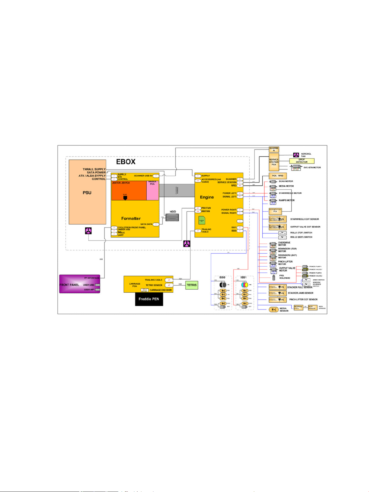
Theory of operation
Schematics
Electronics are based on 3 main components:
●
E-box - contains the power supply and all the PCAs (driving the printer), plus the Ethernet port.
●
Carriage PCA - drives the printhead.
●
Front Panel - user interface and USB port.
The following diagram describes the connections between components and electronic boards and the data line
type for T920, T1500 and T2500.
Block Diagram
(HP DesignJet T3500 eMultifunction Series only)
6 Chapter 1 Printer fundamentals ENWW
Page 17
ENWW Theory of operation 7
Page 18
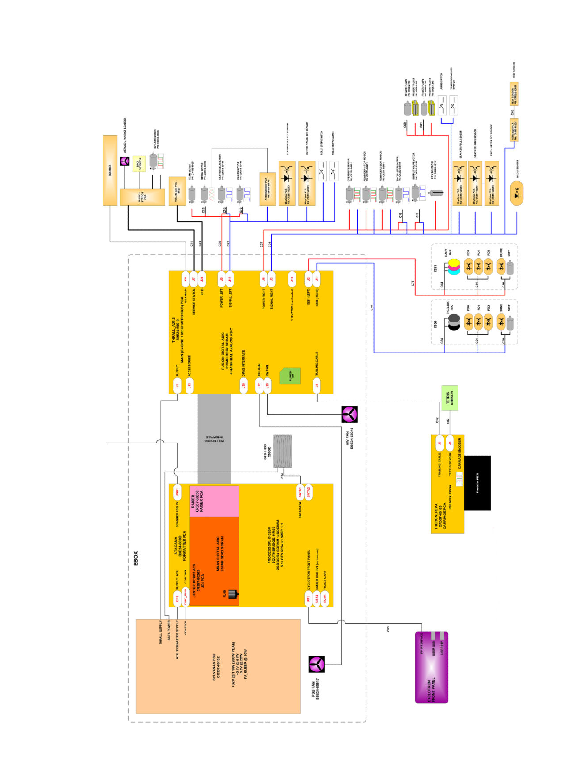
Block Diagram
(HP DesignJet T2500 and T3500 eMultifunction Series only)
Wiring Diagram
(HP DesignJet T2500 and T3500 eMultifunction Series only)
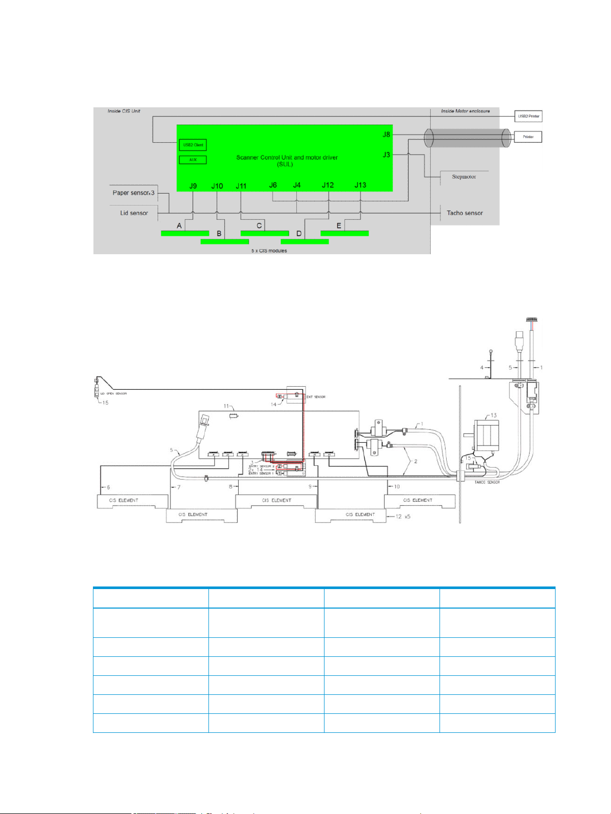
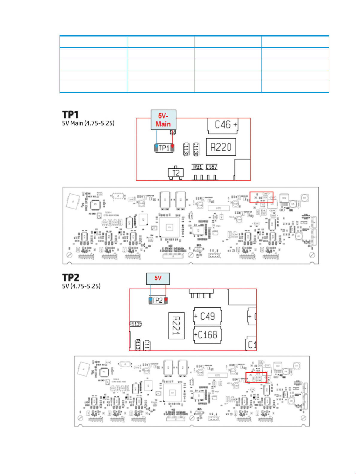
Scanner Controller Board Layout (SULG)
(HP DesignJet T2500 and T3500 eMultifunction Series only)
Voltage Min limit Max limit
TP1 5V-Main (Always on when there
is power to the board)
TP2 5V 4.75 5.25
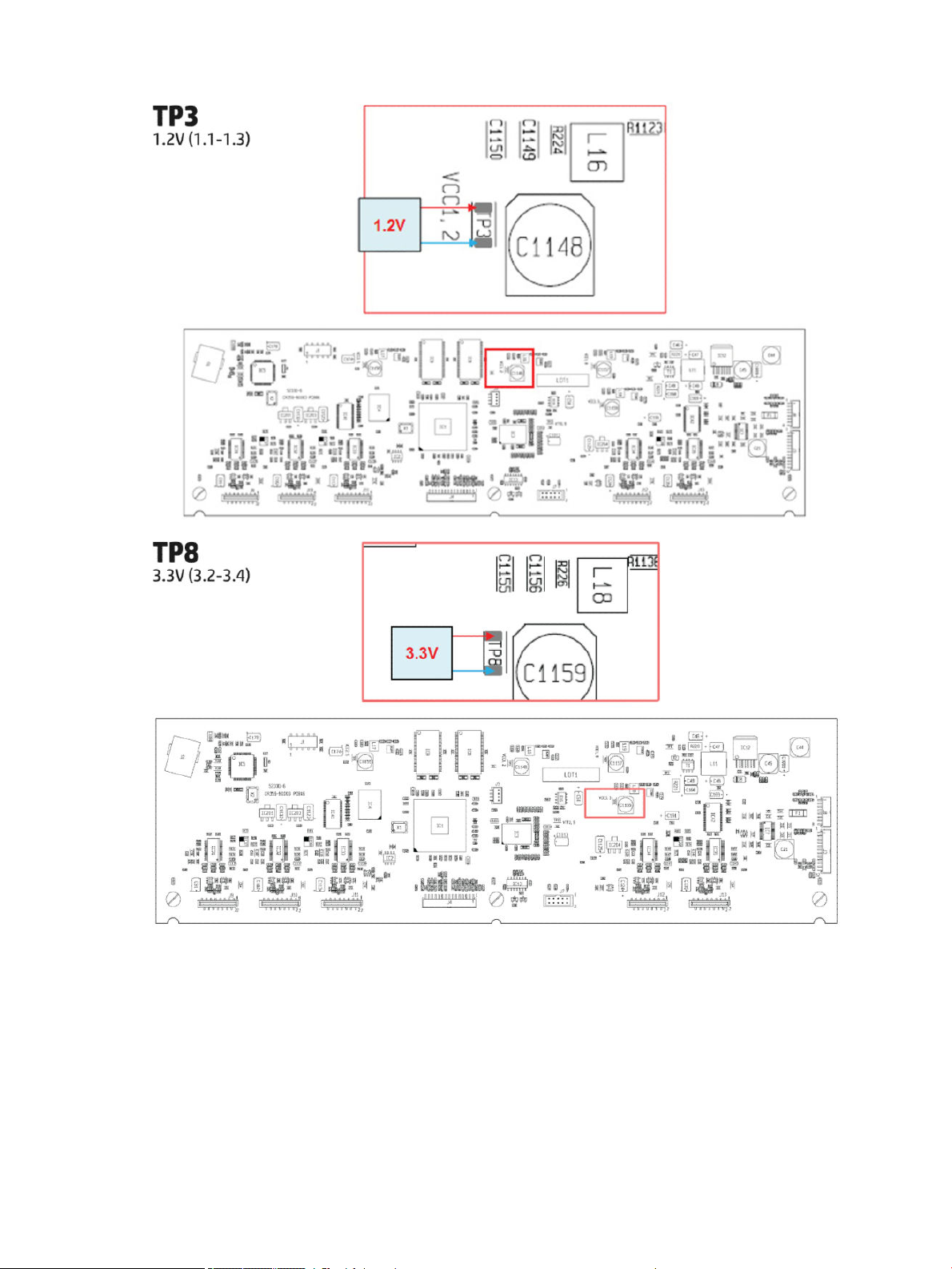
TP3 1.2V 1.1 1.3
TP8 3.3V 3.2 3.4
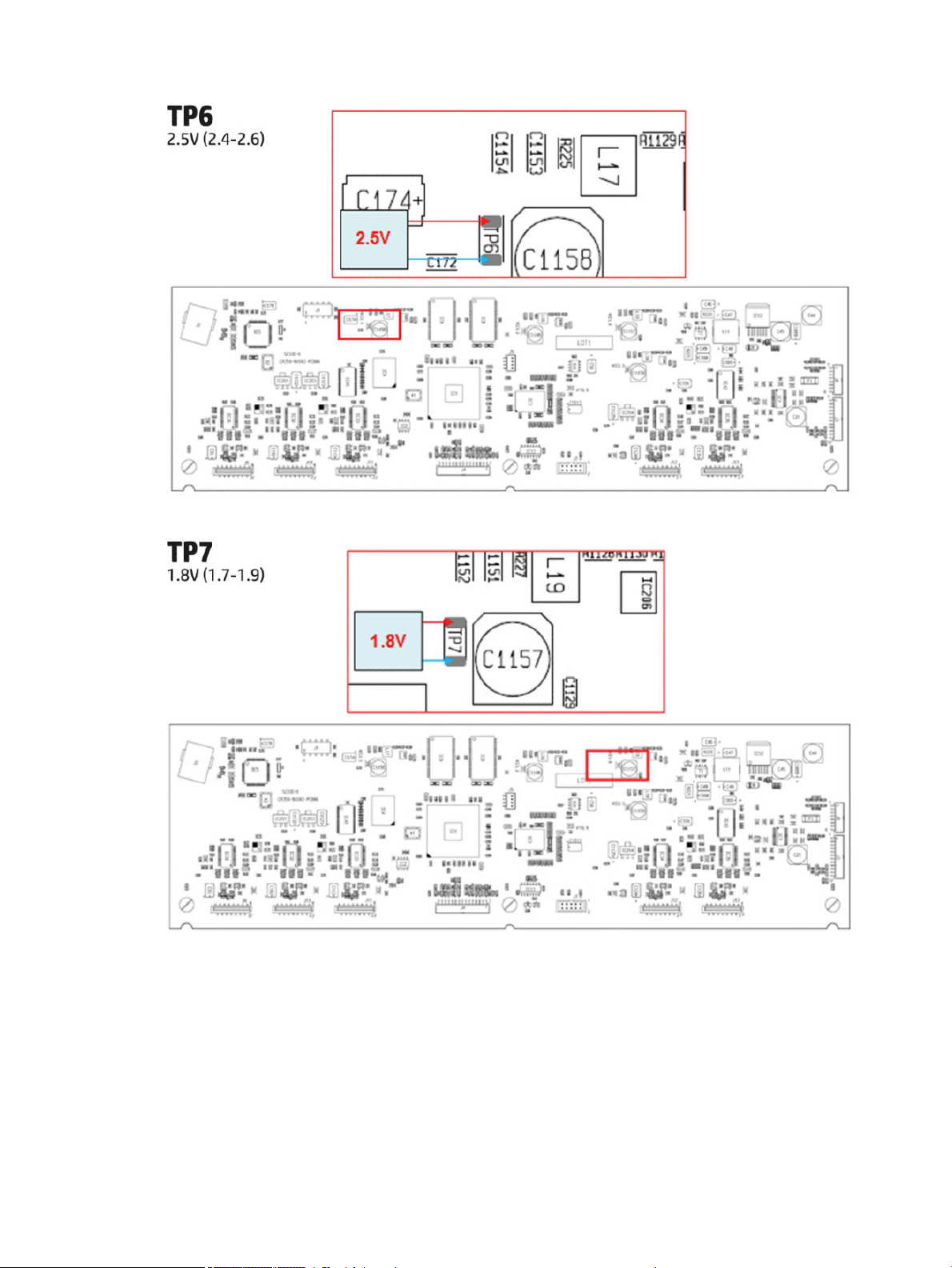
TP6 2.5V 2.4 2.6
TP7 1.8V 1.7 1.9
8 Chapter 1 Printer fundamentals ENWW
4.75 5.25
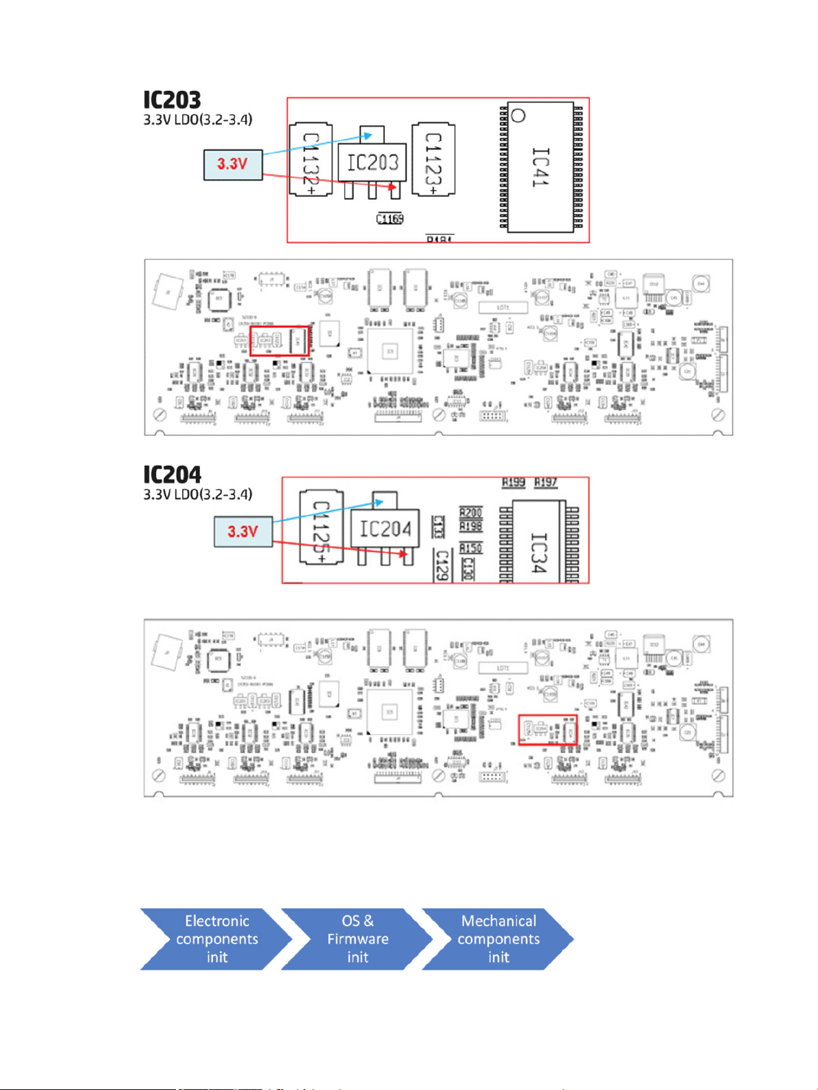
Page 19
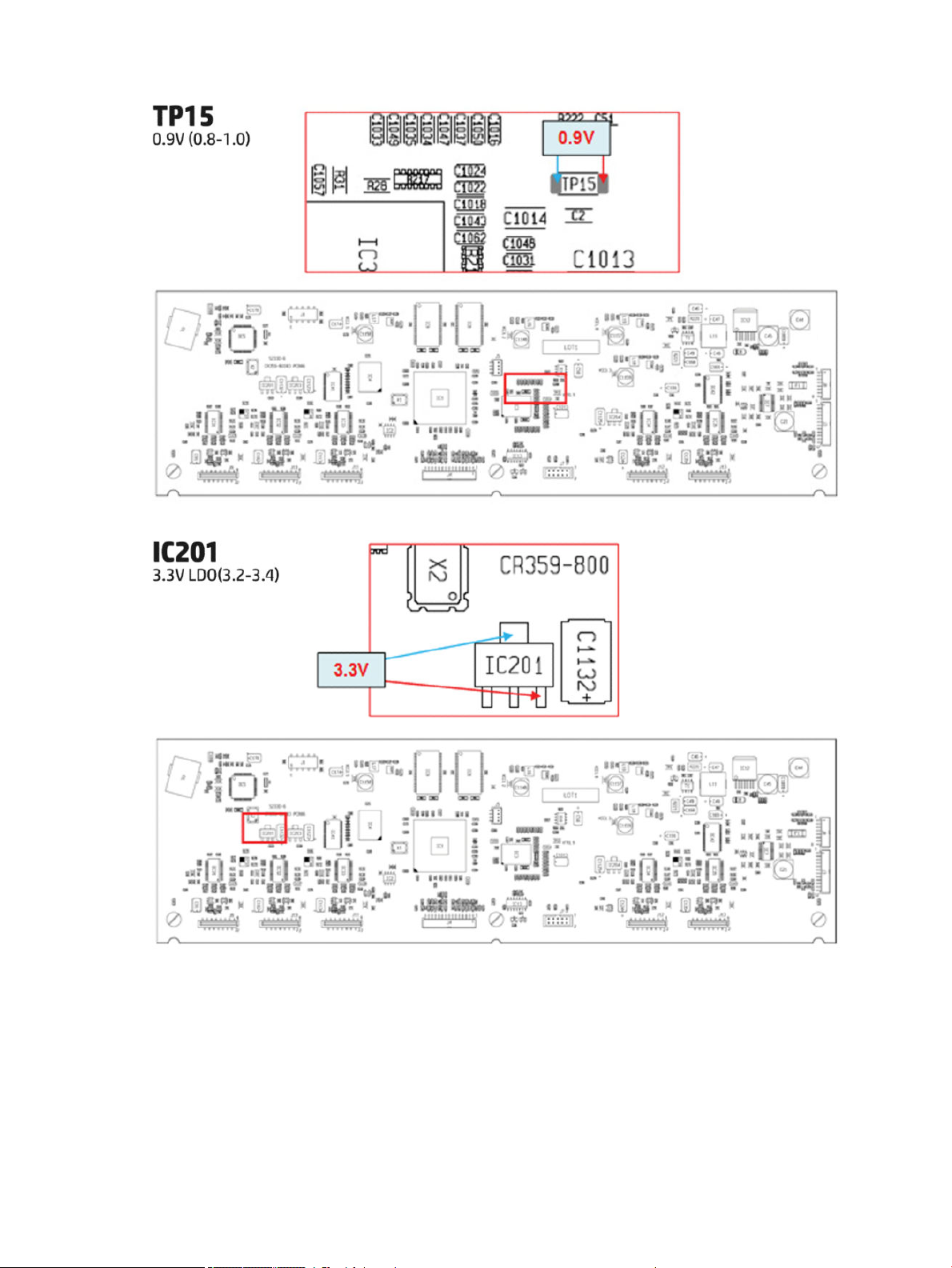
Voltage Min limit Max limit
TP15 0.9V 0.8 1.0
IC201 3.3VLDO 3.1 3.5
IC203 3.3VLDO 3.1 3.5
IC204 3.3VLDO 3.1 3.5
ENWW Theory of operation 9
Page 20
10 Chapter 1 Printer fundamentals ENWW
Page 21
ENWW Theory of operation 11
Page 22
12 Chapter 1 Printer fundamentals ENWW
Page 23
Printer Initialization
There are 3 main blocks to be initialized before the printer can be operated:
ENWW Theory of operation 13
Page 24
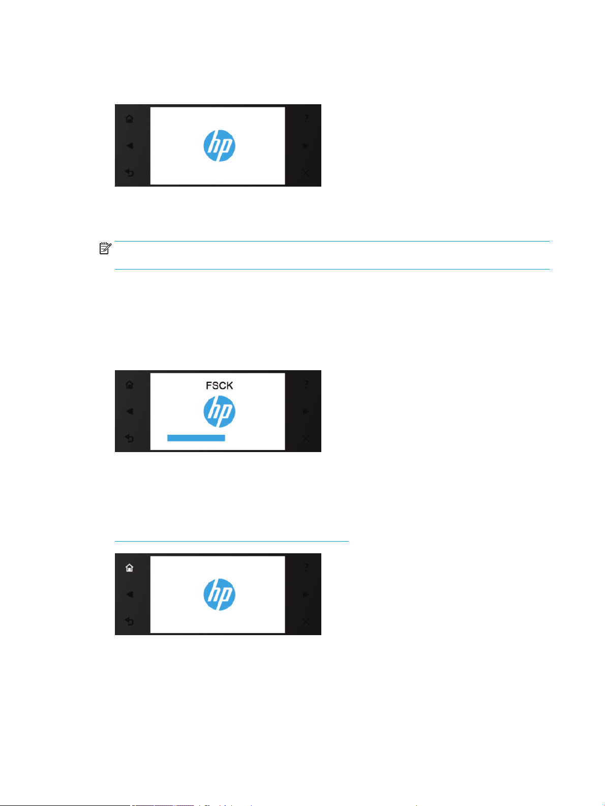
Electronic components init
1. The front panel shows a white background and blue HP logo.
2. The upper LED in the formatter is ON, indicating that the formatter has been initialized.
3. The middle LED in the formatter blinks, indicating that the HDD has been initialized.
NOTE: Steps 2&3 are the same when waking from Sleep Mode except the 3 LEDs are not on but; ON-
Blinking-OFF
OS & Firmware init
1. The OS is loaded into RAM. The Front Panel blinks for a second.
2. If boot up is after a bad power-o, the boot sequence automatically runs a le system check.
a. The Front Panel shows the FSCK, text.
b. First, FSCK runs on the root partition.
c. If FSCK is successful, the OS boots up from the root partition and runs FSCK on the data partition.
3. After FSCK, the OS nishes booting from the HDD.
4. The home button lights up to allow stopping the boot sequence, and entry to the diagnostics menu, see
Diagnostics, Service Utilities and Calibrations on page 179.
Mechanical components init
1. The Front Panel shows a black background with a blue circle in the middle. The “Initializing” message
appears. A progress bar shows the percentage of subsystems that have been initialized.
2. The printer moves the carriage from side to side to validate its position within the scan axis. The printer
initializes the service station, moving the caps from bumper to bumper.
14 Chapter 1 Printer fundamentals ENWW
Page 25
3. The pinches move down into position.
4. T2500 and T3500 only: The printer will initialize the Scanner and start checking it.
5. The carriage and service station move to the home position
6. The printer checks the status of supplies and the printhead, and then initializes the Ink Supply Stations.
7. Servicing routines are launched. The routines refresh the printhead depending on the time that the printer
has been o. The Front Panel shows “Preparing Print System”.
8. The paper path subsystems are initialized by exercising the ramps and rewinder, checking if there is media
present over the Media Sensor.
9. At the end of the process, the home screen appears in the Front Panel.
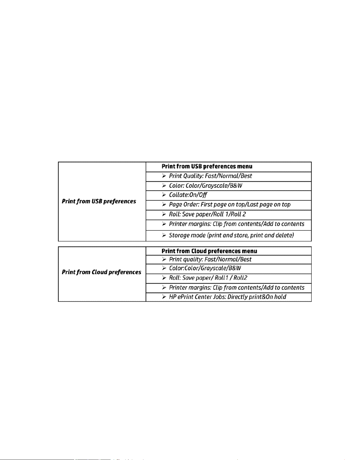
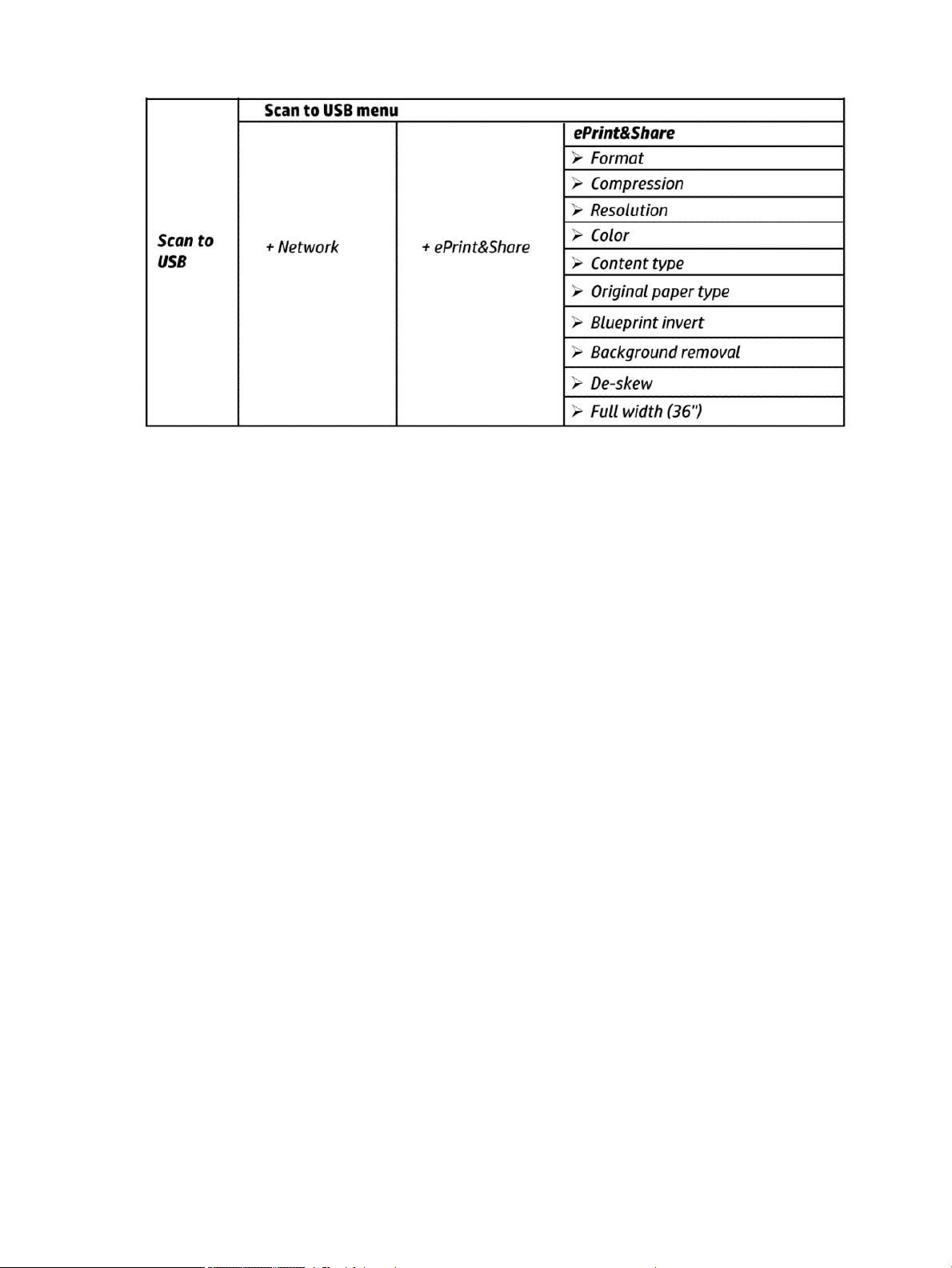
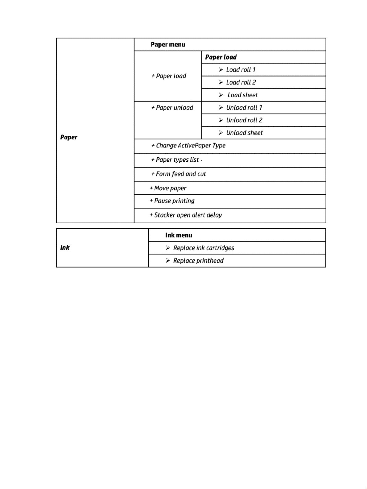
Front Panel Menu Map
The following tables show the front panel menu layout.
ENWW Theory of operation 15
Page 26
16 Chapter 1 Printer fundamentals ENWW
Page 27

ENWW Theory of operation 17
Page 28

18 Chapter 1 Printer fundamentals ENWW
Page 29

ENWW Theory of operation 19
Page 30
20 Chapter 1 Printer fundamentals ENWW
Page 31

ENWW Theory of operation 21
Page 32

22 Chapter 1 Printer fundamentals ENWW
Page 33

ENWW Theory of operation 23
Page 34

24 Chapter 1 Printer fundamentals ENWW
Page 35

ENWW Theory of operation 25
Page 36

26 Chapter 1 Printer fundamentals ENWW
Page 37

Front Panel Menu Map (T3500 only)
ENWW Theory of operation 27
Page 38

HP 727 Printhead Start-up process
1. Insert cartridges: If the printhead is initialized during the installation of the printer, the printer will rst
check for new supplies.
28 Chapter 1 Printer fundamentals ENWW
Page 39

“Ink cartridge missing. Install ink cartridge.”
”Change cartridges now. Press OK to continue.”
If the printer still needs to purge the ink tubes and there are cartridges already installed in it, the printer will
reject the supplies, reporting them as “Not Valid” and will request to “remove and reinsert” the supplies.
Cartridges can be reseated in order to be accepted by the printer before the tubes are purged. This allows
the printer to do a full validation of the supply before running a tube purge.
If the cartridges used for installation do not contain the required 60cc of ink for purging, the printer will
report that “cartridge is not valid for setup”.
NOTE: keep in mind that to initialize a printhead you need 40ml of Matte Black ink and 30ml of ink for the
rest of the colors. To purge ink tubes, you need 60cc of all colors. If in doubt, use 130ml cartridges.
ENWW Theory of operation 29
Page 40

2. After inserting the cartridges, the printer requests the printhead.
“Preparing for printhead replacement”
“Open window to access printheads or press Cancel to quit”
NOTE: If printhead insertion is completed during printer installation, remember to remove the orange
caps.
3. After inserting the printhead, the printer will check electronic connections. If the check fails, the printer will
ask to reseat the printhead.
“Checking printheads. Please wait”
30 Chapter 1 Printer fundamentals ENWW
Page 41

4. Once it is certain that the printhead is recognized, the printer will purge the ink tubes if they are empty. It
will also ll the printhead.
“Preparing the printhead for rst usage”
If the process nishes OK, the printer will ag the printer tubes and printhead as lled with ink.
If during the process the printer detects that a cartridge has been removed it will show the message “A
supply has been removed” and it will go back to step 1.
After this step, all ink tubes should be completely lled. The circles on top of the printhead should also look
lled.
5. At this point, the printer will run 2 checks to validate the start-up: rst will check for ink pressure and
second for printhead temperature while spitting. If the pressure fails, it will be logged as a SE 93.0.n:10 in
the service plot (where n is the failing color). If the temperature check fails, it will be logged as a SE 93.2.n:
10 in the service plot (where n is the failing color). The SE are not shown in the front panel. In both cases,
the printer will request to Reseat the printhead. After the reseat the printer will try to
and printhead by going to step 3.
ll again the tubes
n indicates the missing color:
●
n=0 stands for photo black
●
n=1 stands for gray
●
n=2 stands for matte black
●
n=3 stands for cyan
●
n=4 stands for magenta
●
n=5 stands for yellow
6. After this second trial, the pressure and temperature tests will be repeated. If the pressure fails, it will be
logged as a SE 93.1.n:10 in the service plot (where n is the failing color). If the temperature check fails, it
will be logged as a SE 93.3.n:10 in the service plot (where n is the failing color). The SE are not shown in the
front panel. In any case, the printer will move to step 3 and try to execute it.
ENWW Theory of operation 31
Page 42

7. After the printhead and tubes are lled, the printer completes some printhead servicing to nalize the
initialization.
“Preparing print system”
If successful. If the printhead is properly initialized, the printer shows the following message:
“Printhead replacement. Printhead successfully replaced. Press OK to continue.”
If unsuccessful. If there is a problem the printer, depending on the problem, one of the two following
messages appears:
“Replace printhead. The printhead failed to complete the replacement process. Replace printhead. Press
OK to continue with printhead replacement.”
“Reseat the printhead. Press OK to continue.”
32 Chapter 1 Printer fundamentals ENWW
Page 43

CIS Technology
Example of a CIS Element, Contact Image Sensor:
The CIS Element consist of 3 major parts:
●
Sensor
●
Lens
●
Light source
The Light source is 3 RGB LEDs that are lit one at a time. The sensor consists of 10368 individual monochrome
sensors.
The purpose of the lens is to channel the light from the “pixels” on the image to the sensors. There is no
magnication in the lens (1x1).
Due to the very short focal length, the focus depth is limited. The original has to be in contact with the surface of
the glass plate in order to be in focus.
The LED’s ash one at a time, capturing one color at a time.
ENWW Theory of operation 33
Page 44

2 Troubleshooting
●
The front panel
●
Service keys combination
●
Troubleshooting tree (T920 and T1500 only)
●
Product Troubleshooting trees (T2500 and T3500 only)
●
Scanner Troubleshooting Tree
●
Scanner CIS Troubleshooting
●
Troubleshooting using board LEDs
●
Paper handling problems
●
Ink supply problems
●
Print-quality problems
●
Connectivity problems
●
Scanning Problems
●
HP 727 Printhead Troubleshooting
●
Videos for replacing CSR parts and HP 727 printhead
●
Firmware upgrades
34 Chapter 2 Troubleshooting ENWW
Page 45

The front panel
The front panel is located on the front right of the printer. It gives you complete control of your printer: from the
front panel, you can print, view information about the printer, change printer settings, perform calibrations and
tests, and so on. The front panel also displays alerts (warning and error messages) when necessary.
For more information about front panel, refer to the users guide.
Sleep mode
Sleep mode puts the printer into a reduced power state after a period of inactivity, turning o the front panel
display to save energy. Printer features can be enabled from this mode, and the printer maintains network
connectivity, waking up only as necessary. The printer can be woken from sleep mode by the Power button, by
sending a print job, or by opening the window, the roll cover, or the stacker cover. The printer wakes up in several
seconds, more quickly than if it is completely turned o. While in sleep mode, the Power button blinks.
To change the time that elapses before sleep mode, press , then , then Setup > Front panel options
> Sleep mode wait time. You can set a time between 5 and 240 minutes; the default time is 30 minutes.
Printer Monitoring (with thde Print Spooler) and Remote Printer Management with the HP Utility and Web
JetAdmin continue to be available during sleep mode. Some remote management tasks oer the option of
remotely waking up the printer if needed to perform the task.
Other Power States
Besides sleep mode, the printer has 5 dierent power states (including ready and sleep). Depending on the
power state, the printer has dierent subsystems wake up and ready for use.
ENWW The front panel 35
Page 46

(1) After 50 cycles of sleep-mode, the printer performs an auto-reboot, done between 22h00 and 06h00.
Background information
* Assumes printer is never switched o.
** Total DECC equiv. CO2 footprint of all IB during 5 years May-2013 / May-2018 assuming 20%, switches-o
printer or oce power and 33% programs schedule on/o.
Auto-o
Auto-o sets the printer to "soft-o" mode after the period of time set by the user can in the Front Panel. This
feature is disabled when the printer is connected to the LAN, and in this case, the printer can't go to soft-o
automatically. The default value from factory for the Auto-o time out is 120min.
NOTE: In some situations this can be confusing since printers without LAN will be set to o automatically
during the night. Furthermore, once the printer has been switched o automatically it needs to be turned on with
the Blue Power Button on the printer. Switching on from the rear button will not wake up the printer.
36 Chapter 2 Troubleshooting ENWW
Page 47

Service keys combination
Entering the User Diagnostics Menu
1. Go to Printer Main Menu.
2. Go to Diagnostics Menu.
3. Type code “1714”.
4. Go to Diagnostic Tests.
5. Allow the printer to reboot.
Printer will remain in “User Diagnostics Menu” until it’s setup to go back to Printer mode.
To go back to Printer mode:
1. From “User Diagnostics Menu” go to “Reboot in printer mode”.
2. Allow the printer to reboot.
The “User Diagnostics Menu” has a limited set of Diagnostics and allows only to perform the following actions:
●
Scan Axis Motor on page 335
●
Paper Drive Test on page 186
●
Electronics Module Test on page 187
●
Sensors Test on page 191
●
Stacker Jam Sensor Test on page 196
●
Stacker Capacity Sensor Test on page 196
●
Stacker Empty Sensor Test on page 191
●
Output Valve Test on page 192
●
Pinches Lifter Test on page 194
●
Stacker Ramps Test on page 194
●
Stacker Overdrive Test on page 195
●
Ink Delivery System (IDS) Test on page 196
●
Service Station with Drop Detector on page 339
●
Enable I/O Interfaces Utility on page 200
●
Unit Information Utility on page 200
Entering the Diagnostics Menu when booting the printer
1. Make sure the product is switched o with the Power button on the side of the Front Panel, and not with
the power switch on the back of the product.
2. Press and release the Power key to switch on the product.
ENWW Service keys combination 37
Page 48

3. Wait for the Home button light to come on.
4. Press the Home button; the button will acknowledge by blinking.
5. All LEDs will come on; press and release them one after another:
●
The Cancel icon
●
The Home icon
●
The Help icon
NOTE: Do not push the icons all at the same time, push each one in the order shown above and release
each icon before pressing on the next icon
6. The 6 buttons on the Front Panel then blink 4 times; wait until the product completes the initialization
sequence and shows the Diagnostics menu.
7. In the Diagnostics menu, scroll up and down sliding a nger vertically on the Front Panel, and press on the
desired option.
NOTE: The Diagnostic Tests and Utilities work in a special mode that does not require the full initialization of
the product. Therefore, whenever a test is nished a test, switch o the product and switch it on again before
printing, or executing another test.
NOTE: A quick press of a button on the Front Panel frame may not be recognized by the product. When
pressing a button, be sure to press it for about 1 second.
NOTE: If the product hangs up during a test; switch the product o and restart from step 1.
Entering the service utilities menu
1. From the home screen, select the Information icon in the top left corner. For information about the Front
Panel keys, see using The front panel on page 35 or:
2. From the product information area, press the main menu / tool icon on the bottom right corner of the
screen.
3. Scroll down to the lowest menu option and select the Service menu option.
4. Enter the 4-digit 1st level access code “3174” and press OK.
5. Select the Service utilities menu option.
6. From the service utilities menu you can scroll up and down to see all the available utilities. Press on the
selected menu option.
38 Chapter 2 Troubleshooting ENWW
Page 49

Troubleshooting tree (T920 and T1500 only)
As a general approach, the following tree should be followed to troubleshoot any issue. This helps understand at
which point the problem was caused. The tree is sequential; before checking a subsystem, the previous steps
need to be working. Once a sub system is identied as causing the problem, the service and utilities related to
that component can be used to troubleshoot further. See Diagnostics, Service Utilities and Calibrations
on page 179.
ENWW Troubleshooting tree (T920 and T1500 only) 39
Page 50
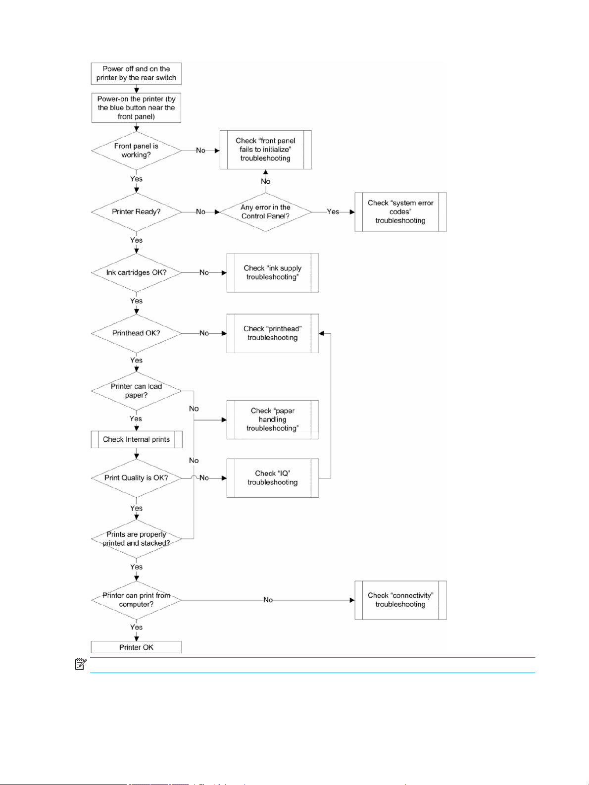
NOTE: Once an issue is conrmed, check that printer has latest rmware installed.
40 Chapter 2 Troubleshooting ENWW
Page 51
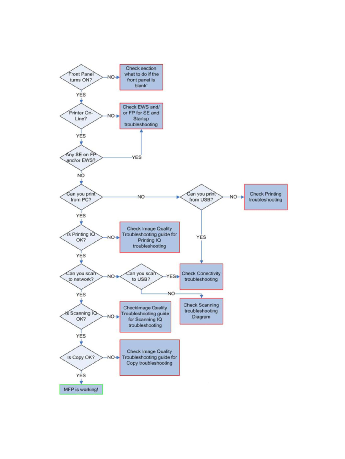
Product Troubleshooting trees (T2500 and T3500 only)
Figure 1-1 Troubleshooting
ENWW Product Troubleshooting trees (T2500 and T3500 only) 41
Page 52

Scanner Troubleshooting Tree
Figure 1-2 Scanner Troubleshooting
42 Chapter 2 Troubleshooting ENWW
Page 53

Scanner CIS Troubleshooting
Figure 1-3 Scanner Troubleshooting
ENWW Scanner CIS Troubleshooting 43
Page 54

Troubleshooting using board LEDs
All the printer boards have diagnostic LEDs to help in the troubleshooting. Although some LED information is
redundant and also known by the printer rmware, using the board LEDs can be very useful when trying to
diagnose power or communication problems. The following sections provide information on the physical location
and meaning of each board’s diagnostic LEDs.
For further information regarding electric and electronic interactions, see the subsystems’ block diagrams in
section Theory of operation on page 6.
Board name: Formatter PCA
Meaning of LEDs:
44 Chapter 2 Troubleshooting ENWW
Page 55

ENWW Troubleshooting using board LEDs 45
Page 56

46 Chapter 2 Troubleshooting ENWW
Page 57

Board name: Carriage PCA
Meaning of LEDs:
State Orange LED DS3 Orange LED DS4 Red LED DS1 Orange LED DS2
32V Power input OFF OFF ?? ?? ??
Vcc Power OFF ?? OFF OFF OFF
32V Power input ON ON ?? ?? ??
Vcc Power ON ?? ON ?? ??
FPGA not programmed ?? ON ON ON
FPGA programmed in
Reset State
FPGA out of reset but no
clock
FPGA out of reset, HCI
clock OK, HCI not
initialized
FPGA out of reset, HCI
clock OK, HCI Id initialized
FPGA out of reset, PLL
unlocked
?? ON OFF OFF
?? ON Regular blinking Not blinking
?? ON ?? Slow blinking
?? ON ?? Fast blinking
?? ON Two-pulse blinking ??
ENWW Troubleshooting using board LEDs 47
Page 58

Board name: Jester PCA
Meaning of LEDs:
There is only one LED left on Jester. It is a Green/Red LED able to code the following states:
Board status LED status Period
Some Voltage/Temperature out of range Fix Red -
Monokhan does not respond (possibly in
reset)
Mismatching Hardware/Software version Quick Red 5 Hz
Monokhan unexpected reset Fix Green -
Normal operation Quick Green 5 Hz
Slow Red 0.4 Hz
48 Chapter 2 Troubleshooting ENWW
Page 59

Board name: Engine PCA
Meaning of LEDs:
State Green LED DS5 Green LED DS11
32V Power input OFF O O
32V Power input ON On O
Sleep mode activated O On
ENWW Troubleshooting using board LEDs 49
Page 60

Paper handling problems
●
The paper has jammed in the print platen
●
The paper has jammed in the stacker
●
Thin paper is jamming in the stacker
●
High density plots jamming in the stacker
●
Several stacker paper jams
●
Stacker capacity lower than expected
●
The stacker detects "Stacker is full" permanently
●
The stacker detects "Stacker jam" permanently
●
The printer rejects the paper during paper load
●
Prints do not fall neatly into the basket
●
Using the stacker
●
The paper type is not in the list
●
The printer printed on the wrong paper type
●
An “on hold for paper” message
●
The printer displays out of paper when paper is available
●
The print remains in the printer after printing has completed
●
The cutter does not cut well
●
The roll is loose on the spindle
●
The roll is unloaded unexpectedly
The paper has jammed in the print platen
When a paper jam occurs, you normally see the Possible paper jam message in the front panel display, and a
system error 81:01 or 86:01.
1. Open the window.
50 Chapter 2 Troubleshooting ENWW
Page 61

2. Move the carriage manually to the left side of the printer, if feasible.
3. Go to the paper path.
ENWW Paper handling problems 51
Page 62

4. Cut the paper with a pair of scissors.
5. Open the roll cover.
52 Chapter 2 Troubleshooting ENWW
Page 63

6. Manually rewind paper onto the roll.
ENWW Paper handling problems 53
Page 64

7. If the leading edge of the paper is ragged, trim it carefully with scissors.
NOTE: In the T3500 the guide can be used for cutting.
54 Chapter 2 Troubleshooting ENWW
Page 65

8. Remove the paper left in the printer.
9. Make sure you have removed every fragment of paper.
IMPORTANT: Remove remaining paper by carefully pulling it out in the direction of the paper axis.
ENWW Paper handling problems 55
Page 66

10. Close the window and the roll cover.
11. Restart the printer by holding down the power button for a few seconds, or by turning the power switch at
the rear o and then on.
12. Reload the roll, or load a new sheet.
NOTE: If you nd that there is still some paper causing an obstruction within the printer, restart the procedure
and carefully remove all pieces of paper.
The paper has jammed in the stacker
When a stacker jam is detected, printing is paused, and the front panel asks you to open the stacker cover and
clear the jam by pulling out the paper.
IMPORTANT: Remove remaining paper by carefully pulling it out in the direction of the paper axis.
When the stacker arms cover is closed and the printer detects no jammed paper, the front panel requests
conrmation to continue printing.
Thin paper is jamming in the stacker
When using a media thinner than 75gsm, the blue lever needs to be pulled forwards so that there is a larger gap
between the arms and stacker tray when the arms are closed.
56 Chapter 2 Troubleshooting ENWW
Page 67

After printing with thin media, remember to return the blue lever so that there is a small gap between the arms
and stacker tray.
High density plots jamming in the stacker
If you are printing high-density plots (over 15ngrs ink density) with media below 80grs/m2, and you encounter
that plots have problems curving at the end of the stacker, or do not stack properly, and cause jams:
●
Use Manual mode.
●
Print to the basket.
●
Use thicker media; over 80grs/m2.
ENWW Paper handling problems 57
Page 68

●
Use the CR357-67089 “Stacker tray ller” (CSR)
To improve the performance of the stacker when printing high density graphic content customers can use
the “Stacker tray ller” that guides stacker paper exit.
Place the parts of the Stacker tray ller as illustrated below:
Several stacker paper jams
Call agent:
1. Ask customer for Media type used and plot content.
2. Ask customer to check there is free space between top of the stacker and the wall.
3. Ask customer to check if one or several wheels of the arms cover is stuck in the paper path.
4. Exclude the cause to be any of the previously described issues. See Thin paper is jamming in the stacker
on page 56 and High density plots jamming in the stacker on page 57.
A root cause can be one or several wheels of the arm cover stuck in the paper path.
Ask the customer to perform the following actions:
5. Check that no cable routing is blocking the paper path.
6. Remove all paper from the stacker.
7. Detach the stacker arms cover from the printer.
8. Visually check that there are no missing wheel supports in the stacker cover (there are 25 wheel supports).
9. Shake the stacker cover a couple of times so all the wheel supports can move freely.
10. Ensure that all wheel supports in the cover can rotate freely (by pushing them, and checking that they
return to their position). If any of them are stuck, try to move slightly to free them.
11. If any of the wheel supports are stuck or are missing, send a new stacker arms cover to the customer.
12. If all the wheel supports are free and there are none missing, then arrange an on-site visit with a new
stacker and stacker cover arms.
Service engineer:
Items required:
Take a stacker
Take stacker cover arms
58 Chapter 2 Troubleshooting ENWW
Page 69

1. Remove all paper from the stacker.
2. Detach the stacker cover from the printer.
3. Visually check that there are no missing wheel supports in the stacker cover (there are 25 wheel supports).
4. Shake the stacker cover a couple of times so all the wheel supports can move freely.
5. Ensure that all wheel supports in the cover can rotate freely (by pushing them, and checking that they
return to their position). If any of them are stuck, try to move slightly to free them.
6. If any of the wheel supports are stuck or are missing, send a new stacker arms cover to the customer.
7. If all the wheel supports are free and there are none missing, check that there are no free or misplaced
pieces at the bottom of the stacker (pinches, rst wheel holder, wheels, etc.).
ENWW Paper handling problems 59
Page 70

8. Check that Ramps are broken are not broken and are aligned.
9. Report root cause in cso and change Stacker.
Stacker capacity lower than expected
Stacker capacity is dened as up to 50 pages (T920/T1500/T2500), and 100 pages (T3500), A1/D size line
drawing plots in landscape on bond media, but stacker capacity depends on media thickness and page size. If
you are printing plots shorter than A1 and you experience a reduction in the stacker capacity because they
collapse and the curling lls the available stacking space:
●
Try to increase the length of the plots when printing A2 and A3 sizes:
60 Chapter 2 Troubleshooting ENWW
Page 71

–
Print A2 sizes in portrait position, using low-width rolls or nesting to minimize waste of paper.
–
For A3 size, group dierent jobs in the same plot.
The stacker detects "Stacker is full" permanently
Even when there are no pages in the stacker, it detects that is it full.
●
Remove the stacker arm and check the stacker wheels. If you nd a stacker wheel in the upper position,
get it down with the hand.
●
Run the capacity sensor diagnostic.
●
Run the ramps motor diagnostic.
●
Check that when the ramps are up all are at the same height.
If ramps are not aligned, replace the stacker.
●
Run the capacity sensor diagnostic. If it fails, replace Hand o Assy sensor.
The stacker detects "Stacker jam" permanently
Even when there are no pages in the stacker, it detects a jam.
●
Run the capacity sensor diagnostic. If it fails, replace Hand o Assy sensor.
The printer rejects the paper during paper load
If the roll load process is too long and unsuccessful, check the following items:
●
Roll paper is properly inserted in the spindle and pressed uniformly by the hubs.
●
The core of the roll paper is not misplaced. If this is the case, try to correct its position.
●
Check if the black hub of the spindle is damaged. If any part of the spindle is damaged, it could cause roll
load problems.
If the roll aected is from a polyester or lm type, it is possible that the edges of the paper are not properly
detected during the paper load process:
●
Upgrade to the latest FW release to solve the problem, as the paper load algorithm has been improved.
Prints do not fall neatly into the basket
●
Ensure that the network and power cables are not getting in the way.
●
Ensure that the basket is correctly installed.
ENWW Paper handling problems 61
Page 72

●
Ensure that the basket is open.
●
Ensure that the basket is not full.
●
Ensure that the paper is not jammed.
●
Paper often tends to curl near the end of a roll, which can cause output problems. Load a new roll, or
remove prints manually as they are completed.
If you see the message Please remove the print from the basket and press OK to continue, empty the basket,
check that there is no paper in the path to the basket, then press OK. The printer checks that the problem has
xed.
been
Using the stacker
Installation
Prevent interruptions:
1. Open the basket; this indicates the clear space required at the back of the printer.
2. Route the cables to the side desired to attach the power cable; the left side is shown here.
62 Chapter 2 Troubleshooting ENWW
Page 73

Removing prints from the stacker tray
Sheets can be removed from the stacker while printing. It is recommended to remove all prints when not
printing.
NOTE: Once removed, do not put prints back into the tray as this can collapse output.
If prints are replaced in the stacker tray; make sure that they reach the bottom of the stacker and don’t overlap
the page that is being printed, or the small black plastic piece.
ENWW Paper handling problems 63
Page 74
Printing high quality prints
To obtain the best possible quality, consider:
High quality photo media graphics
Use instant dry photo media such as HP Instant Dry Photo or Satin paper to get ready-to-use and robust
prints.
Optimize quality when printing solid black areas; use Manual mode (print with the stacker open), and
carefully remove the output immediately after printing.
High quality matte media graphics
HP Heavy Coated Paper and Super Heavy Coated Paper reproduce deeper blacks and more saturated colors
than bond paper due to heavier coating.
When printing solid black areas, carefully remove output immediately after printing to prevent the next
print covering it.
Utilize full stacker capacity
The stacker is optimized for plain paper use (the most common size ISO A1/D). Capacity is up to 50 pages. When
the printer detects that the stacker is full, an alert appears to empty the stacker. The actual capacity may dier
depending on the combination of paper size printed and media type; for example, heavyweight coated is a media
with a higher grammage than plain paper, therefore the number of pages that the stacker can handle is less.
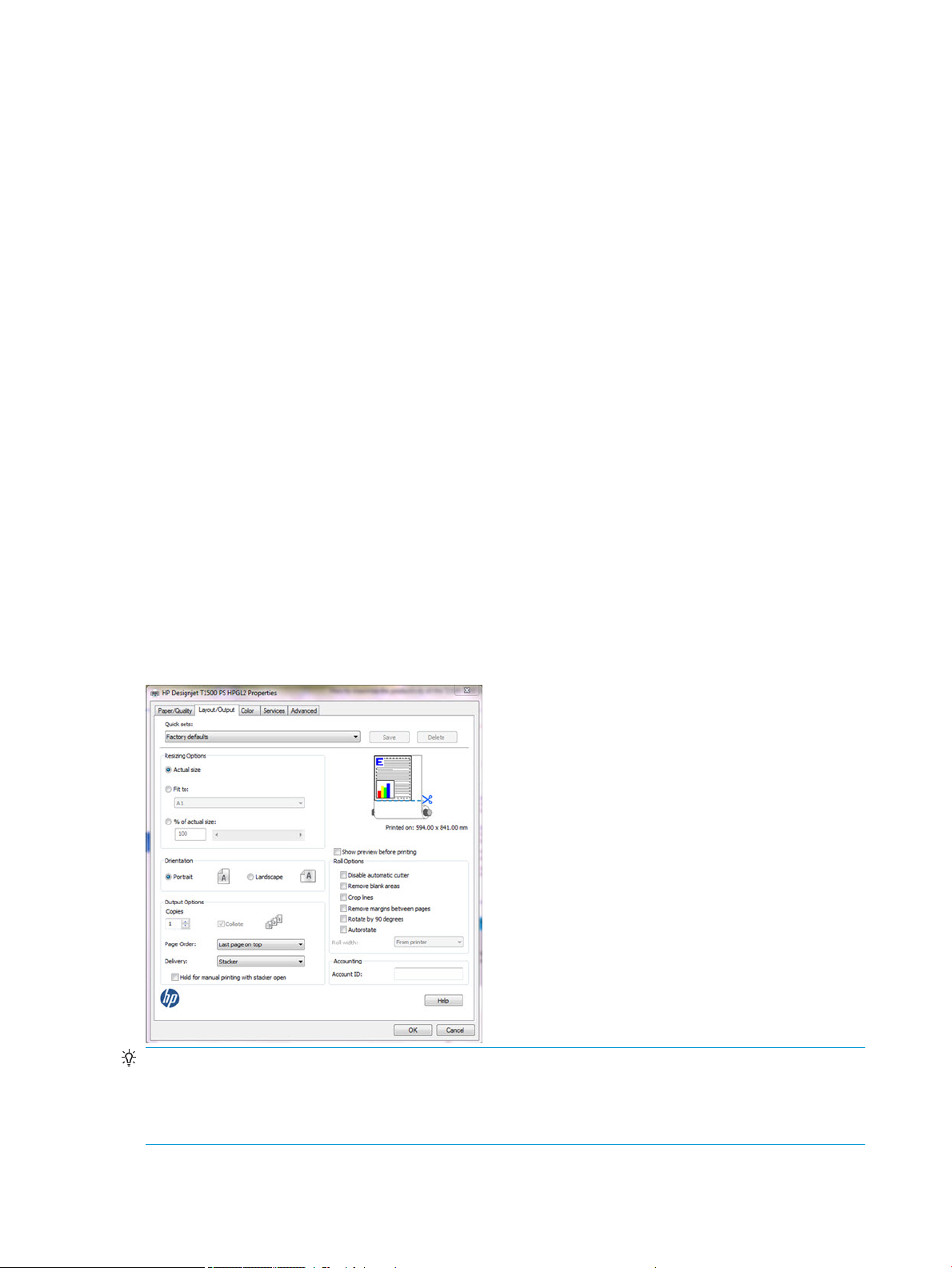
How to switch from stacker to basket and vice versa
The default output is the Stacker, however, switching to the basket is very easy:
In driver properties, select the Layout/Output tab, then in Output options select Basket for Delivery:
TIP: Also use this setting together with the Quick sets in the driver or as a driver default by going to Windows
Start, then Device and printers and editing the Printing properties.
TIP: At any time, the jobs appearing in the queue can be redirected and sent to either the stacker or the basket
by modifying the job setting in the Front Panel.
64 Chapter 2 Troubleshooting ENWW
Page 75

Manual mode
Manual mode is designed to help maximum print quality with photo media. The driver automatically enables
Manual mode when photo media is selected in the driver; the job now waits in queue for the stacker to open, and
to be activated. This ensures the stacker doesn’t touch the print while drying. If jobs are not required to be "Hold
for manual mode" there are 2 options:
1. Manual mode can be enabled/disabled in the Layout/options tab in the driver by clicking in the checkbox
2. Disable the driver check for photo media so Manual mode is not enabled automatically. Press the Start
Hold for manual printing with stacker open.
button, select Devices and Settings, and right-click the printer’s icon. Select Printer Properties. Select
Device Settings.
NOTE: When a job is put "On hold for manual mode" the printer doesn’t stop; while this job is waiting, and if the
stacker is closed, other jobs can still be sent and printed.
NOTE: After printing the job sent in Manual mode with the stacker open, the printer stops until the stacker is
closed, or another job is sent from the queue.
Resuming print interruptions
The stacker has a sensor to prevent unexpected behavior of the media in the tray, and ensure that the jams
never reach the printhead. Eventually, when prompted by the printer, it’s required to go to the stacker and
correct it by attening the paper. Once xed, printing will resume.
Media jam frequency may increase under certain conditions; when printing images with very high ink density on
light media like Bond or Coated under specic environmental conditions such as 30ºC-86ºF/70%. In such cases,
switching to a media with higher grammage such as HP Heavy Weight Coated can help to increase productivity.
The paper type is not in the list
To work with a paper that does not appear in the list in the driver or front panel, you can choose one of the other
papers in the list. However, you should at least choose a paper of the same type: transparent or translucent,
photo or bond, coated or technical.
ENWW Paper handling problems 65
Page 76

NOTE: For photo paper, it is important to select a photo paper type, as the printer adjusts its use of ink for
photo paper.
Transparent or translucent lm
If your paper is a transparent lm (for example, a transparency), select paper type Film > Transparent/Clear lm.
If your paper is a translucent paper or lm (for example, technical paper), select paper type Film > Matte lm.
Photo paper
If your paper is a photo paper, use the Photo Paper category. For gloss or high-gloss paper, select paper type
Photo Gloss Paper. For semi-gloss, satin, pearl, or luster nishes, select paper type Photo Semi-gloss/Satin
Paper.
To increase gamut on photo paper, select paper type HP Universal Gloss Photo Paper or HP Universal Satin
Photo Paper, depending on the nish.
Bond and coated or technical paper
Your paper type selection for generic paper depends on the paper’s ink absorption capacity.
●
For thin papers (< 90 g/m2) or uncoated papers (for example plain paper or bright white paper), select
paper type Bond and Coated Paper > Plain Paper. You can also select Recycled Bond Paper.
●
For light coated papers (< 110 g/m2), select paper type Bond and Coated Paper > HP Coated Paper.
●
For heavyweight coated papers (< 200 g/m2), select paper type Bond and Coated Paper > Heavyweight
Coated Paper.
Black ink is easily removed when touched
This happens when your paper is incompatible with matte black ink. To use an optimized ink combination, select
paper type Photo Paper > Photo Gloss Paper.
After printing, the paper has wrinkles or there is too much ink
Reduce the quantity of ink, or use thicker paper. Matte paper categories from thinnest to thickest are:
●
Plain Paper
●
Coated Paper
●
Heavyweight Coated Paper
●
Super Heavyweight Plus Matte Paper
TIP: If you load paper that is slightly thicker than the paper type you selected, the printer will use less ink than
usual for the loaded paper.
The printer printed on the wrong paper type
If the printer prints your job before you were able to load your desired paper, you may have Any or Use printer
settings selected for the Paper Type in the printer driver. In this case, the printer will print immediately on
whichever paper is loaded. Load your desired paper, and select your paper type specically in the driver.
66 Chapter 2 Troubleshooting ENWW
Page 77

●
In the Windows driver dialog: select the Paper/Quality tab, then select your paper type from the Paper Type
list.
●
In the Mac OS X Print dialog: select the Paper/Quality panel, then select your paper type from the Paper
Type list.
NOTE: The driver default is Any for Mac OS and Use printer settings for Windows; they have the same eect.
An “on hold for paper” message
Based on a set of conditions that you can set when sending a job to a two-roll printer, the printer will decide
which of the loaded rolls of paper is more suitable to print the job. If there is no roll of paper available that meets
all the conditions, the printer will put the job on hold for paper. You can manually resume the job, forcing it to
print on a paper other than the one originally specied, otherwise it will stay on hold.
Which criteria are used to decide on which roll a job will be printed?
When a user sends a job, the desired paper type can be set (in the driver or in the Embedded Web Server). The
printer will print the job on a roll of paper of the chosen paper type that is large enough to print the drawing
without clipping. If there is more than one roll on which the job could be printed meeting all the criteria, the roll
will be chosen according to your preferences. These can be set from the front panel.
When is a job put on hold for paper?
If the paper mismatch action is set to Put job on hold, a job is put on hold for paper in the following cases:
●
The paper type that has been selected by the user is not currently loaded on the specied roll—or on
either of the rolls, if no roll has been specied.
●
The paper type that has been selected by the user is loaded on the specied roll, but the drawing is too
large to t on the roll—or on either of the rolls, if no roll has been specied.
If I load a new roll of paper, will jobs that were on hold for paper be automatically printed?
Yes. Every time a new roll of paper is loaded, the printer will check if there are any jobs on hold for paper that
could be printed on the loaded roll.
I don’t like jobs being put on hold for paper. Can I prevent it?
Yes, this can be done from the front panel.
I set the option “Paper mismatch action” to “Print anyway”, but some jobs are still put on hold
(Windows driver only)
If the Show print preview option is selected in the driver or the Embedded Web Server, jobs are put on hold until
you have checked the preview and resumed the job. Check that the Show print preview option is not checked in
the driver, and that there are no pending preview windows waiting for conrmation to continue printing.
My job is exactly as wide as the roll of paper that is loaded on the printer, but is put on hold for paper
Margins are managed in dierent ways depending on the le type:
ENWW Paper handling problems 67
Page 78

●
For HP-GL/2 and HP RTL les, by default, margins are included inside the drawing, so a 914 mm (36 in) HPGL/2 and HP RTL le can be printed on a 914 mm (36 in) roll of paper and will not be put on hold for paper.
●
For other le formats, such as PostScript, PDF, TIFF or JPEG, the printer assumes that margins need to be
added outside the drawing (as, in many cases, these formats are used for photographs and other images
that do not include margins). This means that, to print a 914 mm (36 in) TIFF, the printer needs to add
margins, and the drawing needs 925 mm (36.4 in) of paper to be printed; this would cause the job to be put
on hold if the paper that is loaded on the printer is only 914 mm (36 in) wide.
If you wish to print these le formats without adding extra margins outside of the drawing, the Clip
contents by margins option can be used. This option will force the margins to be set inside of the drawing,
so a 914 mm (36 in) TIFF can be printed on a 914 mm (36 in) roll of paper without being put on hold.
However, if there is no white space already included in the drawing’s borders, some contents could be
clipped because of the margins.
NOTE: If you choose the option Match exact size, your job will be printed only on paper whose width exactly
matches the width of the job.
The printer displays out of paper when paper is available
If the roll has become loose from its core, it will not feed correctly and the printer will not load the paper. If
possible, tighten the paper to its core or load a new roll.
The print remains in the printer after printing has completed
The printer holds the paper to allow the print to dry after printing. If a sheet of paper is only partially ejected
after the drying time, gently pull it out of the printer.
The cutter does not cut well
By default, the printer is set to cut the paper automatically after each job.
If the cutter is turned on but not cutting correctly, check that the cutter rail is clean and clear of any obstacles.
Even if the cutter is set to O, the printer will still cut while:
●
Switching from Roll 1 to Roll 2 or viceversa
●
Switching the output from Stacker to Basket, and viceversa
If the cutter is not cutting, check that the carriage engages properly with the cutter actuator in order to activate
it.
●
Launch printhead replacement.
●
Power of the printer with the rear power switch when the carriage is in the middle of the printer.
●
At this point, the cutter should be activated.
●
Move the carriage manually to the service station side end to disengage the cutter.
●
Move the carriage manually to the Front panel side end to engage it again.
●
Notice the noise made by the engagement/disengagement, and also that the carriage friction is higher
when the cutter is engaged.
68 Chapter 2 Troubleshooting ENWW
Page 79

●
Finally, move the carriage manually to the service station side end to disengage the cutter.
●
Power on the printer.
Finally, if code SE86:01 appears while cutting, it may be required to manually readjust the Encoder Strip and
move it up slightly.
The roll is loose on the spindle
The roll may need to be replaced or reloaded.
The roll is unloaded unexpectedly
In the cases below an excess of friction is causing a malfunction in the media input which causes the ,edoa roll to
unload unexpectedly.
One of the main causes of friction is that the sides of the paper are brushing against the hubs for dierent
possible reasons, such as:
●
Media has expanded due to climatic conditions (for example, switching o Air Conditioning).
●
Poor quality media with telescoping, core is narrower than media.
Call agent:
1. Ask customer if the issue has happened while printing. If so, refer to 39.11:01 Media unloaded (Advisory)
on page 138 troubleshooting.
2. Upgrade the printer to the latest rmware.
3. Ask customer to open roll cover and feed media into the media path.
a. Check if the sides of the media roll are brushing against the hubs. If they are, tell customer to
reposition the media roll on the spindle ensuring some margin (≈3mm) between the sides of the
media and the black and blue hubs and check that it does not brush against the hubs anymore. If this
is not the case, continue troubleshooting as below.
b. Visually check that the hubs (black and blue pieces) are not broken. If they are damaged, send a new
spindle to the customer.
ENWW Paper handling problems 69
Page 80

Ink supply problems
●
Cannot insert an ink cartridge
●
Ink cartridge status messages
●
Problems during insertion
●
Clean the printhead
●
Align the printhead
●
Printhead status messages
●
Printhead 727 Error codes
Cannot insert an ink cartridge
1. Check that you have the correct type of cartridge (model number).
2. Check that the colored label on the cartridge is the same color as the label on the slot.
3. Check that the cartridge is correctly oriented, with the letter or letters marking the cartridge label right-side
up and readable.
CAUTION: Never clean inside the ink cartridge slots.
Ink cartridge status messages
These are the possible ink cartridge status messages:
●
OK: The cartridge is working normally, with no known problems.
●
Missing: There is no cartridge present, or it is not correctly connected to the printer.
●
Low: The ink level is low.
●
Very low: The ink level is very low.
●
Empty: The cartridge is empty.
●
Reseat: You are recommended to remove the cartridge and then reinsert it.
●
Replace: You are recommended to replace the cartridge with a new cartridge.
●
Expired: It is past the cartridge's expiration date.
●
Incorrect: The cartridge is not compatible with this printer. The message includes a list of compatible
cartridges.
●
Non-HP: The cartridge is used, relled, or counterfeit.
●
Not Valid: If the printer doesn't have enough ink to perform an operation, it will display the front panel
message “Not Valid For Operation”. In order to remove the messag,e a cartridge containing more ink is
needed.
70 Chapter 2 Troubleshooting ENWW
Page 81

Problems during insertion
At installation
NOTE: To better understand the start up process, see HP 727 Printhead Start-up process on page 28.
Prerequisites: Before starting any troubleshooting, do the following:
1. Ensure the latest rmware is installed in the printer. If you need to update the rmware, download the
latest version from www.hp.com/go/T1500/software.
2. Download the Service plot (this helps to check for error codes and ink levels.
3. Make sure there is enough ink to start up the printhead (40cc for matte black (mK) and 30cc for other inks;
for a tubes purge - 60cc for each color). Ink levels can be checked in the service plot. If in doubt, use 130ml
cartridges.
4. Ensure that septum is gently moisturized (see below)
The tube connectors can be lubricated by moistening with water to help with the insertion of the printhead.
This can be done as follows:
a. Moisten a soft cotton bud with Water or PEG.
b. Open the carriage latch completely.
ENWW Ink supply problems 71
Page 82

c. Use the wet cotton bud to moisten the septum.
d. Close latch. If necessary, push against the rear side of the carriage to ensure it is properly closed.
The carriage latch is not closed properly
The carriage appears to be closed, but the blue latch sticks up a little and does not stay at.
How to check:
▲
Ensure that:
a. The carriage latch is properly engaged.
72 Chapter 2 Troubleshooting ENWW
Page 83

b. The latch is completely down.
If these two conditions are not met, printhead installation may fail and/or some tubes may not be lled
with ink.
NOTE: If the carriage is open, it will be detected by the printer and the customer will be asked to try to
close it again. However, if the carriage is not closed and the printer is powered o, there is a risk that, after
booting up, the printer will raise service system error 86:01. In this case, turn the printer o again, close the
carriage (removing the printhead, if necessary), and then move the printhead to the Service Station. Finally
boot up the printer again.
Root Cause
Incorrect printhead insertion can cause errors because of insucient lubrication or the latch not engaging
properly.
Corrective actions:
1. Perform Prerequisites (Firmware upgrade, moisturize septums).
2. Check that you have the correct type of printhead (model number).
3. Check that the printhead is correctly oriented.
4. Check that you have correctly closed and latched the printhead cover.
ENWW Ink supply problems 73
Page 84

The front panel display recommends reseating the printhead after insertion and no tubes start to ll (tubes are empty)
The printer brings the printhead to the Service Station and rejects it immediately.
1. Perform Prerequisites (Firmware upgrade, moisturize septums).
2. Send/Bring a set of ink supplies plus PHA.
3. Check Printhead errors:
How to check:
When a reseat message appears, the printer will show a printhead error on the Front Panel.
The printer has not yet started to pump ink into the tubes.
Check the Printhead error code
●
On the Front Panel check the Printhead “status”:
Go to Main Menu — Printhead — Printhead information.
●
From EWS:
Generate the Service plot. Go to the Embedded Web Server: Support tab -> Service support -> Printer
information. This will open a new page. Select the All pages tab. Download this page or print it to a
PDF le.
Printhead error related to RESEAT:
Status
code
(dec)
0 0x0 WORKING OK The pen is working
2 0x2 FAILS_CONTINUITY RESEAT Pen ID
4 0x4 SHUTDOWN – Not used NA Trailing cable/
32 0x20 TEMP_EXTREMELY_LO
Status
code
(hex) Status name
W
User reported
status
RESEAT The temperature
Description on
printer HW Test Troubleshooting
properly
of the pen is below
the normal
margins
All -
programming
and pen
continuity
Thermal
runtime tests
Trailing cable/
PSU/ E-box
PSU/ E-box
PHA Replace
74 Chapter 2 Troubleshooting ENWW
Page 85

Status
code
(dec)
Status
code
(hex) Status name
User reported
status
Description on
printer HW Test Troubleshooting
128 0x80 TEMP_TOO_LOW RESEAT The temperature
of the pen is below
the normal
margins
8192 0x2000 CSDATA_NOT_RESPON
DING
16384 0x4000 CSDATA_TRANSMIT_ER
ROR
RESEAT The CSDATA
communication
fails
RESEAT The CSDATA
communication is
erroneous
4. If the printhead shows Reseat error code (0x00002, 0x02000, 0x04000...)
Root Cause
●
If the printer rejects the printhead before even trying to initiate tube purging, it can indicate that the
printer does not recognize the printhead. This may also cause a 0x00002 printhead Error Code to be
shown on the Front Panel.
●
The printer is not able to communicate with the printhead.
●
Other issues.
Corrective action
●
Reseat the same printhead and try again. Follow Front Panel instructions. Do not stop the servicing
routines, allow the printhead to be initialized.
Thermal
runtime tests
Pen ID
programming
Every pen
communication
PHA Replace
Trailing/PHA
Trailing/PHA
●
If it fails replace it with a new PHA and follow Front Panel instructions.
●
Try 2 times more with the new PHA.
●
If the reseat message continues to appear, check the carriage PCA using the Carriage test in the
diagnostic menu. Replace carriage PCA if needed.
5. If there is no Printhead error shown on the Front Panel or EWS
Root Cause
●
Unknown.
Corrective action
●
Reseat the same printhead and try again. Follow Front Panel instructions.
After this process it may end on a PH reseat with a PHA error (see step 4 inCheck the Printhead error
code on page 74) or in a Printhead replacement (see The front panel display shows “PH replacement
not complete” on page 75).
The front panel display shows “PH replacement not complete”
The printhead is rejected and some ink tubes are not lled: Yellow and Matte Black are missing, or Cyan,
Magenta, Gray, and Photo Black are missing.
1. Perform Prerequisites (Firmware upgrade, moisturize septums).
ENWW Ink supply problems 75
Page 86

2. For Printers prior to May 2014 (for T3500 go to 3.3).
Visually check if there are empty tubes:
a. Open the carriage.
b. Check the end of the tubes. They should appear as shown in the picture below. The rest of the ink
circuit can be checked for bubbles and ink. When the tubes are empty, they will have a bluish color.
When lled, the tubes will look darker and the yellow channel will have a slight magenta color (due to
the combination of ink color and tube color).
Filled tubes:
Empty tubes:
Root Cause
–
There are two primer channels. Yellow and Matte Black share one primer channel. Cyan,
Magenta, Gray, and Photo Black share the other primer channel. If one primer fails, one of the
groups might not get lled.
–
There are 2 Ink Supply Stations, If the missing colors are grouped as they are in the Ink Supply
Station, this issue can be related to that part of the printer.
Corrective action
–
Run the primer test to check if the primer is working. If it fails, replace the primer.
–
Run the “Ink Delivery System diagnostic” to check the status of the Ink Supply Station . If it fails,
replace the corresponding ISS.
–
Also, ensure that the ink tube connectors are properly lubricated.
76 Chapter 2 Troubleshooting ENWW
Page 87

–
Run a tube purge to ll all the tubes, including the missing color.
–
To purge the tubes, rst remove all supplies (ink and printhead). Then run “Purge tubes” from
the service utilities. Re-insert the inks and printhead, as requested.
NOTE: If a cartridge is inserted and the ink tube is not lled, the printer can potentially mark the
cartridge as “Out Of Ink”. To prevent this from happening, do not install cartridges when some tubes
are empty.
3. For Printers after May 2014 (rmware MRY_02_00_05.6 and later)
In then rmware of those printers, new error codes have been included to simplify diagnosticability of PHA
replacement root cause: Filling SE codes (looking at those SE in the service plot avoids the need to visually
check the ink tubes).
a. Generate the Service plot since the SE93.x.n:10 are not show in the front panel. Go to the Embedded
Web Server: Support tab -> Service support -> Printer information. This will open a new page. Select
the All pages tab. Download this page or print it to a PDF le.
SE 93.0.n:10 During the tube lling, the rst check of ink pressure for color n failed. If no SE 93.2.n:10
appears, it means that the issue was xed after the customer reseated the printhead.
SE 93.2.n:10 After reseating the printhead, the second check of ink pressure for color n failed. This
means that color n in the printhead may not be lled with ink or that the ink tube is leaking.
SE 93.1.n:10 During the tube lling, the rst check of temperature for color n during the printhead
spit test failed. If no SE 93.3.n:10 appears, it means that the issue was xed after the customer
reseated the printhead.
SE 93.3.n:10 During the tube lling and after reseating the printhead, the second check of
temperature for color n during the printhead spit test failed. This means that color n in the printhead
is not lled with ink.
n indicates the color at fault:
–
n=0 stands for photo black
–
n=1 stands for gray
–
n=2 stands for matte black
–
n=3 stands for cyan
–
n=4 stands for magenta
–
n=5 stands for yellow.
b. Service plot shows the following SE:
–
SE 93.1.0:10
–
SE 93.1.1:10
–
SE 93.1.3:10
–
SE 93.1.4:10
–
SE 93.3.0:10
–
SE 93.3.1:10
ENWW Ink supply problems 77
Page 88

–
SE 93.3.3:10
–
SE 93.3.4:10
Root Cause
–
Upper primer than manages 4 ink tubes( Cyan/Magenta/Gray/Photo black)is failing, therefore,
those tubes are not completely lled.
Corrective action
–
Replace upper primer.
–
Run the “Ink Delivery System diagnostic” to check the status of the Ink Supply Station . If it fails,
replace the corresponding ISS.
–
Also, ensure that the ink tube connectors are properly lubricated.
–
Run a tube purge to ll all the tubes, including the missing color.
–
To purge the tubes, rst remove all supplies (ink and printhead). Then run “Purge tubes” from
the service utilities. Re-insert the inks and printhead, as requested.
c. Service plot shows the following SE:
–
SE 93.1.2:10
–
SE 93.1.5:10
–
SE 93.3.2:10
–
SE 93.3.5:10
Root Cause
–
Lower primer than manages 2 ink tubes (Yellow and Matte Black) is failing, therefore, those
tubes are not completely lled.
Corrective action
–
Replace lower primer.
–
Run the “Ink Delivery System diagnostic” to check the status of the Ink Supply Station . If it fails,
replace the corresponding ISS.
–
Also, ensure that the ink tube connectors are properly lubricated.
–
Run a tube purge to ll all the tubes.
–
To purge the tubes, rst remove all supplies (ink and printhead). Then run “Purge tubes” from
the service utilities. Re-insert the inks and printhead, as requested.
d. Service plot shows the following SE:
–
SE 93.1.0:10
–
SE 93.1.1:10
–
SE 93.1.2:10
–
SE 93.3.0:10
78 Chapter 2 Troubleshooting ENWW
Page 89

–
SE 93.3.1:10
–
SE 93.3.2:10
Root Cause
–
Service Station Side Ink Supply Station than manages 3 ink tubes (Gray/Photo black /Matte
black) is failing, therefore, those tubes are not completely lled.
Corrective action
–
Replace Service Station Side Ink supply Station
–
Also, ensure that the ink tube connectors are properly lubricated.
–
Run a tube purge to ll all the tubes.
To purge the tubes, rst remove all supplies (ink and printhead). Then run “Purge tubes” from
the service utilities. Re-insert the inks and printhead, as requested.
e. Service plot shows the following SE:
–
SE 93.1.3:10
–
SE 93.1.4:10
–
SE 93.1.5:10
–
SE 93.3.3:10
–
SE 93.3.4:10
–
SE 93.3.5:10
Root Cause
–
Front Panel Side Ink Supply Station than manages 3 ink tubes(Cyan/Magenta/Yellow)is failing,
therefore, those tubes are not completely lled.
Corrective action
–
Replace Front Panel Side Ink supply Station
–
Also, ensure that the ink tube connectors are properly lubricated.
–
Run a tube purge to ll all the tubes.
To purge the tubes, rst remove all supplies (ink and printhead). Then run “Purge tubes” from
the service utilities. Re-insert the inks and printhead, as requested.
f. Service plot shows one or several 93.x.n:10 SE:
–
If multiple colors are missing, there will be both a SE 93.1.n:10 and SE 93.3.n:10 for each
missing color.
–
If only a SE 93.1.n:10 appears, it means that the color failed to be lled during the rst attempt,
but the printer auto recovery was able to fully ll the printhead.
Root Cause
–
Any of the aforementioned root causes may apply.
ENWW Ink supply problems 79
Page 90

Corrective action
–
Test the primer and Ink Supply Station. Ensure the ink tube connectors are properly lubricated.
–
Run a tube purge to ll all the tubes.
To purge the tubes, rst remove all supplies (ink and printhead). Then run “Purge tubes” from
the service utilities. Re-insert the inks and printhead, as requested.
NOTE: If a cartridge is inserted and the ink tube is not lled, the printer can potentially mark the cartridge
as “Out Of Ink”. To prevent this from happening, do not install cartridges when some tubes are empty.
The printer rebooted during the start-up; printhead initialization took a long time and was then canceled
Root cause
●
Printhead issue.
●
Incorrect error message from drop detection that causes the printer to carry out additional servicing
routines.
●
Other issues.
Corrective action
●
Do not stop the servicing routines, allow the printhead to be initialized.
●
If, after the start-up, the image quality is poor, carry out the usual image quality troubleshooting.
●
If at the moment of interruption (System Error or user intervention) the tubes were already lled, try to reinstall the printhead.
●
If at the moment of interruption (System Error or user intervention) the tubes weren’t fully loaded yet, try
to launch a Tube Purge from the Service Menu.
During Usage
During normal usage, any Printhead reseat or replacement should imply sending a new PHA.
The printhead shows an Error Code 0x00010 or 0x00040
The printhead shows an Error Code 0x00010 or 0x00040.
Root Cause
The nozzle area is overheating. This can be due to air present in the nozzle area of the printhead.
Corrective action
Check that the ink tubes are lled and have no air bubbles. Run manual printhead cleaning to try to restore
the printhead. Ultimately, replace the printhead if needed.
All ink tubes are lled, but the printer requests a random printhead reseat
Root Cause
To analyze the root cause, check the printhead Error Code in the table at the end of this document.
Corrective action
80 Chapter 2 Troubleshooting ENWW
Page 91

The printhead reseat issue can be solved by simply removing and reinstalling the printhead. If, after the
reseat, the error message continues, try a new printhead. If the reseat message continues to appear, check
the carriage PCA using the Carriage test in the diagnostic menu.
During printer installation troubleshooting, the printer asks if the printhead to be used is “New” or “Reused”
Root Cause
Depending on the situation, when trying to replace the printhead with a new one, the printer can ask if the
printhead that is going to be used is “New” or “Reused”. For instance, this can happen when the ink tubes
are lled, but the printhead installation fails during the servicing routines.
Corrective action
If doing a reseat of the old printhead, the “Reused” option should be selected. The “New” option should
only be selected if the printhead that is going to be used needs to be lled with ink. When “New” is
selected, the printer will check if there is enough ink to run the new printhead installation. If there is not
enough ink, the printer will only carry out the servicing routines to prepare the printhead.
Clean the printhead
As long as the printer is kept turned on, automatic cleaning is performed periodically. This ensures there is fresh
ink in the nozzles and prevents nozzle clogs, thus preserving print quality. If you have print quality problems,
please see Print-quality problems on page 84 before proceeding.
To clean the printhead, go to the front panel and press , then , then Image Quality Maintenance >
Clean printhead, and select the color group including the color that needs cleaning (Clean all, Clean MK-Y, Clean
C-M-PK-G).
Align the printhead
Precise printhead alignment is essential for accurate colors, smooth color transitions, and sharp edges in
graphical elements. Your printer has an automatic printhead alignment process which runs whenever the
printhead has been accessed or replaced.
You may need to align the printhead after a paper jam or if you are experiencing print-quality problems.
1. Load the paper you wish to use. You can use a roll or a cut sheet; plain white paper is recommended.
CAUTION: Do not use transparent or semi-transparent paper to align the printhead.
2. Ensure that the window is closed, as a strong light source near the printer during printhead realignment
can aect alignment.
3.
From the front panel, press , then Image Quality Maintenance > Align printhead.
NOTE: Printhead alignment can also be started from the Embedded Web Server (Support > Print Quality
Troubleshooting), or from the HP Utility (Windows: Support > Print Quality Troubleshooting; Mac OS X:
Information and Print Quality > Align).
4. If the loaded paper is satisfactory, the printer runs the realignment and prints a realignment pattern.
5. The process takes about ve minutes. Wait until the front panel display shows the process complete before
using the printer.
ENWW Ink supply problems 81
Page 92

If the printer cannot complete the printhead alignment successfully, you may be asked to clean the printhead
and try again.
Printhead status messages
These are the possible printhead status messages:
●
OK: The printhead is working normally, with no known problems
●
Missing: There is no printhead present, or it is not correctly installed in the printer.
●
Reseat: You are recommended to remove the printhead and then reinsert it. If that fails, clean the electrical
connections. If that fails, replace the printhead with a new one.
●
Replace: The printhead is failing. Replace the printhead with a working one.
●
Replacement incomplete: The printhead replacement process has not completed successfully; re-launch
the replacement process and let it nish completely.
●
Remove: The printhead is not a suitable type for use in printing.
●
Non-HP ink: Ink from a used, relled, or counterfeit ink cartridge has passed through the printhead. See the
limited warranty document provided with your printer for details of the warranty implications.
Printhead 727 Error codes
How to check the printhead error code:
●
Generate the Service plot. Go to the Embedded Web Server: Support tab > Service support > Printer
information. This will open a new page. Select the All pages tab. Download this page or print it to a PDF le.
●
Alternatively, check the printhead “Status” in the Front Panel.
Printhead 727 error codes:
The following table lists the potential error codes reported by the printer:
82 Chapter 2 Troubleshooting ENWW
Page 93

Service
Support /
Printer
Status / Failure
mode
WORKING OK 0 0x00000 The pen is working properly
FAILS_LOGICAL_V RESEAT 1 0x00001 Under-voltage, over-voltage or ink shortage detected in Vcc (5V)
FAILS_CONTINUITYRESEAT 2 0x00002 Failed pen ID programming or pen continuity tests
SHUTDOWN REPLACE 4 0x00004 CsData fault, printhead clock or temperature error
FAILS_VPP RESEAT 8 0x00008 Under-voltage, over-voltage, leakage or ink shortage detected in Vpp or
Action
reported to
user
Information
Code by
EWS
Printhead
Information
by Control
Panel Description
VppLogic
TEMP_EXTREMELY
_HIGH
TEMP_EXTREMELY
_LOW
TEMP_TOO_HIGH RESEAT 64 0x00040 The temperature of the pen has been above the normal margins for too
TEMP_TOO_LOW RESEAT 128 0x00080 The temperature of the pen has been below the normal margins for too
BAD_ACUMEN_INFOREPLACE 256 0x00100 Parity error on printhead bits
NO_PEN MISSING 512 0x00200 There is no pen detected
BAD_ACUMEN_AC
CESS
WRONG_MODEL REMOVE 2048 0x00800 The model inserted is not the model required by the printer
MISMATCH REMOVE 4096 0x01000 The color or the printhead version is not in the required slot
CSDATA_NOT_RES
PONDING
CSDATA_TRANSMI
T_ERROR
EXPIRED_WARRA
NTY
REPLACE 16 0x00010 The temperature of the pen is beyond maximum margin
REPLACE 32 0x00020 The temperature of the pen is under minimum margin
long
long
RESEAT 1024 0x00400 Error while reading or writing printhead bits
RESEAT 8192 0x02000 The CSDATA communication failed
RESEAT 16384 0x04000 The CSDATA communication failed
— 524288 0x80000 The printhead is ok but failed the warranty validation
ENWW Ink supply problems 83
Page 94

Print-quality problems
●
General advice
●
Print-quality troubleshooting wizard
●
Recalibrate the paper advance
●
Horizontal lines across the image (banding)
●
Lines are too thick, too thin or missing
●
Lines appear stepped or jagged
●
Lines print double or in the wrong colors
●
Lines are discontinuous
●
Lines are blurred
●
Line lengths are inaccurate
●
The whole image is blurry or grainy
●
The paper is not at
●
The print is scued or scratched
●
Ink marks on the paper
●
Black ink comes o when you touch the print
●
Edges of objects are stepped or not sharp
●
Edges of objects are darker than expected
●
Horizontal lines at the end of a cut sheet print
●
Vertical bands of dierent colors
●
White spots on the print
●
Colors are inaccurate
●
Colors are fading
●
The image is incomplete (clipped at the bottom)
●
The image is clipped
●
Some objects are missing from the printed image
●
A PDF le is clipped or objects are missing
●
Avoiding the stretching of printouts in Solidworks and HPGL2 drivers
●
The Image Diagnostics Print
●
Product Limitations
●
If you still have a problem
84 Chapter 2 Troubleshooting ENWW
Page 95

General advice
When you have any print-quality problem:
●
To achieve the best performance from your printer, use only genuine manufacturer's supplies and
accessories, whose reliability and performance have been thoroughly tested to give trouble-free
performance and best-quality prints. For details of recommended papers, see users guide.
●
Make sure that the paper type selected in the front panel is the same as the paper type loaded into the
printer (see users guide). At the same time, check that the paper type has been calibrated. Also make sure
that the paper type selected in your software is the same as the paper type loaded into the printer.
CAUTION: If you have the wrong paper type selected, you could experience poor print quality and
incorrect colors, and perhaps even damage to the printhead.
●
Check that you are using the most appropriate print-quality settings for your purposes (see users guide).
You are likely to see lower print quality if you have moved the print-quality slider to the 'Speed' end of the
scale, or set the custom quality level to Fast.
●
Check that your environmental conditions (temperature, humidity) are in the recommended range. See
users guide.
●
Check that your ink cartridges and printhead have not passed their expiration dates: see users guide.
For the latest information, please visit http://www.hp.com/go/T920/support or http://www.hp.com/go/T1500/
support.
Print-quality troubleshooting wizard
The print-quality troubleshooting wizard can help with the following problems:
●
Horizontal lines across the image (banding)
●
The whole image is blurry or grainy
●
Lines are too thick, too thin or missing
●
Colors are inaccurate
To start the wizard:
●
From the HP Designjet Utility for Windows: Go to the Support tab, and select Print Quality Toolbox.
●
From the HP Utility for Mac OS X: Select Print quality troubleshooting in the Support group.
●
From the Embedded Web Server: Go to the Support tab, then select Print quality troubleshooting.
●
From the front panel: Press , then , then Image quality maintenance.
Alternatively, or if you have other print-quality problems, you can continue reading this chapter.
Recalibrate the paper advance
Accurate paper advance is important to image quality because it is part of controlling the proper placement of
dots on the paper. If the paper is not advanced the proper distance between printhead passes, light or dark
bands appear in the print and image grain may increase.
ENWW Print-quality problems 85
Page 96

The printer is calibrated to advance correctly with all the papers appearing in the front panel. When you select
the type of loaded paper, the printer adjusts the rate at which to advance the paper while printing. However, if
you are not satised with the default calibration of your paper, you may need to recalibrate the rate at which the
paper advances. See users guide for steps to determine if paper advance calibration will solve your issue.
You can check the paper advance calibration status of the currently loaded paper at any time from the front
panel. Press , then , then Image quality maintenance > Calibration status. The status may be one of
the following.
●
DEFAULT: This status appears when loading any paper that has not been calibrated. HP papers in the Front
Panel have been optimized by default and unless you experience image quality problems in your printed
image such as banding or graininess it is not recommended to recalibrate the paper advance.
●
OK: This status indicates that the loaded paper has been calibrated before. However you may need to
repeat the calibration if you experience image quality problems such as banding or graininess in your
printed image.
NOTE: Whenever you update the printer’s rmware, the paper advance calibration values are reset to
factory default, see users guide.
CAUTION: Transparent papers and lms must be calibrated by pressing , then , then Image quality
maintenance > Paper advance calibration > Adjust paper advance, from step four in Recalibrating the paper
advance procedure.
Recalibrating the paper advance procedure
1.
From the front panel, press , then , then Image quality maintenance > Paper advance
calibration > Calibrate paper advance. The printer automatically recalibrates the paper advance and prints a
paper advance calibration image, which you can send to stacker or basket.
2. Wait until the front panel displays the status screen, then reprint your print.
NOTE: The recalibration procedure takes a few minutes. Do not worry about the paper advance
calibration image. The front-panel display shows any errors in the process.
If you are satised with your print continue using this calibration for your paper type. If you see
improvement in your print, continue with step three. If you are dissatised with the recalibration, return to
the default calibration, see Return to default calibration on page 87.
3.
If you would like to ne-tune the calibration or are using a transparent paper, press , then ,
then Image quality maintenance > Paper advance calibration > Adjust paper advance.
86 Chapter 2 Troubleshooting ENWW
Page 97

4. Select the percentage of change from –100% to +100%. To correct light banding, decrease the percentage.
To correct dark banding, increase the percentage.
5. Press OK on the front panel, to save the value.
6. Wait until the front panel displays the status screen and reprint your print.
Return to default calibration
Returning to the default calibration sets all the corrections made by the paper advance calibration to zero. To
return to the default paper advance calibration value, you must reset the calibration.
1.
From the front panel, press , then , then Image quality maintenance > Paper advance
calibration > Reset paper advance.
2. Wait until the front panel displays the operation has completed successfully.
Horizontal lines across the image (banding)
If your printed image suers from added horizontal lines as shown (the color may vary):
ENWW Print-quality problems 87
Page 98

1. Check that the paper type you have loaded corresponds to the paper type selected in the front panel and in
your software. See users guide.
2. Check that you are using appropriate print-quality settings for your purposes (see users guide). In some
cases, you can overcome a print-quality problem merely by selecting a higher print-quality level. For
instance, if you have set the Print Quality slider to Speed, try setting it to Quality. If you change the printquality settings, you may wish to reprint your job at this point in case the problem has been solved.
3. Print the Image Diagnostics Print. See The Image Diagnostics Print on page 98.
4.
If the printhead is working correctly, go to the front panel and press , then , then Image quality
maintenance > Calibration status to see the paper advance calibration status. If the status is DEFAULT, try
performing paper advance calibration: see Recalibrate the paper advance on page 85.
In case you are using rolls with 3-in core adaptors:
1. Check that the roll core is not damaged.
2. Make sure that the 3-in adaptor is correctly attached to the spindle.
3. Print using Roll 1 for better performance.
4. Print in a higher quality/slower mode.
5. If horizontal banding is only showing in the laterals of the media, check that the 3-in. adaptors are
positioned so that the spring of the black hub and the blue hub are aligned:
If the problem persists despite all the above actions, contact your customer service representative for further
support.
88 Chapter 2 Troubleshooting ENWW
Page 99

Lines are too thick, too thin or missing
1. Check that the paper type you have loaded corresponds to the paper type selected in the front panel and in
your software. See users guide.
2. Check that you are using appropriate print-quality settings for your purposes (see users guide). If printing
on photo paper, select the custom print-quality options in the driver dialog, and try turning on the
Maximum detail option (if available). You may wish to reprint your job at this point in case the problem has
been solved.
3. If the resolution of your image is greater than the printing resolution, you may notice a loss of line quality. If
you are using the PCL3GUI or the HP-GL/2 driver for Windows, you can nd the Max. Application Resolution
option in the driver dialog's Advanced tab, under Document Options > Printer Features. If you change this
option, you may wish to reprint your job at this point in case the problem has been solved.
4. When printing on uncoated paper in Fast mode, try loading the paper as Bright Bond.
5.
If the problem remains, go to the front panel and press , then , then Image quality
maintenance > Align printhead to see the printhead alignment status. If the status is PENDING, you should
align the printhead. See Align the printhead on page 81. After alignment, you may wish to reprint your job
in case the problem has been solved.
6.
Go to the front panel and press , then , then Image quality maintenance > Calibration status to
see the paper advance calibration status. If the status is DEFAULT, you should perform paper advance
calibration: see Recalibrate the paper advance on page 85.
7. If lines are too thin or missing, print the Image Diagnostics Print. See The Image Diagnostics Print
on page 98.
If the problem persists despite all the above actions, contact your customer service representative for further
support.
Lines appear stepped or jagged
If lines in your image appear stepped or jagged when printed:
ENWW Print-quality problems 89
Page 100

1. The problem may be inherent in the image. Try to improve the image with the application you are using to
edit it.
2. Check that you are using appropriate print-quality settings. See users guide.
3. Select the custom print-quality options in the driver dialog, and turn on the Maximum detail option (if
available).
Lines print double or in the wrong colors
This problem can have various visible symptoms:
●
Colored lines are printed double, in dierent colors.
●
The borders of colored blocks are wrongly colored.
To correct this kind of problem:
1. Align the printhead. See Align the printhead on page 81.
2. Reseat the printhead by removing and then reinserting it. See users guide.
Lines are discontinuous
If your lines are broken in the following way:
1. Check that you are using appropriate print-quality settings. See users guide.
2. When printing on uncoated paper in Fast mode, try loading the paper as Bright Bond.
90 Chapter 2 Troubleshooting ENWW
 Loading...