


 Loading...
HP Color LaserJet Pro M252, Color LaserJet Pro M274, Color LaserJet Pro M277 Troubleshooting manual and Repair manual
ColorLaserJet Pro M252
ColorLaserJet Pro MFP M274
ColorLaserJet Pro MFP M277
Troubleshooting manual
M274 |
M252n |
M252dw |
M277 |
|
|
www.hp.com/support/colorljM252
www.hp.com/support/colorljM274MFP
www.hp.com/support/colorljMFPM277
For printer part removal and part number information, see the Repair Manual

HP Color LaserJet Pro M252, HP Color LaserJet Pro MFP M274 and M277
Troubleshooting Manual
Copyright and License
© Copyright 2015 HP Development Company,
L.P.
Reproduction, adaptation, or translation without prior written permission is prohibited, except as allowed under the copyright laws.
The information contained herein is subject to change without notice.
The only warranties for HP products and services are set forth in the express warranty statements accompanying such products and services. Nothing herein should be construed as constituting an additional warranty. HP shall not be liable for technical or editorial errors or omissions contained herein.
Edition 2, 10/2015

Conventions used in this guide
TIP: Helpful hints or shortcuts.
Reinstallation tip: Reinstallation helpful hints, shortcuts, or considerations.
 NOTE: Information that explains a concept or how to complete a task.
 IMPORTANT: Information that help the user to avoid potential printer error conditions.
 CAUTION: Procedures that the user must follow to avoid losing data or damaging the printer.
 WARNING! Procedures that the user must follow to avoid personal injury, catastrophic loss of data, or extensive damage to the printer.
ENWW |
iii |
iv |
Conventions used in this guide |
ENWW |

For additional service and support information
HP service personnel, go to the Service Access Work Bench (SAW) at http://h41302.www4.hp.com/km/saw/ home.do.
Channel partners, go to HP Channel Services Network (CNS) at https://h30125.www3.hp.com/hpcsn.
●To access HP PartSurfer information from any mobile device, go to http://partsurfermobile.hp.com/ or scan the Quick Response (QR) code below.
●Install and con gure
●Printer speci cations
●Up-to-date control panel message (CPMD) troubleshooting
●Solutions for printer issues and emerging issues
●Remove and replace part instructions and videos
●Service advisories
●Warranty and regulatory information
ENWW |
v |
vi |
For additional service and support information |
ENWW |

Table of contents
1 Theory of operation ....................................................................................................................................... |
1 |
Related documentation and software ................................................................................................................... |
2 |
Basic operation ...................................................................................................................................................... |
3 |
Sequence of operation ........................................................................................................................ |
4 |
Formatter-control system ..................................................................................................................................... |
5 |
Sleep delay .......................................................................................................................................... |
5 |
Printer job language (PJL) ................................................................................................................... |
5 |
Printer management language (PML) ................................................................................................. |
6 |
Control panel ....................................................................................................................................... |
6 |
Walk-up USB (touchscreen models only) ............................................................................................ |
6 |
Wireless (wireless models only) .......................................................................................................... |
6 |
Low end data model (LEDM) ................................................................................................................ |
6 |
Advanced control language (ACL) overview ........................................................................................ |
6 |
Near eld communication (NFC) (wireless models only) .................................................................... |
7 |
CPU ....................................................................................................................................................... |
7 |
Input/output ........................................................................................................................................ |
7 |
USB .................................................................................................................................... |
7 |
USB hosts .......................................................................................................................... |
7 |
10/100 networking ........................................................................................................... |
7 |
Fax (M277 models only) .................................................................................................... |
7 |
Memory ................................................................................................................................................ |
7 |
Firmware ........................................................................................................................... |
7 |
Nonvolatile random access memory (NVRAM) ................................................................. |
7 |
Flash memory ................................................................................................................... |
7 |
Random access memory (RAM) ........................................................................................ |
8 |
HP Memory enhancement technology (MEt) .................................................................... |
8 |
Engine-control system .......................................................................................................................................... |
9 |
Engine control unit (ECU) .................................................................................................................. |
10 |
DC controller ................................................................................................................... |
10 |
High-voltage power supply ............................................................................................ |
11 |
Motors ............................................................................................................................. |
11 |
Fans ................................................................................................................................. |
12 |
ENWW |
vii |
Solenoids ......................................................................................................................... |
12 |
Switches .......................................................................................................................... |
13 |
Sensors ........................................................................................................................... |
14 |
Low-voltage power supply ................................................................................................................ |
15 |
Overcurrent/overvoltage protection .............................................................................. |
15 |
Low-voltage power supply unit failure detection .......................................................... |
15 |
Engine laser scanner system ............................................................................................................................... |
16 |
Laser failure detection ...................................................................................................................... |
16 |
Image formation system ..................................................................................................................................... |
17 |
Image formation process .................................................................................................................. |
17 |
Step 1: Primary charging ................................................................................................ |
17 |
Step 2: Laser-beam exposure ......................................................................................... |
19 |
Step 3: Development ...................................................................................................... |
19 |
Step 4: Primary transfer ................................................................................................. |
20 |
Step 5: Secondary transfer ............................................................................................. |
20 |
Step 6: Separation ........................................................................................................... |
21 |
Step 7: Fusing .................................................................................................................. |
21 |
Step 8: Drum cleaning ..................................................................................................... |
21 |
Toner cartridges ................................................................................................................................ |
23 |
Design ............................................................................................................................. |
23 |
Memory chip .................................................................................................................... |
24 |
HP Cartridges with JetIntelligence ................................................................................. |
24 |
HP Cartridge Policy ....................................................................................... |
24 |
Anti-theft or cartridge protection ................................................................ |
24 |
Intermediate transfer belt (ITB) assembly ........................................................................................ |
24 |
Engine pickup, feed, and delivery system ........................................................................................................... |
26 |
Priority input slot pickup ................................................................................................................... |
29 |
Cassette pickup ................................................................................................................................. |
30 |
Duplexing unit ................................................................................................................................... |
30 |
Duplex reverse and duplex feed control ........................................................................ |
31 |
Duplex pickup operation ................................................................................................. |
31 |
Jam detection .................................................................................................................................... |
32 |
Scanning and image capture system .................................................................................................................. |
33 |
Automatic document feeder (ADF) system ......................................................................................................... |
34 |
ADF simplex operation ...................................................................................................................... |
34 |
Fax functions and operation (fax models only) .................................................................................................. |
35 |
Computer and network security features ......................................................................................... |
35 |
PSTN operation .................................................................................................................................. |
35 |
Receive faxes when you hear fax tones ............................................................................................ |
35 |
Distinctive ring function .................................................................................................................... |
36 |
Set up the distinctive ring function ................................................................................ |
36 |
viii |
ENWW |
Fax by using voice over IP (VOIP) services ........................................................................................ |
36 |
The fax subsystem ............................................................................................................................ |
37 |
Fax card in the fax subsystem ........................................................................................................... |
37 |
Safety isolation ............................................................................................................... |
37 |
Safety-protection circuitry ............................................................................................. |
37 |
Data path ......................................................................................................................... |
37 |
Hook state ....................................................................................................................... |
38 |
Downstream device detection ........................................................................................ |
38 |
Hook switch control ........................................................................................................ |
38 |
Ring detect ...................................................................................................................... |
38 |
Line current control ......................................................................................................... |
38 |
Billing or metering tone lters ....................................................................................... |
39 |
Fax page storage in flash memory .................................................................................................... |
39 |
Stored fax pages ............................................................................................................. |
39 |
Advantages of flash memory storage ............................................................................ |
39 |
2 Solve problems ............................................................................................................................................ |
41 |
Troubleshooting process ..................................................................................................................................... |
42 |
Solve problems checklist ................................................................................................................... |
42 |
Print the menu map ........................................................................................................ |
43 |
Print a con guration page .............................................................................................. |
43 |
Print the service page (includes the event log) .............................................................. |
44 |
Determine the problem source ......................................................................................................... |
44 |
Troubleshooting flowchart ............................................................................................. |
44 |
Power subsystem .............................................................................................................................. |
45 |
Power-on checks ............................................................................................................. |
45 |
Power-on troubleshooting overview ........................................................... |
45 |
Control panel checks ......................................................................................................................... |
49 |
Tools for troubleshooting .................................................................................................................................... |
50 |
Individual component diagnostics .................................................................................................... |
50 |
Tools for troubleshooting: LED diagnostics ................................................................... |
50 |
Network port LEDs ....................................................................................... |
50 |
Two-line control panel LEDs ........................................................................ |
51 |
Tools for troubleshooting: Engine diagnostics .............................................................. |
51 |
Engine test .................................................................................................... |
51 |
Diagrams ........................................................................................................................................... |
52 |
Diagrams: Block diagrams .............................................................................................. |
52 |
Sensors and switches ................................................................................... |
52 |
Diagrams: Printed circuit assembly (PCA) connector locations ..................................... |
53 |
Diagrams: Formatter connections ............................................................... |
53 |
Diagrams: DC controller connections ........................................................... |
55 |
ENWW |
ix |
Diagrams: External plug and port locations ................................................................... |
56 |
Diagrams: Locations of major components ................................................................... |
57 |
Major components (printer base) ................................................................. |
57 |
Motors and fan .............................................................................................. |
58 |
Rollers (printer base) .................................................................................... |
59 |
PCAs (printer base) ....................................................................................... |
60 |
Diagrams: Timing chart .................................................................................................. |
61 |
Diagrams: Circuit diagrams ............................................................................................. |
62 |
Advanced con guration with HP Embedded Web Server (EWS) and HP Device Toolbox |
|
(Windows) .......................................................................................................................................... |
63 |
Print quality troubleshooting tools .................................................................................................. |
66 |
Repetitive defects ruler .................................................................................................. |
66 |
Use a ruler to measure between repetitive defects ..................................... |
66 |
Calibrate the printer to align the colors ......................................................................... |
70 |
Control panel menus ......................................................................................................................... |
71 |
2-line control-panel view (M252n model) ...................................................................... |
71 |
Touchscreen control-panel view (M252dw model) ........................................................ |
72 |
Home screen layout ...................................................................................... |
73 |
Touchscreen control-panel view (M274 and M277 models) .......................................... |
74 |
Home screen layout ...................................................................................... |
75 |
Setup menu ..................................................................................................................... |
76 |
HP Web Services menu ................................................................................. |
76 |
Reports menu ............................................................................................... |
77 |
Self Diagnostics menu .................................................................................. |
79 |
Fax Setup menu ............................................................................................ |
79 |
System Setup menu ..................................................................................... |
82 |
Service menu ................................................................................................ |
86 |
Network Setup menu .................................................................................... |
88 |
Quick Forms menu ........................................................................................ |
89 |
Function speci c menus ................................................................................................. |
90 |
USB menu ..................................................................................................... |
90 |
Fax Menu (M277 models only) ..................................................................... |
90 |
Copy menu (M274 and M277 models only) .................................................. |
92 |
Scan menu (M274 and M277 models only) .................................................. |
94 |
Apps .............................................................................................................. |
94 |
Control panel message document (CPMD) ........................................................................................ |
95 |
Control-panel message types ......................................................................................... |
95 |
Control-panel messages and event log entries ............................................................. |
95 |
Alpha Error Messages ................................................................................... |
95 |
49.XX.YY Error Messages ............................................................................ |
105 |
50.XX fuser errors ...................................................................................... |
106 |
x |
ENWW |
51.XX and 52 Laser/Scanner Errors ........................................................... |
107 |
54.XX Error Messages ................................................................................ |
108 |
55.XXXX Error Messages ............................................................................ |
108 |
57.XX Error Messages ................................................................................ |
109 |
58.XX Error Messages ................................................................................ |
109 |
59.XX Error Messages ................................................................................ |
110 |
79 Errors ..................................................................................................... |
111 |
Tools for troubleshooting: Event log messages ............................................................................. |
112 |
Print an event log .......................................................................................................... |
112 |
View the event log ........................................................................................................ |
112 |
Event-log messages ..................................................................................................... |
113 |
Solve image quality problems ........................................................................................................................... |
119 |
Improve print quality ...................................................................................................................... |
119 |
Repetitive defects ruler ................................................................................................ |
119 |
Print from a di erent software program ..................................................................... |
120 |
Check the paper-type setting for the print job ............................................................ |
120 |
Check the paper type setting (Windows) ................................................... |
120 |
Check the paper type setting (Mac OS X) ................................................... |
120 |
Check toner-cartridge status ....................................................................................... |
121 |
Print and interpret the print quality page .................................................................... |
121 |
Clean the printer ........................................................................................................... |
122 |
Print a cleaning page .................................................................................. |
122 |
Clean the scanner glass strip and platen ................................................... |
123 |
Visually inspect the toner cartridge ............................................................................. |
123 |
Check paper and the printing environment .................................................................. |
124 |
Step one: Use paper that meets HP speci cations .................................... |
124 |
Step two: Check the environment .............................................................. |
124 |
Calibrate the printer to align the colors ....................................................................... |
124 |
Check other print job settings ...................................................................................... |
125 |
Check the EconoMode settings .................................................................. |
125 |
Adjust color settings (Windows) ................................................................ |
126 |
Try a di erent print driver ............................................................................................ |
127 |
Clean the printer ................................................................................................................................................ |
129 |
Print a cleaning page ....................................................................................................................... |
129 |
Clean the scanner glass strip and platen ........................................................................................ |
129 |
Clean the pickup and separation rollers ......................................................................................... |
130 |
Clean the pickup rollers and separation pad in the document feeder ........................................... |
131 |
Clean the touchscreen ..................................................................................................................... |
131 |
Solve paper-handling problems ........................................................................................................................ |
132 |
Printer feeds incorrect page size .................................................................................................... |
132 |
Printer pulls from incorrect tray ..................................................................................................... |
132 |
ENWW |
xi |
Printer will not duplex or duplexes incorrectly ............................................................................... |
132 |
Paper does not feed from Tray 2 .................................................................................................... |
133 |
Output is curled or wrinkled ............................................................................................................ |
133 |
Printer does not pick up paper or misfeeds .................................................................................... |
134 |
The printer does not pick up paper .............................................................................. |
134 |
The printer picks up multiple sheets of paper ............................................................. |
134 |
The document feeder jams, skews, or picks up multiple sheets of paper (M274 |
|
and M277 models) ........................................................................................................ |
135 |
Paper does not feed automatically .............................................................................. |
135 |
Prevent paper jams ............................................................................................................................................ |
136 |
Clear paper jams ................................................................................................................................................ |
137 |
Introduction ..................................................................................................................................... |
137 |
Experiencing frequent or recurring paper jams? ............................................................................ |
137 |
Paper jam locations ......................................................................................................................... |
138 |
Clear paper jams in the document feeder (M274 and M277 models only) .................................... |
140 |
Clear paper jams in the single-sheet slot (Tray 1) .......................................................................... |
142 |
Clear paper jams in Tray 2 ............................................................................................................... |
144 |
Clear paper jams in the rear door and the fuser area (simplex models) ........................................ |
147 |
Clear paper jams in the output bin .................................................................................................. |
149 |
Clear paper jams in the duplexer (duplex models) ......................................................................... |
150 |
Solve performance problems ............................................................................................................................ |
152 |
Solve connectivity problems ............................................................................................................................. |
153 |
Solve USB connection problems ..................................................................................................... |
153 |
Solve wired network problems ....................................................................................................... |
153 |
Introduction .................................................................................................................. |
153 |
Poor physical connection .............................................................................................. |
153 |
The computer is using the incorrect IP address for the printer ................................... |
153 |
The computer is unable to communicate with the printer ........................................... |
154 |
The printer is using incorrect link and duplex settings for the network ..................... |
154 |
New software programs might be causing compatibility problems ........................... |
154 |
The computer or workstation might be set up incorrectly .......................................... |
154 |
The printer is disabled, or other network settings are incorrect ................................. |
154 |
Solve wireless network problems ................................................................................................... |
154 |
Introduction .................................................................................................................. |
154 |
Wireless connectivity checklist ..................................................................................... |
155 |
The printer does not print after the wireless con guration completes ...................... |
155 |
The printer does not print, and the computer has a third-party rewall installed ..... |
156 |
The wireless connection does not work after moving the wireless router or printer . 156 |
|
Cannot connect more computers to the wireless printer ............................................ |
156 |
The wireless printer loses communication when connected to a VPN ........................ |
156 |
The network does not appear in the wireless networks list ........................................ |
156 |
xii |
ENWW |

The wireless network is not functioning ...................................................................... |
156 |
Perform a wireless network diagnostic test ................................................................ |
157 |
Reduce interference on a wireless network ................................................................. |
157 |
Service mode functions ..................................................................................................................................... |
158 |
Service menu ................................................................................................................................... |
158 |
Secondary service menu ................................................................................................................. |
159 |
Printer resets ................................................................................................................................... |
160 |
Restore the factory-set defaults .................................................................................. |
160 |
NVRAM initialization ..................................................................................................... |
161 |
Super NVRAM initialization ........................................................................................... |
161 |
Solve fax problems (fax models only) ............................................................................................................... |
163 |
Checklist for solving fax problems .................................................................................................. |
163 |
Perform a fax diagnostic test ......................................................................................................... |
164 |
Solve general fax problems ............................................................................................................ |
164 |
Faxes are sending slowly .............................................................................................. |
164 |
Print quality of a photo is poor or prints as a gray box. ............................................... |
165 |
Fax quality is poor ......................................................................................................... |
165 |
You touched the Cancel button to cancel a fax, but the fax was still sent ............. |
166 |
No fax address book button displays ........................................................................... |
166 |
Not able to locate the fax settings in HP Web Jetadmin .............................................. |
166 |
The header is appended to the top of the page when the overlay option is enabled . 166 |
|
A mix of names and numbers is in the recipients box .................................................. |
166 |
A one-page fax prints as two pages ............................................................................. |
167 |
A document stops in the document feeder in the middle of faxing ............................ |
167 |
The volume for sounds coming from the fax accessory is too high or too low ........... |
167 |
Use fax over VoIP networks .......................................................................................... |
167 |
Solve problems receiving faxes ...................................................................................................... |
167 |
Solve problems sending faxes ........................................................................................................ |
172 |
Fax error messages on the control panel ....................................................................................... |
173 |
The No Fax Detected message displays ....................................................................... |
173 |
The Communication error message appears ............................................................... |
173 |
No Dial Tone .................................................................................................................. |
174 |
The Fax is busy message appears ................................................................................ |
175 |
The No fax answer message appears ........................................................................... |
175 |
Document feeder paper jam ......................................................................................... |
176 |
The Fax storage is full message appears ..................................................................... |
176 |
Scanner error ................................................................................................................ |
176 |
The control panel displays a Ready message with no attempt to send the fax .......... |
176 |
The control panel displays the message "Storing page 1" and does not progress |
|
beyond that message ................................................................................................... |
177 |
Faxes can be received, but not sent ............................................................................. |
177 |
ENWW |
xiii |
Printer is password protected ...................................................................................... |
177 |
|
Unable to use fax functions from the control panel .................................................... |
178 |
|
Unable to use speed dials ............................................................................................. |
178 |
|
Unable to use group dials ............................................................................................. |
178 |
|
Receive a recorded error message from the phone company when trying to send |
|
|
a fax ............................................................................................................................... |
|
178 |
Unable to send a fax when a phone is connected to the printer .................................. |
179 |
|
Troubleshoot fax codes and trace reports ...................................................................................... |
179 |
|
View and interpret fax error codes ............................................................................... |
179 |
|
Fax trace report ............................................................................................................ |
180 |
|
Fax logs and reports ........................................................................................................................ |
|
180 |
Print all fax reports ....................................................................................................... |
180 |
|
Print individual fax reports ........................................................................................... |
181 |
|
Set the fax error report ................................................................................................. |
181 |
|
Set the fax-error-correction mode ................................................................................................. |
181 |
|
Change the fax speed ...................................................................................................................... |
|
182 |
Use fax on a DSL, PBX, or ISDN system ........................................................................................... |
182 |
|
DSL ................................................................................................................................ |
|
182 |
PBX ................................................................................................................................ |
|
182 |
ISDN ............................................................................................................................... |
|
183 |
Solve email problems ........................................................................................................................................ |
|
184 |
Cannot connect to the email server ................................................................................................ |
184 |
|
Validate the SMTP gateway (Windows) .......................................................................................... |
184 |
|
Validate the LDAP gateway (Windows) ........................................................................................... |
184 |
|
Update the rmware ......................................................................................................................................... |
|
185 |
Method one: Update the |
rmware using the control panel ........................................................... |
185 |
Method two: Update the |
rmware using the Firmware Update Utility .......................................... |
186 |
Appendix A erti c tes of volatility ............................................................................................................... |
|
187 |
erti cate of volatility ....................................................................................................................................... |
|
188 |
Index ........................................................................................................................................................... |
|
195 |
xiv |
ENWW |

List of tables
Table 1-1 Sequence of operation .......................................................................................................................................... |
4 |
|
Table 1-2 |
Printer motors1 ................................................................................................................................................... |
11 |
Table 1-3 |
Printer fan ........................................................................................................................................................... |
12 |
Table 1-4 |
Solenoids ............................................................................................................................................................ |
12 |
Table 1-5 |
Switches .............................................................................................................................................................. |
13 |
Table 1-6 |
Sensors ............................................................................................................................................................... |
14 |
Table 1-7 Image formation process ................................................................................................................................... |
17 |
|
Table 1-8 Switches and sensors for the pickup, feed, and delivery system ...................................................................... |
27 |
|
Table 1-9 Motors and solenoids for the pickup, feed, and delivery system ...................................................................... |
28 |
|
Table 2-1 |
Troubleshooting flowchart ................................................................................................................................. |
44 |
Table 2-2 Formatter connections—M252 models ............................................................................................................. |
53 |
|
Table 2-3 Formatter connections—M277 models ............................................................................................................. |
54 |
|
Table 2-4 DC controller connectors .................................................................................................................................... |
55 |
|
Table 2-5 Major components (printer base) ....................................................................................................................... |
57 |
|
Table 2-6 Rollers (printer base) .......................................................................................................................................... |
59 |
|
Table 2-7 Main PCAs (printer base) ..................................................................................................................................... |
60 |
|
Table 2-8 Repetitive image defects .................................................................................................................................... |
66 |
|
Table 2-9 HP Web Services menu ....................................................................................................................................... |
76 |
|
Table 2-10 Reports menu ................................................................................................................................................... |
77 |
|
Table 2-11 Self Diagnostics menu ...................................................................................................................................... |
79 |
|
Table 2-12 Fax Setup menu ................................................................................................................................................ |
79 |
|
Table 2-13 System Setup menu ......................................................................................................................................... |
82 |
|
Table 2-14 Service menu .................................................................................................................................................... |
86 |
|
Table 2-15 Network Setup menu ........................................................................................................................................ |
88 |
|
Table 2-16 Quick Forms menu ............................................................................................................................................ |
89 |
|
Table 2-17 |
USB menu ......................................................................................................................................................... |
90 |
Table 2-18 |
Fax Menu ........................................................................................................................................................... |
90 |
Table 2-19 |
Copy menu ........................................................................................................................................................ |
92 |
Table 2-20 |
Scan menu ........................................................................................................................................................ |
94 |
Table 2-21 Event-log messages (X=0: black cartridge, X=1: cyan cartridge, X=2: magenta cartridge, X=3: yellow |
|
|
cartridge) .............................................................................................................................................................................. |
|
113 |
Table 2-22 Fax event log codes ........................................................................................................................................ |
118 |
|
ENWW |
xv |
Table 2-23 Repetitive image defects ............................................................................................................................... |
119 |
|
Table 2-24 Solve performance problems ......................................................................................................................... |
152 |
|
Table 2-25 |
Service menu .................................................................................................................................................. |
158 |
Table 2-26 |
Secondary service menu ................................................................................................................................ |
159 |
Table 2-27 |
Solve problems receiving faxes ..................................................................................................................... |
167 |
Table 2-28 |
Solve problems sending faxes ....................................................................................................................... |
172 |
xvi |
ENWW |

List of gures
Figure 1-1 |
Basic operation .................................................................................................................................................... |
3 |
Figure 1-2 |
Engine-control system ........................................................................................................................................ |
9 |
Figure 1-3 Engine control unit ............................................................................................................................................ |
10 |
|
Figure 1-4 High-voltage power supply ............................................................................................................................... |
11 |
|
Figure 1-5 Low-voltage power supply ............................................................................................................................... |
15 |
|
Figure 1-6 Laser scanner system ....................................................................................................................................... |
16 |
|
Figure 1-7 |
Image-formation process ................................................................................................................................. |
17 |
Figure 1-8 |
Primary charging ............................................................................................................................................... |
18 |
Figure 1-9 Laser-beam exposure ....................................................................................................................................... |
19 |
|
Figure 1-10 |
Development ................................................................................................................................................... |
19 |
Figure 1-11 |
Primary transfer .............................................................................................................................................. |
20 |
Figure 1-12 |
Secondary transfer ......................................................................................................................................... |
20 |
Figure 1-13 |
Separation ....................................................................................................................................................... |
21 |
Figure 1-14 |
Fusing .............................................................................................................................................................. |
21 |
Figure 1-15 |
Drum cleaning ................................................................................................................................................. |
22 |
Figure 1-16 Toner cartridge system ................................................................................................................................... |
23 |
|
Figure 1-17 |
ITB assembly ................................................................................................................................................... |
25 |
Figure 1-18 |
Paper path ....................................................................................................................................................... |
26 |
Figure 1-19 Switches and sensors for the pickup, feed, and delivery system .................................................................. |
27 |
|
Figure 1-20 Motors and solenoids for the pickup, feed, and delivery system .................................................................. |
28 |
|
Figure 1-21 Duplexing unit controls ................................................................................................................................... |
30 |
|
Figure 2-1 Engine test page ................................................................................................................................................ |
46 |
|
Figure 2-2 Engine test page ................................................................................................................................................ |
47 |
|
Figure 2-3 Engine test page ................................................................................................................................................ |
48 |
|
Figure 2-4 Engine test page ................................................................................................................................................ |
51 |
|
Figure 2-5 Sensors and switches ........................................................................................................................................ |
52 |
|
Figure 2-6 Formatter connections—M252 models ........................................................................................................... |
53 |
|
Figure 2-7 Formatter connections—M274 and M277 models .......................................................................................... |
54 |
|
Figure 2-8 DC controller PCA connectors ........................................................................................................................... |
55 |
|
Figure 2-9 Major components (printer base) ..................................................................................................................... |
57 |
|
Figure 2-10 Motors and fan ................................................................................................................................................ |
58 |
|
Figure 2-11 Rollers (printer base) ...................................................................................................................................... |
59 |
|
ENWW |
xvii |
Figure 2-12 Main PCAs (printer base) ................................................................................................................................. |
60 |
||
Figure 2-13 General timing chart ....................................................................................................................................... |
61 |
||
Figure 2-14 General circuit diagram (printer base) ............................................................................................................ |
62 |
||
Figure 2-15 Examples of repetitive defects ....................................................................................................................... |
67 |
||
Figure 2-16 Place the ruler on the page ............................................................................................................................. |
68 |
||
Figure 2-17 Locate the next repetitive defect ................................................................................................................... |
68 |
||
Figure 2-18 Determine the defective assembly ................................................................................................................. |
69 |
||
Figure 2-19 Print quality page ......................................................................................................................................... |
122 |
||
Figure A-1 |
erti |
cate of volatility M252 (1 of 2) .............................................................................................................. |
188 |
Figure A-2 |
erti |
cate of volatility M252 (2 of 2) .............................................................................................................. |
189 |
Figure A-3 |
erti |
cate of volatility M274 (1 of 2) .............................................................................................................. |
190 |
Figure A-4 |
erti |
cate of volatility M274 (2 of 2) .............................................................................................................. |
191 |
Figure A-5 |
erti |
cate of volatility M277 (1 of 2) .............................................................................................................. |
192 |
Figure A-6 |
erti |
cate of volatility M277 (2 of 2) .............................................................................................................. |
193 |
xviii |
ENWW |
1Theory of operation
●Related documentation and software
●Basic operation
●Formatter-control system
●Engine-control system
●Engine laser scanner system
●Image formation system
●Engine pickup, feed, and delivery system
●Scanning and image capture system
●Automatic document feeder (ADF) system
●Fax functions and operation (fax models only)
ENWW |
1 |
Related documentation and software
HP service personnel, go to the Service Access Work Bench (SAW) at http://h41302.www4.hp.com/km/saw/ home.do.
Channel partners, go to HP Channel Services Network (CSN) at https://h30125.www3.hp.com/hpcsn.
2 Chapter 1 Theory of operation |
ENWW |

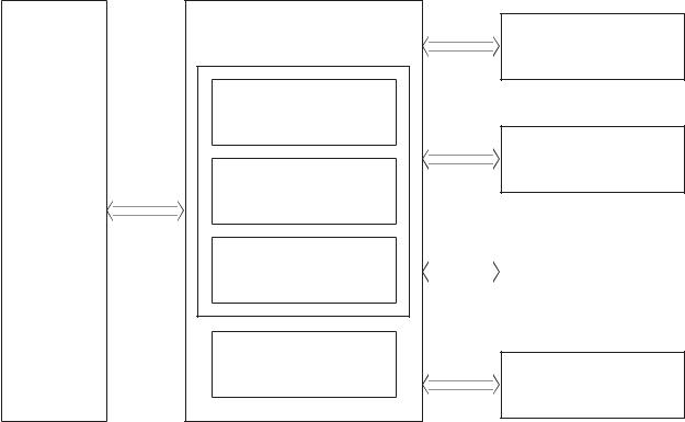
Basic operation
The printer routes all high-level processes through the formatter, which stores font information, processes the print image, and communicates with the host computer.
The basic printer operation comprises the following systems:
●Engine control system
●Laser scanner system
●Image-formation system
●Pickup, feed, and delivery system
●Integrated scanner system (M274 and M277 models only)
Figure 1-1 Basic operation
Laser scanner system
Image-formation system
Engine-control system
Pickup, feed and delivery system
Scanner system (M274 and M277 models only)
ENWW |
Basic operation 3 |

Sequence of operation
The DC controller PCA controls the operating sequence, as described in the following table.
Table 1-1 Sequence of operation
Period |
Duration |
Description |
|
|
|
|
|
Waiting |
From the time the power is turned on, |
● |
Heats the fuser lm in the fuser |
|
the door is closed, or when the printer |
● |
|
|
exits sleep mode until the printer is |
Pressurizes the fuser pressure roller |
|
|
ready for printing |
● |
Detects the toner cartridges |
|
|
||
|
|
● |
Separates all of the developer rollers from the photosensitive |
|
|
|
drums |
|
|
● |
Rotates and stops each motor |
|
|
● |
Rotates and stops the main fan |
|
|
● |
Cleans the intermediate transfer belt (ITB) and secondary |
|
|
|
transfer roller |
|
|
● |
Detects cable breakage on the thermistor |
|
|
● |
Detects any residual paper in the engine |
|
|
|
|
Standby |
From the end of the waiting sequence, |
● |
The printer is in the Ready state |
|
the last rotation until the formatter |
● |
|
|
receives a print command, or until the |
The printer enters sleep mode if the sleep command is received |
|
|
printer is turned o |
|
from the formatter |
|
|
● |
The printer calibrates if it is time for an automatic calibration |
|
|
|
|
Initial rotation |
From the time the formatter receives |
● |
Rotates each motor and the main fan |
|
a print command until the paper |
● |
|
|
enters the paper path |
Activates the high-voltage power supply |
|
|
|
● |
Prepares the laser scanner unit |
|
|
● |
Warms the fuser to the correct temperature |
|
|
|
|
Printing |
From the time the rst sheet of paper |
● |
Forms the image on the photosensitive drums |
|
enters the paper path until the last |
● |
|
|
sheet has passed through the fuser |
Transfers the toner to the paper |
|
|
|
● |
Fuses the toner image onto the paper |
|
|
|
|
Last rotation |
From the time the last sheet of paper |
● |
Moves the last printed sheet into the output bin |
|
exits the fuser until the motors stop |
|
|
|
rotating |
|
|
4 Chapter 1 Theory of operation |
ENWW |

Formatter-control system
The formatter is involved in the following procedures:
●Controlling the sleep delay function
●Receiving and processing print data from the various printer inputs
●Monitoring control-panel functions and relaying printer status information (through the control panel and the bidirectional input/output)
●Developing and coordinating data placement and timing with the DC controller PCA
●Storing font information
●Communicating with the host computer through the bidirectional interface
The formatter receives a print job from the bidirectional interface and separates it into image information and instructions that control the printing process. The DC controller PCA synchronizes the image-formation system with the paper input and output systems, and then signals the formatter to send the print-image data.
Sleep delay
When the printer is in sleep delay mode, the control-panel backlight is turned o , but the printer retains all printer settings, downloaded fonts, and macros. The default setting is a 15-minute idle time. The setting can be changed or turned o from the control panel menus.
The printer exits sleep delay mode and enters the warm-up cycle when any of the following occurs:
●A print job, valid data, or a PML or PJL command is received at the serial port.
●The control panel is touched.
●A document is loaded in the document feeder or the scanner lid is opened.
●A tray is opened.
TIP: Error messages override the sleep delay message. The printer enters sleep mode at the appropriate time, but the error message continues to display.
Printer job language (PJL)
Printer job language (PJL) is an integral part of con guration, in addition to the standard printer command language (PCL). With standard cabling, use PJL to perform a variety of functions.
●Dynamic I/O switching. The printer can be con gured with a host on each I/O by using dynamic I/O switching. Even when the printer is offline, it can receive data from more than one I/O simultaneously,
until the I/O bu er is full.
●Context-sensitive switching. The printer can automatically recognize the personality (PS or PCL) of each job and con gure itself in that personality.
●Isolation of print environment settings from one print job to the next. For example, if a print job is sent to the printer in landscape mode, the subsequent print jobs are printed in landscape mode only if they are formatted for it.
ENWW |
Formatter-control system 5 |
Printer management language (PML)
The printer management language (PML) allows remote con guration and status monitoring through the I/O ports.
Control panel
The formatter sends and receives printer status and command data to and from the control panel.
Walk-up USB (touchscreen models only)
This printer features printing from a USB flash drive. This printer supports printing the following types of les from the USB flash drive:
●.jpg
●.prn and .PRN
●.cht and .CHT
●.pxl
●.pcl and .PCL
●.ps and .PS
●.doc and .docx
●.ppt and .pptx
When a USB flash drive is inserted into the front of the printer, the control panel displays the USB Flash Drive menu. The les present on the USB flash drive can be accessed from the control panel. Any les in a supported format on the USB flash drive can be printed directly from the printer control panel. Pages also can be scanned and saved to the USB flash drive from the control panel.
Wireless (wireless models only)
Wireless models contain a wireless card to enable 802.11b/g/n wireless communication.
Low end data model (LEDM)
The low-end data model (LEDM) provides one consistent data representation method and de nes the dynamic and capabilities tickets shared between clients and devices, as well as the access protocol, event, security, and discovery methods.
Advanced control language (ACL) overview
The advanced control language (ACL) is a language that supports printer control and rmware downloads in printers that support both PJL/PCL and host-based printing. Each sequence of ACL commands must be preceded by a uni ed exit command (UEL) and an @PJL ENTER LANGUAGE=ACL command. The ACL sequence is always followed by a UEL. Any number of commands can be placed between the UELs. The only exception to these rules is the download command. If a rmware download is completed, the download command must be the last command in the sequence. It will not be followed by a UEL.
6 Chapter 1 Theory of operation |
ENWW |
The rmware searches for the UEL sequence when parsing commands. However, while downloading binary data such as host-based code or NVRAM data the rmware suspends UEL parsing. To handle hosts that “disappear” during binary sequences, the rmware times out all ACL command sessions. If a timeout occurs during a non-download command sequence, it is treated as the receipt of a UEL. If a timeout occurs during
rmware download, the printer resets.
Near eld communication (NFC) (wireless models only)
This printer supports near eld communication (NFC) capabilities. NFC enables an easy one-to-one HP wireless direct print connection using a simple device-to-device touch. Mobile device users can quickly connect to the printer and print documents and images from a mobile device, such as a smartphone or tablet, by touching the device to the NFC icon on the printer.
CPU
The formatter incorporates an 800 MHz processor.
Input/output
The following sections discuss the input and output features of the printer.
USB
The printer includes a universal serial bus (USB) 2.0 connection.
USB hosts
The printer includes USB hosts for USB flash drive and wireless communication control.
10/100 networking
The printer includes a 10/100 network (ethernet) connection.
Fax (M277 models only)
The M277 models include a fax phone line connection.
Memory
If the printer encounters a problem when managing available memory, a clearable warning message displays on the control panel.
Firmware
Memory on the formatter stores the rmware. A remote rmware upgrade process is used to overwrite and upgrade the rmware.
Nonvolatile random access memory (NVRAM)
The printer uses nonvolatile memory (NVRAM) to store I/O and information about the print environment con guration. The contents of NVRAM are retained when the printer is turned o or disconnected.
Flash memory
NOR: Stores microprocessor control programs and internal character sets (fonts).
ENWW |
Formatter-control system 7 |

NAND: Stores fax memory (M277 models only) and driver installation software.
Random access memory (RAM)
The M252n model comes with 128 MB of memory installed. All other models come with 256 MB of memory installed. The formatter has 256 MB NAND Flash.
HP Memory enhancement technology (MEt)
The HP Memory Enhancement technology (MEt) e ectively doubles the standard memory through a variety of fontand data-compression methods.
 NOTE: The MEt is available only in PCL mode; it is not functional when printing in PS mode.
8 Chapter 1 Theory of operation |
ENWW |
Engine-control system
The engine-control system receives commands from the formatter and coordinates all the other systems. The engine-control system contains the following components:
●Engine control unit: DC controller and high-voltage power supply
●Low-voltage power supply
●Fuser control
Figure 1-2 Engine-control system
Formatter-control system |
|
Engine controller |
Laser scanner system |
DC controller
Image-formation system
High-voltage power supply
Formatter
Fuser control |
|
|
Pickup, feed and delivery |
|
|
system |
|
|
|
|
|
|
|
|
|
Low-voltage power supply
Scanner system (M274, M277 models only)
The formatter receives a print job from the bidirectional interface and separates it into image information and instructions that control the printing process. The DC controller PCA synchronizes the image-formation system with the paper input and output systems, and then signals the formatter to send the print-image data.
ENWW |
Engine-control system 9 |

Engine control unit (ECU) |
|
|
The engine control unit includes the DC controller and the high-voltage power supply. |
||
Figure 1-3 Engine control unit |
|
|
|
Engine control unit |
|
Secondary |
|
Fan |
transfer roller |
|
|
|
|
|
Cartridge |
High-voltage |
Motor |
|
||
(Y/M/C/K) |
|
|
power supply |
|
|
|
|
|
|
|
Solenoid |
ITB assembly |
|
|
|
|
Switch |
|
|
Photointerrupter |
|
|
Sensor |
|
|
LED |
|
DC controller |
|
|
|
Control panel |
|
Fuser |
Formatter |
|
|
|
Motor |
Low-voltage |
Laser scanner |
power supply |
||
|
|
assembly |
AC input |
|
|
DC controller
The DC controller PCA controls the operation of the printer and its components. The DC controller PCA starts printer operation when the power is turned on and the power supply sends DC voltage to the DC controller PCA. After the printer enters the standby sequence, the DC controller PCA sends out various signals to operate motors, solenoids, and other electrical components based on the print command and image data that the host computer sends.
10 Chapter 1 Theory of operation |
ENWW |
Loading...