


 Loading...
Maintenance & Service Guide
HP Compaq 8200 Elite All-in-One Business PC
© Copyright 2011 Hewlett-Packard Development Company, L.P. The information contained herein is subject to change without notice.
Microsoft and Windows are trademarks of Microsoft Corporation in the U.S. and other countries.
The only warranties for HP products and services are set forth in the express warranty statements accompanying such products and services. Nothing herein should be construed as constituting an additional warranty. HP shall not be liable for technical or editorial errors or omissions contained herein.
This document contains proprietary information that is protected by copyright. No part of this document may be photocopied, reproduced, or translated to another language without the prior written consent of Hewlett-Packard Company.
Maintenance & Service Guide
HP Compaq 8200 Elite All-in-One Business
PC
First Edition (August 2011)
Document Part Number: 670568-001

About This Book
WARNING! Text set off in this manner indicates that failure to follow directions could result in bodily harm or loss of life.
CAUTION: Text set off in this manner indicates that failure to follow directions could result in damage to equipment or loss of information.
 NOTE: Text set off in this manner provides important supplemental information.
iii
iv About This Book

Table of contents
1 Product Features ............................................................................................................................................ |
1 |
Overview .............................................................................................................................................. |
1 |
Front Components ................................................................................................................................ |
3 |
Side Components ................................................................................................................................. |
4 |
Rear Components ................................................................................................................................ |
5 |
Adjusting Tilt ......................................................................................................................................... |
6 |
2 Installing and Customizing the Software ...................................................................................................... |
7 |
Installing the Operating System ........................................................................................................... |
7 |
Downloading Microsoft Windows Updates ........................................................................................... |
7 |
Installing or Upgrading Device Drivers (Windows systems) ................................................................. |
8 |
Accessing Disk Image (ISO) Files ........................................................................................................ |
8 |
Protecting the Software ........................................................................................................................ |
8 |
3 Computer Setup (F10) Utility ......................................................................................................................... |
9 |
Computer Setup (F10) Utilities ............................................................................................................. |
9 |
Using Computer Setup (F10) Utilities ................................................................................ |
10 |
Computer Setup—File ....................................................................................................... |
11 |
Computer Setup—Storage ................................................................................................ |
12 |
Computer Setup—Security ................................................................................................ |
14 |
Computer Setup—Power ................................................................................................... |
17 |
Computer Setup—Advanced ............................................................................................. |
18 |
4 Serial ATA (SATA) Drive Guidelines and Features .................................................................................... |
20 |
SATA Hard Drives .............................................................................................................................. |
20 |
SATA Hard Drive Cables .................................................................................................................... |
20 |
SATA Data Cable .............................................................................................................. |
20 |
SMART ATA Drives ............................................................................................................................ |
21 |
Hard Drive Capacities ........................................................................................................................ |
21 |
v
5 Identifying the Chassis, Routine Care, and Disassembly Preparation .................................................... |
22 |
Chassis Designation ........................................................................................................................... |
22 |
All-in One ........................................................................................................................... |
22 |
Electrostatic Discharge Information .................................................................................................... |
23 |
Generating Static ............................................................................................................... |
23 |
Preventing Electrostatic Damage to Equipment ................................................................ |
23 |
Personal Grounding Methods and Equipment ................................................................... |
24 |
Grounding the Work Area .................................................................................................. |
24 |
Recommended Materials and Equipment .......................................................................... |
24 |
Operating Guidelines .......................................................................................................................... |
25 |
Routine Care ...................................................................................................................................... |
26 |
General Cleaning Safety Precautions ................................................................................ |
26 |
Cleaning the Computer Case ............................................................................................ |
26 |
Cleaning the Keyboard ...................................................................................................... |
26 |
Cleaning the Monitor .......................................................................................................... |
27 |
Cleaning the Mouse ........................................................................................................... |
27 |
Service Considerations ...................................................................................................................... |
27 |
Tools and Software Requirements .................................................................................... |
27 |
Screws ............................................................................................................................... |
27 |
Cables and Connectors ..................................................................................................... |
28 |
Hard Drives ........................................................................................................................ |
28 |
Lithium Coin Cell Battery ................................................................................................... |
28 |
6 Removal and Replacement Procedures All-in One (AIO) Chassis ........................................................... |
29 |
Preparing to Disassemble the Computer ........................................................................................... |
29 |
Synchronizing the Optional Wireless Keyboard or Mouse ................................................................. |
30 |
Center Access Panel .......................................................................................................................... |
32 |
Stand .................................................................................................................................................. |
33 |
Memory Access Panel ........................................................................................................................ |
34 |
Drive Access Panel ............................................................................................................................ |
35 |
Optical Drive ....................................................................................................................................... |
37 |
Hard Drive .......................................................................................................................................... |
39 |
Memory .............................................................................................................................................. |
42 |
Top Panel ........................................................................................................................................... |
45 |
Webcam Module ................................................................................................................................ |
46 |
Rear Cover ......................................................................................................................................... |
48 |
System Board Cover .......................................................................................................................... |
49 |
Sidekey Board .................................................................................................................................... |
51 |
Converter Board ................................................................................................................................. |
54 |
Speakers ............................................................................................................................................ |
56 |
WLAN Module .................................................................................................................................... |
57 |
vi
Heat Sink (Thermal Module) .............................................................................................................. |
59 |
Processor ........................................................................................................................................... |
61 |
Fan Assembly ..................................................................................................................................... |
63 |
Display Cable ..................................................................................................................................... |
65 |
System Board ..................................................................................................................................... |
67 |
Stand Bracket ..................................................................................................................................... |
71 |
Hard Drive and Optical Drive Cables and Connectors ....................................................................... |
73 |
Front Bezel ......................................................................................................................................... |
75 |
Display Panel ..................................................................................................................................... |
76 |
Appendix A Password Security and Resetting CMOS ................................................................................. |
81 |
Establishing a Setup or Power-on Password ..................................................................................... |
82 |
Resetting a Setup or Power-on Password ......................................................................................... |
83 |
Clearing and Resetting the CMOS ..................................................................................................... |
84 |
Appendix B POST Error Messages ................................................................................................................ |
86 |
POST Numeric Codes and Text Messages ....................................................................................... |
87 |
Interpreting POST Diagnostic Front Panel LEDs and Audible Codes ................................................ |
94 |
Appendix C Troubleshooting Without Diagnostics ...................................................................................... |
97 |
Safety and Comfort ............................................................................................................................ |
97 |
Solving General Problems .................................................................................................................. |
98 |
Solving Power Problems .................................................................................................................. |
101 |
Solving Diskette Problems ............................................................................................................... |
102 |
Solving Hard Drive Problems ........................................................................................................... |
104 |
Solving Media Card Reader Problems ............................................................................................. |
107 |
Solving Display Problems ................................................................................................................. |
108 |
Solving Audio Problems ................................................................................................................... |
112 |
Solving Printer Problems .................................................................................................................. |
114 |
Solving Keyboard and Mouse Problems .......................................................................................... |
114 |
Solving Hardware Installation Problems ........................................................................................... |
117 |
Solving Network Problems ............................................................................................................... |
118 |
Solving Memory Problems ............................................................................................................... |
121 |
Solving Processor Problems ............................................................................................................ |
122 |
Solving CD-ROM and DVD Problems .............................................................................................. |
123 |
Solving USB Flash Drive Problems .................................................................................................. |
125 |
Solving Internet Access Problems .................................................................................................... |
126 |
Solving Software Problems .............................................................................................................. |
128 |
Contacting Customer Support .......................................................................................................... |
129 |
vii
Appendix D Connector Pin Assignments .................................................................................................... |
130 |
Ethernet BNC ................................................................................................................................... |
130 |
USB .................................................................................................................................................. |
130 |
Microphone ....................................................................................................................................... |
130 |
Headphone ....................................................................................................................................... |
131 |
Line-in Audio .................................................................................................................................... |
131 |
Line-out Audio .................................................................................................................................. |
131 |
Appendix E Power Cord Set Requirements ................................................................................................ |
132 |
General Requirements ..................................................................................................................... |
132 |
Japanese Power Cord Requirements .............................................................................................. |
132 |
Country-Specific Requirements ........................................................................................................ |
133 |
Appendix F Specifications ............................................................................................................................ |
134 |
All-in One Models ............................................................................................................................. |
134 |
Index ................................................................................................................................................................. |
135 |
viii
1 Product Features
Overview
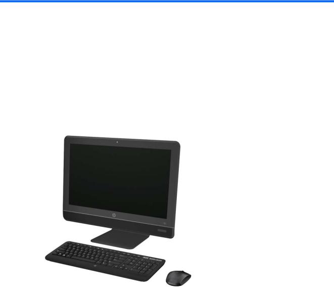
Figure 1-1 HP Compaq 8200 Elite All-in-One Business PC
The HP Compaq 8200 Elite All-In One Business PC offers the following features:
●Integrated All-in-One form factor
●23-inch diagonal widescreen, full HD, LED, anti-glare display
●Adjustable tilt
●Second generation Intel® Core™ i processors and Intel Pentium processors
●Intel Q67 chipset
●Windows 7 Professional 32or 64-bit, FreeDOS, or FreeLnx operating system
●Integrated Intel HD Graphics
●Integrated Gigabit Network Connection
●Up to 8 GB of DDR3 SDRAM memory
Overview 1
●Up to 1-TB hard drive, 320-GB Self Encrypting Drive, or 160-GB solid state drive
●HP Blu-ray Combo Drive
●6-in-1 Media Card Reader
●6 USB ports
●150W, 90% efficient external, active PFC power adapter
●1.3-MP webcam, microphone, and stereo speakers
●HP 802.11 a/b/g/n PCIe Minicard Wireless Module and Bluetooth® Combo available as an option
●High-definition audio support, internal stereo speakers, microphone and headphone ports
●Certifications: UL, CSA, FCC Compliance, ENERGY STAR®, EPEAT® Silver, EUP Lot6 Tier2
●HP USB Keyboard and HP USB Optical Scroll Mouse
●Software: HP ProtectTools12; Microsoft® Office 2010 Preloaded - Purchase Key13, HP Power Assistant14, Norton Internet Security 201115, PDF Complete Corporate Edition
2 Chapter 1 Product Features
Front Components
Figure 1-2 Front Components
Table 1-1 Front Components
Component |
Component |
||
|
|
|
|
(1) |
Webcam |
(4) |
Power button and LED |
|
|
|
|
(2) |
Single microphone array |
(5) |
High-performance stereo speakers |
(3)23-inch diagonal 16:9 widescreen LED-backlit full HD LCD display
Front Components |
3 |
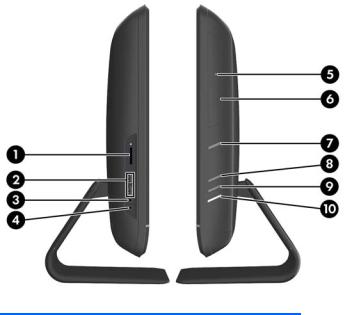
Side Components
Figure 1-3 Side Components
Table 1-2 Side Components
Component |
Component |
||
|
|
|
|
(1) |
HP 6-in-1 Media Card Reader |
(6) |
Tray-load optical drive |
|
|
|
|
(2) |
(2) USB 2.0 ports |
(7) |
Optical drive eject button |
|
|
|
|
(3) |
Microphone/line in jack |
(8) |
Brightness increase button |
|
|
|
|
(4) |
Headphone jack |
(9) |
Brightness decrease button |
|
|
|
|
(5) |
Optical drive activity LED |
(10) |
Hard drive activity LED |
|
|
|
|
4 Chapter 1 Product Features
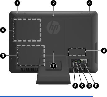
Rear Components
Figure 1-4 Rear Components
Table 1-3 Rear Components
Component |
Component |
||
|
|
|
|
(1) |
Drive access panel |
(7) |
Security lock slot |
|
|
|
|
(2) |
Center access panel |
(8) |
Power connector with LED indicator |
|
|
|
|
(3) |
Memory access panel |
(9) |
RJ-45 Gigabit Ethernet port |
|
|
|
|
(4) |
Optical drive location |
(10) |
Stereo audio line out |
|
|
|
|
(5) |
Hard drive location |
(11) |
(4) USB 2.0 ports |
|
|
|
|
(6) |
Memory location |
|
|
|
|
|
|
Rear Components |
5 |
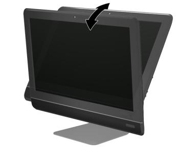
Adjusting Tilt
Tilt the computer forward up to 5 degrees or backward up to 20 degrees to set it to a comfortable eye level.
Figure 1-5 Adjusting Tilt
6 Chapter 1 Product Features

2Installing and Customizing the Software
If your computer was not shipped with a Microsoft operating system, some portions of this documentation do not apply. Additional information is available in online help after you install the operating system.


 NOTE: If the computer was shipped with Windows 7 loaded, you will be prompted to register the computer with HP Total Care before installing the operating system. You will see a brief movie followed by an online registration form. Fill out the form, click the Begin button, and follow the instructions on the screen.
CAUTION: Do not add optional hardware or third-party devices to the computer until the operating system is successfully installed. Doing so may cause errors and prevent the operating system from installing properly.


 NOTE: Be sure there is a 10.2-cm (4-inch) clearance at the back of the unit and above the monitor to permit the required airflow.
Installing the Operating System
The first time you turn on the computer, the operating system is installed automatically. This process takes about 5 to 10 minutes, depending on which operating system is being installed. Carefully read and follow the instructions on the screen to complete the installation.
CAUTION: Once the automatic installation has begun, DO NOT TURN OFF THE COMPUTER UNTIL THE PROCESS IS COMPLETE. Turning off the computer during the installation process may damage the software that runs the computer or prevent its proper installation.


 NOTE: If the computer shipped with more than one operating system language on the hard drive, the installation process could take up to 60 minutes.
If your computer was not shipped with a Microsoft operating system, some portions of this documentation do not apply. Additional information is available in online help after you install the operating system.
Downloading Microsoft Windows Updates
1.To set up your Internet connection, click Start > Internet Explorer and follow the instructions on the screen.
2.Once an Internet connection has been established, click the Start button.
Installing the Operating System |
7 |
3.Select the All Programs menu.
4.Click on the Windows Update link.
In Windows 7, the Windows Update screen appears. Click view available updates and make sure all critical updates are selected. Click the Install button and follow the instructions on the screen.
It is recommended that you install all of the critical updates and service packs.
5.After the updates have been installed, Windows will prompt you to reboot the machine. Be sure to save any files or documents that you may have open before rebooting. Then select Yes to reboot the machine.
Installing or Upgrading Device Drivers (Windows systems)
When installing optional hardware devices after the operating system installation is complete, you must also install the drivers for each of the devices.
If prompted for the i386 directory, replace the path specification with C:\i386, or use the Browse button in the dialog box to locate the i386 folder. This action points the operating system to the appropriate drivers.
Obtain the latest support software, including support software for the operating system from http://www.hp.com/support. Select your country and language, select Download drivers and software (and firmware), enter the model number of the computer, and press Enter.
Accessing Disk Image (ISO) Files
There are disk image files (ISO files) included on your PC that contain the installation software for additional software. These CD image files are located in the folder C:\SWSetup\ISOs. Each .iso file can be burned to CD media to create an installation CD. It is recommended that these disks be created and the software installed in order to get the most from your PC. The software and image file names are:
●Corel WinDVD SD and BD – installation software for WinDVD – used to play DVD movies
●HP Insight Diagnostics OR Vision Diagnostics – software to perform diagnostic activities on your PC
Protecting the Software
To protect the software from loss or damage, keep a backup copy of all system software, applications, and related files stored on the hard drive. Refer to the operating system or backup utility documentation for instructions on making backup copies of your data files.
8 |
Chapter 2 Installing and Customizing the Software |

3 Computer Setup (F10) Utility
Computer Setup (F10) Utilities
Use Computer Setup (F10) Utility to do the following:
●Change factory default settings.
●Set the system date and time.
●Set, view, change, or verify the system configuration, including settings for processor, graphics, memory, audio, storage, communications, and input devices.
●Modify the boot order of bootable devices such as hard drives, optical drives, or USB flash media devices.
●Enable Quick Boot, which is faster than Full Boot but does not run all of the diagnostic tests run during a Full Boot. You can set the system to:
always Quick Boot (default);
periodically Full Boot (from every 1 to 30 days); or
always Full Boot.
●Select Post Messages Enabled or Disabled to change the display status of Power-On Self-Test (POST) messages. Post Messages Disabled suppresses most POST messages, such as memory count, product name, and other non-error text messages. If a POST error occurs, the error is displayed regardless of the mode selected. To manually switch to Post Messages Enabled during POST, press any key (except F1 through F12).
●Establish an Ownership Tag, the text of which is displayed each time the system is turned on or restarted.
●Enter the Asset Tag or property identification number assigned by the company to this computer.
●Enable the power-on password prompt during system restarts (warm boots) as well as during power-on.
●Establish a setup password that controls access to the Computer Setup (F10) Utility and the settings described in this section.
●Secure integrated I/O functionality, including USB, audio, or embedded NIC, so that they cannot be used until they are unsecured.
●Enable or disable removable media boot ability.
Computer Setup (F10) Utilities |
9 |

●Solve system configuration errors detected but not automatically fixed during the Power-On SelfTest (POST).
●Replicate the system setup by saving system configuration information on a USB flash drive and restoring it on one or more computers.
●Execute self-tests on a specified ATA hard drive (when supported by drive).
●Enable or disable DriveLock security (when supported by drive).
Using Computer Setup (F10) Utilities
Computer Setup can be accessed only by turning the computer on or restarting the system. To access the Computer Setup Utilities menu, complete the following steps:
1.Turn on or restart the computer.
2.Press Esc while the “Press the ESC key for Startup Menu” message is displayed at the bottom of the screen.


 NOTE: If you do not press Esc at the appropriate time, you must restart the computer and again press Esc when the monitor light turns green to access the utility.
3.Press F10 to enter Computer Setup.
4.A choice of five headings appears in the Computer Setup Utilities menu: File, Storage, Security, Power, and Advanced.
5.Use the arrow (left and right) keys to select the appropriate heading. Use the arrow (up and down) keys to select the option you want, then press Enter. To return to the Computer Setup Utilities menu, press Esc.
6.To apply and save changes, select File > Save Changes and Exit.
●If you have made changes that you do not want applied, select Ignore Changes and Exit.
●To reset to factory settings or previously saved default settings (some models), select Apply Defaults and Exit. This option will restore the original factory system defaults.
CAUTION: Do NOT turn the computer power OFF while the BIOS is saving the Computer Setup (F10) changes because the CMOS could become corrupted. It is safe to turn off the computer only after exiting the F10 Setup screen.
10 Chapter 3 Computer Setup (F10) Utility

Computer Setup—File


 NOTE: Support for specific Computer Setup options may vary depending on the hardware configuration.
Table 3-1 Computer Setup—File
Option |
Description |
|
|
|
|
System Information |
Lists: |
|
|
● |
Product name |
|
● SKU number (some models) |
|
|
● |
Processor type/speed/stepping |
|
● |
Cache size (L1/L2/L3) |
|
● Installed memory size/speed, number of channels (single or dual) (if applicable) |
|
|
● Integrated MAC address for embedded, enabled NIC (if applicable) |
|
|
● System BIOS (includes family name and version) |
|
|
● |
Chassis serial number |
|
● |
Asset Tracking Number |
|
● |
ME Firmware Version |
|
● |
ME Management Mode |
|
|
|
About |
Displays copyright notice. |
|
|
|
|
Set Time and Date |
Allows you to set system time and date. |
|
|
|
|
Flash System ROM |
Allows you to update the system ROM with a BIOS image file located on removable media. |
|
|
|
|
Replicated Setup |
Save to Removable Media |
|
|
Saves system configuration, including CMOS, to a formatted 1.44-MB diskette, a USB flash media |
|
|
device, or a diskette-like device (a storage device set to emulate a diskette drive). |
|
|
Restore from Removable Media |
|
|
Restores system configuration from a diskette, a USB flash media device, or a diskette-like |
|
|
device. |
|
|
|
|
Default Setup |
Save Current Settings as Default |
|
|
Saves the current system configuration settings as the default. |
|
|
Restore Factory Settings as Default |
|
|
Restores the factory system configuration settings as the default. |
|
|
|
|
Apply Defaults and |
Applies the currently selected default settings and clears any established passwords. |
|
Exit |
|
|
|
|
|
Ignore Changes |
Exits Computer Setup without applying or saving any changes. |
|
and Exit |
|
|
|
|
|
Save Changes and |
Saves changes to system configuration or default settings and exits Computer Setup. |
|
Exit |
|
|
|
|
|
Computer Setup (F10) Utilities 11

Computer Setup—Storage


 NOTE: Support for specific Computer Setup options may vary depending on the hardware configuration.
Table 3-2 Computer Setup—Storage
Option |
Description |
|
|
Device Configuration |
Lists all installed BIOS-controlled storage devices. |
|
When a device is selected, detailed information and options are displayed. The following options |
|
may be presented: |
|
Hard Disk: Size, model, firmware, serial number, connector color, SMART, translation mode. |
|
Translation mode lets you select the translation mode to be used for the device. This enables the |
|
BIOS to access disks partitioned and formatted on other systems and may be necessary for users |
|
of older versions of UNIX (e.g., SCO UNIX version 3.2). Options are Automatic, Bit-Shift, LBA |
|
Assisted, User, and None. |
|
CAUTION: Ordinarily, the translation mode selected automatically by the BIOS should not be |
|
changed. If the selected translation mode is not compatible with the translation mode that was |
|
active when the disk was partitioned and formatted, the data on the disk will be inaccessible. |
|
Translation parameters (ATA disks only; this feature appears only when User translation mode |
|
is selected.): Allows you to specify the parameters (logical cylinders, heads, and sectors per track) |
|
used by the BIOS to translate disk I/O requests (from the operating system or an application) into |
|
terms the hard drive can accept. Logical cylinders may not exceed 1024. The number of heads |
|
may not exceed 256. The number of sectors per track may not exceed 63. These fields are only |
|
visible and changeable when the drive translation mode is set to User. |
|
Default Values: Allows you to specify the default values for the Multisector Transfers, Transfer |
|
Mode, and Translation Mode for ATA devices. |
|
CD-ROM: Model, firmware, serial number, connector color. No emulation options available. |
|
|
Storage Options |
Removable Media Boot |
|
Enables/disables ability to boot the system from removable media. Default is enable. |
|
SATA Emulation |
|
Allows you to choose how the SATA controller and devices are accessed by the operating |
|
system. There are two supported options: AHCI and IDE. |
|
AHCI (default option) - Allows operating systems with AHCI device drivers loaded to take |
|
advantage of more advanced features of the SATA controller. |
|
IDE - This is the most backwards-compatible setting of the two options. Operating systems usually |
|
do not require additional driver support in IDE mode. |
|
NOTE: The AHCI device driver must be installed prior to attempting to boot from an AHCI |
|
volume. If you attempt to boot from an AHCI volume without the required device driver installed, |
|
the system will crash (blue screen). |
|
|
12 Chapter 3 Computer Setup (F10) Utility
Table 3-2 Computer Setup—Storage (continued)
DPS Self-Test |
Allows you to execute self-tests on ATA hard drives capable of performing the Drive Protection |
|
System (DPS) self-tests. |
|
NOTE: This selection will only appear when at least one drive capable of performing the DPS |
|
self-tests is attached to the system. |
|
|
Boot Order |
Allows you to: |
|
● Specify the order in which EFI boot sources and legacy boot sources (such as a USB flash |
|
media device, hard drive, optical drive, or network interface card) are checked for a bootable |
|
operating system image. Each device on the list may be individually excluded from or |
|
included for consideration as a bootable operating system source. |
|
● Specify the order of attached hard drives. The first hard drive in the order will have priority in |
|
the boot sequence and will be recognized as drive C (if any devices are attached). |
|
Press F5 to disable a device. Press Enter to select a device. Press the arrow keys to drag a |
|
selected device. |
|
NOTE: MS-DOS drive lettering assignments may not apply after a non-MS-DOS operating |
|
system has started. |
|
Shortcut to Temporarily Override Boot Order |
|
To boot one time from a device other than the default device specified in Boot Order, restart the |
|
computer and press F9 before the computer boots to the operating system. After POST is |
|
completed, a list of bootable devices is displayed. Use the arrow keys to select the preferred |
|
bootable device and press Enter. The computer then boots from the selected non-default device |
|
for this one time. |
|
|
Computer Setup (F10) Utilities 13

Computer Setup—Security


 NOTE: Support for specific Computer Setup options may vary depending on the hardware configuration.
Table 3-3 Computer Setup—Security
Option |
Description |
||
|
|
||
Setup Password |
Allows you to set and enable a setup (administrator) password. |
||
|
NOTE: If the setup password is set, it is required to change Computer Setup options, flash the |
||
|
ROM, and make changes to certain plug and play settings under Windows. |
||
|
See the Desktop Management Guide for more information. |
||
|
|
||
Power-On Password |
Allows you to set and enable a power-on password. The power-on password prompt appears |
||
|
after a power cycle. If the user does not enter the correct power-on password, the unit will not |
||
|
boot. |
|
|
|
NOTE: This password does not appear on warm boots , such as Ctrl+Alt+Delete or Restart |
||
|
from Windows, unless enabled in Password Options (see below). |
||
|
See the Desktop Management Guide for more information. |
||
|
|
||
Password Options |
Allows you to: |
||
(Appears only if a |
● Lock legacy resources (appears if a setup password is set). Default is enable. |
||
power-on password or |
● Enable/Disable Setup Browse Mode (appears if a setup password is set) (allows viewing, but |
||
setup password is set.) |
|||
|
|
not changing, the F10 Setup Options without entering setup password). Default is enable. |
|
|
● Specify whether the password is required for warm boot (Ctrl+Alt+Delete) (appears if a |
||
|
|
power-on password is set). Default is enable. |
|
|
● Enable/disable network server mode (appears if a power-on password is set). Default is |
||
|
|
disable. |
|
|
|
||
Device Security |
Allows you to set Device Available/Device Hidden for: |
||
|
● |
Embedded Security Device |
|
|
● |
System Audio |
|
|
● Network Controller (some models) |
||
|
● |
SATA0 |
|
|
● |
SATA1 |
|
|
|
||
USB Security |
Allows you to enable or disable groups of USB ports or individual USB ports. Default is device |
||
|
available. |
|
|
|
● |
Front USB Ports |
|
|
|
◦ |
USB Port 1 |
|
|
◦ |
USB Port 2 |
|
● |
Rear USB Ports |
|
|
|
◦ |
USB Port 1 |
|
|
◦ |
USB Port 2 |
14 Chapter 3 Computer Setup (F10) Utility

Table 3-3 Computer Setup—Security (continued)
|
◦ |
USB Port 3 |
|
◦ |
USB Port 4 |
|
● internal USB Ports |
|
|
◦ |
USB Port 1 |
|
◦ |
USB Port 2 |
|
◦ |
USB Port 3 |
|
◦ |
USB Port 10 |
|
|
|
Slot Security |
Allows you to disable or enable the PCI Express x1 slot. Default is enable. |
|
|
|
|
Network Boot |
Enables/disables the computer’s ability to boot from an operating system installed on a network |
|
|
server. (Feature available on NIC models only; the network controller must be either a PCI |
|
|
Express expansion card or embedded on the system board.) Default is enable. |
|
|
|
|
System IDs |
Allows you to update: |
|
|
● Asset tag (18-byte identifier). |
|
|
● Ownership tag (80-byte identifier displayed during POST). |
|
|
● Chassis serial number or Universal Unique Identifier (UUID) number. The UUID can only be |
|
updated if the current chassis serial number is invalid. (These ID numbers are normally set in the factory and are used to uniquely identify the system.)
● Keyboard locale setting (for example, English or German) for System ID entry.
Computer Setup (F10) Utilities 15

Table 3-3 Computer Setup—Security (continued)
System Security |
Data Execution Prevention (some models) (enable/disable) - Helps prevent operating system |
(some models: these |
security breaches. Default is enabled. |
options are hardware |
PAVP (Models with Blu-ray drives) (disabled/min/max) - PAVP enables the Protected Audio Video |
dependent) |
|
|
Path in the Chipset. This may allow viewing of some protected high definition content that would |
|
otherwise be prohibited from playback. Selecting Max will assign 96 Megabytes of system |
|
memory exclusively to PAVP. |
|
Virtualization Technology (VTx) (some models) (enable/disable) - Controls the virtualization |
|
features of the processor. Changing this setting requires turning the computer off and then back |
|
on. Default is disabled. |
|
Virtualization Technology Directed I/O (VTd) (some models) (enable/disable) - Controls |
|
virtualization DMA remapping features of the chipset. Changing this setting requires turning the |
|
computer off and then back on. Default is disabled. |
|
Intel TXT (LT) Support (some models) (enable/disable) - Controls the underlying processor and |
|
chipset features needed to support a virtual appliance. Changing this setting requires turning the |
|
computer off and then back on. Default is disabled. To enable this feature you must enable the |
|
following features: |
|
● Embedded Security Device Support |
|
● Virtualization Technology |
|
● Virtualization Technology Directed I/O |
|
Embedded Security Device (some models) (enable/disable) - Permits activation and deactivation |
|
of the Embedded Security Device. Changing this setting requires turning the computer off and |
|
then back on. |
|
NOTE: To configure the Embedded Security Device, a Setup password must be set. |
|
● Reset to Factory Settings (some models) (Do not reset/Reset) - Resetting to factory defaults |
|
will erase all security keys. Changing this setting requires turning the computer off and then |
|
back on. Default is Do not reset. |
|
CAUTION: The embedded security device is a critical component of many security |
|
schemes. Erasing the security keys will prevent access to data protected by the Embedded |
|
Security Device. Choosing Reset to Factory Settings may result in significant data loss. |
|
OS management of Embedded Security Device (some models) (enable/disable) - This option |
|
allows the user to limit operating system control of the Embedded Security Device. Changing this |
|
setting requires turning the computer off and then back on. This option allows the user to limit OS |
|
control of the Embedded Security Device. Default is enable. |
|
● Reset of Embedded Security Device through OS (some models) (enable/disable) - This |
|
option allows the user to limit the operating system ability to request a Reset to Factory |
|
Settings of the Embedded Security Device. Changing this setting requires turning the |
|
computer off and then back on. Default is disable. |
|
NOTE: To enable this option, a Setup password must be set. |
|
|
DriveLock Security |
Allows you to assign or modify a master or user password for hard drives. When this feature is |
|
enabled, the user is prompted to provide one of the DriveLock passwords during POST. If neither |
|
is successfully entered, the hard drive will remain inaccessible until one of the passwords is |
|
successfully provided during a subsequent cold-boot sequence. |
|
NOTE: This selection will only appear when at least one drive that supports the DriveLock |
|
feature is attached to the system. |
|
|
16 Chapter 3 Computer Setup (F10) Utility

Computer Setup—Power


 NOTE: Support for specific Computer Setup options may vary depending on the hardware configuration.
Table 3-4 Computer Setup—Power
Option |
Description |
|
|
|
|
OS Power |
● Runtime Power Management— Enable/Disable. Allows certain operating systems to reduce |
|
Management |
processor voltage and frequency when the current software load does not require the full |
|
|
capabilities of the processor. Default is enabled. |
|
|
● Idle Power Savings—Extended/Normal. Allows certain operating systems to decrease the |
|
|
processors power consumption when the processor is idle. Default is extended. |
|
|
● USB Wake on Device Insertion (some models)—Allows system to wake from Standby on |
|
|
USB device insertion. |
|
|
● Unique Sleep State Blink Rates—Enable/Disable. This feature is designed to provide a |
|
|
visual indication of what sleep state the system is in. Each sleep state has a unique blink |
|
|
pattern. Default is disabled. |
|
|
◦ |
S0 (On) = Solid green LED. |
|
◦ |
S3 (Stand By)= 3 blinks at 1Hz (50% duty cycle) followed by a pause of 2 seconds |
|
|
(green LED) — repeated cycles of 3 blinks and a pause. |
|
◦ |
S4 (Hibernation)= 4 blinks at 1Hz (50% duty cycle) followed by a pause of 2 seconds |
|
|
(green LED) — repeated cycles of 4 blinks and a pause. |
|
◦ |
S5 (Soft Off) = LED is off. |
|
NOTE: If this feature is disabled, S4 and S5 both have the LED off. S1 (no longer supported) |
|
|
and S3 use 1 blink per second. |
|
|
|
|
Hardware Power |
● SATA Power Management—Enables or disables the SATA bus and/or device power |
|
Management |
management. Default is enabled. |
|
|
● S5 Maximum Power Savings—Turns off power to all nonessential hardware when system is |
|
|
off to meet EUP Lot 6 requirement of less than 1 Watt power usage. Enabling this feature will |
|
|
disable any wake events and management devices while in S5. Default is disabled. |
|
|
|
|
Thermal |
Displays the system fan speed (RPMs). |
|
|
|
|
Computer Setup (F10) Utilities 17

Computer Setup—Advanced


 NOTE: Support for specific Computer Setup options may vary depending on the hardware configuration.
Table 3-5 Computer Setup—Advanced
Option |
Heading |
|
|
|
|
Power-On Options |
Allows you to set: |
|
|
● POST mode (QuickBoot, Clear Memory, FullBoot, or FullBoot Every x Days). |
|
|
◦ |
QuickBoot (default) = Do not clear memory or perform a memory test. |
|
◦ |
FullBoot = Memory test (count) on cold boot. Clears memory on all boots. |
|
◦ |
Clear Memory = No memory count on cold boot. Clears memory on all boots. |
|
◦ |
FullBoot Every x Days = Memory count on 1st cold boot on or after the xth day. No |
|
|
more memory counts until 1st cold boot on or after x days. Clears memory on all boots. |
|
● POST messages (enable/disable). Suppresses most POST messages, such as memory |
|
|
count, product name, and other non-error text messages. If a POST error occurs, the error is |
|
|
displayed regardless of the mode selected. |
|
|
● Press the ESC key for Startup Menu (Enable/Disable). Default is enabled. |
|
|
● After Power Loss (off/on/previous state): Setting this option to: |
|
|
◦ |
Power Off—causes the computer to remain powered off when power is restored. |
|
◦ |
Power On—causes the computer to power on automatically as soon as power is |
|
|
restored. |
|
◦ |
Previous state—causes the computer to power on automatically as soon as power is |
|
|
restored, if it was on when power was lost. |
|
NOTE: If you turn off power to the computer using the switch on a power strip, you will not be |
|
|
able to use the suspend/sleep feature or the Remote Management features. |
|
|
● POST Delay (None, 5, 10 15, or 20 seconds). Enabling this feature will add a user-specified |
|
|
delay to the POST process. This delay is sometimes needed for hard disks on some PCI |
|
|
cards that spin up very slowly, so slowly that they are not ready to boot by the time POST is |
|
|
finished. The POST delay also gives you more time to select F10 to enter Computer (F10) |
|
|
Setup. |
|
|
● Remote Wakeup Boot Source (remote server/local hard drive). Default is Local hard drive. |
|
|
● System Recovery Boot Support (Enable/Disable). Setting this feature to enabled will display |
|
|
the text F11 = Recovery during POST. Disabling the feature prevents the text from being |
|
|
displayed. However, pressing F11 will still attempt to boot to the HP Backup and Recovery |
|
|
partition. See Factory Recovery Boot Support for more information. Default is disabled. |
|
|
● Bypass F1 Prompt on Configuration Changes (Enable/Disable). Allows you to set the |
|
|
computer not to confirm when changes were made. Default is disabled. |
|
|
|
|
BIOS Power-On |
Allows you to set the computer to turn on automatically at a time you specify. |
|
|
|
|
Bus Options |
On some models, allows you to enable or disable: |
|
|
● PCI SERR# Generation. Default is enable. |
|
|
● PCI VGA Palette Snooping, which sets the VGA palette snooping bit in PCI configuration |
|
|
space; only needed when more than one graphics controller is installed. Default is disable. |
|
|
|
|
Onboard Devices |
Allows you to set resources for or disable on-board system devices (serial ports). |
|
|
|
|
18 Chapter 3 Computer Setup (F10) Utility

Table 3-5 Computer Setup—Advanced (continued)
Device Options |
Allows you to set: |
|
● Turbo Mode (enable/disable). Allows you to enable and disable the Intel Turbo Mode feature, |
|
which allows one core of the system to run at a higher than standard frequency and power if |
|
other cores are idle. Default is enabled. |
|
● Num Lock State at Power-On (off/on). Default is on. |
|
● LVDS Panel Select. Auto-select, LG, Samsung. |
|
● Internal Speaker (some models) (does not affect external speakers). Default is enabled. |
|
● NIC Option ROM Download (enable/disable). The BIOS contains an embedded NIC option |
|
ROM to allow the unit to boot through the network to a PXE server. This is typically used to |
|
download a corporate image to a hard drive. The NIC option ROM takes up memory space |
|
below 1 MB commonly referred to as DOS Compatibility Hole (DCH) space. This space is |
|
limited. This F10 option will allow users to disable the downloading of this embedded NIC |
|
option ROM thus giving more DCH space for additional PCI cards which may need option |
|
ROM space. Default is-enabled. |
|
● Multi-Processor (enable/disable). Use this option to disable multi-processor support under |
|
the OS. Default is enabled. |
|
|
AMT Configuration |
Allows you to set: |
|
● AMT (enable/disable). Allows you to enable or disable functions of the embedded |
|
Management Engine (ME) such as Active Management Technology (AMT). If set to disable, |
|
the Management Engine is set to a temporarily disabled state and will not provide functions |
|
beyond necessary system configuration. Default is enabled. |
|
● Unconfigure AMT/ME (enable/disable). Allows you to unconfigure any provisioned |
|
management settings for AMT. The AMT settings are restored to factory defaults. This |
|
feature should be used with caution as AMT will not be able to provide any set AMT |
|
management functions once unconfigured. Default is disabled. |
|
● Watchdog Timer (enable/disable). Allows you to set amount of time for a operating system |
|
and BIOS watchdog alert to be sent if the timers are not deactivated. BIOS watchdog is |
|
deactivated by BIOS and would indicate that a halt occurred during execution if the alert is |
|
sent to the management console. An operating system alert is deactivated by the operating |
|
system image and would indicate that a hang occurred during its initialization. Default is |
|
enabled. |
|
|
Computer Setup (F10) Utilities 19

4Serial ATA (SATA) Drive Guidelines and Features


 NOTE: HP only supports the use of SATA hard drives on these models of computer. No Parallel ATA (PATA) drives are supported.
SATA Hard Drives
Serial ATA Hard Drive Characteristics
Number of pins/conductors in data cable |
7/7 |
|
|
|
|
Number of pins in power cable |
15 |
|
|
|
|
Maximum data cable length |
39.37 in (100 cm) |
|
|
|
|
Data interface voltage differential |
400-700 mV |
|
|
|
|
Drive voltages |
3.3 |
V, 5 V, 12 V |
|
|
|
Jumpers for configuring drive |
N/A |
|
|
|
|
Data transfer rate |
3.0 |
Gb/s |
|
|
|
SATA Hard Drive Cables
SATA Data Cable
Always use an HP approved SATA 3.0 Gb/s cable as it is fully backwards compatible with the SATA 1.5 Gb/s drives.
Current HP desktop products ship with SATA 3.0 Gb/s hard drives.
SATA data cables are susceptible to damage if overflexed. Never crease a SATA data cable and never bend it tighter than a 30 mm (1.18 in) radius.
The SATA data cable is a thin, 7-pin cable designed to transmit data for only a single drive.
20 Chapter 4 Serial ATA (SATA) Drive Guidelines and Features

SMART ATA Drives
The Self Monitoring Analysis and Recording Technology (SMART) ATA drives for the HP Personal Computers have built-in drive failure prediction that warns the user or network administrator of an impending failure or crash of the hard drive. The SMART drive tracks fault prediction and failure indication parameters such as reallocated sector count, spin retry count, and calibration retry count. If the drive determines that a failure is imminent, it generates a fault alert.
Hard Drive Capacities
The combination of the file system and the operating system used in the computer determines the maximum usable size of a drive partition. A drive partition is the largest segment of a drive that may be properly accessed by the operating system. A single hard drive may therefore be subdivided into a number of unique drive partitions in order to make use of all of its space.
Because of the differences in the way that drive sizes are calculated, the size reported by the operating system may differ from that marked on the hard drive or listed in the computer specification. Drive size calculations by drive manufacturers are bytes to the base 10 while calculations by Microsoft are bytes to the base 2.
Drive/Partition Capacity Limits
|
|
|
|
Maximum Size |
|
|
|
|
|
File System |
Controller Type |
Operating System |
Partition |
Drive |
|
|
|
|
|
FAT 32 |
ATA |
Windows 7 |
32 GB |
2 TB |
|
|
|
|
|
NTFS |
ATA |
Windows 7 |
2 TB |
2 TB |
|
|
|
|
|
SMART ATA Drives 21

5Identifying the Chassis, Routine Care, and Disassembly Preparation
This chapter provides general service information for the computer. Adherence to the procedures and precautions described in this chapter is essential for proper service.
CAUTION: When the computer is plugged into an AC power source, voltage is always applied to the system board. You must disconnect the power cord from the power source before opening the computer to prevent system board or component damage.
Chassis Designation
An all-in one form factor is available.
All-in One
22 Chapter 5 Identifying the Chassis, Routine Care, and Disassembly Preparation
Loading...