


hp surestore tape library
2/20, 4/40, 6/60, 8/80, and 10/100 series
user’s guide
hp surestore tape library user guide
2/20, 4/40, 6/60, 8/80, and 10/100 series
Product Number: C9521-90002
Edition 5
June 2002
© 2002 Hewlett-Packard Company

Notice
This document contains information that is protected by copyright. All rights are reserved. No part of this document may be photocopied, reproduced, or translated into another language. The information contained in this document is subject to change without notice.
Typographical Conventions
and Terms
Bold: |
Menu choices and screens on the |
|
library. |
[Bold]: |
Soft keys to press on the library. |
Computer: |
Host and SCSI commands. |
Emphasis: |
Draws attention to items within |
|
text. |
This table format indicates the menus you need to enter on the library front panel:
Main Menu -> Operations -> Mailslot Access
Note |
Notes explain significant concepts |
|
or operating instructions. |
|
|
Caution Cautions call attention to an operating procedure or practice that could damage the product if not correctly performed. Do not proceed until you understand and meet these required conditions.
WARNING Warnings call attention to a procedure or practice that could result in personal injury if not correctly performed. Do not proceed until you fully understand and meet the required conditions.
In This Manual
Chapter 1 |
Installing the Library: Describes |
|
how to install, rackmount, connect, |
|
and power on the library. |
Chapter 2 |
Operating the Library: Describes |
|
the front panel menu structure, |
|
menu trees, and drive and tape |
|
operations. |
Chapter 3 |
Library Administration: Describes |
|
configuration options, diagnostic |
|
tests, and retrieving information |
|
about the library. |
Chapter 4 |
Troubleshooting and Diagnostics: |
|
Describes how to troubleshoot |
|
library problems, resolve error |
|
conditions, and use HP diagnostic |
|
tools. |
Chapter 5 |
Replacing Parts and Upgrading |
|
Firmware: Describes how to |
|
replace library components and |
|
upgrade library and drive |
|
firmware. |
Appendix A |
Technical specifications: Describes |
|
environmental, library, physical, |
|
SCSI cable, and Fibre Channel |
|
cable specifications. |
Appendix B |
Customer Support: Includes |
|
support information for the library. |
Appendix C |
Error Code Reference: Includes |
|
hard error codes for the library |
|
and suggestions for recovery. |
2 Notice |
hp surestore tape library |

Glossary |
Glossary: Includes technical terms |
|
used in this manual. |
Revision History
Edition 1 |
June 1999: C7200-90000 |
|
Initial release. |
Edition 2 |
April 2000: C7200-90011 |
|
Updated Fibre Channel, remote |
|
management card, and front |
|
panel information. |
Edition 3 |
December 2000: C9521-90000 |
|
Added the reader comment sheet |
|
and references to the HP Tape |
|
Library & Autoloader Drive |
|
Manual. Updated the |
|
troubleshooting procedures, |
|
technical specifications, Fibre |
|
Channel configuration, remote |
|
management card features, |
|
mailslot options, and front panel |
|
information. |
Edition 4 |
December 2001: C9190-90000 |
|
Revised the format to include HP’s |
|
branding standards. Added an |
|
illustration of the accessory kit, |
|
modified the model description to |
|
reference slot capacity, and added |
|
more information on Support |
|
Packs and the HP Library & Tape |
|
Tools diagnostic tool. Deleted the |
|
Fibre Channel overview appendix |
|
and added additional replacement |
|
procedures for the cosmetics and |
|
power supply. |
Edition 5 |
June 2002: C9521-90002 |
|
Added information for the 8/80 |
|
and 10/100 series tape libraries, |
|
drives and media, front panel |
|
magazine access, and library |
|
error codes. |
Updates
For the most current version of this manual, and other information regarding your tape library, visit the HP Customer Care website:
http://www.hp.com/go/support
hp surestore tape library |
Revision History 3 |

4 Updates |
hp surestore tape library |

contents
|
Notice 2 |
|
Typographical Conventions and Terms 2 |
|
In This Manual 2 |
|
Revision History 3 |
|
Updates 3 |
Chapter 1 |
Installing the Library 11 |
|
Chapter Overview 11 |
|
Identifying Product Components 12 |
|
Choosing a Location 14 |
|
Installing the 2/20, 4/40 & 6/60 Series Libraries into a Rack 17 |
|
Tools and Parts 17 |
|
Rackmounting the Library 19 |
|
Preparing the Host for Installation 31 |
|
Connecting and Powering on the Library 32 |
|
Library Back Panel 33 |
|
SCSI Cable Connections 34 |
|
Fibre Channel Cable Connections 41 |
|
Verifying the Host Configuration 50 |
|
Backup Software Compatibility 50 |
|
Using HP Library & Tape Tools 50 |
|
Windows NT 51 |
|
Windows 2000 51 |
|
Sun Solaris 52 |
|
HP-UX and MPE/iX 52 |
|
Getting Started 53 |
|
Moving or Shipping the Library 54 |
Chapter 2 |
Operating the Library 59 |
5

Chapter Overview 59
Front Panel Overview 60
Status Bar 61
Nesting 63
Understanding the Menu Structure 64
Using Tapes 65
Mixed Media 66
Media Migration 67
HP Library & Tape Tools 67
Service Provider 68
Using HP Ultrium Cartridges 69
Maintaining Ultrium Cartridges 69
Write-Protecting Ultrium Cartridges 70
Using Ultrium Cartridge Bar Code Labels 71
Ordering Ultrium Cartridges and Bar Code Labels 72
Using Ultrium Cleaning Cartridges 73
Using DLT Tape Cartridges 74
Inspecting DLT Cartridges 74
Write-Protecting DLT Cartridges 76
Using DLT Cartridge Bar Code Labels 77
Ordering DLT Cartridges and Bar Code Labels 79
Using DLT Cleaning Cartridges 80
Accessing Tapes in the Library 81
Magazine Access 81
Mailslot Access 85
|
Drive and Tape Operations 86 |
|
Loading a Tape Into a Drive 86 |
|
Unloading a Tape from the Drive 87 |
|
Cleaning a Drive 87 |
|
Moving Tapes Between Slots 88 |
Chapter 3 |
Library Administration 89 |
|
Chapter Overview 89 |
|
Configuring the Library 90 |
|
Enabling and Changing the Password 92 |
|
Configuring the Mailslot 93 |
|
Using the Remote Management Card 96 |
Overview 96
Dynamic Host Configuration Protocol (DHCP) 97
BOOTP 98
6

Management Programs 98
Configuring the Remote Management Card 99
Retrieving Information about the Remote Management Card 101
Configuring the Library for Fibre Channel 102
Configuration 102
Retrieving information about Fibre Channel 105
Setting SCSI IDs 106
Setting the Date and Time 108
Retrieving Library Information 110
|
Library Information 110 |
|
Drive Information 112 |
|
Configuration Information 112 |
|
Date and Time 113 |
|
Firmware Revisions 113 |
|
Power Supplies 113 |
Chapter 4 |
Troubleshooting and Diagnostics 115 |
|
Chapter Overview 115 |
|
Troubleshooting Overview 116 |
|
Understanding Error Types 117 |
|
Understanding Error States 118 |
|
Soft (Recovered) Errors 118 |
|
Partial Availability State 120 |
|
Hard (Unrecovered) Errors 126 |
|
Host Software and Media Errors 128 |
|
Backup Software Errors 129 |
|
Interpreting Library LEDs 130 |
|
Troubleshooting Common Problems 140 |
|
Manually Rewinding a Stuck DLT Tape 151 |
|
Removing a Stuck DLT Tape 152 |
|
Diagnostic Support Tools 154 |
|
HP Library & Tape Tools 154 |
|
Support Tools Manager and Sysdiag 155 |
|
Running Library Diagnostic Tests 156 |
Chapter 5 |
Replacing Parts and Upgrading Firmware 159 |
|
Chapter Overview 159 |
7

Removing and Replacing Cards 160
Removing a Card 160
Replacing a Card 161
Removing and Replacing Drive Modules 162
Unloading a Tape from a Drive 162
Taking a Drive Offline (for on-line drive replacement only) 162
Removing a Drive Module 163
Installing a Drive Module 165
Removing and Replacing the Power Supply 167
Removing the Power Supply 167
Replacing the Power Supply 168
Replacing the Redundant Power Supply 169
Replacing the Redundant Power Supply Module 170
Removing the Library Cover and Feet (2/20 & 4/40 Series Only) 172
Removing and Replacing a Cosmetic Door 174
Removing a Cosmetic Door Face 174
Replacing a Cosmetic Door 174
|
Upgrading Firmware 176 |
|
Checking the Firmware Revision 176 |
|
Using HP Library & Tape Tools (library and drive firmware) 177 |
|
Using the Remote Management Card (library and LTO drive firmware) 178 |
|
Using a Firmware Upgrade Tape (drive firmware only) 179 |
Appendix A |
Technical Specifications 181 |
|
Appendix Overview 181 |
|
Environmental Specifications 182 |
|
Library Specifications 183 |
|
Physical Specifications 184 |
|
Cable Specifications 186 |
|
Drive Compatibility Specifications 187 |
|
Drive Compatibility 187 |
|
Media Compatibility 187 |
|
HP Ultrium Drive and Media Specifications 189 |
|
DLT Drive and Media Specifications 192 |
Appendix B |
Customer Support 195 |
|
Appendix Overview 195 |
8
Registering Your Product 196
Support Services 197
SupportPacks 197
Service Contracts 199
Backup Software Support 201
Contacting HP Customer Support 202
Information Needed for Support 202
Telephone Support 203
|
North and South America 203 |
|
European Customer Support Centers 204 |
|
Asia Pacific Customer Support Centers 205 |
|
Elsewhere 206 |
|
Warranty Information 207 |
Appendix C |
Error Code Reference 209 |
|
Library Error Codes 209 |
|
glossary 221 |
9

10

Installing the Library |
1 |
|
Chapter Overview
This chapter describes the following:
■Identifying Product Components on page 12
■Choosing a Location on page 14
■Installing the 2/20, 4/40 & 6/60 Series Libraries into a Rack on page 17
■Preparing the Host for Installation on page 31
■Connecting and Powering on the Library on page 32
■Verifying the Host Configuration on page 50
■Getting Started on page 53
■Moving or Shipping the Library on page 54
Chapter Overview 11

Identifying Product Components
The components listed in Table 1 may be supplied with the library, depending on the library configuration.
|
|
Note |
Visit http://www.hp.com/go/support for additional information |
|
|
|
|
on the HP Library & Tape Tools diagnostic utility, backup |
|
|
|
|
software compatibility information, accessories, and upgrade |
|
|
|
|
kits. |
|
Table 1 |
|
|
|
|
|
Accessories |
|
|
|
|
|
|
|
|
Callout |
Component |
Description |
|
|
Number |
|
|||
|
|
|
|
|
|
|
|
|
|
1 |
SCSI interface cable(s) |
Four-meter SCSI cable(s) with 68-pin high-density connectors. |
|
|
|
|
|
|
|
2 |
SCSI jumper cable(s) |
68-pin VHD (Very High Density) cable that connects the |
|
|
|
|
|
library controller or Fibre Channel controller to a drive. |
|
|
|
|
|
|
3 |
Fibre Channel cable(s) |
Optical short-wave cable (16 meters) that connects the Fibre |
|
|
|
|
|
Channel controller to the host, hub, or switch (for Fibre |
|
|
|
|
Channel configurations). |
|
|
|
|
|
|
4 |
Label kit |
Bar code labels for data and cleaning cartridges, and |
|
|
|
|
|
reordering information. |
|
|
|
|
|
|
5 |
Power cord(s) |
Localized power cord(s). |
|
|
|
|
|
|
|
6 |
SCSI terminator(s) |
68-pin high-density SCSI terminator (HVDS or LVDS) to |
|
|
|
|
|
terminate the SCSI chain. |
|
|
|
|
|
|
7 |
Fibre Channel GBIC |
Connects the Fibre Channel cable to the host, hub, or switch |
|
|
|
|
|
when necessary. |
|
|
|
|
|
|
8 |
Data cartridge |
Data cartridge included for data backup. |
|
|
|
|
|
|
|
9 |
Cleaning cartridge |
Cleaning cartridge used when cleaning a drive. |
|
|
|
|
|
|
|
10 |
User’s Guide |
Printed English user’s guide describing installation, |
|
|
|
|
|
operations, and troubleshooting information. |
|
|
|
|
|
|
12 Identifying Product Components |
Chapter 1 |
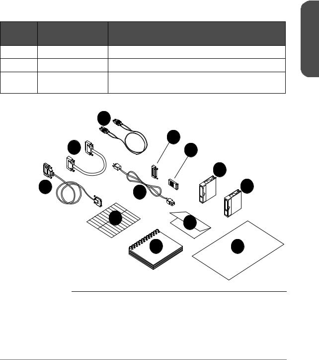
Table 1 |
Accessories |
|
|
|
Callout |
Component |
Description |
|
1Chapter |
Number |
|
|||
|
|
|||
|
|
|
|
|
11 |
Regulatory Insert |
Contains safety and regulatory information. |
|
|
12 |
Quick setup poster |
Overview of installation and configuration procedures. |
|
|
N/A |
Miscellaneous |
May include data sheets, upgrade information, product |
|
|
|
information |
information, and additional promotions. |
|
|
Figure 1 |
Accessories |
|
|
|
|
3 |
|
|
|
|
2 |
6 |
|
|
|
7 |
|
|
|
|
|
8 |
|
|
|
1 |
5 |
9 |
|
|
|
|
|
|
4 11
10 |
12 |
Note |
Your cables may look different from those in Figure 1. Cable |
|
types vary depending on library model. |
|
|
Chapter 1 |
Identifying Product Components 13 |

Choosing a Location
|
Choose a location that meets the criteria listed in Table 2. For additional |
|
|
specifications, refer to Technical Specifications on page 181. |
|
Table 2 |
Location Criteria |
|
|
|
|
Room temperature |
10-35º C (50-95º F) |
|
|
|
|
Power source |
■ AC power voltage: 100-127 V or 200-240 V |
|
|
■ Line frequency: 50-60 Hz |
|
|
■ A dedicated circuit is required. |
|
|
Caution: The AC power cord is the library’s main AC disconnect device and |
|
|
must be easily accessible at all times. |
|
|
|
|
LAN connection |
Locate the library near a LAN connection for connecting the RMC (remote |
|
|
management card). |
|
|
|
|
Library power |
2/20 series |
Max: 200W |
consumption |
4/40 series |
Max: 375W |
|
||
|
6/60 series |
Max: 560W |
|
8/80 series |
Max: 725W |
|
10/100 series |
Max: 1,200W |
|
|
|
Air quality |
Minimal sources of particulate contamination. Avoid areas near frequently used |
|
|
doors and walkways, stacks of supplies that collect dust, and smoke-filled rooms. |
|
|
Caution: Excessive dust and debris can damage tapes and tape drives. |
|
|
|
|
Humidity |
20-80% RH |
|
|
|
|
14 Choosing a Location |
Chapter 1 |

Table 2 |
Location Criteria |
|
|
|
|
Clearance |
2/20, 4/40, and 6/60 series stand-alone configurations — located on or |
|
|
below a table: |
|
|
Back: |
56 cm (22 in) for cooling and service. |
|
Front: |
86 cm (34 in) for operator access. |
|
Sides: |
56 cm (22 in) for removal of the external cover. |
|
|
|
|
2/20, 4/40, and 6/60 series rackmounted configurations: |
|
|
Back: |
61 cm (24 in) minimum to allow adequate room for service |
|
|
access. |
|
Front: |
86 cm (34 in) for operator access. |
|
Sides: |
56 cm (22 in) minimum |
|
Height: |
For ease of use and optimum safety, the top of the library |
|
|
should be mounted approximately 120 cm (48 in) above the |
|
|
floor. |
|
|
|
|
8/80 and 10/100 series tape libraries |
|
|
Back: |
56 cm (22 in) minimum |
|
Front: |
191 cm (75 in) minimum |
|
Sides: |
5 cm (2 in) minimum |
|
|
|
Floor rating |
For 8/80 and 10/100 series tape libraries only. |
|
|
A fully loaded library can weigh up to 325 kg (715 lbs). Each caster supports |
|
|
up to 96 kg (213 lbs). To support the weight exerted on the floor by the casters, |
|
|
the floor rating must meet or exceed 1,694 kg per square meter (347 lbs per |
|
|
square foot). |
|
|
|
|
Tip rating |
For 8/80 and 10/100 series libraries only. |
|
|
Do not tip the library more than 10°. Ensure that the location for the library has |
|
|
a level surface. |
|
|
|
|
1 Chapter
Chapter 1 |
Choosing a Location 15 |

Table 2 |
Location Criteria |
Rack location requirements
For 8/80 and 10/100 series libraries only.
Refer to the Rack Systems User’s Manual (included with the accessory kit or available at http://www.hp.com/racksolutions) for more information on installing the rack. This information includes: using the anti-tip mechanism, securing the rack to the floor, and weight/space requirements.
16 Choosing a Location |
Chapter 1 |

Installing the 2/20, 4/40 & 6/60 Series Libraries into a Rack
The instructions in this section apply to 2/20, 4/40, and 6/60 series libraries mounted in a standard 19-inch rack with a depth between 24 and 34 inches.
Caution Make sure that the rack and all equipment mounted in the rack have a reliable ground connection.
Verify that the total current of the rack components does not exceed the current rating of the power distribution unit or outlet receptacles.
WARNING Do not move the library without additional help or an appropriately rated lift device. The 2/20 series library weighs 40 kg (87 lb). The 4/40 series library weighs 75 kg (165 lb). The 6/60 series library weighs 104 kg (249 lb).
Tools and Parts
Before you begin, ensure that you have the following:
■Phillips #2 screwdriver
■Torx screwdriver with T20 and T25 bits
■1/2-inch open-end wrench
1 Chapter
Chapter 1 |
Installing the 2/20, 4/40 & 6/60 Series Libraries into a Rack 17 |
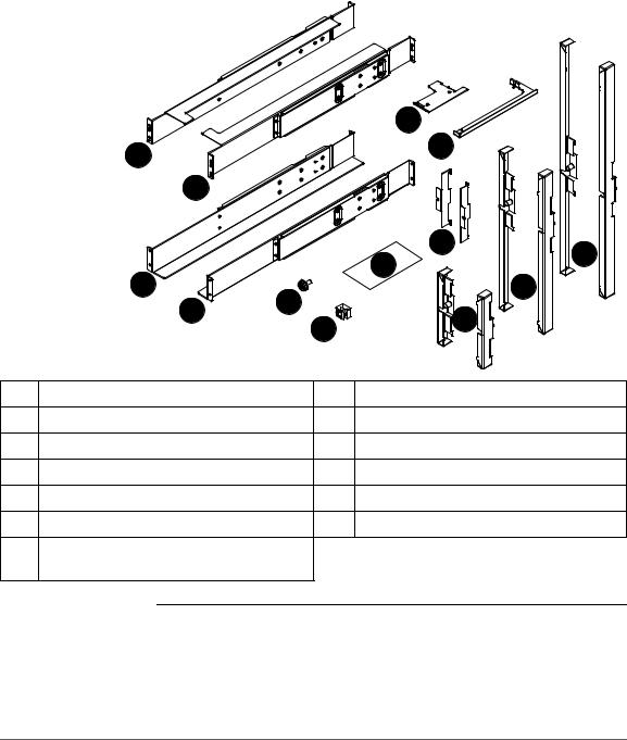
Figure 2 |
Rack Kit Parts |
|
|
|
|
9 |
|
|
1 |
|
|
10 |
|
|
|
|
|
|
|
|
|
2 |
|
|
|
|
|
|
|
8 |
13 |
|
|
|
|
7 |
|
|
3 |
|
|
|
|
|
|
5 |
12 |
|
|
|
|
4 |
11 |
|
|
|
|
6 |
|
||
|
|
|
|
||
|
|
|
|
|
|
1 |
Upper left rail (1) |
|
8 |
Flush-mount trim brackets (2) |
|
2 |
Upper right rail (1) |
|
9 |
2/20 series stop bracket (1) |
|
3 |
Lower left rail (1) |
|
10 4/40 and 6/60 series stop bracket (1) |
||
4 |
Lower right rail (1) |
|
11 2/20 series trim brackets (2) |
|
|
5 |
10-32 Screws (20) |
|
12 4/40 series trim brackets (2) |
|
|
6 |
10-32 Clip nuts (20) |
|
13 6/60 series trim brackets (2) |
|
|
7Clip nut template
(3 packaged together, one per model)
Note |
The rack kit includes extra trim brackets. The smaller flush-mount |
|
trim brackets are used with flush-mount racks. The larger trim |
|
brackets are typically used with older HP racks that have a |
|
55mm bezel depth. |
|
|
18 Installing the 2/20, 4/40 & 6/60 Series Libraries into a Rack |
Chapter 1 |
Rackmounting the Library
WARNING |
Before you begin, lower the rack’s leveler feet with the open- |
|
ended wrench, and extend the rack’s anti-tip foot. Failure to |
|
extend the anti-tip foot could result in personal injury or damage |
|
to the tape library if the rack tips over. |
|
|
|
|
Note |
For easiest access to the display panel and to the tape drawers, |
|
mount the top of the library in the middle of the rack or 120 cm |
|
(48 in) above the floor. |
|
|
1.Use the template for your model library as a guide, and install five clip nuts into each front column of the rack (Figure 3 on page 20, Figure 4 on page 20, or Figure 5 on page 21, depending on your library model). The upper grey clip nuts (item “a” below) are used for older HP racks (55-mm bezel depth). The lower grey clip nuts (item “b” below) are used for flushmount racks.
#
#
#
a #
#
#
#
b 


#
#
#
Use the template as a guide, and install four clip nuts into each back column of the rack.
Note |
Use the EIA markers as a reference point to ensure that the holes |
|
on the rack correspond to the holes on the template. The EIA |
|
markers on the template are represented by #>. Your rack might |
|
look different from the illustration. If the holes in the rack do not |
|
align with the template, move the template up one or two holes |
|
to create proper alignment. |
|
|
1 Chapter
Chapter 1 |
Installing the 2/20, 4/40 & 6/60 Series Libraries into a Rack 19 |
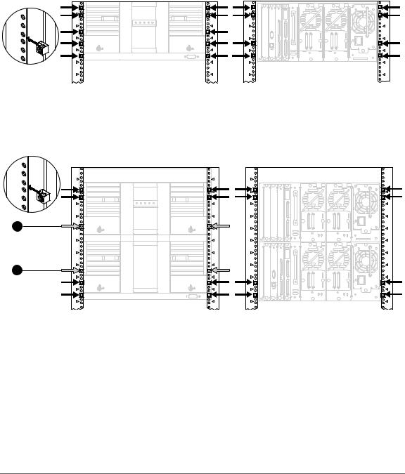
Figure 3
Figure 4
a
b
Clip Nut Placement (2/20 Series)
# |
# |
# |
# |
# |
# |
# |
# |
# |
# |
# |
# |
# |
# |
# |
# |
# |
# |
|
Front |
|
|
Clip Nut Placement (4/40 Series) |
|
# |
# |
# |
# |
# |
# |
# |
# |
# |
# |
# |
# |
# |
# |
# |
# |
# |
# |
# |
# |
# |
# |
# |
# |
# |
# |
# |
# |
# |
# |
# |
# |
# |
|
Front |
|
#
#
#
#
#
Back
 #
#
#
#
#
#
#
#
#
#
Back
20 Installing the 2/20, 4/40 & 6/60 Series Libraries into a Rack |
Chapter 1 |
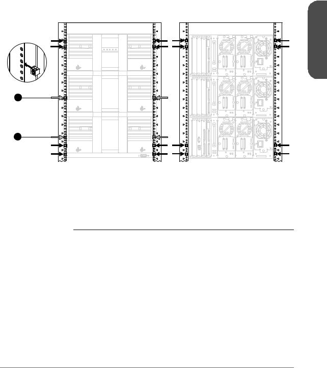
Figure 5
a
b
Clip Nut Placement (6/60 Series)
# |
# |
# |
# |
# |
# |
# |
|
# |
# |
# |
|
# |
# |
# |
# |
# |
# |
# |
# |
# |
# |
# |
# |
# |
# |
# |
# |
# |
# |
# |
# |
# |
# |
# |
# |
# |
# |
# |
# |
# |
# |
# |
# |
# |
# |
# |
# |
# |
# |
# |
# |
# |
# |
# |
# |
# |
# |
# |
# |
# |
# |
# |
# |
Front |
|
|
Back |
2.Align the upper (black) rail with the top two clip nuts and loosely install a screw into each clip nut. Slide the rail out so that it equals the rack depth, and attach to the back clip nuts. To allow for enough clearance, do not tighten these screws until you have installed the library.
Note |
Ensure that you are using the appropriate holes in the upper rail |
|
to allow enough clearance, illustrated in Figure 6 on page 22. |
|
The clearance between the top and bottom rails should be |
|
approximately: 2/20 series = 22 cm (9 in); 4/40 series = 43 cm |
|
(17 in); 6/60 series = 65 cm (26 in). |
|
|
1 Chapter
Chapter 1 |
Installing the 2/20, 4/40 & 6/60 Series Libraries into a Rack 21 |

3.Align the lower (black/silver) rail with the lower two clip nuts, and loosely install a screw into each clip nut. (See Figure 6.)
a.Slide the rail so that it equals the rack depth, and loosely install the screws.
b.Tighten all screws to secure the rails.
c.Tighten the two pre-installed screws inside each mounting rail to secure the rail in position.
Figure 6 |
Upper and Lower Rails |
20
40
60
22 Installing the 2/20, 4/40 & 6/60 Series Libraries into a Rack |
Chapter 1 |
4. Install the library.
WARNING The majority of the weight is near the back of the library. Use appropriate force when lifting the library, while ensuring the library remains level to avoid overturning.
Note |
To reduce the weight of the library, you can easily remove all the |
|
drives. See Removing and Replacing Drive Modules on |
|
page 162 for more information. |
|
|
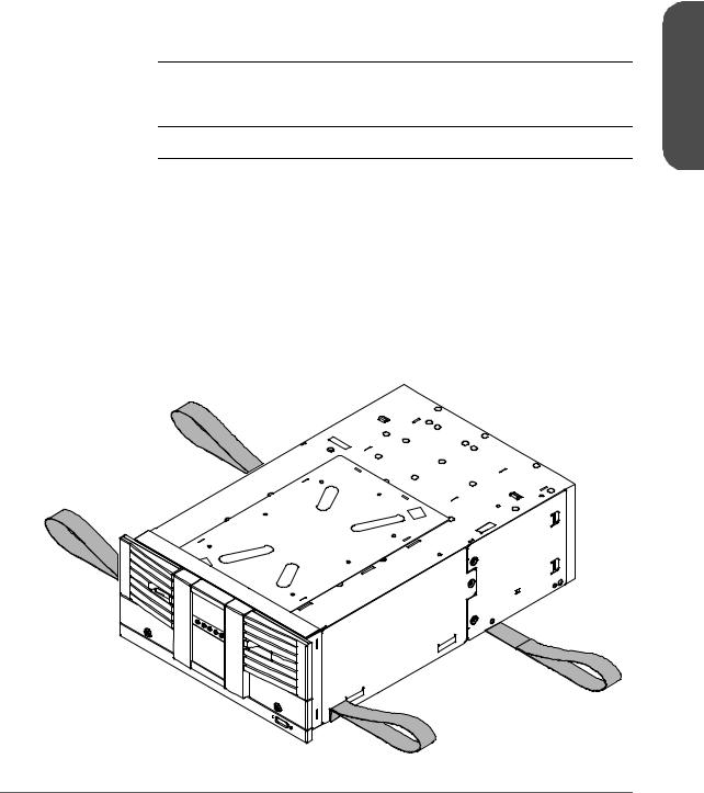
2/20 Series Library:
With the help of another person, use the lifting straps built into the sides of the library, and slide the library between the upper and lower sets of mounting rails. Remove the lifting straps once the library is partially installed. Save these straps for future use when moving the library.
Figure 7 |
Lifting Straps |
1 Chapter
Chapter 1 |
Installing the 2/20, 4/40 & 6/60 Series Libraries into a Rack 23 |

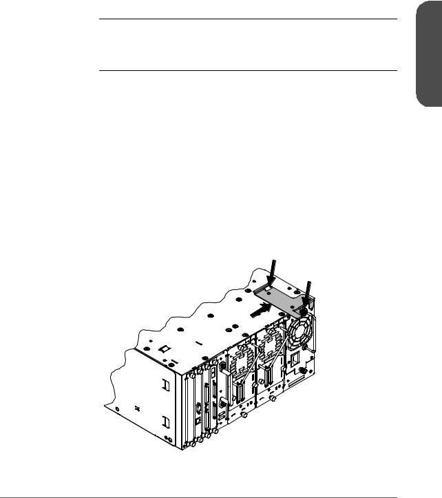
4/40 and 6/60 Series Libraries:
Use a mechanical lift that is rated to the weight of the library, and follow the steps below to install the library.
a.Break away the edges of the packing material at the bottom of the library.
b.Use the straps to ease the library onto an appropriately rated mechanical lift. Use the lift to raise the library so that it aligns with the bottom rails.
c.Slide the library onto the lower rails. Have at least one person guide the library from the front and one person pull the library from the back, using the vertical handle (Figure 8 on page 24).
d.Remove the lifting straps once the library is partially installed. Save the straps for future use when moving the library.
Figure 8 |
Library Installation |
Caution Do not push the library from the front. Use the handle shown in Figure 8. DO NOT pull on the handle(s) located on the back of the power supply or drive modules.
24 Installing the 2/20, 4/40 & 6/60 Series Libraries into a Rack |
Chapter 1 |
WARNING Do not move the library without additional help or an appropriately rated lift device. The 2/20 series library weighs 40 kg (87 lb). The 4/40 series library weighs 75 kg (165 lb). The 6/60 series library weighs 104 kg (249 lb).
5.Tighten the screws on the top mounting rail to secure the library.
6.Install the stop bracket to ensure the library is secured inside the rack, and will not come out past the service position (approximately 2/3 of the library is out of the rack).
2/20 Series Library:
a.From the back of the library, unscrew the power supply thumbscrew by hand or with a screwdriver.
b.Install the stop bracket by sliding the edge of the bracket under the thumbscrew and threading the tab through the latch stop.
c.Tighten the power supply thumbscrew to secure the bracket to the library.
Figure 9 |
Installing the Stop Bracket for the 2/20 Series Library |
1 Chapter
Chapter 1 |
Installing the 2/20, 4/40 & 6/60 Series Libraries into a Rack 25 |
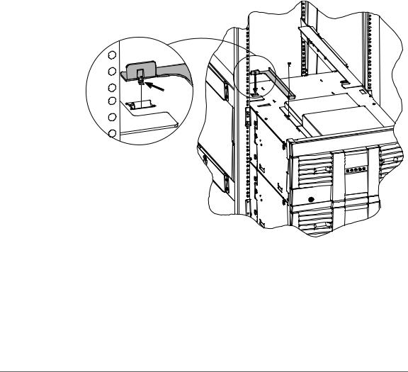
4/40 and 6/60 Series Libraries:
a.Ensure access to the top of the library. If necessary, push the library to the service position to access the top cover. Do not push the library past the latch stop tabs.
b.Remove the left back screw from the top cover.
c.Install the stop bracket by inserting the tab into the latch stop.
d.Re-install the screw into the top cover.
Figure 10 |
Installing the Stop Bracket for 4/40 and 6/60 Series Libraries |
26 Installing the 2/20, 4/40 & 6/60 Series Libraries into a Rack |
Chapter 1 |
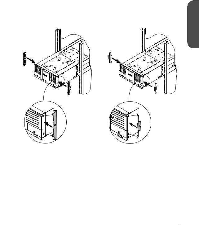
7.Insert trim brackets into the slots on each side of the library (Figure 11 through Figure 13).
Figure 11 |
Trim Brackets (2/20 Series) |
1 Chapter
(larger trim brackets) |
(flush-mount trim brackets) |
||
|
|
|
|
|
Note |
The rack kit includes extra trim brackets. The smaller flush-mount |
|
|
|
trim brackets are used with flush-mount racks. The larger trim |
|
|
|
brackets are typically used with older HP racks that have a |
|
|
|
55mm bezel depth. |
|
|
|
|
|
Chapter 1 |
Installing the 2/20, 4/40 & 6/60 Series Libraries into a Rack 27 |

Figure 12 |
Trim Brackets (4/40 Series) |
(larger trim brackets) |
(flush-mount trim brackets) |
|
|
|
|
|
Note |
The rack kit includes extra trim brackets. The smaller flush-mount |
|
|
trim brackets are used with flush-mount racks. The larger trim |
|
|
brackets are typically used with older HP racks that have a |
|
|
55mm bezel depth. |
|
|
|
28 Installing the 2/20, 4/40 & 6/60 Series Libraries into a Rack |
Chapter 1 |
 Loading...