

Page 1
TNC 410
TNC 426
TNC 430
NC Software
286 060-xx
286 080-xx
280 472-xx
280 473-xx
280 474-xx
280 475-xx
User's Manual
ISO Programming
4/99
Page 2
Controls on the visual display unit
Split screen layout
Switch between machining or
programming modes
Soft keys for selecting functions
in screen
Switching the soft-key rows
Changing the screen settings
Controls on the TNC
(only BC 120)
Typewriter keyboard for entering letters and
symbols
Q
W E
G
F S T M
R
T
Y
Comments
ISO programs
File name
Machine operating modes
Manual Operation
Electronic Handwheel
Positioning with Manual Data Input (MDI)
Program Run, Single Block
Program Run, Full Sequence
Programming modes
Programming and Editing
Test run
Program/file management, TNC functions
Select or delete programs and files
PGM
MGT
External data transfer
PGM
Enter program call in a program
CALL
MOD
MOD functions
HELP
Displaying help texts for NC error messages
CALC
Pocket calculator
Moving the cursor, going directly to blocks, cycles
and parameter functions
Move highlight
GOTO
Go directly to blocks, cycles and parameter
functions
Override control knobs for feed rate/spindle speed
100
1
50
50
F %
0
100
1
50
50
S %
0
Programming path movements
(only conversational)
APPR
Approach/depart contour
DEP
FK free contour programming
L
Straight line
CC
Circle center/pole for polar coordinates
C
Circle with center
CR
Circle with radius
CT
Circular arc with tangential connection
CHF
Chamfer
RND
Corner rounding
Tool data (only conversational)
TOOL
DEF
Entering and calling tool length and
TOOL
CALL
radius
Cycles, subprograms, and program section
repeats (only conversational)
CYCL
CYCL
DEF
LBL
SET
Define and call cycles
CALL
LBL
Enter and call labels for
CALL
subprogramming and program
section repeats
STOP
Program stop in a program
TOUCH
Enter touch probe functions in a program
PROBE
Coordinate axes and numbers, editing
...
X
...
0
Select coordinate axes or enter
V
them in a program
Numbers
9
Decimal point
/
+
Change arithmetic sign
Polar coordinates
P
Incremental dimensions
Q parameters
Q
Capture actual position
NO
Skip dialog questions, delete words
ENT
ENT
END
Clear numerical entry or TNC error message
CE
DEL
Confirm entry and resume
dialog
End block
Abort dialog, delete program section
Page 3
Page 4

Page 5
TNC Models, Software and
Features
This manual describes functions and features provided by
the TNCs with the following NC software numbers.
TNC Model NC Software No.
TNC 410 286 060-xx
TNC 410 286 080-xx
TNC 426 CB, TNC 426 PB 280 472-xx
TNC 426 CF, TNC 426 PF 280 473-xx
TNC 430 CA, TNC 430 PA 280 472-xx
TNC 430 CE, TNC 430 PE 280 473-xx
TNC 426 CB, TNC 426 PB 280 474-xx
TNC 426 CF, TNC 426 PF 280 475-xx
TNC 426 M 280 474-xx
TNC 426 ME 280 475-xx
TNC 430 CA, TNC 430 PA 280 474-xx
TNC 430 CE, TNC 430 PE 280 475-xx
TNC 430 M 280 474-xx
TNC 430 ME 280 475-xx
The suffixes E and F indicate the export versions of the TNC
which have the following limitations:
■ Linear movement is possible in no more than 4 axes
simultaneously
The machine tool builder adapts the useable features of the
TNC to his machine by setting machine parameters. Some
of the functions described in this manual may not be
among the features provided by your machine tool.
TNC functions that may not be available on your machine
include:
■ Probing function for the 3-D touch probe
■ Digitizing option (conversational programming only)
■ Tool measurement with the TT 120 (conversational
programming only)
■ Rigid tapping
■ Returning to the contour after an interruption
Please contact your machine tool builder to become familiar
with the individual implementation of the control on your
machine.
Many machine manufacturers, as well as HEIDENHAIN,
offer programming courses for the TNCs. We recommend
these courses as an effective way of improving your
programming skill and sharing information and ideas with
other TNC users.
Touch Probe Cycles User's Manual:
In addition to this manual, another manual is
available describing all the touch probe functions
of the TNC 426 / TNC 430. Please contact
HEIDENHAIN if you require a copy of this User's
Manual. ID number: 329 203-xx.
Location of use
The TNC complies with the limits for a Class A device in
accordance with the specifications in EN 55022, and is
intended for use primarily in industrially-zoned areas.
Contents
IHEIDENHAIN TNC 410, TNC 426, TNC 430
Page 6

Page 7

Contents
Introduction
1
Manual Operation and Setup
Positioning with Manual Data Input (MDI)
Programming: Fundamentals of NC,
File Management, Programming Aids
Programming: Tools
Programming: Programming Contours
Programming: Miscellaneous Functions
Programming: Cycles
Programming: Subprograms and Program
Section Repeats
Programming: Q Parameters
Test Run and Program Run
3-D Touch Probes
2
Contents
3
4
5
6
7
8
9
10
11
12
MOD Functions
Tables and Overviews
13
14
IIIHEIDENHAIN TNC 410, TNC 426, TNC 430
Page 8

1 INTRODUCTION ..... 1
1.1 The TNC 410, The TNC 426, and The TNC 430 ..... 2
1.2 Visual Display Unit and Keyboard ..... 3
Contents
1.3 Modes of Operation ..... 5
1.4 Status Displays ..... 9
1.5 Accessories: HEIDENHAIN 3-D Touch Probes and Electronic Handwheels ..... 14
2 MANUAL OPERATION AND SETUP ..... 15
2.1 Switch-on, Switch-off ..... 16
2.2 Moving the Machine Axes ..... 17
2.3 Spindle Speed S, Feed Rate F and Miscellaneous Functions M ..... 19
2.4 Datum Setting (Without a 3-D Touch Probe) ..... 20
2.5 Tilt the working plane (not TNC 410) ..... 21
3 POSITIONING WITH MANUAL DATA INPUT (MDI) ..... 25
3.1 Program and Run Simple Machining Operations ..... 26
4 PROGRAMMING: FUNDAMENTALS OF NC, FILE MANAGEMENT,
PROGRAMMING AIDS, PALLET MANAGEMENT ..... 31
4.1 Fundamentals of NC ..... 32
4.2 File Management: Fundamentals ..... 37
4.3 Standard file management TNC 426, TNC 430 ..... 38
4.4 Expanded File Management TNC 426, TNC 430 ..... 43
4.5 File Management for the TNC 410 ..... 56
4.6 Creating and Writing Programs ..... 59
4.7 Programming Graphics (not TNC 426, TNC 430) ..... 66
4.8 Adding Comments ..... 68
4.9 Creating Text Files (not TNC 410) ..... 69
4.10 The Pocket Calculator (not TNC 410) ..... 72
4.11 Direct Help for NC Error Messages (not TNC 410) ..... 73
4.12 Help Function (not TNC 426, TNC 430) ..... 74
4.13 Pallet Management (not TNC 410) ..... 75
IV
Contents
Page 9

5 PROGRAMMING: TOOLS ..... 77
5.1 Entering Tool-Related Data ..... 78
5.2 Tool Data ..... 79
5.3 Tool Compensation ..... 90
6 PROGRAMMING: PROGRAMMING CONTOURS ..... 95
6.1 Overview of Tool Movements ..... 96
6.2 Fundamentals of Path Functions ..... 97
6.3 Contour Approach and Departure ..... 99
6.4 Path Contours — Cartesian Coordinates ..... 102
Overview of path functions ..... 102
Straight line at rapid traverse G00, Straight line with feed rate G01 F . . . ..... 103
Inserting a chamfer between two straight lines ..... 103
Circle center I, J ..... 104
Circular path G02/G03/G05 around the circle center I, J ..... 104
Circular path G02/G03/G05 with defined radius ..... 105
Rounding corners G25 ..... 108
Example: Linear movements and chamfers with Cartesian coordinates ..... 109
Example: Circular movements with Cartesian coordinates ..... 110
Example: Full circle with Cartesian coordinates ..... 111
6.5 Path Contours—Polar Coordinates ..... 112
Zero point for polar coordinates: pole I, J ..... 112
Straight line at rapid traverse G10, Straight line with feed rate G11 F . . . ..... 113
Circular path G12/G13/G15 around pole I, J ..... 113
Circular path G16 with tangential approach ..... 114
Helical interpolation ..... 114
Example: Linear movement with polar coordinates ..... 116
Example: Helix ..... 117
Contents
VHEIDENHAIN TNC 410, TNC 426, TNC 430
Page 10

7 PROGRAMMING: MISCELLANEOUS FUNCTIONS ..... 119
7.1 Entering Miscellaneous Functions M ..... 120
7.2 Miscellaneous Functions for Program Run Control, Spindle and Coolant ..... 121
Contents
7.3 Miscellaneous Functions for Coordinate Data ..... 121
7.4 Miscellaneous Functions for Contouring Behavior ..... 124
Smoothing corners: M90 ..... 124
Entering contour transitions between two contour elements: M112 (not TNC 426, TNC 430) ..... 125
Contour filter: M124 (not TNC 426, TNC 430) ..... 127
Machining small contour steps: M97 ..... 129
Machining open contours: M98 ..... 130
Feed rate factor for plunging movements: M103 ..... 131
Feed rate in micrometers per spindle revolution: M136
(only TNC 426, TNC 430 with NC software 280 474-xx) ..... 131
Feed rate at circular arcs: M109/M110/M111 ..... 132
Calculating the radius-compensated path in advance (LOOK AHEAD): M120 ..... 132
Superimposing handwheel positioning during program run: M118 (not TNC 410) ..... 133
7.5 Miscellaneous Functions for Rotary Axes ..... 134
Feed rate in mm/min on rotary axes A, B, C: M116 (not TNC 410) ..... 134
Shorter-path traverse of rotary axes: M126 ..... 134
Reducing display of a rotary axis to a value less than 360°: M94 ..... 135
Automatic compensation of machine geometry when working with tilted axes: M114
(not TNC 410) ..... 136
Maintaining the position of the tool tip when positioning with tilted axes (TCPM*): M128 ..... 137
Exact stop at corners with nontangential transitions: M134 ..... 139
Selection of tilting axes: M138 (only TNC 426, TNC 430 with NC software 280 474-xx) ..... 139
7.6 Miscellaneous Functions for Laser Cutting Machines (not TNC 410) ..... 140
VI
Contents
Page 11

8 PROGRAMMING: CYCLES ..... 141
8.1 General Information on Cycles ..... 142
8.2 Point Tables (only TNC 410) ..... 144
Creating a point table ..... 144
Selecting point tables in the program ..... 144
Calling a cycle in connection with point tables ..... 145
8.3 Drilling Cycles ..... 146
PECKING (Cycle G83) ..... 146
DRILLING (Cycle G200) ..... 148
REAMING (Cycle G201) ..... 149
BORING (Cycle G202) ..... 150
UNIVERSAL DRILLING (Cycle G203) ..... 151
BACK BORING (Cycle G204) ..... 153
UNIVERSAL PECKING (Cycle G205, only with the TNC 426, TNC 430 with NC software 280 474-xx) ..... 155
BORE MILLING (Cycle G208, only with the TNC 426, TNC 430 with NC software 280 474-xx) ..... 157
TAPPING with a floating tap holder (Cycle G84) ..... 159
TAPPING NEW with floating tap holder (Cycle G206, only with TNC 426, TNC 430
with NC software 280 474-xx) ..... 160
RIGID TAPPING (Cycle G85) ..... 162
RIGID TAPPING NEW(Cycle G207, only with the TNC 426, TNC 430 with NC software 280 474-xx) ..... 163
THREAD CUTTING (Cycle G86, not TNC 410) ..... 165
Example: Drilling cycles ..... 166
Example: Drilling cycles ..... 167
Example: Calling drilling cycles in connection with point tables (only with TNC 410) ..... 168
8.4 Cycles for milling pockets, studs and slots ..... 170
POCKET MILLING (Cycles G75, G76) ..... 171
POCKET FINISHING (Cycle G212) ..... 172
STUD FINISHING (Cycle G213) ..... 174
CIRCULAR POCKET MILLING (Cycles G77, G78) ..... 175
CIRCULAR POCKET FINISHING (Cycle G214) ..... 177
CIRCULAR STUD FINISHING (Cycle G215) ..... 178
SLOT MILLING (Cycle G74) ..... 180
SLOT with reciprocating plunge-cut (Cycle G210) ..... 181
CIRCULAR SLOT with reciprocating plunge-cut (Cycle G211) ..... 183
Example: Milling pockets, studs and slots ..... 185
Contents
VIIHEIDENHAIN TNC 410, TNC 426, TNC 430
Page 12

8.5 Cycles for Machining Hole Patterns ..... 186
Contents
8.6 SL Cycles Group I ..... 191
8.7 SL Cycles Group II (not TNC 410) ..... 197
8.8 Cycles for Face Milling ..... 216
CIRCULAR PATTERN (Cycle 220) ..... 187
LINEAR PATTERN (Cycle 221) ..... 188
Example: Circular hole patterns ..... 191
CONTOUR GEOMETRY (Cycle G37) ..... 192
PILOT DRILLING (Cycle G56) ..... 193
ROUGH-OUT (Cycle G57) ..... 194
CONTOUR MILLING (Cycle G58/G59) ..... 196
CONTOUR GEOMETRY (Cycle G37) ..... 199
Overlapping contours ..... 199
CONTOUR DATA (Cycle G120) ..... 201
PILOT DRILLING (Cycle G121) ..... 202
ROUGH-OUT (Cycle G122) ..... 203
FLOOR FINISHING (Cycle G123) ..... 204
SIDE FINISHING (Cycle G124) ..... 205
CONTOUR TRAIN (Cycle G125) ..... 206
CYLINDER SURFACE (Cycle G127) ..... 208
CYLINDER SURFACE slot milling (Cycle G128, only in TNC 426, TNC 430 with
NC software 280 474-xx) ..... 210
Example: Pilot drilling, roughing-out and finishing overlapping contours ..... 212
Example: Cylinder surface ..... 214
Example: Contour train ..... 215
RUN DIGITIZED DATA (Cycle G60, not TNC 410) ..... 216
MULTIPASS MILLING (Cycle G230) ..... 218
RULED SURFACE (Cycle 231) ..... 220
Example: Multipass milling ..... 222
VIII
Contents
Page 13

8.9 Coordinate transformation cycles ..... 223
DATUM SHIFT (Cycle G54) ..... 224
DATUM SHIFT with datum tables (Cycle G53) ..... 225
MIRROR IMAGE (Cycle G28) ..... 228
ROTATION (Cycle G73) ..... 229
SCALING FACTOR (Cycle G72) ..... 230
WORKING PLANE (Cycle G80, not TNC 410) ..... 231
Example: Coordinate transformation cycles ..... 236
8.10 Special Cycles ..... 238
DWELL TIME (Cycle G04) ..... 238
PROGRAM CALL (Cycle G39) ..... 238
ORIENTED SPINDLE STOP (Cycle G36) ..... 239
TOLERANCE (Cycle G62, not TNC 410) ..... 240
9 PROGRAMMING: SUBPROGRAMS AND PROGRAM SECTION REPEATS ..... 241
9.1 Marking Subprograms and Program Section Repeats ..... 242
9.2 Subprograms ..... 242
9.3 Program Section Repeats ..... 243
9.4 Program as Subprogram ..... 244
9.5 Nesting ..... 245
9.6 Programming Examples ..... 248
Example: Milling a contour in several infeeds ..... 248
Example: Groups of holes ..... 249
Example: Groups of holes with several tools ..... 250
Contents
10 PROGRAMMING: Q PARAMETERS ..... 253
10.1 Principle and Overview ..... 254
10.2 Part Families — Q Parameters in Place of Numerical Values ..... 255
10.3 Describing Contours Through Mathematical Functions ..... 256
10.4 Trigonometric Functions ..... 258
10.5 If-Then Decisions with Q Parameters ..... 259
10.6 Checking and Changing Q Parameters ..... 260
10.7 Additional Functions ..... 261
10.8 Entering Formulas Directly ..... 263
10.9 Preassigned Q Parameters ..... 266
10.10 Programming Examples ..... 269
Example: Ellipse ..... 269
Example: Concave cylinder machined with spherical cutter ..... 271
Example: Convex sphere machined with end mill ..... 273
IXHEIDENHAIN TNC 410, TNC 426, TNC 430
Page 14

11 TEST RUN AND PROGRAM RUN ..... 275
11.1 Graphics ..... 276
11.2 Functions for Program Display in Program Run and Test Run ..... 281
Contents
11.3 Test run ..... 282
11.4 Program Run ..... 284
11.5 Blockwise Transfer: Running Long Programs (not with TNC 426, TNC 430) ..... 292
11.6 Optional block skip ..... 293
11.7 Optional Program Run Interruption (not TNC 426, TNC 430) ..... 293
12 3-D TOUCH PROBES ..... 295
12.1 Touch Probe Cycles in the Manual and Electronic Handwheel ..... 296
12.2 Setting the Datum with a 3-D Touch Probe ..... 304
12.3 Measuring Workpieces with a 3-D Touch Probe ..... 307
13 MOD FUNCTIONS ..... 313
13.1 Selecting, Changing and Exiting the MOD Functions ..... 314
13.2 System Information (not TNC 426, TNC 430) ..... 315
13.3 Software Numbers and Option Numbers TNC 426, TNC 430 ..... 316
13.4 Code Number ..... 316
13.5 Setting the Data Interface for the TNC 410 ..... 317
Setting the OPERATING MODE of the external device ..... 317
Setting the BAUD RATE ..... 317
13.6 Setting Up the Data Interfaces for TNC 426, TNC 430 ..... 318
13.7 Software for Data Transfer ..... 320
13.8 Ethernet Interface (only TNC 426, TNC 430) ..... 322
13.9 Configuring PGM MGT (not TNC 410) ..... 329
13.10 Machine-Specific User Parameters ..... 329
13.11 Showing the Workpiece in the Working Space (not TNC 410) ..... 329
13.12 Position Display Types ..... 331
13.13 Unit of Measurement ..... 331
13.14 Programming Language for MDI ..... 332
13.15 Selecting the Axes for Generating L Blocks (not TNC 410, only Conversational Dialog) ..... 332
13.16 Axis Traverse Limits, Datum Display ..... 332
13.17 The HELP Function ..... 334
13.18 Operating Time (via Code Number for TNC 410) ..... 334
X
Contents
Page 15

TABLES AND OVERVIEWS ..... 335
14.1 General User Parameters ..... 336
14.2 Pin Layout and Connecting Cable for the Data Interfaces ..... 352
14.3 Technical Information ..... 356
14.4 Exchanging the Buffer Battery ..... 360
14.5 Addresses (ISO) ..... 360
Contents
XIHEIDENHAIN TNC 410, TNC 426, TNC 430
Page 16

Page 17
Introduction
1
Page 18
1.1 The TNC 410, The TNC 426, and
The TNC 430
HEIDENHAIN TNC controls are workshop-oriented contouring
controls that enable you to program conventional machining
operations right at the machine in an easy-to-use conversational
programming language. They are designed for milling, drilling and
boring machines, as well as for machining centers. The TNC 410 can
control up to 4 axes, the TNC 426 up to 5 axes, and the TNC 430 up
to 9 axes. You can also change the angular position of the spindle
under program control.
Keyboard and screen layout are clearly arranged in a such way that
the functions are fast and easy to use.
Programming: HEIDENHAIN conversational and ISO formats
HEIDENHAIN conversational programming is an especially easy
method of writing programs. Interactive graphics illustrate the
individual machining steps for programming the contour. If a
production drawing is not dimensioned for NC, the HEIDENHAIN
FK free contour programming carries out the necessary calculations
automatically. Workpiece machining can be graphically simulated
either during or before actual machining. It is also possible to
program in ISO format or DNC mode.
You can enter a program while the control is running another. With
the TNC 426, TNC 430 it is also possible to test one program while
another is being run.
1.1 The TNC 410, the TNC 426, the TNC 430
Compatibility
The TNC can execute all part programs that were written on
HEIDENHAIN controls TNC 150 B and later.
2
1 Introduction
Page 19
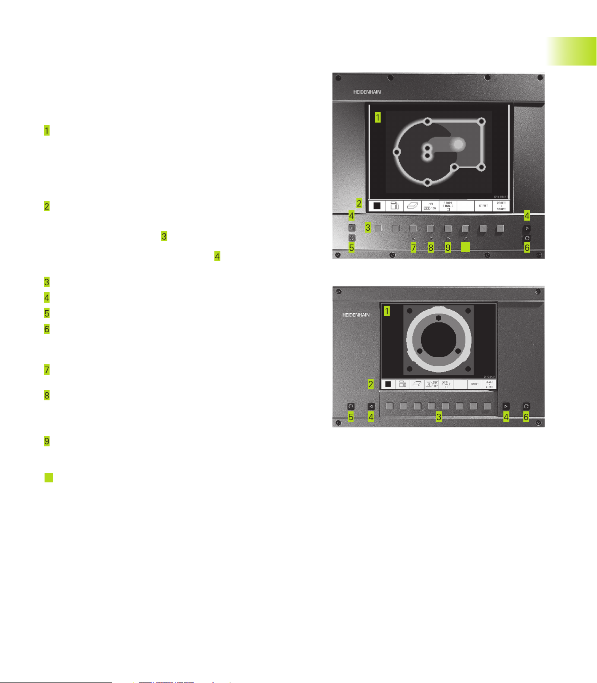
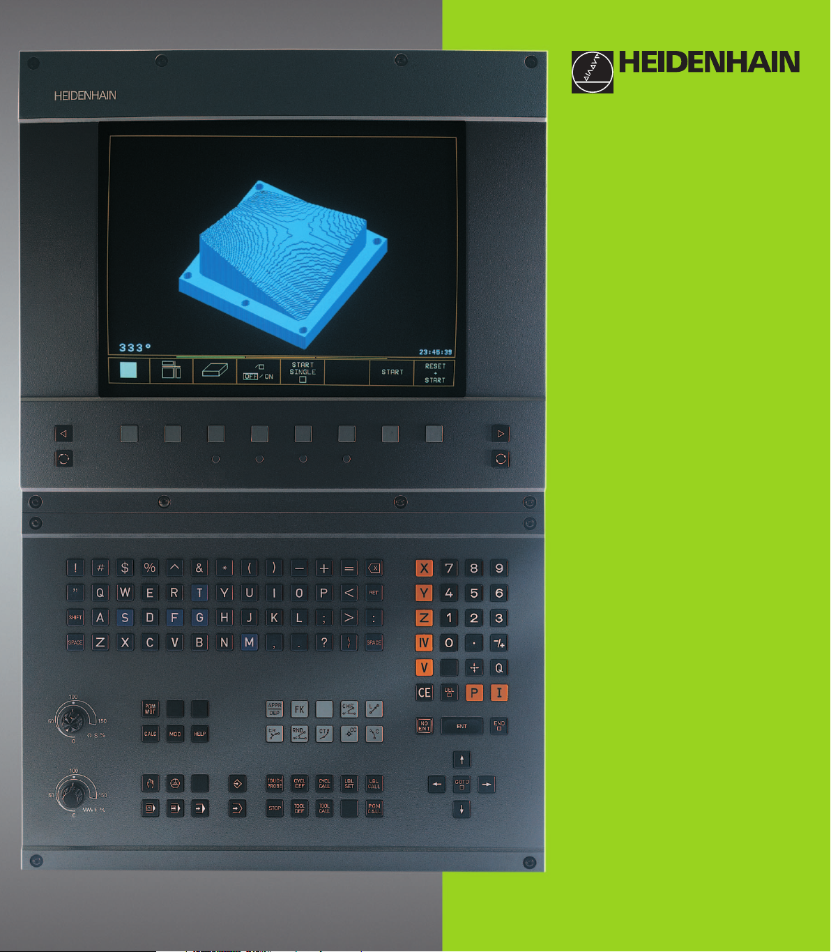
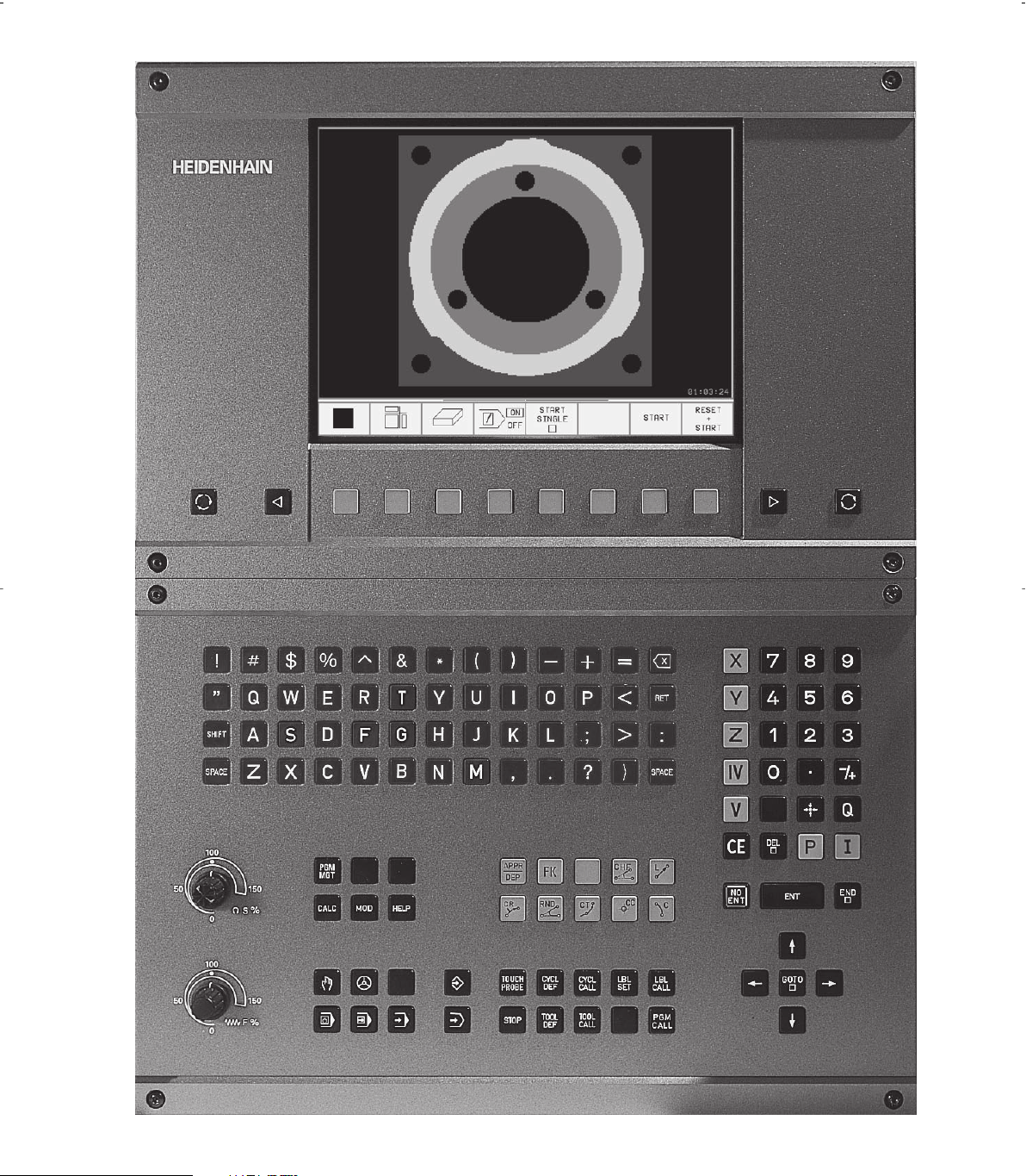
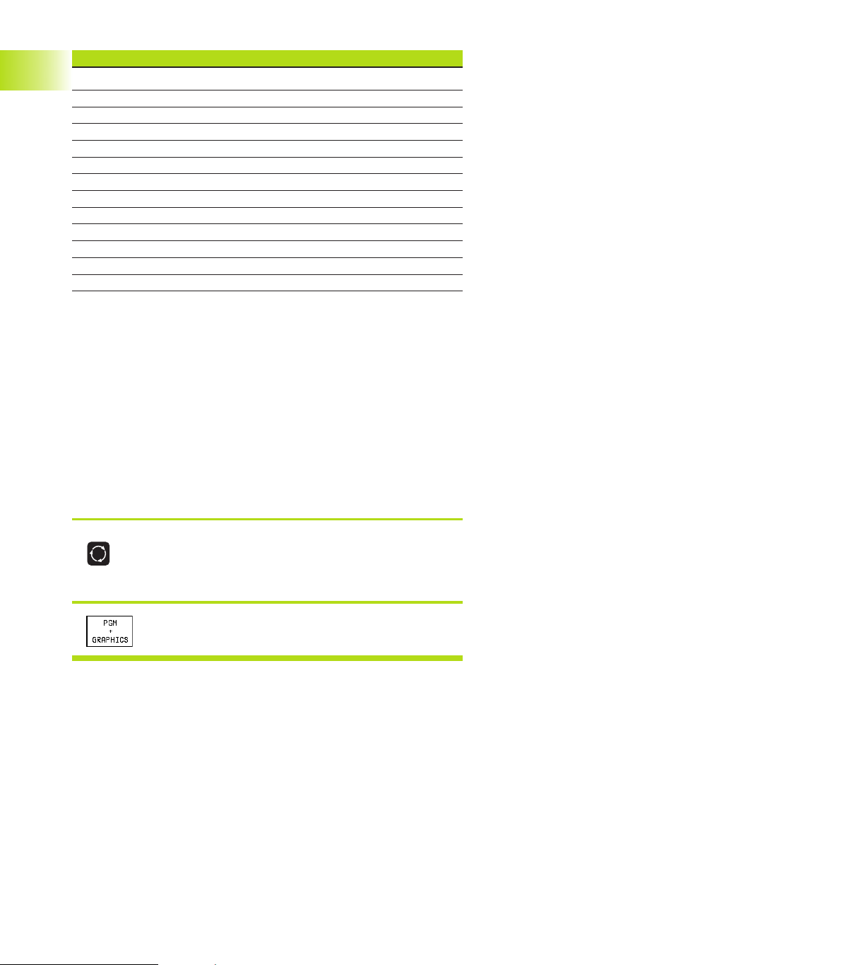
1.2 Visual Display Unit and Keyboard
Visual display unit
The TNC is available with either a color CRT screen (BC 120) or a
TFT flat panel display (BF 120. The figures at right show the keys
and controls on the BC 120 (upper right) and the BF 120 (middle
right).
Header
When the TNC is on, the selected operating modes are shown
in the screen header. With the TNC 426, TNC 430, the machine
operating modes are on the left and the programming modes
are on the right. The currently active mode is displayed in the
larger box, where the dialog prompts and TNC messages also
appear (unless the TNC is showing only graphics).
Soft keys
In the footer the TNC indicates additional functions in a soft-key
row. You can select these functions by pressing the keys
immediately below them
soft-key row indicate the number of soft-key rows that can be
called with the black arrow keys to the
The line representing the active soft-key row is highlighted.
Soft key selector keys
Switching the soft-key rows
Setting the screen layout
Shift key for switchover between machining and programming
modes
. The lines immediately above the
outside right and left.
10
1.2 Visual Display Unit and Keyboard
Keys on BC 120 only
Screen demagnetization;
Exit main menu for screen settings
Select main menu for screen settings;
In the main menu: Move highlight downward
In the submenu: Reduce value
In the main menu: Move highlight upward
In the submenu: Increase value
In the main menu: Select submenu
10
In the submenu: Exit submenu
See next page for the screen settings.
Move picture to the left or downward
Move picture to the right or upward
3HEIDENHAIN TNC 410, TNC 426, TNC 430
Page 20
Main menu dialog Function
BRIGHTNESS Adjust brightness
CONTRAST Adjust contrast
H-POSITION Adjust horizontal position
H-SIZE Adjust picture width
V-POSITION Adjust vertical position
V-SIZE Adjust picture height
SIDE-PIN Correct barrel-shaped distortion
TRAPEZOID Correct trapezoidal distortion
ROTATION Correct tilting
COLOR TEMP Adjust color temperature
R-GAIN Adjust strength of red color
B-GAIN Adjust strength of blue color
RECALL No function
The BC 120 is sensitive to magnetic and electromagnetic noise,
which can distort the position and geometry of the picture.
Alternating fields can cause the picture to shift periodically or to
become distorted.
Screen layout
1.2 Visual Display Unit and Keyboard
You select the screen layout yourself: In the Programming and
Editing mode of operation, for example, you can have the TNC
show program blocks in the left window while the right window
displays programming graphics (only TNC 410). The available screen
windows depend on the selected operating mode.
To change the screen layout:
Press the switch-over key: The soft-key row
shows the available layout options (see section
1.3 ”Modes of Operation”).
<
Select the desired screen layout.
4
1 Introduction
Page 21
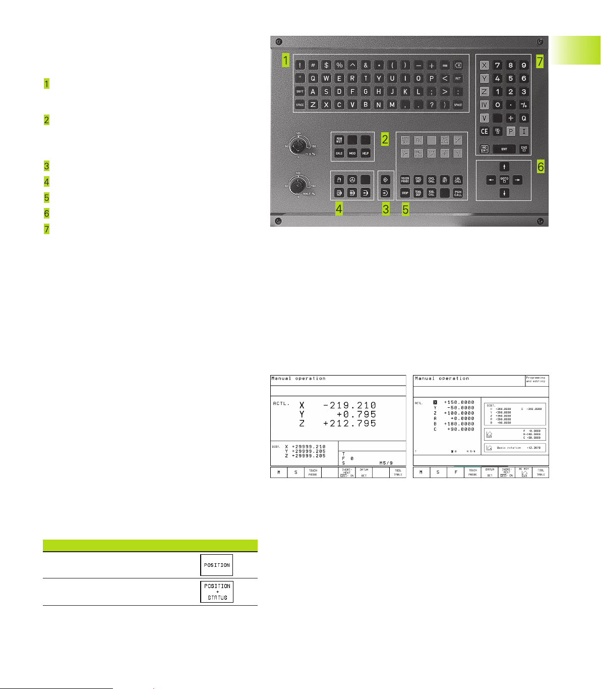
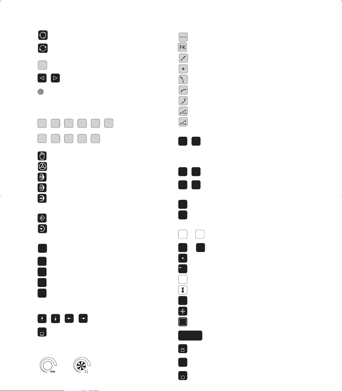
Keyboard
The figure at right shows the keys of the keyboard
grouped according to their functions:
Alphanumeric keyboard
for entering texts and file names, as well as for
programming in ISO format
File management,
pocket calculator (not TNC 410),
MOD function,
HELP function
Programming modes
Machine operating modes
Initiation of programming dialog
Arrow keys and GOTO jump command
Numerical input and axis selection
The functions of the individual keys are described
on the inside front cover. Machine panel buttons,
e.g. NC START, are described in the manual for your
machine tool.
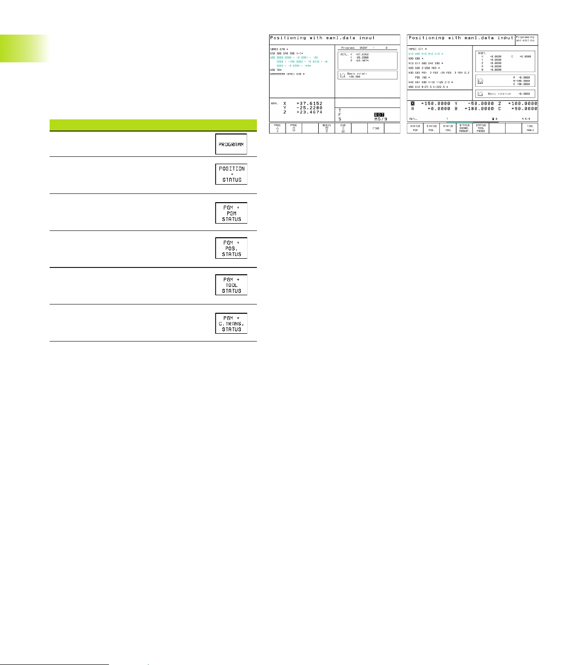
1.3 Modes of Operation
The TNC offers the following modes of operation
for the various functions and working steps that you
need to machine a workpiece:
1.3 Modes of Operation
Manual Operation and Electronic
Handwheel
The Manual Operation mode is required for setting
up the machine tool. In this operating mode, you
can position the machine axes manually or by
increments, set the datums, and tilt the working
plane.
The Electronic Handwheel mode of operation
allows you to move the machine axes manually with
the HR electronic handwheel.
Soft keys for selecting the screen layout
(select as describe above, TNC 410: see screen
layout with program run, full sequence)
Screen windows Soft key
Positions
Left: positions. Right: status display.
5HEIDENHAIN TNC 410, TNC 426, TNC 430
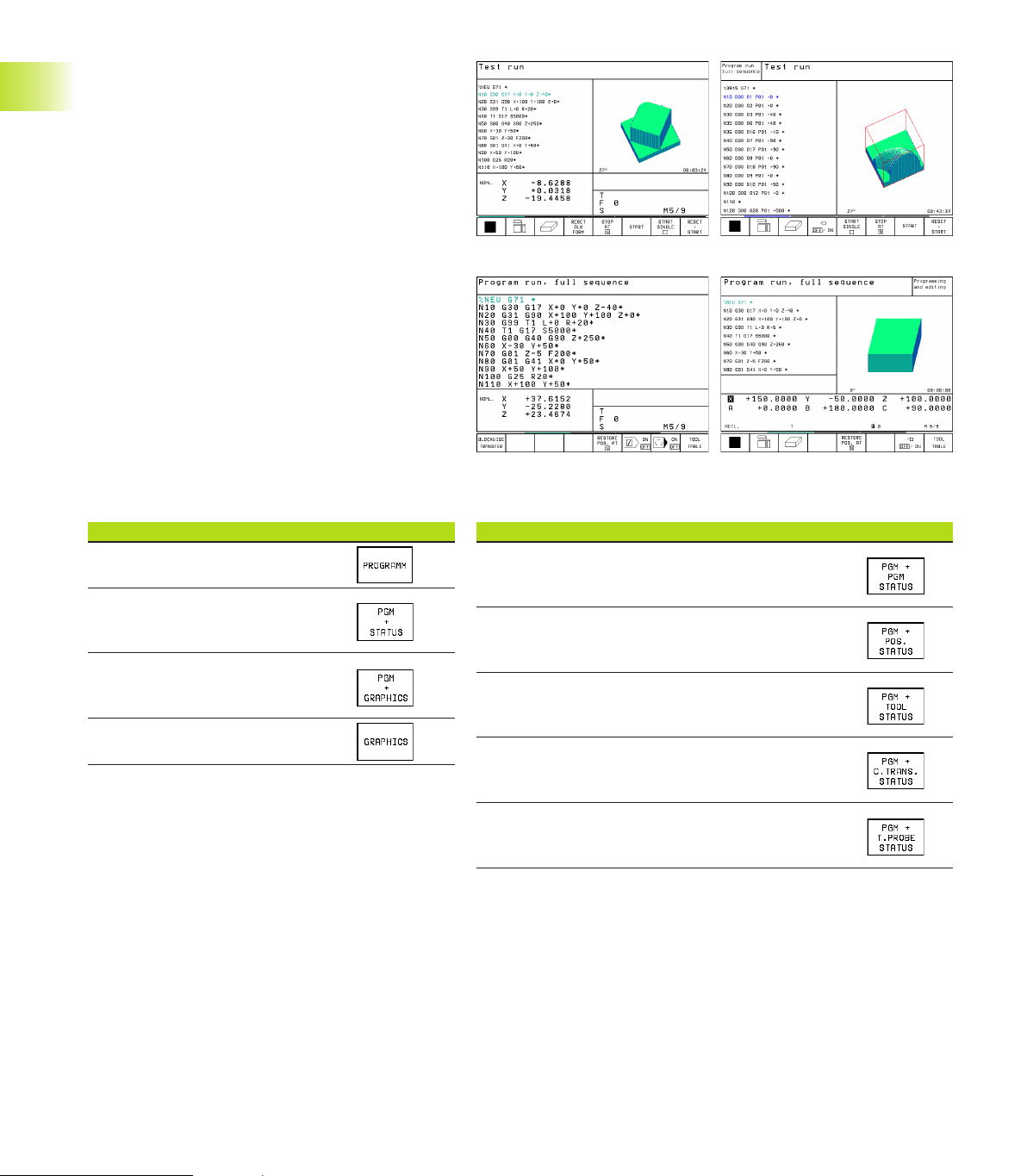
Page 22
Positioning with Manual Data Input
(MDI)
This mode of operation is used for programming
simple traversing movements, such as for face
milling or pre-positioning.
Soft keys for selecting the screen layout
Screen windows Soft key
Program
Left: positions. Right: status display.
(only TNC 426, TNC 430)
1.3 Modes of Operation
Left: program. Right: general program
information (only TNC 410)
Left: program. Right: positions and
coordinates (only TNC 410)
Left: program. Right: information on
tools (only TNC 410)
Left: program. Right: coordinate
transformations (only TNC 410)
6
1 Introduction
Page 23

Programming and Editing
In this mode of operation you can write your part
programs. The various cycles and Q-parameter
functions help you with programming and add
necessary information.
Soft keys for screen layout
(not for TNC 426, TNC 430)
Screen windows Soft key
Program
Left: program. Right: help graphics
for cycle programming
Left: program. Right:
programming graphics
Interactive Programming Graphics
1.3 Modes of Operation
7HEIDENHAIN TNC 410, TNC 426, TNC 430
Page 24
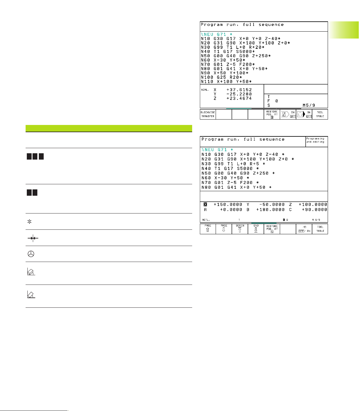
Test run
In the Test Run mode of operation, the TNC checks
programs and program sections for errors, such as
geometrical incompatibilities, missing or incorrect
data within the program or violations of the work
space. This simulation is supported graphically in
different display modes.
Soft keys for selecting the screen layout
See Program Run, Full Sequence.
Program Run, Full Sequence and
Program Run, Single Block
1.3 Modes of Operation
In the Program Run, Full Sequence mode of
operation the TNC executes a part program
continuously to its end or to a manual or
programmed stop. You can resume program run
after an interruption.
In the Program Run, Single Block mode of operation
you execute each block separately by pressing the
machine START button.
Soft keys for selecting the screen layout
Screen windows Soft key
Program
Left: program. Right: STATUS
(only TNC 426, TNC 430)
Left: program blocks, right: graphics
(only TNC 426, TNC 430)
Graphics (only TNC 426, TNC 430)
Screen windows Soft key
Left: program. Right: general
Program information (only TNC 410)
Left: program. Right: positions and
coordinates (only TNC 410)
Left: program. Right: information on
tools (only TNC 410)
Left: program.
Right: coordinate transformations (only TNC 410)
Left: program
Right: tool measurement (only TNC 410)
8
1 Introduction
Page 25
1.4 Status Displays
“General” status display
The status display informs you of the current state of the machine
tool. It is displayed automatically in the following modes of
operation:
■ Program Run, Single Block and Program Run, Full Sequence,
except if the screen layout is set to display graphics only, and
■ Positioning with Manual Data Input (MDI).
In the operating modes Manual and Electronic Handwheel, the
status display is shown in the large window.
Information in the status display
The Meaning
ACTL. Actual or nominal coordinates of the current position
X Y Z Machine axes; the TNC displays auxiliary axes in
lower-case letters. The sequence and quantity of displayed
axes is determined by the machine tool builder.
Refer to your machine manual for more information
F S M The displayed feed rate in inches corresponds to
one tenth of the effective value.
Spindle speed S, feed rate F and active M functions
Program run started
# Axis locked
Axis can be moved with the handwheel
Axes are moving in a tilted working
plane (not TNC 410)
1.4 Status Displays
Axes are moving under a basic
rotation
9HEIDENHAIN TNC 410, TNC 426, TNC 430
Page 26
Additional status displays
The additional status displays contain detailed information on the
program run. They can be called in all operating modes, except in
the Programming and Editing mode of operation.
To switch on the additional status display:
Call the soft-key row for screen layout.
<
1.4 Status Displays
You can choose between several additional status displays with the
following soft keys:
<
Select the layout option for the additional status
display.
Shift the soft-key rows until the STATUS soft
keys appear.
Select the desired additional status display,
e.g. general program information.
10
1 Introduction
Page 27
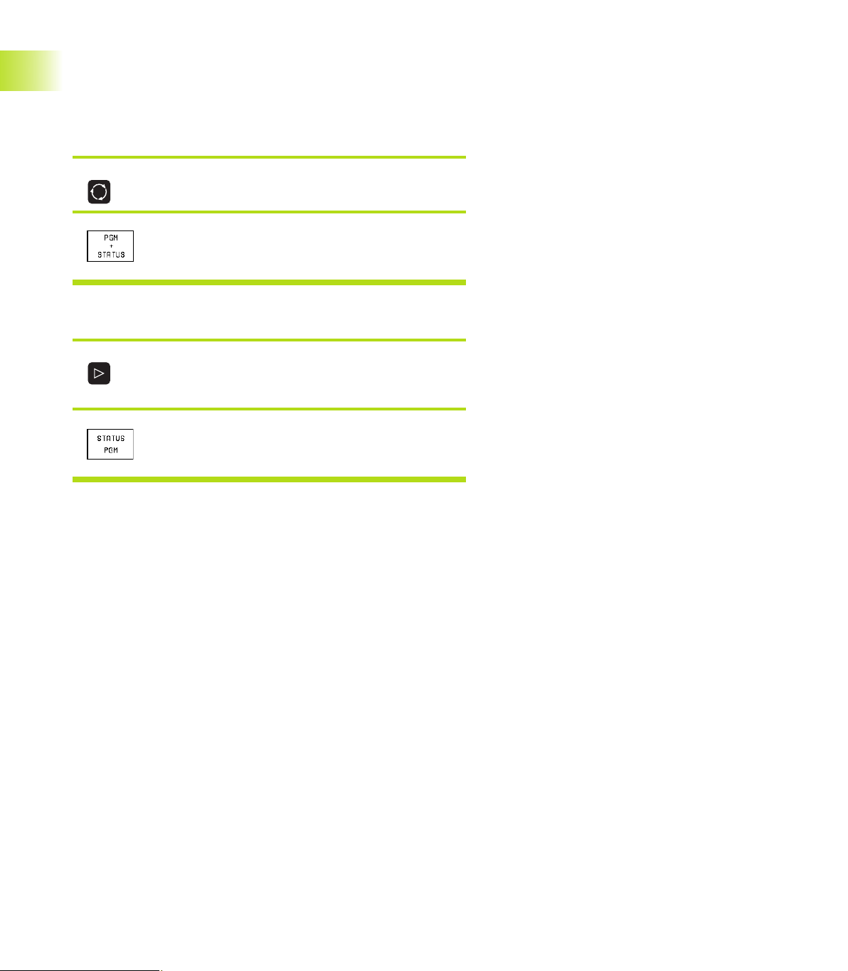
General program information
Name of main program
Active programs
Active machining cycle
Circle center CC (pole)
Operating time
Dwell time counter
Positions and coordinates
Position display
Type of position display, e.g. actual positions
Tilting angle for the working plane (not TNC 410)
Angle of a basic rotation
1.4 Status Displays
11HEIDENHAIN TNC 410, TNC 426, TNC 430
Page 28
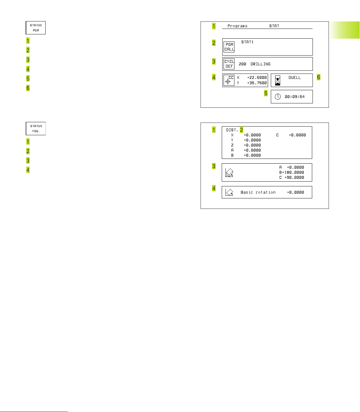
Information on tools
T: Tool number and name
RT: Number and name of a replacement tool
Tool axis
Tool length and radii
Oversizes (delta values) from TOOL CALL (PGM) and the tool
table (TAB)
Tool life, maximum tool life (TIME 1) and maximum tool life for
1.4 Status Displays
TOOL CALL (TIME 2)
Display of the active tool and the (next) replacement tool
Coordinate transformations
Name of main program
Active datum shift (Cycle 7)
Active rotation angle (Cycle 10)
Mirrored axes (Cycle 8)
Active scaling factor(s) (Cycles 11 / 26)
Scaling datum
For further information, refer to section 8.8 “Coordinate Transformation Cycles.”
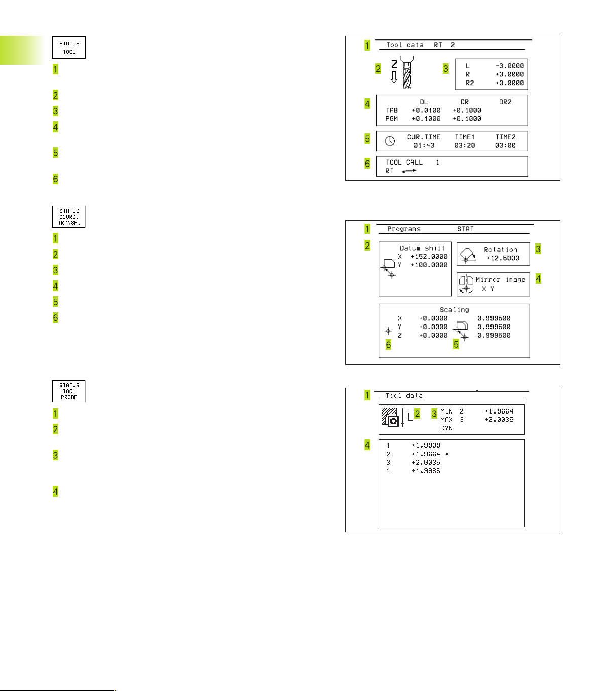
Tool measurement
Number of the tool to be measured
Display whether the tool radius or the tool length is being
measured
MIN and MAX values of the individual cutting edges and the
result of measuring the rotating tool (DYN = dynamic
measurement)
Cutting edge number with the corresponding measured value.
If the measured value is followed by an asterisk, the allowable
tolerance in the tool table was exceeded.
12
1 Introduction
Page 29
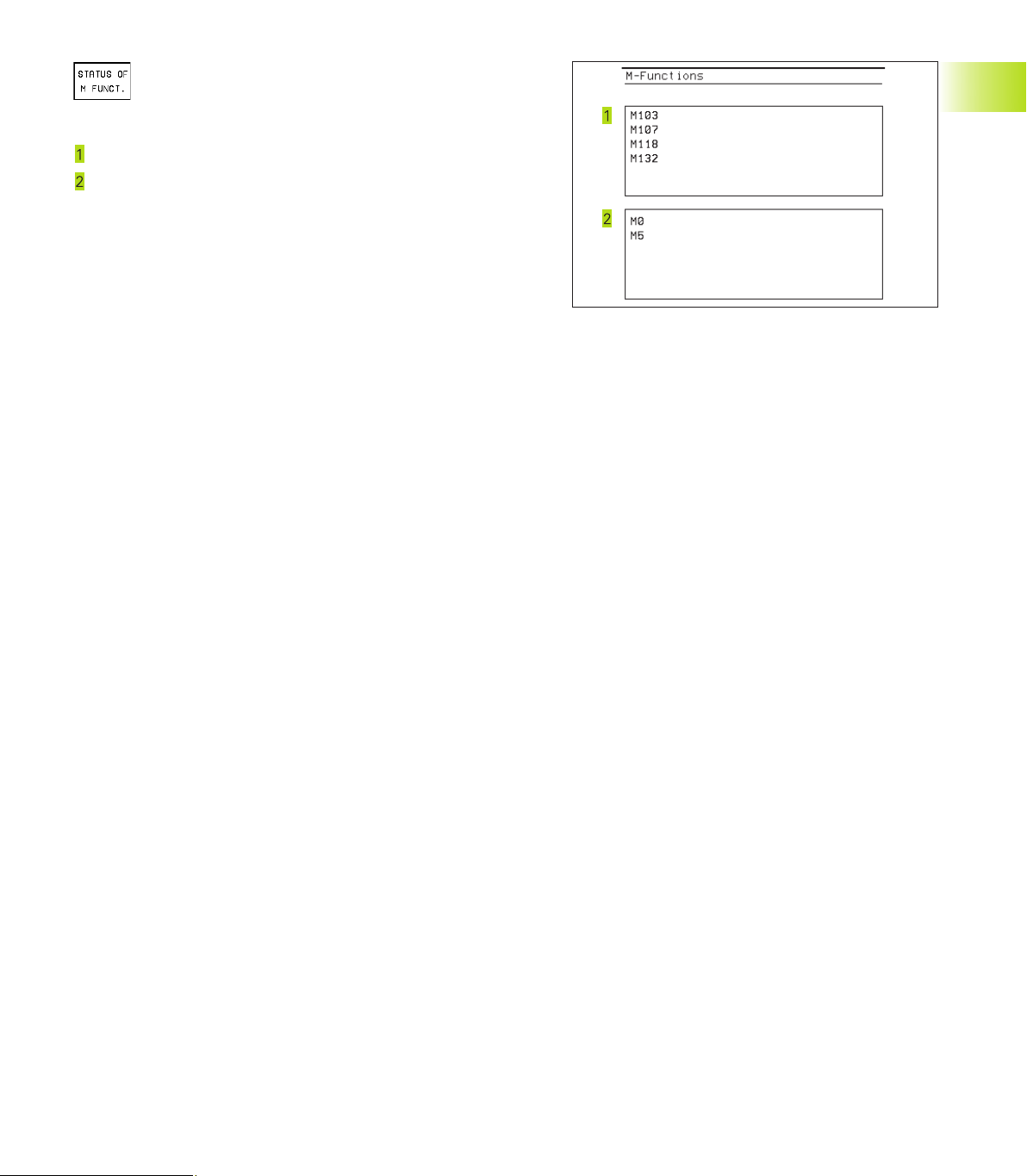
Active miscellaneous functions M
(only TNC 426, TNC 430 with NC
software 280 474-xx)
List of the active M functions with fixed meaning.
List of the active M functions with function assigned by machine
manufacturer.
1.4 Status Displays
13HEIDENHAIN TNC 410, TNC 426, TNC 430
Page 30
1.5 Accessories: HEIDENHAIN 3-D
Touch Probes and Electronic
Handwheels
3-D Touch Probes
With the various HEIDENHAIN 3-D touch probe systems you can:
■ Automatically align workpieces
■ Quickly and precisely set datums
■ Measure the workpiece during program run
■ Digitize 3-D surfaces (option), and
■ Measure and inspect tools
TS 220 and TS 630 touch trigger probes
These touch probes are particularly effective for automatic
workpiece alignment, datum setting, workpiece measurement and
for digitizing. The TS 220 transmits the triggering signals to the TNC
via cable and is a cost-effective alternative for applications where
digitizing is not frequently required.
The TS 630 features infrared transmission of the triggering signal to
the TNC. This makes it highly convenient for use on machines with
automatic tool changers.
Principle of operation: HEIDENHAIN triggering touch probes feature a
wear resisting optical switch that generates an electrical signal as
soon as the stylus is deflected. This signal is transmitted to the TNC,
which stores the current position of the stylus as an actual value.
During digitizing the TNC generates a program containing straight
line blocks in HEIDENHAIN format from a series of measured
position data. You can then output the program to a PC for further
processing with the SUSA evaluation software. This evaluation
software enables you to calculate male/female transformations or
correct the program to account for special tool shapes and radii that
differ from the shape of the stylus tip. If the tool has the same
radius as the stylus tip you can run these programs immediately.
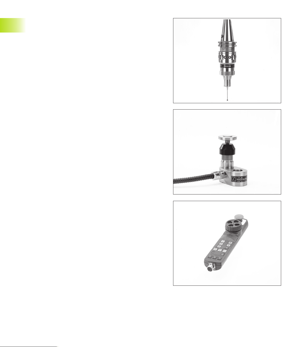
TT 120 tool touch probe for tool measurement
The TT 120 is a triggering 3-D touch probe for tool measurement
and inspection. Your TNC provides three cycles for this touch probe
with which you can measure the tool length and radius
automatically—either with the spindle rotating or stopped (only for
conversational programming).
The TT 120 features a particularly rugged design and a high degree
of protection, which make it insensitive to coolants and swarf. The
triggering signal is generated by a wear-resistant and highly reliable
1.5 Accessories: HEIDENHAIN 3-D Touch Probes and Electronic Handwheels
optical switch.
HR electronic handwheels
Electronic handwheels facilitate moving the axis slides precisely by
hand. A wide range of traverses per handwheel revolution is
available. Apart from the HR 130 and HR 150 integral handwheels,
HEIDENHAIN also offers the HR 410 portable handwheel.
14
1 Introduction
Page 31

2
Manual Operation and Setup
Page 32

2.1 Switch-on, Switch-off
Switch-On
Switch-on and traversing the reference points can vary
depending on the individual machine tool. Your machine
manual provides more detailed information.
ú Switch on the power supply for control and machine.
The TNC automatically initiates the following dialog
Memory Test
<
The TNC memory is automatically checked.
2.1 Switch-on, Switch-off
Power Interrupted
<
TNC message that the power was interrupted
— clear the message.
Translate PLC Program
<
The PLC program of the TNC is automatically compiled.
Relay Ext. DC Voltage Missing
<
Switch on the control voltage.
The TNC checks the functioning of the
EMERGENCY STOP circuit.
The TNC is now ready for operation in the
Manual Operation mode.
For the TNC 426, TNC 430:
The reference points need only be
traversed if the machine axes are to be
moved. If you intend only to write, edit or
test programs, you can select the
Programming and Editing or Test Run
modes of operation immediately after
switching on the control voltage.
You can then traverse the reference
points later by pressing the PASS OVER
REFERENCE soft key in the Manual
Operation mode.
Traversing the reference point in a tilted working
plane
The reference point of a tilted coordinate system
can be traversed by pressing the machine axis
direction buttons. The “tilting the working plane”
function (see section 2.5 “Tilting the Working
Plane”) must be active in the Manual Operation
mode. The TNC then interpolates the corresponding
axes.
The NC START button is not effective. Pressing this
button may result in an error message.
Make sure that the angle values entered in the
menu for tilting the working plane match the actual
angle of the tilted axis.
Manual Operation
Traverse Reference Points
<
Cross the reference points manually in the
displayed sequence: For each axis press the
machine START button, or
Cross the reference points in any sequence:
Press and hold the external direction button for
each axis until the reference point has been
traversed, or additionally for the TNC 410
Cross the reference points with several axes at
the same time: Use soft keys to select the axes
(axes are then shown highlighted on the
screen), and then press the machine START
button.
16
Switch-off
To prevent data being lost at switch-off, you need to
run down the operating system as follows:
ú Select the Manual mode
ú Select the function for run-down,
confirm again with the YES soft key.
ú When the TNC displays the message
„Now you can switch off the TNC“ in a
superimposed window, you may cut
off the power supply to the TNC.
Inappropriate switch-off of the TNC can
lead to data loss.
2 Manual Operation and Setup
Page 33

2.2 Moving the Machine Axes
Traversing with the machine axis direction buttons is a
machine-dependent function. Refer to your machine tool
manual.
To traverse with the machine axis direction buttons:
Select the Manual Operation mode.
<
Press the machine axis direction button and
hold it as long as you wish the axis to move.
...or move the axis continuously:
and Press and hold the machine axis direction
button, then press the machine START button:
The axis continues to move after you release
the keys.
2.2 Moving the Machine Axes
To stop the axis, press the machine STOP
button.
You can move several axes at a time with these two methods.
You can change the feed rate at which the axes are traversed with
the F soft key (see section 2.3 ”Spindle Speed S, Feed Rate F and
Miscellaneous Functions M”). This function is not available on
TNC 410.
17HEIDENHAIN TNC 410, TNC 426, TNC 430
Page 34

Traversing with the HR 410 electronic handwheel
The portable HR 410 handwheel is equipped with two permissive
buttons. The permissive buttons are located below the star grip.
You can only move the machine axes when an permissive button is
depressed (machine-dependent function).
The HR 410 handwheel features the following operating elements:
EMERGENCY STOP
Handwheel
Permissive buttons
Axis address keys
Actual-position-capture key
Keys for defining the feed rate (slow, medium, fast; the feed
rates are set by the machine tool builder)
2.2 Moving the Machine Axes
Direction in which the TNC moves the selected axis
Machine function
(set by the machine tool builder)
The red indicators show the axis and feed rate you have selected.
It is also possible to move the machine axes with the handwheel
during a program run.
To move an axis:
Select the Electronic Handwheel mode of
operation
Press and hold the permissive button.
<
Select the axis.
<
Select the feed rate.
<
or Move the active axis in the positive or negative
direction.
18
2 Manual Operation and Setup
Page 35

Incremental jog positioning
With incremental jog positioning you can move a machine axis by a
preset distance.
Select Manual or Electronic Handwheel mode
of operation
Z
<
Select incremental jog positioning: Switch the
INCREMENT soft key to ON
Jog increment:
<
Enter the jog increment in millimeters (here, 8
mm).
Enter the jog increment via soft key (preset softkey values). Not for TNC 426, TNC 430.
<
Press the machine axis direction button as often
as desired.
2.3 Spindle Speed S, Feed Rate F and
Miscellaneous Functions M
In the operating modes Manual and Electronic Handwheel, you can
enter the spindle speed S, feed rate F and the miscellaneous
functions M with soft keys. The miscellaneous functions are
described in Chapter 7 ”Programming: Miscellaneous Functions.”
8
8
8
X
16
2.3 Spindle Speed S, Feed Rate F and Miscellaneous Functions M
19HEIDENHAIN TNC 410, TNC 426, TNC 430
Page 36

Entering values
Example: Entering the spindle speed S
To enter the spindle speed, press the S soft key.
Spindle speed S =
<
1000 Enter the desired spindle speed,
and confirm your entry with the machine START
button.
2.4 Setting the Datum
The spindle speed S with the entered rpm is started with a
miscellaneous function.
Proceed in the same way to enter the feed rate F and the
miscellaneous functions M.
For the feed rate F (not true for TNC 410):
■ If you enter F=0, then the lowest feed rate from MP1020 is
effective
■ F is not lost during a power interruption
Changing the spindle speed and feed rate
With the override knobs you can vary the spindle speed S and feed
rate F from 0% to 150% of the set value.
The knob for spindle speed override is effective only on
machines with an infinitely variable spindle drive.
The machine tool builder determines which
miscellaneous functions M are available on your TNC and
what effects they have.
2.4 Datum Setting
(Without a 3-D Touch Probe)
You fix a datum by setting the TNC position display to the
coordinates of a known position on the workpiece.
Preparation
ú Clamp and align the workpiece.
ú Insert the zero tool with known radius into the spindle.
ú Ensure that the TNC is showing the actual position values.
20
2 Manual Operation and Setup
Page 37

Datum setting
Fragile workpiece? If the workpiece surface must not be scratched,
you can lay a metal shim of know thickness
tool axis datum value that is larger than the desired datum by the
d
.
value
Select the Manual Operation mode.
<
Move the tool slowly until it touches the
workpiece surface.
<
Select an axis (all axes can also be selected via
the ASCII keyboard)
Datum Set Z=
<
Zero tool in spindle axis: Set the display to a
known workpiece position (here, 0) or enter the
d
thickness
the tool radius.
Repeat the process for the remaining axes.
If you are using a preset tool, set the display of the tool axis to the
length L of the tool or enter the sum Z=L+d.
of the shim. In the tool axis, offset
d
on it. Then enter a
Y
Z
X
Y
X
2.5 Tilt the working plane (not TNC 410)
2.5 Tilt the working plane (not TNC 410)
The functions for tilting the working plane are interfaced
to the TNC and the machine tool by the machine tool
builder. With specific swivel heads and tilting tables, the
machine tool builder determines whether the entered
angles are interpreted as coordinates of the tilt axes or
as solid angles. Your machine manual provides more
detailed information.
The TNC supports the tilting functions on machine tools with swivel
heads and/or tilting tables. Typical applications are, for example,
oblique holes or contours in an oblique plane. The working plane is
always tilted around the active datum. The program is written as
usual in a main plane, such as the X/Y plane, but is executed in a
plane that is tilted relative to the main plane.
Z
Y
B
10°
X
21HEIDENHAIN TNC 410, TNC 426, TNC 430
Page 38

There are two functions available for tilting the working plane
■ 3-D ROT soft key in the Manual mode and Electronic Handwheel
mode (described below)
■ Tilting under program control: Cycle G80 WORKING PLANE in the
part program: see section ”8.9 Coordinate Transformation
Cycles.”
The TNC functions for “tilting the working plane” are coordinate
transformations in which the working plane is always perpendicular
to the direction of the tool axis.
When tilting the working plane, the TNC differentiates between
two machine types
Machines with tilting tables:
■ You must tilt the workpiece into the desired position for
machining by positioning the tilting table, for example with an L
block.
■ The position of the transformed tool axis does not change in
relation to the machine-based coordinate system. Thus if you
rotate the table — and therefore the workpiece — by 90° for
example, the coordinate system does not rotate. If you press the
Z+ axis direction button in the Manual Operation mode, the tool
moves in Z+ direction.
■ In calculating the transformed coordinate system, the TNC
2.5 Tilt the working plane (not TNC 410)
considers only the mechanically influenced offsets of the
particular tilting table (the so-called “translational” components).
Machines with swivel heads
■ You must bring the tool into the desired position for machining by
positioning the swivel head, for example with an L block.
■ The position of the transformed tool axis changes in relation to
the machine-based coordinate system. Thus if you rotate the
swivel head — and therefore the tool — in the B axis by 90° for
example, the coordinate system rotates also. If you press the
Z+ axis direction button in the Manual Operation mode, the tool
moves in X+ direction of the machine-based coordinate system.
■ In calculating the transformed coordinate system, the TNC
considers both the mechanically influenced offsets of the
particular swivel head (the so-called “translational” components)
and offsets caused by tilting of the tool (3-D tool length
compensation).
22
2 Manual Operation and Setup
Page 39

Traversing the reference points in tilted axes
With tilted axes, you use the machine axis direction buttons to
cross over the reference points. The TNC interpolates the
corresponding axes. Be sure that the function for tilting the working
plane is active in theManual Operation mode and the actual angle
of the tilted axis was entered in the menu field.
After you have positioned the rotary axes, set the datum in the
same way as for a non-tilted system. The TNC then converts the
datum for the tilted coordinate system. If your machine tool
features axis control, the angular values for this calculation are
taken from the actual position of the rotary axis.
You must not set the datum in the tilted working plane if
in machine parameter 7500 bit 3 is set. If you do, the
TNC will calculate the wrong offset.
If your machine tool is not equipped with axis control,
you must enter the actual position of the rotary axis in
the menu for manual tilting: The actual positions of one
or several rotary axes must match the entry. Otherwise
the TNC will calculate an incorrect datum.
Datum setting on machines with rotary tables
Position display in a tilted system
The positions displayed in the status window
(ACTL. and NOML.) are referenced to the tilted
coordinate system.
Limitations on working with the tilting function
■ The touch probe function Basic Rotation cannot
be used.
■ PLC positioning (determined by the machine tool
builder) is not possible.
■ Positioning blocks with M91/M92 are not
permitted.
The behavior of the TNC during datum setting depends
on the machine.Your machine manual provides more
detailed information.
The TNC automatically shifts the datum if you rotate the table and
the tilted working plane function is active.
MP 7500, bit 3=0
To calculate the datum, the TNC uses the difference between the
REF coordinate during datum setting and the REF coordinate of the
tilting axis after tilting. The method of calculation is to be used
when you have clamped your workpiece in proper alignment when
the rotary table is in the 0° position (REF value).
MP 7500, bit 3=1
If you rotate the table to align a workpiece that has been clamped in
an unaligned position, the TNC must no longer calculate the offset
of the datum from the difference of the REF coordinates. Instead of
the difference from the 0° position, the TNC uses the REF value of
the tilting table after tilting. In other words, it assumes that you
have properly aligned the workpiece before tilting.
2.5 Tilt the working plane (not TNC 410)
23HEIDENHAIN TNC 410, TNC 426, TNC 430
Page 40

To activate manual tilting:
To select manual tilting, press the 3-D ROT soft
key.
You can now select the desired menu option
with the arrow keys.
<
Enter the tilt angle.
<
To set the desired operating mode in menu option ”Tilt working
plane” to Active, select the menu option and shift with the ENT
key.
<
To conclude entry, press the END soft key.
To reset the tilting function, set the desired operating modes in
menu ”Tilt working plane” to Inactive.
2.5 Tilt the working plane (not TNC 410)
If the Working Plane function is active and the TNC moves the
machine axes in accordance with the tilted axes, the status display
shows the symbol
If you set the function ”Tilt working plane” for the operating mode
Program Run to Active, the tilt angle entered in the menu becomes
active in the first block of the part program. If you are using Cycle
G80 WORKING PLANE in the part program, the angular values
defined in the cycle (starting at the cycle definition) are effective.
Angular values entered in the menu will be overwritten.
.
24
2 Manual Operation and Setup
Page 41

3
Positioning with Manual Data
Input (MDI)
25HEIDENHAIN TNC 410, TNC 426, TNC 430
Page 42

3.1 Program and Run Simple
Machining Operations
The operating mode Positioning with Manual Data Input is
particularly convenient for simple machining operations or prepositioning of the tool. You can write a short program in HEIDENHAIN conversational programming or in ISO format, and execute
them immediately. You can also call TNC cycles. The program is
stored in the file $MDI. In the operating mode Positioning with MDI,
the additional status displays can also be activated.
Select the operating mode Positioning with
MDI.
Program the $MDI file as desired.
<
To start the selected block: Press the machine
START button.
Limitations for TNC 410:
The following functions are not available:
- Tool radius compensation
- Programming and program run graphics
- Programmable probe functions
- Subprograms, program section repeats
- Contouring functions G06, G02 and G03 with R, G24
and G25
- Program call with %
Limitations of the TNC 426, TNC 430:
The following functions are not available:
- Program call with %
- Program run graphics
50
Z
Y
X
50
3.1 Programming and Executing Simple Machining Operations
26
3 Positioning with Manual Data Input (MDI)
Page 43

Example 1
A hole with a depth of 20 mm is to be drilled into a single
workpiece. After clamping and aligning the workpiece and setting
the datum, you can program and execute the drilling operation in a
few lines.
First you pre-position the tool with G00 and G01 blocks (straight-line
blocks) to the hole center coordinates at a setup clearance of 5 mm
above the workpiece surface. Then drill the hole with Cycle G83
PECKING.
%$MDI G71 *
N10 G99 T1 L+0 R+5 *
N20 T1 G17 S2000 *
N30 G00 G40 G90 Z+200 *
N40 X+50 Y+50 M3 *
N50 G01 Z+2 F2000 *
N60 G83
P01 +2
P02 -20
P03 +10
P04 0.5
P05 250 *
N70 G79 *
N80 G00 G40 Z+200 M2 *
N99999 %$MDI G71 *
Define tool: zero tool, radius 5
Call tool: spindle axis Z,
Spindle speed 2000 rpm
Retract tool (rapid traverse)
Move the tool at rapid traverse to a position above the
hole. Spindle on.
Position tool to 5 mm above hole
Define Cycle G83 PECKING:
Setup clearance of the tool above the hole
Total hole depth (Algebraic sign=working direction)
Depth of each infeed before retraction
Dwell time in seconds at the hole bottom
Feed rate for pecking
Call Cycle G83
Retract tool
End of program
The straight-line function is described in section 6.4 ”Path Contours
— Cartesian Coordinates,” the G83 PECKING cycle in section 8.3
”Drilling Cycles.”
3.1 Programming and Executing Simple Machining Operations
27HEIDENHAIN TNC 410, TNC 426, TNC 430
Page 44

Example 2
Correcting workpiece misalignment on machines with rotary tables
Use the 3-D touch probe to rotate the coordinate system. See
section ”12.1 Touch Probe Cycles in the Manual and Electronic
Handwheel Modes,” section ”Compensating Workpiece
Misalignment.”
<
Write down the Rotation Angle and cancel the Basic Rotation.
<
Select operating mode: Positioning with MDI.
<
Select the axis of the rotary table, enter the
rotation angle you wrote down previously and
set the feed rate.
For example: G00 G40 G90 C+2.561 F50
<
Conclude entry.
<
Press the machine START button: The rotation of
the table corrects the misalignment.
3.1 Programming and Executing Simple Machining Operations
28
3 Positioning with Manual Data Input (MDI)
Page 45

Save or delete programs from %$MDI
The %$MDI file is generally intended for short programs that are
only needed temporarily. Nevertheless, you can store a program, if
necessary, by proceeding as described below:
Select the
Programming and Editing mode of operation
<
To call the file manager, press the PGM MGT
key (program management).
<
Tag the %$MDI file
<
Select „Copy file“: Press the COPY soft key
Target file =
<
Hole
<
Enter the name under which you want to save
the current contents of the $MDI file.
TNC 410: Start copying by pressing the ENT key
TNC 426, TNC 430: Press the EXECUTE soft key
to start copying
<
To close the file manager, press the END soft
key.
Erasing the contents of the %$MDI file is done in a similar way:
Instead of copying the contents, however, you erase them with the
DELETE soft key. The next time you select the operating mode
Positioning with MDI, the TNC will display an empty %$MDI file.
TNC 426, TNC 430:
The %$MDI file may not be selected in the
Programming and Editing mode during the erasure
procedure.
3.1 Programming and Executing Simple Machining Operations
29HEIDENHAIN TNC 410, TNC 426, TNC 430
Page 46

Page 47

4
Programming:
Fundamentals of NC, File
Management,
Programming Aids, Pallet
Management
Page 48

4.1 Fundamentals of NC
Position encoders and reference marks
The machine axes are equipped with position encoders that
register the positions of the machine table or tool. When a machine
axis moves, the corresponding position encoder generates an
electrical signal. The TNC evaluates this signal and calculates the
precise actual position of the machine axis.
If there is an interruption of power, the calculated position will no
longer correspond to the actual position of the machine slide. The
CNC can re-establish this relationship with the aid of reference
marks when power is returned. The scales of the position encoders
contain one or more reference marks that transmit a signal to the
TNC when they are crossed over. From the signal the TNC identifies
4.1 Fundamentals of NC
that position as the machine-axis reference point and can reestablish the assignment of displayed positions to machine axis
positions.
Linear encoders are generally used for linear axes. Rotary tables
and tilt axes have angle encoders. If the position encoders feature
distance-coded reference marks, you only need to move each axis a
maximum of 20 mm (0.8 in.) for linear encoders, and 20° for angle
encoders, to re-establish the assignment of the displayed positions
to machine axis positions.
Z
Y
X
X
MP
X (Z,Y)
32
4 Programming: Fundamentals of NC, File Management,
Programming Aids, Pallet Management
Page 49

Reference system
A reference system is required to define positions in a plane or in
space. The position data are always referenced to a predetermined
point and are described through coordinates.
The Cartesian coordinate system (a rectangular coordinate system)
is based on three coordinate axes X, Y and Z. The axes are mutually
perpendicular and intersect at one point called the datum. A
coordinate identifies the distance from the datum in one of these
directions. A position in a plane is thus described through two
coordinates, and a position in space through three coordinates.
Coordinates that are referenced to the datum are referred to as
absolute coordinates. Relative coordinates are referenced to any
other known position (datum) you define within the coordinate
system. Relative coordinate values are also referred to as
incremental coordinate values.
Reference systems on milling machines
When using a milling machine, you orient tool movements to the
Cartesian coordinate system. The illustration at right shows how
the Cartesian coordinate system describes the machine axes. The
figure at right illustrates the “right-hand rule” for remembering the
three axis directions: the middle finger is pointing in the positive
direction of the tool axis from the workpiece toward the tool (the Z
axis), the thumb is pointing in the positive X direction, and the index
finger in the positive Y direction.
The TNC 410 can control a maximum of 4 axes, the TNC 426 a
maximum of 5 axes and the TNC 430 a maximum of 9 axes. The
axes U, V and W are secondary linear axes parallel to the main axes
X, Y and Z, respectively. Rotary axes are designated as A, B and C.
The illustration at lower right shows the assignment of secondary
axes and rotary axes to the main axes.
+Y
Z
Y
X
4.1 Fundamentals of NC
+Z
+Y
+X
+Z
+X
V+
Z
Y
W+
C+
B+
A+
X
U+
33HEIDENHAIN TNC 410, TNC 426, TNC 430
Page 50

Polar coordinates
If the production drawing is dimensioned in Cartesian coordinates,
you also write the part program using Cartesian coordinates. For
parts containing circular arcs or angles it is often simpler to give the
dimensions in polar coordinates.
While the Cartesian coordinates X, Y and Z are three-dimensional
and can describe points in space, polar coordinates are twodimensional and describe points in a plane. Polar coordinates have
their datum at the so-called pole. A position in a plane can be clearly
defined by the
■ Polar radius R: the distance from the pole to the position, and the
■ Polar angle H, the size of the angle between the reference axis
and the line that connects the pole with the position.
4.1 Fundamentals of NC
See figure at lower right.
Definition of pole and angle reference axis
The pole is set by entering two Cartesian coordinates in one of the
three planes. These coordinates also set the reference axis for the
polar angle H.
10
Z
Y
R
H
2
H
3
R
CC
R
H
1
0°
X
30
Y
Coordinates of the pole (plane) Reference axis of the angle
I and J +X
J and K +Y
K and I +Z
J
I
Z
K
I
X
Y
Z
Y
K
J
X
X
34
4 Programming: Fundamentals of NC, File Management,
Programming Aids, Pallet Management
Page 51

Absolute and relative workpiece positions
Absolute workpiece positions
Absolute coordinates are position coordinates that are referenced
to the datum of the coordinate system (origin). Each position on the
workpiece is uniquely defined by its absolute coordinates.
Example 1: Holes dimensioned in absolute coordinates
Hole
X=10 mm X=30 mm X=50 mm
Y=10 mm Y=20 mm Y=30 mm
Hole Hole
Y
30
20
10
Relative workpiece positions
Relative coordinates are referenced to the last programmed
nominal position of the tool, which serves as the relative (imaginary)
datum. When you write a part program in incremental coordinates,
you thus program the tool to move by the distance between the
previous and the subsequent nominal positions. Incremental
coordinates are therefore also referred to as chain dimensions.
To program a position in incremental coordinates, enter the
function G91 before the axis.
Example 2: Holes dimensioned with relative coordinates
Absolute coordinates of hole
:
X= 10 mm
Y= 10 mm
referenced to hole Hole referenced to hole
Hole
G91 X= 20 mm G91 X= 20 mm
G91 Y= 10 mm G91 Y= 10 mm
Absolute and incremental polar coordinates
Absolute polar coordinates always refer to the pole and the
reference axis.
Incremental polar coordinates always refer to the last programmed
nominal position of the tool.
10
10 10
3010
50
4.1 Fundamentals of NC
Y
X
20
10
20
Y
X
10
G91+R
R
G91+H
R
G91+H
CC
R
H
0°
X
30
35HEIDENHAIN TNC 410, TNC 426, TNC 430
Page 52

Selecting the datum
A production drawing identifies a certain form element of the
workpiece, usually a corner, as the absolute datum. Before setting
the datum, you align the workpiece with the machine axes and
move the tool in each axis to a known position relative to the
workpiece. You then set the TNC display to either zero or a
predetermined position value. This establishes the reference
system for the workpiece, which will be used for the TNC display
and your part program.
If the production drawing is dimensioned in relative coordinates,
simply use the coordinate transformation cycles. For further
information, refer to section 8.9 ”Coordinate Transformation
Cycles.”
If the production drawing is not dimensioned for NC, set the datum
4.1 Fundamentals of NC
at a position or corner on the workpiece, which is the most suitable
for deducing the dimensions of the remaining workpiece positions.
The fastest, easiest and most accurate way of setting the datum is
by using a 3-D touch probe from HEIDENHAIN. For further
information, refer to section 12.2 “Setting the Datum with a 3-D
Touch Probe.”
Example
The workpiece drawing at right illustrates the holes
are dimensioned to an absolute datum with the coordinates X=0
Y=0. The holes
absolute coordinates X=450 Y=750. By using the DATUM SHIFT
cycle you can shift the datum temporarily to the position X=450,
Y=750 and program the holes
calculations.
to are referenced to a relative datum with the
to without any further
to , which
750
320
Z
Y
X
Y
150
0
-150
0,1
±
300
0
36
325
450 900
950
4 Programming: Fundamentals of NC, File Management,
Programming Aids, Pallet Management
X
Page 53

4.2 File Management: Fundamentals
Files
When you write a part program on the TNC, you must first enter a
file name. The TNC then stores the program as a file with the same
name. You can also store text and tables as files.
The TNC provides a special file management window in which you
can easily find and manage your files. Here you can call, copy,
rename and erase files.
In the TNC 410 you can manage a max. 64 files with a total of up to
128 KB.
The TNC 426, TNC 430 can manage any number of files. However,
their total size must not exceed 1.5 gigabytes.
File names
The name of a file can have up to 16 characters (TNC 410:
8 characters). When you store programs, tables and texts as files,
the TNC adds an extension to the file name, separated by a point.
This extension identifies the file type (see table at right).
PROG20 .H
File name File type
Data backup TNC 426, TNC 430
We recommend saving newly written programs and files on a PC at
regular intervals. You can do this with the cost-free backup program
TNCBACK.EXE from HEIDENHAIN. Your machine tool builder can
provide you with a copy of TNCBACK.EXE.
You also need a floppy disk on which all the machine-specific data
(PLC program, machine parameters, etc.) of your machine tool are
stored. Please contact your machine tool builder for more
information on both the backup program and the floppy disk.
Files in the TNC Type
Programs
in HEIDENHAIN conversational format .H
in ISO format .I
Tables for
Tools .T
Tool changer (TNC 410: 1 table) .TCH
Datums .D
Points .PNT
Pallets (not TNC 410) .P
Text as
ASCII files (not TNC 410) .A
4.2 File Management: Fundamentals
Saving the contents of the entire hard disk (up to 1.5 GB)
can take up to several hours. In this case, it is a good idea
to save the data outside of working hours, (e.g.
overnight), or to use the PARALLEL EXECUTE function to
copy in the background while you work.
37HEIDENHAIN TNC 410, TNC 426, TNC 430
Page 54

4.3 Standard file management
TNC 426, TNC 430
Use the standard file manager if you want to store all of
the files in one directory, or if you are used to working
with the file manager on old TNC controls.
Set the MOD function PGM MGT to Standard (see
section 13.9) .
Calling the file manager
Press the PGM MGT:
The TNC displays the file management window
(see Fig. at top right)
The window shows you all of the files that are stored in the TNC.
Each file is shown with additional information, see table at center
right.
Display Meaning
FILE NAME Name with max. 16 characters
and file type
BYTE File size in bytes
Selecting a file
Calling the file manager
<
4.3 Standard File Management TNC 426, TNC 430
Use the arrow keys to move the highlight to the file you wish to
select:
Move the highlight up or down.
<
or Select a file: Press the SELECT soft key
or ENT
STATUS Property of the file:
E Program is in the
Programming and Editing
mode of operation
S Program is in the
Program is selected in the
Test RUN mode of operation
M Program is in the
Program Run mode of
operation.
P File is protected against
editing and erasure
(Protected)
Display of long file directories Soft key
Move pagewise up through
the file directory.
Move pagewise down through
the file directory
38
4 Programming: Fundamentals of NC, File Management,
Programming Aids, Pallet Management
Page 55

Deleting a file
Calling the file manager
<
Use the arrow keys to move the highlight to the file you wish to
delete:
Move the highlight up or down.
<
Delete a file: Press the DELETE soft key
Delete ........ file ?
<
Press the YES soft key to confirm, or
the NO soft key to abort.
Copying a file
Calling the file manager
<
Use the arrow keys to move the highlight to the file you wish to
copy:
Move the highlight up or down.
<
Copy a file: Press the COPY soft key
Target file =
<
Enter the name of the new file and confirm your entry with the
ENT key or EXECUTE soft key. A status window appears on the
TNC, informing about the copying progress. As long as the TNC
is copying, you can no longer work, or
If you wish to copy very long programs, enter the new file name
and confirm with the PARALLEL EXECUTE soft key. The file will
now be copied in the background, so you can continue to work
while the TNC is copying.
4.3 Standard File Management TNC 426, TNC 430
39HEIDENHAIN TNC 410, TNC 426, TNC 430
Page 56

Data transfer to or from an external data medium
Before you can transfer data to an external data medium,
you must set the interface (see section 13.6 ”Setting the
Data Interfaces for TNC 426, TNC 430”).
Calling the file manager
<
Activate data transfer: press the EXT soft key. In
the left half of the screen, the TNC shows all of
files that are stored on the TNC, and in the
the
right half of the screen,
stored on the external data medium.
<
Use the arrow keys to highlight the file(s) that you want to
transfer:
Move the highlight up and down within a
window
Move the highlight from the left to the right
window, and vice versa.
all of the files that are
If you are transferring from the TNC to the external medium,
move the highlight in the left window onto the file that is to be
transferred.
4.3 Standard File Management TNC 426, TNC 430
If you are transferring from the external medium to the TNC,
move the highlight in the right window onto the file that is to be
transferred.
<
Transfer a single file: Press the COPY soft key, or
Transfer several files: Press
TAG (marking functions, see table on right), or
transfer all files by pressing the TNC EXT soft
key
<
Tagging functions Soft key
Tag a single file
Tag all files
Untag a single file
Untag all files
Copy all tagged files
40
4 Programming: Fundamentals of NC, File Management,
Programming Aids, Pallet Management
Page 57

Confirm with the EXECUTE or with the ENT key. A status
window appears on the TNC, informing about the copying
progress, or
If you wish to transfer more than one file or longer files,
press the PARALLEL EXECUTE soft key. The TNC then copies the
file in the background.
<
To stop transfer, press the TNC soft key. The
standard file manager window is displayed
again.
Selecting one of the last 10 files selected
Calling the file manager
<
Display the last 10 files selected: Press LAST
FILES soft key
Use the arrow keys to move the highlight to the file you wish to
select:
Move the highlight up or down.
<
or Select a file: Press the SELECT soft key
or ENT
4.3 Standard File Management TNC 426, TNC 430
41HEIDENHAIN TNC 410, TNC 426, TNC 430
Page 58

Renaming a file
Calling the file manager
<
Use the arrow keys to move the highlight to the file you wish to
rename:
Move the highlight up or down.
<
To rename the file, press the RENAME key.
Target file =
<
Enter the name of the new file and confirm your entry with the
ENT key or EXECUTE soft key.
Protect file / Cancel file protection
Calling the file manager
<
Use the arrow keys to move the highlight to the file you wish to
protect or whose protection you wish to cancel:
4.3 Standard File Management TNC 426, TNC 430
Move the highlight up or down.
<
Press the PROTECT soft key to enable file
protection The file now has status P, or
To cancel file protection, press the UNPROTECT
soft key. The P status is canceled.
42
4 Programming: Fundamentals of NC, File Management,
Programming Aids, Pallet Management
Page 59

4.4 Expanded File Management
TNC 426, TNC 430
Select the file manager with additional functions if you
wish to store files in various different directories.
Set the MOD function PGM MGT (see section 13.9) to
Enhanced!
See also section 4.2 ”File Management: Fundamentals”!
Directories
To ensure that you can easily find your files, we recommend that
you organize your hard disk into directories. You can divide a
directory up into further directories, which are called subdirectories.
The TNC can manage up to 6 directory levels!
If you save more than 512 files in one directory, the TNC
no longer sorts them alphabetically!
Directory names
The name of a directory can contain up to 8 characters and does not
have an extension. If you enter more than 8 characters for the
directory name, the TNC will shorten the name to 8 characters.
Paths
A path indicates the drive and all directories and subdirectories
under which a file is saved. The individual names are separated by
the symbol “\”.
Example: On drive TNC:\, the directory AUFTR1 was created. Under
this directory, the subdirectory NCPROG was created, and the part
program PROG1.I copied into this subdirectory. The part program
now has the following path:
TNC:\AUFTR1\NCPROG\PROG1.I
The chart at right illustrates an example of a directory display with
different paths.
TNC:\
AUFTR1
NCPROG
WZTAB
A35K941
ZYLM
TESTPROG
HUBER
4.4 Expanded File Management TNC 426, TNC 430
KAR25T
43HEIDENHAIN TNC 410, TNC 426, TNC 430
Page 60

Overview: Functions of the expanded file manager
Function Soft key
Copy (and convert) individual files
Display a specific file type
Display the last 10 files that were selected
Erase a file or directory
Tag a file
Renaming a file
Protect a file against editing and erasure
Cancel file protection
Network drive management (Ethernet option only)
Copying a directory
Display all the directories of a particular drive
4.4 Expanded File Management TNC 426, TNC 430
Delete directory with all its subdirectories
44
4 Programming: Fundamentals of NC, File Management,
Programming Aids, Pallet Management
Page 61

Calling the file manager
Press the PGM MGT:
The TNC displays the file management window
(see Fig. at top right for default setting. If the
TNC displays a different screen layout, press the
WINDOW soft key)
The narrow window at left shows three drives . If the TNC is
connected to a network, it also displayed the connected network
drives. Drives designate devices with which data are stored or
transferred. One drive is the hard disk of the TNC. Other drives are
the interfaces (RS232, RS422, Ethernet), which can be used, for
example, to connect a personal computer. The selected (active)
drive is shown in a different color.
In the lower part of the narrow window the TNC shows all
directories
file symbol to the left and the directory name to the right. The TNC
displays a subdirectory to the right of and below its parent directory.
The selected (active) directory is depicted in a different color.
The wide window at on the right side shows all the files
stored in the selected directory. Each file is shown with additional
information that is illustrated in the table on the next page.
of the selected drive. A drive is always identified by a
that are
Display Meaning
FILE NAME Name with max. 16 characters
and file type
BYTE File size in bytes
STATUS Property of the file:
E Program is in the
Programming
and Editing
mode of operation
4.4 Expanded File Management TNC 426, TNC 430
S Program is in the
Program is selected in the
Test RUN mode of operation
M Program is in the
Program Run mode of
operation.
P File is protected against
editing and erasure
(Protected)
DATE Date the file
was last changed
TIME Time the file
was last changed
45HEIDENHAIN TNC 410, TNC 426, TNC 430
Page 62

To select drives, directories and files:
Calling the file manager
<
With the arrow keys or the soft keys, you can move the highlight to
the desired position on the screen:
Move the highlight from the left to the right
window, and vice versa.
Move the highlight up and down within a
window
Move the highlight one page up or
down within a window
1st step: select drive:
Move the highlight to the desired drive in the left window:
<
or Select drive: Press the SELECT soft key
or ENT
4.4 Expanded File Management TNC 426, TNC 430
2nd step: select directory:
Move the highlight to the desired directory in the left window —
the right window automatically shows all files stored in the
highlighted directory.
46
4 Programming: Fundamentals of NC, File Management,
Programming Aids, Pallet Management
Page 63

3rd step: select a file:
Press the SELECT TYPE soft key
Press the soft key for the desired file type, or
Press the SHOW ALL soft key to display all files
Move the highlight to the desired file in the right window
<
or The selected file is opened in the
operating mode from which you have
the called file manager: Press ENT or
the SELECT soft key.
To create a new directory (only possible on the
TNC's hard disk drive):
Move the highlight in the left window to the directory in which
you want to create a subdirectory.
<
NEW
Create \NEW directory ?
<
Enter the new file name, and confirm with ENT.
Press the YES soft key to confirm, or
the NO soft key to abort.
4.4 Expanded File Management TNC 426, TNC 430
47HEIDENHAIN TNC 410, TNC 426, TNC 430
Page 64

Copying a file
ú Move the highlight to the file you wish to copy.
ú Press the COPY soft key to select the copying
function.
ú Enter the name of the destination file and confirm your entry with
the ENT key or EXECUTE soft key: The TNC copies the file into the
active directory. The original file is retained.
Press the PARALLEL EXECUTE soft key to copy the file in the
background. Copying in the background permits you to continue
working while the TNC is copying. This can be useful if you are
copying very large files that take a long time. While the TNC is
copying in the background you can press the INFO PARALLEL
EXECUTE soft key (under MORE FUNCTIONS, second soft-key
row) to check the progress of copying.
Copying a table
If you are copying tables, you can overwrite individual lines or
columns in the target table with the REPLACE FIELDS soft key.
Prerequisites:
■ The target table must exist.
■ The file to be copied must only contain the columns or lines you
want to replace.
Example:
With a tool presetter you have measured the length and radius of
10 new tools. The tool presetter then generates the tool table
TOOL.T with 10 lines (for the 10 tools) and the columns
■ Tool number
■ Tool length
4.4 Expanded File Management TNC 426, TNC 430
■ Tool radius
If you wish to copy this file to the TNC, the TNC asks if you wish to
overwrite the existing TOOL.T tool table:
■ If you press the YES soft key, the TNC will completely overwrite
the current TOOL.T tool table. After this copying process the new
TOOL.T table consists of 10 lines. The only remaining columns in
the table are tool number, tool length and tool radius.
■ If you press the REPLACE FIELDS soft key, the TNC merely
overwrites the first 10 lines of the columns number, length and
radius in the TOOL.T file. The data of the other lines and columns
is not changed.
Copying a directory
Move the highlight in the left window onto the directory you want
to copy. Press the COPY DIR soft key instead of the COPY soft key.
Subdirectories are also copied at the same time.
48
4 Programming: Fundamentals of NC, File Management,
Programming Aids, Pallet Management
Page 65

Selecting one of the last 10 files selected
Calling the file manager
<
Display the last 10 files selected: Press LAST
FILES soft key
Use the arrow keys to move the highlight to the file you wish to
select:
Move the highlight up or down.
<
or Select a file: Press the SELECT soft key
or ENT
Deleting a file
ú Move the highlight to the file you want to delete.
ú To select the erasing function, press the DELETE soft
key.
The TNC inquires whether you really intend to erase
the file.
ú To confirm, press the YES soft key;
To abort erasure, press the NO soft key.
4.4 Expanded File Management TNC 426, TNC 430
Erase a directory
ú Erase all files and subdirectories stored in the directory that you
wish to erase.
ú Move the highlight to the directory you want to delete.
ú To select the erasing function, press the DELETE soft
key. The TNC inquires whether you really intend to
erase the directory.
ú To confirm, press the YES soft key;
To abort erasure, press the NO soft key.
49HEIDENHAIN TNC 410, TNC 426, TNC 430
Page 66

Tagging files
Some functions, such as copying or erasing files, can not only be
used for individual files, but also for several files at once. To tag
several files, proceed as follows:
Move the highlight to the first file.
<
To display the marking functions, press the TAG
soft key.
Tagging functions Soft key
Tagging single files
Tag all files in the
directory
Untag a single file
Untag all files
<
Tag a file by pressing the TAG FILE soft key.
<
Move the highlight to the next file you wish to tag:
<
You can tag several files in this way, as desired.
To copy the tagged files, press the COPY TAG
soft key, or
Delete the tagged files by
4.4 Expanded File Management TNC 426, TNC 430
pressing END to end the marking
function, and then DELETE to delete
the tagged files.
Renaming a file
ú Move the highlight to the file you wish to rename.
ú Select the renaming function.
ú Enter the new file name; the file type cannot be
changed.
ú To execute renaming, press the ENT key.
Copy all tagged files
50
4 Programming: Fundamentals of NC, File Management,
Programming Aids, Pallet Management
Page 67

Additional Functions
Protecting a file/Canceling file protection
ú Move the highlight to the file you want to protect.
ú To select the additional functions, press the MORE
FUNCTIONS key.
ú To enable file protection, press the PROTECT soft key.
The file now has status P.
To cancel file protection, proceed in the same way using the
UNPROTECT soft key.
Erase a directory together with all its subdirectories and files.
ú Move the highlight in the left window onto the directory you want
to erase.
ú To select the additional functions, press the MORE
FUNCTIONS key.
ú Press DELETE ALL to erase the directory together
with its subdirectories.
ú To confirm, press the YES soft key;
To abort erasure, press the NO soft key.
4.4 Expanded File Management TNC 426, TNC 430
51HEIDENHAIN TNC 410, TNC 426, TNC 430
Page 68

Data transfer to or from an external data medium
Before you can transfer data to an external data medium,
you must set the interface (see section 13.6 ”Setting the
Data Interfaces for TNC 426, TNC 430”).
Calling the file manager
<
Select the screen layout for data transfer: press
the WINDOW soft key. In the left half of the
screen, the TNC shows all of the
stored on the TNC, and in the right half of the
screen,
external data medium.
<
Use the arrow keys to highlight the file(s) that you want to
transfer:
Move the highlight up and down within a
window
Move the highlight from the left to the right
window, and vice versa.
all of the files that are stored on the
files that are
If you are transferring from the TNC to the external medium,
move the highlight in the left window onto the file that is to be
transferred.
4.4 Expanded File Management TNC 426, TNC 430
If you are transferring from the external medium to the TNC,
move the highlight in the right window onto the file that is to be
transferred.
<
Transfer a single file: Press the COPY soft key, or
To transfer several files, use the
TAG soft key (in the second soft-key row, see
also Tagging functions earlier on in this chapter),
or
transfer all files by pressing the TNC EXT soft
key
<
52
4 Programming: Fundamentals of NC, File Management,
Programming Aids, Pallet Management
Page 69

Confirm with the EXECUTE or with the ENT key. A status
window appears on the TNC, informing about the copying
progress, or
If you wish to transfer more than one file or longer files,
press the PARALLEL EXECUTE soft key. The TNC then copies the
file in the background.
<
To end data transfer, move the highlight into left
window and then press the WINDOW soft key.
The standard file manager window is displayed
again.
To select another directory, press the PATH soft key and
then select the desired directory using the arrow keys
and the ENT key!
4.4 Expanded File Management TNC 426, TNC 430
53HEIDENHAIN TNC 410, TNC 426, TNC 430
Page 70

Copying files into another directory
ú Select the screen layout with the two equally sized windows.
ú To display directories in both windows, press the PATH soft key.
In the right window:
ú Move the highlight to the directory into which you wish to copy
the files, and display the files in this directory with the ENT key
In the left window:
ú Select the directory with the files that you wish to copy and press
ENT to display them.
ú Display the file tagging functions.
ú Move the highlight to the file you want to copy and
tag it. You can tag several files in this way, as desired.
ú Copy the tagged files into the target directory.
For additional tagging functions see „Tagging files“.
If you have marked files in the left and right windows, the TNC
copies from the directory in which the highlight is located.
Overwriting files
If you copy files into a directory in which other files are stored under
the same name, the TNC will ask whether the files in the target
directory should be overwritten:
ú Press the YES soft key to overwrite all files, or
ú Press the NO soft key if no file is to be overwritten
4.4 Expanded File Management TNC 426, TNC 430
ú To confirm each file separately before overwriting it, press the
CONFIRM key.
If you wish to overwrite a protected file, this must also be
confirmed or aborted separately.
54
4 Programming: Fundamentals of NC, File Management,
Programming Aids, Pallet Management
Page 71

The TNC in a network
(applies only for Ethernet interface option)
To connect the Ethernet card to your network, refer to
Chapter ”13.8 Ethernet Interface”!
The TNC logs error messages during network operation
(see section ”13.8 Ethernet Interface”).
If the TNC is connected to a network, the directory window displays
up to 7 drives
described above (selecting a drive, copying files, etc.) also apply to
network drives, provided that you have been given the
corresponding rights.
Connecting and disconnecting network drives
Function Soft key
Establish network connection. If the connection
is active, the TNC shows an M in the Mnt column.
You can connect up to 7 additional drives with the TNC.
(see screen at upper right). All the functions
ú To select the program management: Press the PGM
MGT key. If necessary, press the WINDOW soft key to
set up the screen as it is shown to the upper right.
ú To manage the network drives: Press the ”Network”
soft key. In the right-hand window
the network drives available for access. With the
following soft keys you can define the connection for
each drive.
the TNC shows
Printing the file with a network printer
If you have defined a network printer (see section
”13.8 Ethernet Interface”), you can print the files
directly:
ú To call the file manager, press the PGM MGT key.
ú Move the highlight to the file you wish to print.
ú Press the COPY soft key.
ú Press the PRINT soft key: If you have define only
one printer, the TNC will print the file
immediately.
Delete network connection
Automatically establish connection whenever the
TNC is switched on. The TNC show in the Auto
column an A if the connection is established automatically.
Do not network connection automatically when the
TNC is switched on
It may take some time to mount a network device. At the upper
right of the screen the TNC displays [READ DIR] to indicate that a
connection is being established. The maximum data transmission
rate lies between 200 and 1000 kilobaud, depending on the file
type being transmitted.
If you have defined more than one printer, the
TNC opens a window listing all defined printers.
Use the arrow keys to select the desired printer,
then press ENT.
4.4 Expanded File Management TNC 426, TNC 430
55HEIDENHAIN TNC 410, TNC 426, TNC 430
Page 72

4.5 File Management for the TNC 410
Files in the TNC 410 Type
Programs
in HEIDENHAIN conversational format .H
in ISO format .I
Tables for
Tools .T
Tool pockets .TCH
Datums .D
Points .PNT
This section informs you about the meaning of the individual
screen information, and describes how to select files and
directories. If you are not yet familiar with the TNC file manager, we
recommend that you read this section completely and test the
individual functions on your TNC.
Calling the file manager
4.5 File Management for the TNC 410
Press the PGM MGT key:
the TNC displays the file management window
Display Meaning
File name Name with up to 8 characters
and file type
Properties of the file:
M Program is in the
Program Run mode of
operation.
P File is protected against
editing and erasure (Protected)
The window shows you all of the files that are stored in the TNC.
Each file is shown with additional information that is illustrated in
the table on the next page.
56
Display of long file directories Soft key
Move pagewise up through
the file directory.
Move pagewise down through
the file directory
4 Programming: Fundamentals of NC, File Management,
Programming Aids, Pallet Management
Page 73

Selecting a file
Calling the file manager
<
Use the arrow keys to move the highlight to the desired file:
Move the highlight up or down.
Deleting a file
ú Move the highlight to the file you want to delete.
ú To select the erasing function, press
the DELETE soft key.
The TNC inquires whether you really
intend to erase the file.
ú To confirm erasure press the YES soft
key.
Abort with the NO soft key if you do
not wish to erase the file.
Enter the first or more letters of the file you wish to select and then
press the GOTO key: The highlight moves to the first file that
matches these letters.
<
The selected file is opened in the operating
mode from which you have the called file
manager: Press ENT.
Copying a file
ú Move the highlight to the file you wish to copy.
ú Press the COPY soft key to select the copying
function.
ú Enter the name of the destination file and confirm your entry with
the ENT key: The TNC copies the file. The original file is retained.
Renaming a file
ú Move the highlight to the file you wish to rename.
ú Select the renaming function.
ú Enter the new file name; the file type cannot be
changed.
ú To execute renaming, press the ENT key.
Protecting a file/Canceling file
protection
ú Move the highlight to the file you want to protect.
ú To enable file protection, press the
PROTECT/UNPROTECT soft key.
The file now has status P.
To cancel file protection, proceed in the same way
using the PROTECT/UNPROTECT soft key. You also
need to enter the code number 86357.
4.5 File Management for the TNC 410
57HEIDENHAIN TNC 410, TNC 426, TNC 430
Page 74

Read in/read out files
ú To read in or read out files: Press the ENT soft key. The
TNC provides the functions described below.
If a file to be read in already exists in the memory of the
TNC, the TNC displays the message ”File xxx already
exists. Read in file? In this case, answer the dialog
question with YES (file is the read in) or NO (file is not
read in).
Likewise, if a file to be read out already exists on the
external device, the TNC asks whether you wish to
overwrite the external file.
Read in all files (file types: .H, .I, .T, . TCH, .D, .PNT)
ú Read in all of the files that are stored on the external
data medium.
Read in offered file
ú List all files of a certain file type.
Read out all files (file types: .H, .I, .T, . TCH, .D,
.PNT)
ú Output all files stored in the TNC to an
external device.
Display a file directory of the external device
(File types: .H, .I, .T, . TCH, .D, .PNT)
ú Display a list of files stored in the
external device. The files are displayed
pagewise. To show the next page:
press the YES soft key. To return to the
main menu: press the NO soft key.
4.5 File Management for the TNC 410
ú For example: list all HEIDENHAIN conversational
programs. To read-in the listed program, press the YES
soft key. If you do not wish the read-in the program,
press NO.
Read in a specific file
ú Enter the file name. Confirm with the ENT key.
ú Select the file type, e.g. HEIDENHAIN dialog program.
If you with to read-in the tool table TOOL.T, press the TOOL TABLE
soft key. If you with to read-in the tool-pocket table TOOLP.TCH,
press the POCKET TABLE soft key.
Read out a specific file
ú Select the function for reading out a single file.
úMove the highlight to the file that you wish to read
out. Press ENT or TRANSFER soft key to start the
transfer.
ú To terminate the function for reading out specific files:
press the END key.
58
4 Programming: Fundamentals of NC, File Management,
Programming Aids, Pallet Management
Page 75

4.6 Creating and Writing Programs
Organization of an NC program in ISO format.
A part program consists of a series of program blocks. The figure at
right illustrates the elements of a block.
The TNC automatically numbers the program blocks in ascending
sequence, if you have set a block number increment in MP7220
(see „14.1 General User Parameters“)
The first block of a program is identified by “%” the program name
and the active unit of measure G70/G71.
The subsequent blocks contain information on:
■ The blank form:
■ Tool definitions and tool calls,
■ Feed rates and spindle speeds as well as
■ Path contours, cycles and other functions
The last block of a program begins with N999 999 and is identified
with ”%”, the program name and the active unit of measure.
Define blank form: G30/G31
Immediately after initiating a new program, you define a cuboid
workpiece blank. This definition is needed for the TNC’s graphic
simulation feature. The sides of the workpiece blank may be max.
100 000 mm long (TNC 410: 30 000 mm) and lie parallel to the axes
X, Y and Z. The ratio of the side lengths must be less than 200:1. The
blank form is defined by two of its corner points:
■ MIN point G30: the smallest X, Y and Z coordinates of the blank
form, entered as absolute values.
■ MAX point G31: the largest X, Y and Z coordinates of the blank
form, entered as absolute or incremental values.
Block:
N100 G00 G40 X+10 Y+5 M3
Path function Words
Block number
Z
Y
MAX
X
4.6 Creating and Writing Programs
You only need to define the blank form if you wish to run
a graphic test for the program!
MIN
59HEIDENHAIN TNC 410, TNC 426, TNC 430
Page 76

Opening a new part program TNC 426, TNC 430
You always enter a part program in the Programming and Editing
mode of operation.
Open new program for the TNC 410
You always enter a part program in the Programming
and Editing mode of operation.
Program initiation in an example:
Select the Programming and Editing mode of
operation.
<
To call the file manager, press the PGM MGT
key.
<
Select the directory in which you wish to store the new program
File name = OLD.I
<
NEW
4.6 Creating and Writing Programs
Enter the new program name and confirm your
entry with the ENT key.
To select the unit of measure, press the MM or
INCH soft key. The TNC changes to the program
window
Program initiation in an example:
Select the Programming and
Editing mode of operation.
<
To call the file manager, press
the PGM MGT key.
File name =
<
NEW Entering new program names
<
Select the file type, e.g. ISO
program: Press the .I soft key.
If necessary, switch to inches as
unit of measure: Press the MM/
INCH soft key.
<
Confirm your entry with the ENT
key.
60
4 Programming: Fundamentals of NC, File Management,
Programming Aids, Pallet Management
Page 77

Define the workpiece blank
30 Define MIN point
<
17 Define spindle axis (here Z)
<
0 Enter in sequence the X, Y and Z coordinates
of the MIN point.
0
-40
<
To terminate the block, press the END key.
<
31 Define MAX point
<
90 Define absolute/incremental input
4.6 Creating and Writing Programs
<
100 Enter in sequence the X, Y and Z coordinates of
the MAX point.
100
0
<
To terminate the block, press the END key.
The program blocks window shows the following BLK FORM
definition
%NEW G71 *
N10 G30 G17 X+0 Y+0 Z-40 *
N20 G31 G90 X+100 Y+100 Z+0 *
N999999 %NEW G71 *
The TNC automatically generates the first and last blocks of the
program.
Program begin, name, unit of measure
Tool axis, MIN point coordinates
MAX point coordinates
Program end, name, unit of measure
61HEIDENHAIN TNC 410, TNC 426, TNC 430
Page 78

Program tool movements
To program a block, select an ISO function key on the alphabetic
keyboard. With the TNC 410 you can also use the gray path function
keys to get the corresponding G code.
Example of a positioning block
1 Start block
<
40 Enter „No radius compensation“
<
10 Enter the target coordinate for the X axis.
<
5 Enter the target coordinate for the Y axis.
<
4.6 Creating and Writing Programs
100 Enter a feed rate of 100 mm/min for this path
contour.
<
3 Enter the miscellaneous function M3 “spindle
ON”; pressing the END key will terminate the
block.
The program blocks window will display the following line:
N30 G01 G40 X+10 Y+5 F100 M3 *
62
4 Programming: Fundamentals of NC, File Management,
Programming Aids, Pallet Management
Page 79

Editing a program with TNC 426, TNC 430
While you are creating or editing a part program, you can select any
desired line in the program or individual words in a block with the
arrow keys or the soft keys (see table at right).
Inserting blocks at any desired location
ú Select the block after which you want to insert a new block and
initiate the dialog.
Selecting blocks or words Soft keys/keys
Move from one block to the next
Select individual words in a
block
Editing and inserting words
ú Select a word in a block and overwrite it with the new one. The
plain-language dialog is available while the word is highlighted.
ú To accept the change, press the END key.
If you want to insert a word, press the horizontal arrow key
repeatedly until the desired dialog appears. You can then enter the
desired value.
Looking for the same words in different blocks
To select a word in a block, press the arrow keys
repeatedly until the highlight is on the desired
word.
Select a block with the arrow keys.
The word that is highlighted in the new block is the same as the
one you selected previously.
Erasing blocks and words Key
Set the selected word to zero
Erase an incorrect number
Clear a (non-blinking) error message
Delete the selected word
Delete the selected block
Erase cycles and program sections:
First select the last block of the cycle
or program section to be erased, then
erase with the DEL key.
4.6 Creating and Writing Programs
63HEIDENHAIN TNC 410, TNC 426, TNC 430
Page 80

Marking, copying, deleting and inserting program sections
The TNC provides certain functions (listed in table at right) for
copying program sections within an NC program or into another NC
program.
To copy a program section, proceed as follows:
ú Select the soft-key row using the marking function.
ú Select the first (last) block of the section you wish to copy.
ú To mark the first (last) block: Press the SELECT BLOCK soft key.
The TNC then highlights the first character of the block and
superimposes the soft key CANCEL SELECTION.
ú Move the highlight to the last (first) block of the program section
you wish to copy or delete. The TNC shows the marked blocks in
a different color. You can end the marking function at any time by
pressing the CANCEL SELECTION soft key.
ú To copy the selected program section: Press the COPY BLOCK
soft key, and to delete the selected section: Press the DELETE
BLOCK soft key. The TNC stores the selected block.
ú Using the arrow keys, select the block after which you wish to
insert the copied (deleted) program section.
4.6 Creating and Writing Programs
To insert the section into another program, select the
corresponding program using the File Manager and then
mark the block after which you wish to insert the copied
block.
Function Soft key
Switch on marking function
Switch off marking function
Delete marked block
Insert block that is stored in
the buffer memory
Copy marked block
ú To insert the block: Press the INSERT BLOCK soft key
Regenerating the block number increment
If you have deleted, moved or added program sections, you can
have the TNC renumber the blocks through the ORDER N function.
ú To regenerate the block numbering: Press the ORDER N soft key.
The TNC displays the conversational prompt ”Block nr.
increment =.”
ú Enter the desired block number increment. The value defined in
MP7220 is overwritten.
ú To number the blocks: Press the ENT key.
ú To cancel the change: Press the END key or the END soft key.
64
4 Programming: Fundamentals of NC, File Management,
Programming Aids, Pallet Management
Page 81

Editing a program with the TNC 410
While you are creating or editing a part program, you can select any
desired line in the program or individual words in a block with the
arrow keys (see table at right). While you are entering a new block
the TNC identifies the block with a * as long as the block has not
been saved.
Function Soft keys/keys
Go to the previous page
Go to the next page
Inserting blocks at any desired location
ú Select the block after which you want to insert a new block and
initiate the dialog.
Editing and inserting words
ú Select a word in a block and overwrite it with the new one. The
plain-language dialog is available while the word is highlighted.
ú To save your changes, press the END key.
ú To reject the change, press the DEL key.
If you want to insert a word, press the horizontal arrow key
repeatedly until the desired dialog appears. You can then enter the
desired value.
Looking for the same words in different blocks
To select a word in a block, press the arrow keys
repeatedly until the highlight is on the desired
word.
Select a block with the arrow keys.
The word that is highlighted in the new block is the same as the
one you selected previously.
Go to beginning of program
Go to end of program
Move from one block to the next
Select individual words in a block
Search for a sequence of characters
Erasing blocks and words Key
Set the selected word to zero
Erase an incorrect number
Clear a (non-blinking) error message
Delete the selected word
In a block: Restore previously
saved version
4.6 Creating and Writing Programs
Finding any text
ú To select the search function, press the FIND soft key.
The TNC displays the dialog prompt FIND TEXT:
ú Enter the text that you wish to find.
ú To find the text, press the EXECUTE soft key.
Inserting the previously edited (deleted) block at any location
ú Select the block after which you want to insert the block you have
just edited (deleted) and press the INSERT NC BLOCK soft key.
Block display
If a block is so long that the TNC cannot display it in one line (for
example in a fixed cycle), this will be indicated with ”>>” at the
right edge of the screen.
Delete the selected block (cycle)
Delete the program sections:
First select the last block of the
program section to be erased, then
erase with the DEL key.
65HEIDENHAIN TNC 410, TNC 426, TNC 430
Page 82

4.7 Programming Graphics
(not TNC 426, TNC 430)
While you are writing the part program, you can have the TNC
generate a graphic illustration of the programmed contour.
To generate/not generate graphics during programming:
ú To switch the screen layout to displaying program blocks to the
left and graphics to the right, press the SPLIT SCREEN key and
PGM + GRAPHICS soft key.
ú Set the AUTO DRAW soft key to ON. While you are
entering the program lines, the TNC generates each
path contour you program in the graphics window in
the right screen half.
If you do not wish to have graphics generated during programming,
set the AUTO DRAW soft key to OFF.
Even when AUTO DRAW is switched ON, graphics are not
generated for program section repeats.
Generating a graphic for an existing program
ú Use the arrow keys to select the block up to which you want the
graphic to be generated, or press GOTO and enter the desired
block number.
ú To generate graphics, press the RESET + START soft
key.
Additional functions are listed in the table at right.
To erase the graphic:
4.7 Programming Graphics (not TNC 426 B, TNC 430)
ú Shift the soft-key row (see figure at right)
ú Delete graphic: Press CLEAR GRAPHIC soft key
66
4 Programming: Fundamentals of NC, File Management,
Programming Aids, Pallet Management
Page 83

Magnifying or reducing a detail
You can select the graphics display by selecting a detail with the
frame overlay. You can now magnify or reduce the selected detail.
ú Select the soft-key row for detail magnification/reduction
(second row, see figure at right)
The following functions are available:
Function Soft key
Reduce the frame overlay — press and
hold the soft key to reduce the detail
Enlarge the frame overlay — press and
hold the soft key to magnify the detail
ú With the WINDOW DETAIL soft key, Confirm the
selected area.
With the WINDOW BLK FORM soft key, you can restore the original
section.
Functions Soft key
Generate interactive graphic blockwise
Generate a complete graphic
or complete it after
RESET + START
Interrupt interactive graphics
This soft key only appears while the
TNC generates the interactive graphics
4.7 Programming Graphics (not TNC 426 B, TNC 430)
67HEIDENHAIN TNC 410, TNC 426, TNC 430
Page 84

4.8 Adding Comments
You can add comments to any desired block in the
part program to explain program steps or make
general notes. There are three possibilities to add
comments:
1. Adding comments during program input (not
TNC 410)
ú Enter the data for a program block, then press the
semicolon key “;” on the alphabetic keyboard —
the TNC displays the dialog prompt
COMMENT ?
ú Enter your comment and conclude the block by
4.8 Adding Comments
pressing the END key.
2. Adding comments after program input
(not TNC 410)
ú Select the block to which a comment is to be
added.
ú Move to the required block using the arrow keys,
then press the semicolon key on the alphabetic
keyboard _ the TNC displays the dialog prompt
COMMENT ?
ú Enter your comment and conclude the block by
pressing the END key.
3. To enter a comment in a separate block:
ú Select the block after which the comment is to be
inserted.
ú Initiate the programming dialog with the
semicolon key “;” on the alphabetic keyboard.
ú Enter your comment and conclude the block by
pressing the END key.
68
4 Programmieren: Grundlagen, Datei-Verwaltung,
Programmierhilfen, Paletten-Verwaltung
Page 85

4.9 Creating Text Files (not TNC 410)
You can use the TNC’s text editor to write and edit texts. Typical
applications:
■ Recording test results
■ Documenting working procedures
■ Creating formularies
Text files are type .A files (ASCII files). If you want to edit other
types of files, you must first convert them into type .A files.
Opening and exiting text files
ú Select the Programming and Editing mode of operation.
ú To call the file manager, press the PGM MGT key.
ú To display type .A files, press the SELECT TYPE and then the
SHOW .A soft keys.
ú Select a file and open it with the SELECT soft key or ENT key,
or create a new file by entering the new file name and confirming
your entry with the ENT key.
To leave the text editor, call the file manager and select a file of a
different file type, for example a part program.
Cursor movements Soft key
Move one word to the right
Move one word to the left
4.9 Creating Text Files (not TNC 410)
Editing texts
The first line of the text editor is an information headline which
displays the file name, and the location and writing mode of the
cursor:
File: Name of the text file
Line: Line in which the cursor is presently located
Column: Column in which the cursor is presently located
Insert: Insert new text, pushing the existing text to the
right
Overwrite: Write over the existing text, erasing it where it is
replaced with the new text.
The text is inserted or overwritten at the location of the cursor. You
can move the cursor to any desired position in the text file by
pressing the arrow keys.
The line in which the cursor is presently located is depicted in a
different color. A line can have up to 77 characters. To start a new
line, press the RET key or the ENT key.
Go to the next screen page
Go to the previous screen page
Go to beginning of file
Go to end of file
Editing functions Key
Begin a new line
Erase the character to the left of
the cursor
Insert a blank space
Switch between upper and lower +
case letters
69HEIDENHAIN TNC 410, TNC 426, TNC 430
Page 86

Erasing and inserting characters, words and lines
With the text editor, you can erase words and even lines, and insert
them at any desired location in the text. See the table at right.
Delete functions Soft key
Delete and temporarily store a line
To move a word or line to a different location:
ú Move the cursor to the word or line you wish to erase and insert
at a different place in the text.
ú Press the DELETE WORD or DELETE LINE soft key: the text is put
in the buffer memory
ú Move the cursor to the location where you wish insert the text,
and press the RESTORE LINE/WORD soft key.
Editing text blocks
You can copy and erase text blocks of any size, and insert them at
other locations. Before carrying out any of these editing functions,
you must first select the desired text block:
ú To select a text block, move the cursor to the first character of the
text you wish to select.
ú Press the SELECT BLOCK soft key.
4.9 Creating Text Files (not TNC 410)
After selecting the desired text block, you can edit the text with the
following soft keys:
Function Soft key
ú Move the cursor to the last character of the text you
wish to select. You can select whole lines by moving
the cursor up or down directly with the arrow keys —
the selected text is shown in a different color.
Delete and temporarily store a word
Delete and temporarily store a character
Insert a line or word from temporary
storage
Delete the selected text and
store temporarily
Store marked block temporarily
without erasing (copy )
If necessary, you can now insert the temporarily stored block at a
different location
ú Move the cursor to the location where you want to insert the
temporarily stored text block.
ú Press the INSERT BLOCK soft key _ the text block in
inserted.
You can insert the temporarily stored text block as often as desired.
70
4 Programming: Fundamentals of NC, File Management,
Programming Aids, Pallet Management
Page 87

To transfer the selected text to a different file:
ú Select the text block as described previously.
ú Press the APPEND TO FILE soft key — the TNC
displays the dialog prompt Destination file =
ú Enter the path and name of the target file. The TNC
appends the selected text to the end of the specified
file. If no target file with the specified name is found,
the TNC creates a new file with the selected text.
To insert another file at the cursor position:
ú Move the cursor to the location in the text where you wish to
insert another file.
ú Press the READ FILE soft key.
The TNC displays the dialog prompt File name =
ú Enter the path and name of the file you want to insert.
Finding text sections
With the text editor, you can search for words or character strings in
a text. Two functions are available:
1. Finding the current text
The search function is to find the next occurrence of the word in
which the cursor is presently located:
ú Move the cursor to the desired word.
ú To select the search function, press the FIND soft key.
ú Press the FIND CURRENT WORD soft key
2. Finding any text
ú To select the search function, press the FIND soft key.
The TNC displays the dialog prompt Find text:
ú Enter the text that you wish to find.
ú To find the text, press the EXECUTE soft key.
To leave the search function, press the END soft key.
4.9 Creating Text Files (not TNC 410)
71HEIDENHAIN TNC 410, TNC 426, TNC 430
Page 88

4.10 The Pocket Calculator (not TNC 410)
The TNC features an integrated pocket calculator with the basic
mathematical functions.
With the CALC key you can open and close an additional window
for calculations. You can move the window to any desired location
on the TNC screen with the arrow keys.
The calculator is operated with short commands through the
alphabetic keyboard. The commands are shown in a special color in
the calculator window:
Mathematical function Command
Addition +
Subtraction –
Multiplication *
Division :
Sine S
Cosine C
Tangent T
Arc sine AS
Arc cosine AC
Arc tangent AT
Powers ^
4.10 The Pocket Calculator (not TNC 410)
Square root Q
Inversion /
Parenthetic calculations ( )
p (3.14159265359) P
Display result =
0
ARC SIN COS TAN
+–∗ :
X^YSQR1/X PI
( ) CE =
789
456
123
+
0.
–
If you are writing a program and the programming dialog is active,
you can use the actual-position-capture key to transfer the result to
the highlight position in the current block.
72
4 Programming: Fundamentals of NC, File Management,
Programming Aids, Pallet Management
Page 89

4.11 Direct Help for NC Error Messages
(not TNC 410)
The TNC automatically generates error messages when it detects
problems such as
■ Incorrect data input
■ Logical errors in the program
■ Contour elements that are impossible to machine
■ Incorrect use of the touch probe system
An error message that contains a program block number was
caused by an error in the indicated block or in the preceding block.
The TNC error messages can be canceled with the CE key, after the
cause of the error has been removed.
If you require more information on a particular error message, press
the HELP key. A window is then superimposed where the cause of
the error is explained and suggestions are made for correcting the
error.
Display HELP
if an error message appears at the top of screen:
ú To display Help, press the HELP key
ú Read the description of the error and the possibilities
for correcting it. Close the Help window with the CE,
thus canceling the error message
ú Remove the cause of the error as described in the
Help window.
The TNC displays the Help text automatically if the error message is
flashing. The TNC needs to be restarted after flashing error
messages. Press the END key and hold for two seconds.
4.11 Direct Help for NC Error Messages (not TNC 410)
73HEIDENHAIN TNC 410, TNC 426, TNC 430
Page 90

4.12 Help Function
(not TNC 426, TNC 430)
The help function of the TNC includes a description of all of the ISO
functions. You can select a HELP topic using the soft keys.
Select the HELP function
ú Press the HELP key
ú Select a topic: Press one of the available soft keys
Help topics / Functions Soft key
ISO programming: G functions
ISO programming: D functions
ISO programming: M functions
ISO programming: Address letters
Cycle parameters
HELP that is entered by the machine manufacturers
(optional, not executable)
4.12 HELP Function (not TNC 426, TNC 430)
Go to next page
Go to previous page
Go to beginning of file
Go to end of file
Select search functions; Enter text,
Begin search with ENT key
End the HELP function
Press the END key twice.
74
4 Programming: Fundamentals of NC, File Management,
Programming Aids, Pallet Management
Page 91

4.13 Pallet Management (not TNC 410)
Pallet table management is a machine-dependent
function. The standard functional range will be described
in the following. Refer to your machine manual for more
information.
Pallet tables are used for machining centers with pallet changer:
The pallet table calls the part programs that are required for the
different pallets, and activates datum shifts or datum tables.
You can also use pallet tables to run in succession several programs
that have different datums.
Pallet tables contain the following information:
■ PAL/PGM (entry obligatory): Identification for pallet or NC program
(select with ENT or NO ENT)
■ NAME (entry obligatory): Pallet or program name. The machine
tool builder determines the pallet name (see Machine Manual).
The program name must be stored in the same directory as the
pallet table. Otherwise you must enter the full path name for the
program.
■ DATUM (entry optional): Name of the datum table. The datum
table must be stored in the same directory as the pallet table.
Otherwise you must enter the full path name for the datum table.
Datums from the datum table can be activated in the NC program
with Cycle 7 DATUM SHIFT
■ X, Y, Z (entry optional; other axes also possible): For pallet names,
the programmed coordinates are referenced to the machine
datum. For NC programs, the programmed coordinates are
referenced to the pallet datum. These entries overwrite the
datum that you last set in the Manual mode of operation. With the
miscellaneous function M104 you can reactivate the datum that
was last set. With the ”actual-position-capture” key, the TNC
opens a window that enables you to have the TNC enter various
points as datums (see next page):
Function Soft key
Select beginning of table
Select end of table
4.13 Pallet Management (not TNC 410)
Select previous page in table
Select next page in table
Insert the last line in the table
Delete the last line in the table
Go to the beginning of the next line
Add the entered number of lines
to the end of the table
Copy the highlighted field
(2nd soft-key row)
Insert the copied field
(2nd soft-key row)
75HEIDENHAIN TNC 410, TNC 426, TNC 430
Page 92

Position Meaning
Actual values Enter the coordinates of the current tool
position relative to the active coordinate
system.
Reference values Enter the coordinates of the current tool
position relative to the machine datum.
ACTL measured values Enter the coordinates relative to the active
coordinate system of the datum last
probed in the Manual operating mode.
REF measured values Enter the coordinates relative to the
machine datum of the datum last probed in
the Manual operating mode.
With the arrow keys and ENT, select the position that you wish to
confirm. Then press the ALL VALUES soft key so that the TNC saves
the respective coordinates of all active axes in the pallet table. With
the PRESENT VALUE soft key, the TNC saves the coordinates of the
axis on which the highlight in the pallet table is presently located.
If you have not defined a pallet before an NC program,
the programmed coordinates are then referenced to the
machine datum.
4.13 Pallet Management (not TNC 410)
To select a pallet table:
ú Call the file manager in the operating mode Programming and
Editing: Press the PGM MGT key.
ú Display all .P files: Press the soft keys SELECT TYPE and
SHOW .P.
ú Select a pallet table with the arrow keys, or enter a new file name
to create a new table.
ú Confirm your entry with the ENT key.
To execute the pallet file
In machine parameter 7683, set whether
the pallet table is to be executed
blockwise or continuously (see „14.1
General User Parameters“).
ú Select the file manager in the operating mode
Program Run, Full Sequence or Program Run,
Single Block: Press the PGM MGT key.
ú Display all .P files: Press the soft keys SELECT
TYPE and
SHOW .P.
ú Select pallet table with the arrow keys and
confirm with ENT.
ú Execute pallet table: Press the NC Start button.
The TNC executes the pallets as set in Machine
Parameter 7683.
To leave the pallet file:
ú To select the file manager, press the Taste PGM MGT key.
ú To select a different type of file, press the SELECT TYPE soft key
and the soft key for the desired file type, for example SHOW.H.
ú Select the desired file.
76
4 Programming: Fundamentals of NC, File Management,
Programming Aids, Pallet Management
Page 93

Programming:
Tools
5
Page 94

5.1 Entering Tool-Related Data
Feed rate F
The feed rate is the speed (in millimeters per minute or inches per
minute) at which the tool center moves. The maximum feed rates
can be different for the individual axes and are set in machine
parameters.
Input
You can enter the feed rate in every positioning block or in a separate block. Press the F key on the alphabetic keyboard.
Rapid traverse
If you wish to program rapid traverse, enter G00.
Duration of effect
A feed rate entered as a numerical value remains in effect until a
block with a different feed rate is reached. If the new feed rate is
G00 (rapid traverse), the last programmed feed rate is once again
5.1 Entering Tool-Related Data
valid after the next block with G01.
Changing during program run
You can adjust the feed rate during program run with the feed-rate
override knob.
Spindle speed S
The spindle speed S is entered in revolutions per minute (rpm) in
any block (e.g. during tool call).
Z
S
S
Y
F
X
Programmed change
In the part program, you can change the spindle speed with an S
block:
ú Press the S key on the alphabetic keyboard
ú Enter the new spindle speed
Changing during program run
You can adjust the spindle speed during program run with the
spindle-speed override knob.
78
5 Programming: Tools
Page 95

5.2 Tool Data
You usually program the coordinates of path contours as they are
dimensioned in the workpiece drawing. To allow the TNC to
calculate the tool center path — i.e. the tool compensation — you
must also enter the length and radius of each tool you are using.
Tool data can be entered either directly in the part program with
G99 or separately in tool tables. In a tool table, you can also enter
additional data on the specific tool. The TNC will consider all the
data entered for the tool when executing the part program.
Z
L
0
5.2 Tool Data
Tool numbers and tool names
Each tool is identified by a number between 0 and 254. If you are
working with tool tables, you can use higher numbers (not TNC 410)
and you can also enter a tool name for each tool (not TNC 410).
The tool number 0 is automatically defined as the zero tool with the
length L=0 and the radius R=0. In tool tables, tool 0 should also be
defined with L=0 and R=0.
Tool length L
There are two ways to determine the tool length L:
1 The length L is the difference between the length of the tool and
that of a zero tool L
.
0
For the algebraic sign:
■ The tool is longer than the zero tool L>L
■ The tool is shorter than the zero tool: L<L
0
0
To determine the length:
ú Move the zero tool to the reference position in the tool axis
(e.g. workpiece surface with Z=0).
ú Set the datum in the tool axis to 0 (datum setting).
ú Insert the desired tool.
ú Move the tool to the same reference position as the zero tool.
ú The TNC displays the difference between the current tool and the
zero tool.
ú Using the key for ”actual position capture” (TNC 426 B, TNC 430)
or the soft key ACT. POS. Z (TNC 410), transfer the value to the
G99 block or the tool table.
2 Determine the tool length L with a tool presetter. This allows you
to enter the determined value directly in the G99 tool definition
block without further calculations.
X
79HEIDENHAIN TNC 410, TNC 426, TNC 430
Page 96

Tool radius R
You can enter the tool radius R directly.
Delta values for lengths and radii
Delta values are offsets in the length and radius of a tool.
A positive delta value describes a tool oversize (DR>0). If you are
5.2 Tool Data
programming the machining data with an allowance, enter the
oversize value with T.
A negative delta value describes a tool undersize (DR<0). An
undersize is entered in the tool table for wear.
Delta values are usually entered as numerical values. In a T block,
you can also assign the values to Q parameters.
Input range: You can enter a delta value with up to ± 99.999 mm.
Entering tool data into the program
The number, length and radius of a specific tool is defined in the
G99 block of the part program.
99
ú Select tool definition. Press ENT to confirm.
ú Enter the Tool number: Each tool is uniquely identified
by its number.
ú Enter the tool length: Enter the compensation value
for the tool length.
ú Enter the Tool radius.
DL<0
R
L
DR<0
DR>0
DL>0
R
In the programming dialog, you can transfer the value for
tool length directly into the input line.
TNC 426, TNC 430:
Press the actual-position-capture key. You only need to
make sure that the highlight in the status display is
placed on the tool axis.
TNC 410:
Press the ACT. POS. Z soft key.
Resulting NC block:
N40 G99 T5 L+10 R+5 *
80
5 Programming: Tools
Page 97

Entering tool data in tables
You can define and store up to 32767 tools and their tool data in a
tool table (TNC 410: 254 tools). In Machine Parameter 7260, you can
define how many tool places are to be reserved by the TNC when a
new table is set up. See also the Editing Functions at a later stage in
this Chapter. For the TNC 426, TNC 430 with the NC software
number 280 474-xx, in order to be able to assign various
compensation data to a tool (indexing tool number), machine
parameter 7262 must not be equal to 0.
Tool table: Available input data
Abbr. Input
T Number by which the tool is called in the program
You must use tool tables if
■ your machine tool has an automatic tool changer,
■ you want to measure tools automatically with the
TT 120 touch probe (only conversational
programming)
5.2 Tool Data
Dialog Width of column
–
NAME Name by which the tool is called in the program
L Value for tool length compensation
R Compensation value for the tool radius R
R2 Tool radius R2 for toroid cutters
(only for 3-D radius compensation or graphical
representation of a machining operation with spherical or
toroid cutters, not TNC 410)
DL Delta value for tool length
DR Delta value for tool radius R
DR2 Delta value for tool radius R2 (not TNC 410)
LCUTS Tooth length of the tool for Cycle G122
ANGLE Maximum plunge angle of the tool for reciprocating
plunge-cut in Cycles G122 and G208
TL Set tool lock
(TL:Tool Lock
RT Number of replacement tool,
if available
(see also TIME2)
TIME1 Maximum tool life in minutes. This
function can vary depending on the individual machine
tool. Your machine manual provides more information
on TIME1.
TIME2 Maximum tool life in minutes during TOOL CALL.
If the current tool age exceeds this value,
the TNC changes the tool
during the next TOOL CALL
(see also CUR.TIME)
CUR.TIME Time in minutes the tool has been in use:
The TNC automatically counts
the current tool age.
A starting value can be entered for used tools.
Continued on next page
Tool name?
Tool length?
Tool radius?
Tool radius 2?
Tool length oversize?
Tool radius oversize?
Tool radius oversize 2 ?
Tool length in the tool axis?
Maximum plunge angle?
Tool locked?
Yes = ENT / No = NO ENT
Replacement tool?
Maximum tool age ?
Maximum tool life for TOOL CALL?
Current tool life?
81HEIDENHAIN TNC 410, TNC 426, TNC 430
Page 98

Abbr. Input
DOC Comment on tool (up to 16 characters)
PLC Information on this tool that is to be sent to the PLC
Only TNC 426, TNC 430 with NC Software 280 474-xx
PLC-VAL Value of this tool that is to be sent to the PLC
5.2 Tool Data
Tool table: Tool data required for automatic tool measurement
(only conversational programming)
Dialog Width of column
Tool description?
PLC status?
PLC value?
Abbr. Input
CUT. Number of teeth (20 teeth maximum)
LTOL Permissible deviation from tool length L for
wear detection. If the entered value
is exceeded, the TNC locks the tool(status L).
Input range: 0 to 0.9999 mm
RTOL Permissible deviation from tool radius R for
wear detection. If the entered value
is exceeded, the TNC locks the tool(status L).
Input range: 0 to 0.9999 mm
DIRECT. Cutting direction of the tool for measuring the tool
during rotation
TT:R-OFFS Tool length measurement: tool offset between
stylus center and tool center. Preset value:
Tool radius R
TT:L-OFFS Tool radius measurement: tool offset in addition
to MP6530 (see „14.1 General User Parameters)
between upper surface of stylus and lower
surface of tool.
Preset value: 0
LBREAK Permissible deviation from tool length L for
breakage detection. If the entered value is exceeded,
the TNC locks the tool (status L).
Input range: 0 to 0.9999 mm
RBREAK Permissible deviation from tool radius R for
breakage detection. If the entered value is exceeded,
the TNC locks the tool (status L).
Input range: 0 to 0.9999 mm
Dialog
Number of teeth ?
Wear tolerance: length ?
Wear tolerance: radius ?
Cutting direction (M03 = –) ?
Tool offset: radius ?
Tool offset: length ?
Breakage tolerance: length ?
Breakage tolerance: radius ?
82
5 Programming: Tools
Page 99

Editing tool tables
The tool table that is active during execution of the part program is
designated TOOL.T. TOOL.T must be stored in the directory TNC:\
and can be edited in any of the machine operating modes. Other
tool tables that are used for archiving or test runs are given different
file names with the extension .T .
To open the tool table TOOL.T:
ú Select any machine operating mode.
ú To select the tool table, press the TOOL TABLE soft
key.
ú Set the EDIT soft key to ON.
To open any other tool table
ú Select the Programming and Editing mode of operation.
ú Calling the file manager
ú To select the file type, press the SELECT TYPE soft
key.
ú To show type .T files, press the SHOW soft key.
ú Select a file or enter a new file name. Conclude your
entry with the ENT key or SELECT soft key.
When you have opened the tool table, you can edit the tool data by
moving the cursor to the desired position in the table with the
arrow keys or the soft keys (see figures at upper and center right).
You can overwrite the stored values, or enter new values at any
position. Refer to the table (on the next page) for additional editing
functions.
If the TNC cannot show all positions in the tool table in one screen
page, the highlight bar at the top of the table will display the
symbol >> or << .
5.2 Tool Data
To leave the tool table:
ú Finish editing the tool table: Press the END key.
ú Call the file manager and select a file of a different type, e.g. a
part program.
83HEIDENHAIN TNC 410, TNC 426, TNC 430
Page 100

Editing functions for tool tables TNC 426, TNC 430 Soft key
Editing functions for Tool Table TNC 410 Soft key
Select beginning of table
Select end of table
Select previous page in table
5.2 Tool Data
Select next page in table
Look for the tool name in the table
Show tool information in columns or
show the information on one tool on one screen page
Move to beginning of line
Move to end of line
Copy the highlighted field
Insert the copied field
Add the entered number of lines (tools)
to the end of the table
Select previous page in table
Select next page in table
Move highlight to the left
Move highlight to the right
Lock tool in TL column
Do not lock tool in TL column
Confirm actual positions, e.g. for
Z axis
Confirm entered value
Select next column in the table
Delete incorrect value, restore
previous value
Restore last value stored
Only TNC 426 B, TNC 430 with the NC software 280 474-xx:
Insert a line for the indexed tool number
after the active line. The function is only active if
you are permitted to store various compensation data
for a tool (machine parameter 7262 not equal to 0). The
TNC inserts a copy of the tool data after the
last available index and increases the index by 1
Delete current line (tool)
Display / Do not display pocket numbers
Display all tools / only those tools that are
stored in the pocket table
84
5 Programming: Tools
 Loading...