

Page 1
User's Manual
ISO Programming
TNC 426
TNC 425
Oktober 1995
TNC 415
B
TNC 407
Page 2
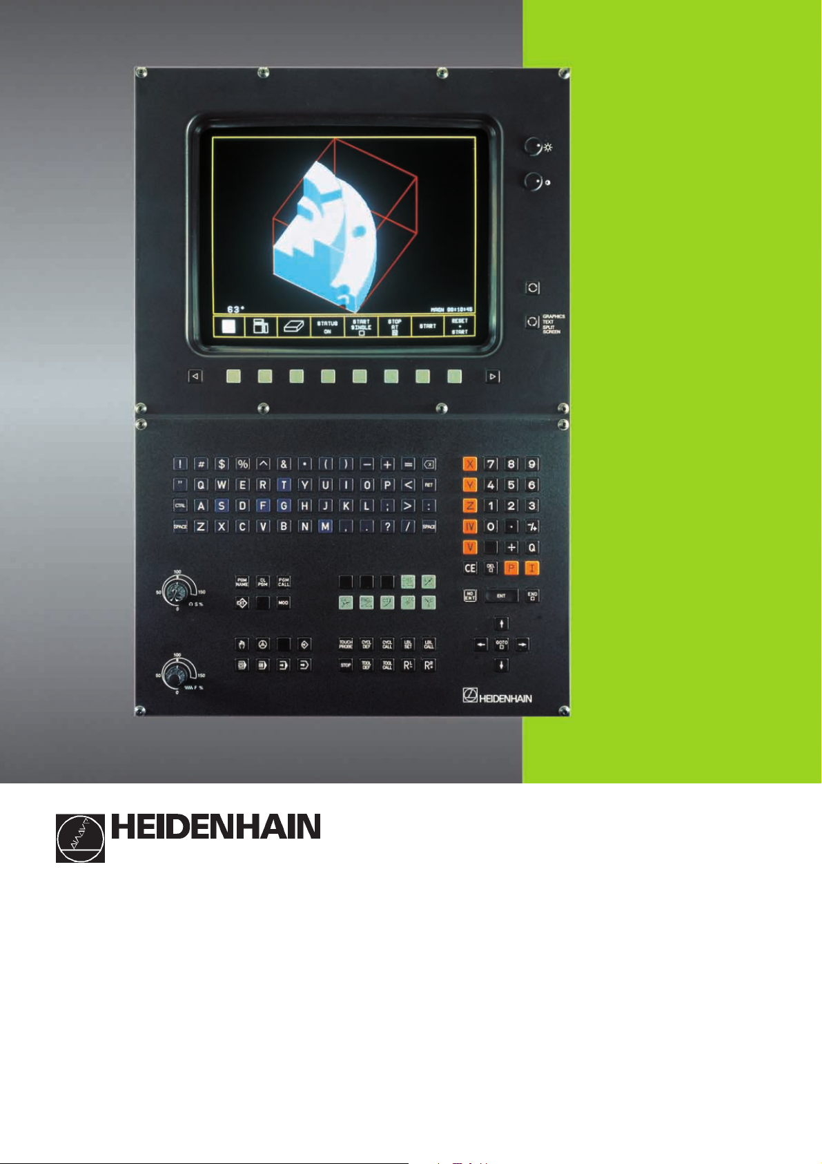
Controls on the TNC 426, TNC 425, TNC 415 B and
TNC 407
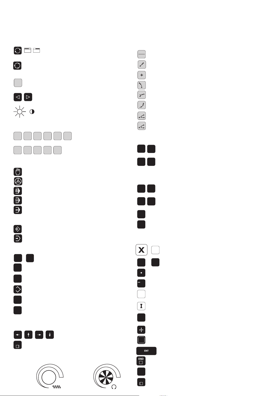
Controls on the visual display unit
Toggle display between machining and
programming modes
GRAPHICS
TEXT
SPLIT
SCREEN
Split screen layout
Soft keys for selecting functions in screen
Shift keys for the soft keys
Brightness, contrast
Typewriter keyboard for entering letters and symbols
Q
W
E
R
G F S T
T
M
Y
...
File names/
comments
ISO
programming
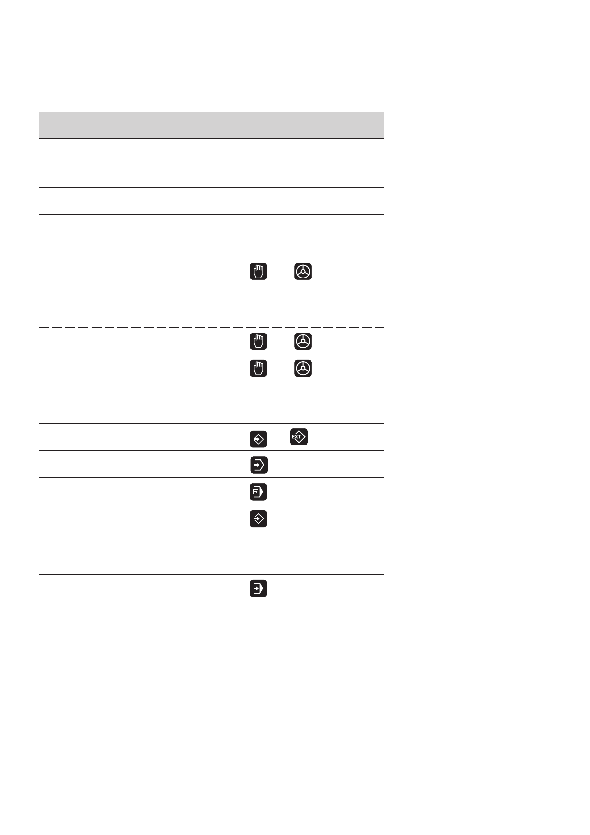
Machine operating modes
MANUAL OPERATION
EL. HANDWHEEL
POSITIONING WITH MDI
PROGRAM RUN/SINGLE BLOCK
PROGRAM RUN/FULL SEQUENCE
Programming modes
PROGRAMMING AND EDITING
Programming path movements
(conversational programming only)
APPR
DEP
L
CC
C
CR
CT
CHF
RND
Tool functions
TOOL
TOOL
DEF
CALL
R
R
R
+
Approach/depart contour
Straight line
Circle center/pole for polar coordinates
Circle with center
Circle with radius
Tangential circle
Chamfer
Corner rounding
(conversational programming only)
Enter or call tool length and radius
L
Activate tool radius compensation
-
(not on TNC 426)
Cycles, subprograms and program section repeats
(conversational programming only)
CYCL
CYCL
DEF
LBL
SET
STOP
TOUCH
PROBE
CALL
LBL
CALL
Define and call cycles
Enter and call labels for subprogramming
and program section repeats
Enter program stop in a program
Enter touch probe functions in a program
TEST RUN
Program and file management
PGM
MGT
CL
PGM
PGM
CALL
EXT
MOD
CALC
PGM
NAME
Select programs and files
Delete programs and files
Enter program call in a program
External data transfer
(not on TNC 426)
MOD functions
Pocket calculator
(TNC 426 only)
Moving the cursor and going directly to
blocks, cycles and parameter functions
Move the cursor (highlight)
GOTO
Go directly to blocks, cycles and
parameter functions
Override control knobs
100
Feed rate Spindle speed
50
1
50
0
F %
50
(not on TNC 426)
100
1
0
S %
Coordinate axes and numbers, editing
...
...
0
Select coordinate axes or enter
V
them into a program
Numbers
9
Decimal point
/
+
P
Arithmetic sign
Polar coordinates
Incremental dimensions
Q parameters for part families or
Q
mathematicalfunctions
Capture actual position
NO
ENT
Skip dialog questions, delete words
Confirm entry and resume dialog
End block
Clear numerical entry or TNC message
Abort dialog, delete program sections
50
CE
DEL
Page 3
TNC Guideline
From the workpiece drawing to
program-controlled machining
Step Task TNC operating Section in
mode manual
Preparation
1 Select tools —— ——
2 Set workpiece datum for
coordinate system —— ——
3 Determine spindle speeds
and feed rates —— ——
4 Switch on the machine —— 1.3
5 Cross over reference marks 1.3, 2.1
6 Clamp workpiece —— ——
7 Set datum /
Reset position display ...
7a ... with 3D touch probe 2.5
or
or
7b ... without
Entering and testing part programs
8 Enter part program or download
over external data interface 5 to 8, 9
9 Test part program for errors
10 Test run: Run the program
block by block without tool 3.2
11 Optimize the part program
(if necessary) 5 to 8
Machining the workpiece
12 Insert tool and run program 3.2
3D touch probe 2.3
or
or
3.1
Page 4

How to use this manual
This manual describes functions and features available on TNCs as of the following NC software numbers:
TNC 407 280 580 04
TNC 415 B, TNC 425 280 540 04
TNC 415 F, TNC 425 E 280 560 04
TNC 426 CA, TNC 426 PA 280 462 01
TNC 426 CE, TNC 426 PE 280 482 01
The suffixes E and F indicate export versions of the TNC.
The export versions TNC 415 F, TNC 425 E, TNC 426 CE, and
TNC 426 PE have the following limitations:
• Input and machining accuracy are limited to 1 µm
• Simultaneous linear movement in up to 4 axes
Some of the functions described in this manual are not available on all
TNCs. These functions are marked with symbols:
NC Software No.
407
415
425
426
The machine manufacturer adapts the features offered by the TNC to the
capabilities of the specific machine tool by setting machine parameters.
This means that not every machine tool will have all of the functions
described in this manual.
Some of the TNC functions which are not available on every machine are:
• Probe functions for the 3D touch probe
• Digitizing option
• Measuring tools with the TT 120 touch probe
• Rigid tapping
• Re-approaching a contour after an interruption
Your machine manual provides more detailed information. If you think a
function may be unavailable because of a defect, please contact the
machine tool builder.
Many machine manufacturers and HEIDENHAIN offer programming
courses for the TNCs. We recommend these courses as an effective way
of improving your programming skill and sharing information and ideas with
other TNC users.
Function not available on the TNC 407
Function not available on the TNC 415
Function not available on the TNC 425
Function not available on the TNC 426
(conversational programming only)
(conversational programming only)
TNC 426/TNC 425/TNC 415 B/TNC 407
Page 5

This manual is intended both for the TNC beginner and the TNC expert.
The TNC beginner can use it as a step-by-step workbook. The manual
begins with an explanation of the basics of numerical control (NC) and
provides a glimpse into their application in the TNC. It then introduces
the technique of conversational programming. All of the examples can
be practiced directly on the TNC. Each function is explained thoroughly
when it is used for the first time.
The TNC beginner should work through this manual completely from
beginning to end to ensure that he is capable of fully exploiting the
features of this powerful tool.
The TNC expert can use the manual as a comprehensive review and
reference work. The table of contents and numerous cross references
help him quickly find the topics and information he needs. Easy-to-read
dialog flowcharts show him how to enter data for the desired function.
The dialog flowcharts aid the beginner by providing a description of the
function of each key in a box to its right. If the user already knows the
keys, he can concentrate on the illustrated input overview at the left of
the flowchart. The TNC dialog messages are represented in shaded
boxes above the answering input sequence.
TNC 426/TNC 425/TNC 415 B/TNC 407
Page 6
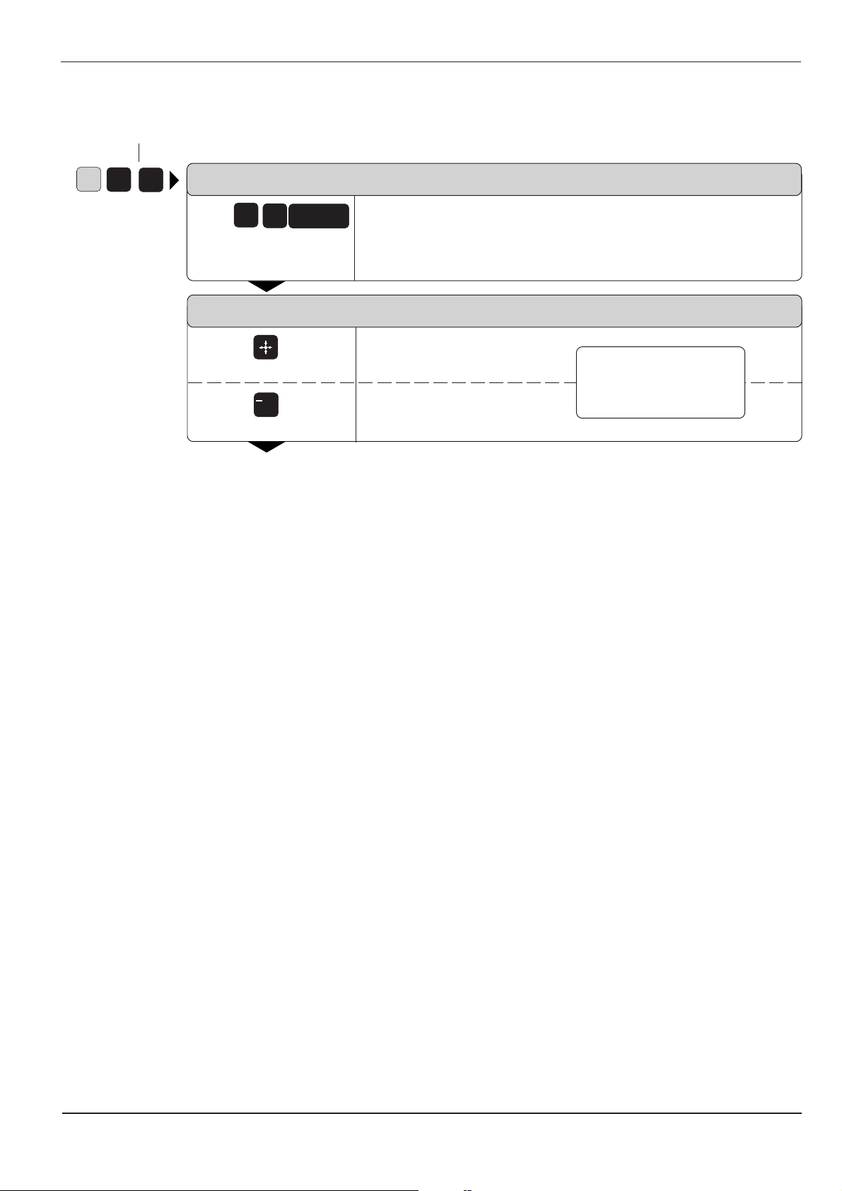
Layout of the dialog flowcharts
Dialog initiation key
G
8
3
DIALOG PROMPT (ON THE TNC SCREEN)
3
8
e.g.
Answer the prompt with
these keys
NEXT DIALOG PROMPT
Press this key
/
Or this key
ENT
+
Here the manual explains the function of the keys.
Function of the key
Function of the alternative key
.
.
The trail of points means that:
.
• the dialog is not completely illustrated, or
• the dialog continues on the next page.
Abbreviated dialog flowcharts
In abbreviated flowcharts an arrow (➤) is used to indicate new entries or
work steps.
A broken line indicates that
either the key above it or
below it can be pressed.
TNC 426/TNC 425/TNC 415 B/TNC 407
Page 7

Contents User's Manual TNC 407, TNC 415 B, TNC 425, TNC 426
(280 5x0-xx, 280 462-xx)
ISO Programming
Introduction
Manual Operation and Setup
Test Run and Program Run
Programming
Programming Tool Movements
Subprograms and Program Section Repeats
Programming with Q Parameters
Cycles
External Data Transfer
MOD-Functions
Tabels, Overviews and Diagrams
1
2
3
4
5
6
7
8
9
10
11
Page 8

1 Introduction
1.1 The TNC 400 Series ............................................................................1-2
Keyboard........................................................................................................................ 1-4
Visual display unit .......................................................................................................... 1-5
TNC Accessories ........................................................................................................... 1-9
1.2 Fundamentals of NC.........................................................................1-10
Introduction .................................................................................................................. 1-10
What is NC? ................................................................................................................. 1-10
The part program .........................................................................................................1-10
Programming ............................................................................................................... 1-10
Reference system ........................................................................................................ 1-11
Cartesian coordinate system ....................................................................................... 1-11
Additional axes............................................................................................................. 1-12
Polar coordinates ......................................................................................................... 1-12
Setting the pole ............................................................................................................ 1-13
Datum setting ............................................................................................................... 1 -13
Absolute workpiece positions .......................................................................................1-15
Incremental workpiece positions .................................................................................. 1-15
Programming tool movements ..................................................................................... 1-18
Position encoders ........................................................................................................ 1-18
Reference marks......................................................................................................... 1-18
1.3 Switch-On ..........................................................................................1-19
1.4 Graphics and Status Displays .........................................................1-20
Graphics during program run ....................................................................................... 1-20
Plan view...................................................................................................................... 1-21
Projection in 3 planes................................................................................................... 1-22
Cursor position during projection in 3 planes ...............................................................1-23
3D view ........................................................................................................................ 1-23
Magnifying details ........................................................................................................ 1-25
Repeating graphic simulation....................................................................................... 1-26
Measuring the machining time ..................................................................................... 1-26
Status displays ............................................................................................................. 1-27
Additional status displays............................................................................................. 1-27
1.5 File Management on the TNC 426 ...................................................1-30
Data security ................................................................................................................1-30
Calling the file manager ............................................................................................... 1-31
Functions for file management..................................................................................... 1-35
Selecting file types .......................................................................................................1-36
To copy individual files .................................................................................................1-36
To copy several files into another directory ................................................................. 1-37
To erase a file ..............................................................................................................1-38
To rename a file ...........................................................................................................1-38
To protect a file ............................................................................................................ 1-38
To cancel file protection ...............................................................................................1-38
To convert a file ........................................................................................................... 1-39
TNC 426/TNC 425/TNC 415 B/TNC 407
Page 9

1.6 File Management on the TNC 425, TNC 415 B and TNC 407 ........1-40
File directory ................................................................................................................ 1-40
File status..................................................................................................................... 1-41
Selecting a file.............................................................................................................. 1-41
To copy a file................................................................................................................ 1-42
To erase a file ..............................................................................................................1-42
To rename a file ...........................................................................................................1-42
To protect a file ............................................................................................................ 1-42
To cancel file protection ...............................................................................................1-42
To convert a file ........................................................................................................... 1-43
File management for files on external data media .......................................................1-43
TNC 426/TNC 425/TNC 415 B/TNC 407
Page 10

2 Manual Operation and Setup
2.1 Moving the Machine Axes...................................................................2-2
Traversing with the machine axis direction buttons................................................... 2-2
Traversing with an electronic handwheel .................................................................. 2-3
Using the HR 330 electronic handwheel ................................................................... 2-3
Incremental jog positioning........................................................................................ 2-4
Positioning with manual data input (MDI) ..................................................................2-4
2.2 Spindle Speed S, Feed Rate F and Miscellaneous Functions M.....2-5
To enter the spindle speed S .................................................................................... 2-5
To change the spindle speed S ................................................................................. 2-5
To change the feed rate F .........................................................................................2-6
To enter a miscellaneous function M......................................................................... 2-6
2.3 Setting the Datum Without a 3D Touch Probe ..................................2-7
Setting the datum in the tool axis .............................................................................. 2-7
To set the datum in the working plane ...................................................................... 2-8
2.4 3D Touch Probes .................................................................................2-9
3D Touch probe applications..................................................................................... 2-9
To select the touch probe functions ..........................................................................2-9
Calibrating the 3D touch probe................................................................................ 2-10
Compensating workpiece misalignment .................................................................. 2-12
2.5 Setting the Datum with a 3D Touch Probe ......................................2-14
To set the datum in an axis ..................................................................................... 2-14
Corner as datum ......................................................................................................2-15
Circle center as datum ............................................................................................ 2-17
2.6 Measuring with a 3D Touch Probe ...................................................2-20
To find the coordinates of a position on an aligned workpiece................................ 2-20
Finding the coordinates of a corner in the working plane ........................................ 2-20
Measuring workpiece dimensions ........................................................................... 2-21
Measuring angles ....................................................................................................2-22
2.7 Tilting the Working Plane .................................................................2-24
Traversing reference points with tilted axes ............................................................ 2-25
Setting the datum in a tilted coordinate system....................................................... 2-25
Position display in the tilted system......................................................................... 2-25
Limitations on working with the tilting function ........................................................ 2-25
To activate manual tilting......................................................................................... 2-26
TNC 426/TNC 425/TNC 415 B/TNC 407
Page 11

3 Test Run and Program Run
3.1 Test Run ...............................................................................................3-2
To run a program test ................................................................................................3-2
To run a program test up to a certain block............................................................... 3-3
The display functions for test run .............................................................................. 3-3
3.2 Program Run ........................................................................................ 3-4
To run a part program ............................................................................................... 3-4
Interrupting machining ............................................................................................... 3-5
Moving machine axes during an interruption............................................................. 3-6
Resuming program run after an interruption ............................................................. 3-6
Mid-program startup .................................................................................................. 3-8
Returning to the contour ............................................................................................ 3-9
3.3 Optional Block Skip...........................................................................3-10
3.4 Blockwise Transfer: Testing and Running Long Programs .......... 3-11
TNC 426/TNC 425/TNC 415 B/TNC 407
Page 12

4 Programming
4.1 Creating Part Programs ......................................................................4-2
Layout of a program .................................................................................................. 4-2
Editing functions ........................................................................................................ 4-3
4.2 Tools .....................................................................................................4-5
Setting the tool data .................................................................................................. 4-5
Oversizes for lengths and radii: delta values ............................................................ 4-6
Entering tool data into the program ........................................................................... 4-7
Entering tool data in tables ........................................................................................4-8
Tool data in tables ...................................................................................................4-10
Pocket table for tool changer................................................................................... 4-14
Calling tool data .......................................................................................................4-15
Tool change .............................................................................................................4-15
Automatic tool change: M101 .................................................................................. 4-16
4.3 Tool Compensation Values ..............................................................4-17
Effect of tool compensation values.......................................................................... 4-17
Tool radius compensation .......................................................................................4-17
Machining corners ................................................................................................... 4-19
4.4 Program Creation ..............................................................................4-20
Defining the blank form ........................................................................................... 4-20
To create a new part program .................................................................................4-21
4.5 Entering Tool-Related Data ..............................................................4-23
Feed rate F .............................................................................................................. 4-23
Spindle speed S ......................................................................................................4-24
4.6 Entering Miscellaneous Functions and Program Stop ..................4-25
4.7 Actual Position Capture ....................................................................4-26
4.8 Integrated Pocket Calculator ............................................................4-27
4.9 Marking Blocks for Optional Block Skip .........................................4-28
4.10 Text Files ............................................................................................4-29
Finding text sections ................................................................................................4-31
To erase and insert characters, words and lines..................................................... 4-32
Editing text blocks ...................................................................................................4-33
4.11 Creating Pallet Files ..........................................................................4-35
4.12 Adding Comments to the Program ..................................................4-37
Adding comments to program blocks ...................................................................... 4-37
TNC 426/TNC 425/TNC 415 B/TNC 407
Page 13

5 Programming Tool Movements
5.1 General Information on Programming Tool Movements .................5-2
5.2 Contour Approach and Departure .....................................................5-4
Starting point and end point ...................................................................................... 5-4
Tangential approach and departure ..........................................................................5-6
5.3 Path Functions..................................................................................... 5-7
General information ...................................................................................................5-7
Machine axis movement under program control ....................................................... 5-7
Overview of path functions ........................................................................................ 5-9
5.4 Path Contours – Cartesian Coordinates .........................................5-10
G00: Straight line with rapid traverse ...................................................................... 5-10
G01: Straight line with feed rate F ... .......................................................................5-10
G24: Chamfer .......................................................................................................... 5-13
Circles and circular arcs .......................................................................................... 5-15
Circle center I, J, K ..................................................................................................5-16
G02/G03/G05: Circular path around pole I, J, K ..................................................... 5-18
G02/G03/G05: Circular path with defined radius..................................................... 5-21
G06: Circular path with tangential connection ......................................................... 5-24
G25: Corner rounding.............................................................................................. 5-26
5.5 Path Contours – Polar Coordinates .................................................5-28
Polar coordinate origin: Pole I, J, K .........................................................................5-28
G10: Straight line with rapid traverse ..................................................................... 5-28
G11: Straight line with feed rate F … ...................................................................... 5-28
G12/G13/G15: Circular path around pole I, J, K ..................................................... 5-30
G16: Circular path with tangential transition ............................................................5-32
Helical interpolation .................................................................................................5-33
5.6 M Functions for Contouring Behavior and Coordinate Data ........5-36
Smoothing corners: M90 ......................................................................................... 5-36
Machining small contour steps: M97 ....................................................................... 5-37
Machining open contours: M98 ............................................................................... 5-38
Programming machine-referenced coordinates: M91/M92 ..................................... 5-39
Feed rate factor for plunging movements: M103 F… .............................................. 5-40
Feed rate at circular arcs: M109/M110/M111.......................................................... 5-41
Insert rounding arc between straight lines: M112 E... ............................................. 5-41
Automatic compensation of machine geometry when working with
tilted axes: M114 ..................................................................................................... 5-42
Feed rate in mm/min on rotary axes A, B, C: M116 ................................................ 5-43
Reduce display of a rotary axis to a value less than 360°: M94.............................. 5-43
Optimized traverse of rotary axes: M126 ................................................................5-44
5.7 Positioning with Manual Data Input: System File $MDI .................5-45
TNC 426/TNC 425/TNC 415 B/TNC 407
Page 14

6 Subprograms and Program Section Repeats
6.1 Subprograms .......................................................................................6-2
Operating sequence ..................................................................................................6-2
Operating limitations .................................................................................................. 6-2
Programming and calling subprograms .....................................................................6-3
6.2 Program Section Repeats ................................................................... 6-5
Operating sequence ..................................................................................................6-5
Programming notes ................................................................................................... 6-5
Programming and executing a program section repeat ............................................ 6-5
6.3 Program as Subprogram .................................................................... 6-8
Operating sequence ..................................................................................................6-8
Operating limitations .................................................................................................. 6-8
Calling a program as a subprogram ..........................................................................6-8
6.4 Nesting .................................................................................................6-9
Nesting depth ............................................................................................................ 6-9
Subprogram within a subprogram ............................................................................. 6-9
Repeating program section repeats ........................................................................ 6-11
Repeating subprograms ..........................................................................................6-12
TNC 426/TNC 425/TNC 415 B/TNC 407
Page 15

7 Programming with Q Parameters
7.1 Part Families — Q Parameters in Place of Numerical Values .........7-4
7.2 Describing Contours Through Mathematical Functions .................7-7
Overview ................................................................................................................... 7-7
7.3 Trigonometric Functions ..................................................................7-10
Overview ................................................................................................................. 7-10
7.4 If-Then Decisions with Q Parameters ..............................................7-11
Jumps ..................................................................................................................7-11
Overview ................................................................................................................. 7-11
7.5 Checking and Changing Q Parameters ...........................................7-13
7.6 Diverse Functions .............................................................................7-14
Displaying error messages ...................................................................................... 7-14
Output through an external data interface ...............................................................7-16
Formatted output of texts and Q parameter values .................................................7-17
Reading system data............................................................................................... 7-18
Transfer to the PLC .................................................................................................7-19
7.7 Entering Formulas Directly...............................................................7-20
Overview of functions .............................................................................................. 7-20
7.8 Measuring with the 3D Touch Probe During Program Run ...........7-23
7.9 Programming Examples ...................................................................7-25
Rectangular pocket with island, corner rounding and tangential approach ............. 7-25
Bolt hole circles ....................................................................................................... 7-27
Ellipse .................................................................................................................. 7-29
Hemisphere machined with end mill ........................................................................7-31
TNC 426/TNC 425/TNC 415 B/TNC 407
Page 16

8 Cycles
8.1 General Overview of Cycles ...............................................................8-2
8.2 Simple Fixed Cycles ............................................................................8-4
8.3 SL Cycles (Group I) ...........................................................................8-17
8.4 SL Cycles (Group II) ..........................................................................8-31
Programming a cycle................................................................................................. 8-2
Dimensions in the tool axis........................................................................................ 8-3
PECKING (G83) ........................................................................................................ 8-4
TAPPING with floating tap holder (G84) ................................................................... 8-6
RIGID TAPPING (G85) ............................................................................................. 8-8
THREAD CUTTING (G86) ........................................................................................ 8-9
SLOT MILLING (G74) .............................................................................................8-11
POCKET MILLING (G75/G76) ................................................................................ 8-13
CIRCULAR POCKET MILLING (G77/G78) ............................................................. 8-15
CONTOUR GEOMETRY (G37) .............................................................................. 8-18
ROUGH-OUT (G57) ................................................................................................8-19
Overlapping contours .............................................................................................. 8-21
PILOT DRILLING (G56) .......................................................................................... 8-27
CONTOUR MILLING (G58/G59) ............................................................................. 8-28
CONTOUR DATA (G120) .......................................................................................8-32
PILOT DRILLING (G121) ........................................................................................ 8-33
ROUGH-OUT (G122) .............................................................................................. 8-34
FLOOR FINISHING (G123)..................................................................................... 8-34
SIDE FINISHING (G124) .........................................................................................8-35
CONTOUR TRAIN (G125) ...................................................................................... 8-37
CYLINDER SURFACE G127 .................................................................................. 8-39
8.5 Coordinate Transformations ............................................................8-42
DATUM SHIFT (G54) .............................................................................................. 8-43
DATUM SHIFT with datum tables (G53) .................................................................8-45
MIRROR IMAGE (G28) ...........................................................................................8-48
ROTATION (G73) .................................................................................................... 8-50
SCALING FACTOR (G72)....................................................................................... 8-51
8.6 Other Cycles ......................................................................................8-53
DWELL TIME (G04) ................................................................................................8-53
PROGRAM CALL (G39).......................................................................................... 8-53
ORIENTED SPINDLE STOP (G36) ........................................................................ 8-54
WORKING PLANE (G80) ........................................................................................ 8-55
TNC 426/TNC 425/TNC 415 B/TNC 407
Page 17

9 External Data Transfer
9.1 Data Transfer with the TNC 426 .........................................................9-2
To copy individual files into the TNC .........................................................................9-2
To copy multiple files into the TNC ............................................................................9-3
Copying files out of the TNC ..................................................................................... 9-3
9.2 Data Transfer with the TNC 425, TNC 415 B and TNC 407...............9-4
Selecting and transferring files .................................................................................. 9-5
Blockwise transfer ..................................................................................................... 9 -6
9.3 Pin Layout and Connecting Cable for the Data Interfaces ..............9-7
RS-232-C/V.24 Interface ........................................................................................... 9-7
RS-422/V.11 Interface ............................................................................................... 9-9
9.4 Preparing the Devices for Data Transfer .........................................9-10
HEIDENHAIN devices .............................................................................................9-10
Non-HEIDENHAIN devices ..................................................................................... 9-10
TNC 426/TNC 425/TNC 415 B/TNC 407
Page 18

10 MOD Functions
10.1 Selecting, Changing and Exiting the MOD Functions ...................10-3
10.2 Software Numbers and Option Numbers ........................................10-3
10.3 Code Numbers ...................................................................................10-3
10.4 Setting the External Data Interfaces ................................................10-4
Setting the RS-232 interface ................................................................................... 10-4
Setting the RS-422 interface ................................................................................... 10-4
Selecting the OPERATING MODE.......................................................................... 10-4
Setting the BAUD RATE ..........................................................................................10-4
ASSIGN .................................................................................................................. 10-5
10.5 Machine-Specific User Parameters..................................................10-6
10.6 Showing the Workpiece in the Working Space ..............................10-6
Overview of functions .............................................................................................. 10-7
10.7 Position Display Types .....................................................................10-8
10.8 Unit of Measurement ......................................................................... 10-9
10.9 Programming Language for $MDI....................................................10-9
10.10 Selecting the Axes for Generating L Blocks
(conversational programming only) ................................................10-9
10.11 Axis Traverse Limits .......................................................................10-10
10.12 HELP files .........................................................................................10-11
TNC 426/TNC 425/TNC 415 B/TNC 407
Page 19

11 Tables, Overviews and Diagrams
11.1 General User Parameters..................................................................11-2
Input possibilities for machine parameters .............................................................. 11-2
Selecting general user parameters ......................................................................... 11-2
External data transfer ..............................................................................................11-3
3D touch probes and digitizing ................................................................................11-4
TNC displays, TNC editor........................................................................................ 11-7
Machining and program run .................................................................................. 11-13
Electronic handwheel ............................................................................................ 11-15
11.2 Miscellaneous Functions (M Functions) .......................................11-16
Miscellaneous functions with predetermined effect ............................................... 11-16
Vacant miscellaneous functions ............................................................................11-18
11.3 Preassigned Q Parameters .............................................................11-19
11.4 Features, Specifications and Accessories....................................11-21
Accessories ........................................................................................................... 11-24
11.5 TNC Error Messages .......................................................................11-26
TNC error messages during programming ............................................................ 11-26
TNC error messages during test run and program run .........................................11-27
11.6 Address Letters (ISO)......................................................................11-31
Parameter definitions ............................................................................................ 11-34
TNC 426/TNC 425/TNC 415 B/TNC 407
Page 20

1 Introduction
1.1 The TNC 400 Series
The TNCs are shop-floor programmable contouring controls for boring
machines, milling machines and machining centers with up to 5 axes.
They also feature oriented spindle stop.
Two operating modes are always active simultaneously: one for machine
movements (machining modes) and one for programming or program
testing (programming modes).
TNC 426
The TNC 426 PA features digital control of machine axis speed. This
provides high geometrical accuracy, even with complex workpiece
surfaces and at high machining speeds.
An integrated 170 megabyte hard disk provides storage for programs that
were created on external devices. The TNC 426 also offers an on-screen
pocket calculator.
TNC 425
The TNC 425 also features digital control of machine axis speed. This
results in high geometrical accuracy, even with complex workpiece
surfaces and at high machining speeds.
TNC 415 B
The TNC 415 B uses an analog method of speed control in the drive
amplifier. All the programming and machining functions of the TNC 425
are also available on the TNC 415 B.
TNC 407
The TNC 407 uses an analog method of speed control in the drive
amplifier. Some functions are not available on the TNC 407, such as:
• Graphics during program run
• Tilting the machining plane
• Linear movement in more than three axes
Technical differences between the TNCs
TNC 426 PA TNC 426 CA TNC 425 TNC 415 B TNC 407
Speed control Digital Analog Digital/analog Analog Analog
Block processing time 4 ms 4 ms 4 ms 4 ms 24 ms
Control loop cycle time:
Contouring interpolation 3 ms 3 ms 3 ms 2 ms 6 ms
Control loop cycle time:
Fine interpolation 0.6 ms --- 0.6 ms 0.6 ms --Program memory 170 M byte 170 M byte 256 K byte 256 K byte 128 K byte
(hard disk) (hard disk)
Input resolution 0.1 µm 0.1 µm 0.1 µm 0.1 µm 1 µm
TNC 426/TNC 425/TNC 415 B/TNC 4071-2
Page 21

1 Introduction
1.1 The TNC 400 Series
Visual display unit and keyboard
The 14-inch color monitor displays all the information necessary for
effective use of the TNC's capabilities.
The keys are grouped on the keyboard according to function. This makes it
easier to create programs and to use the TNC’s functions.
Programming
The TNCs are programmed in ISO format.
It is also possible to program in easy-to-understand HEIDENHAIN
conversational format (a separate User's Manual is available for this).
Graphics
Workpiece machining can be graphically simulated both during machining
(except on TNC 407) or before actual machining. Various display modes are
available.
Compatibility
The TNCs can execute all part programs written on HEIDENHAIN
TNC 150 B controls or later.
TNC 426/TNC 425/TNC 415 B/TNC 407 1-3
Page 22
1 Introduction
1.1 The TNC 400 Series
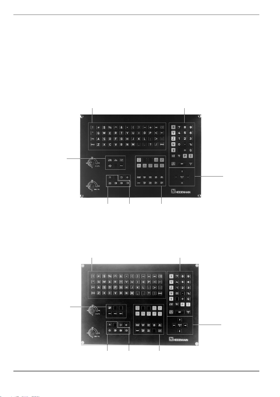
Keyboard
The keys on the TNC keyboard are marked with symbols and abbreviations that make them easy to remember. They are grouped according to
the their functions. The functions of the individual keys are described in the
front cover fold-out of the TNC user's manual. A description of machine
panel buttons is provided in the manual for your machine tool.
The keyboard of TNC 407, TNC 415 and TNC 425 controls
Typewriter-style keyboard for entering
file names, comments and other texts,
as well as programming in ISO format
Numerical input and axis selection
Program and file
management
Machine
operating
modes
The keyboard of TNC 426 controls
Typewriter-style keyboard for entering
file names, comments and other texts,
as well as programming in ISO format
Programming
modes
Arrow keys and
GOTO key
Dialog initiation for
conversational
programming
Numerical input and axis selection
File management,
pocket calculator,
MOD functions,
HELP functions
Machine
operating
modes
Programming
modes
Arrow keys and
GOTO key
Dialog initiation
TNC 426/TNC 425/TNC 415 B/TNC 4071-4
Page 23
1 Introduction
1.1 The TNC 400 Series
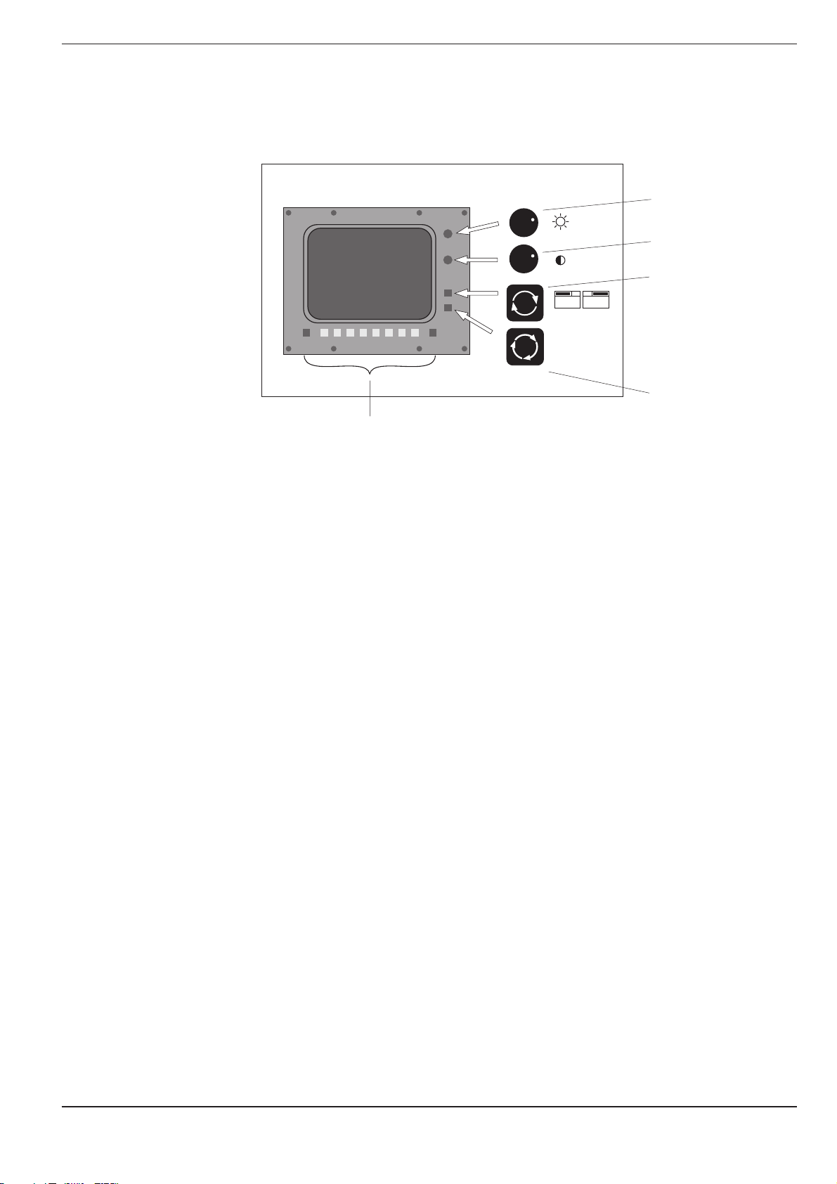
Visual display unit
Soft keys with context-specific
functions, and two shift keys
for additional soft-key rows
Brightness control
Contrast control
Switchover between
the active programming and machining
modes
GRAPHICS
TEXT
SPLIT
SCREEN
SPLIT SCREEN key
for switching screen
layout (see page 1-6)
Headline
The two selected TNC modes are shown in the screen headline:
the machining mode to the left and the programming mode to the right.
The currently active mode is displayed in the larger box, where dialog
prompts and TNC messages also appear.
Soft keys
The soft keys select the functions shown in the soft-key row immediately
above them. The shift keys to the right and left call up additional soft-key
rows. Colored lines above the soft-key row indicate the number of
available rows. The line representing the active row is highlighted.
TNC 426/TNC 425/TNC 415 B/TNC 407 1-5
Page 24
1 Introduction
1.1 The TNC 400 Series
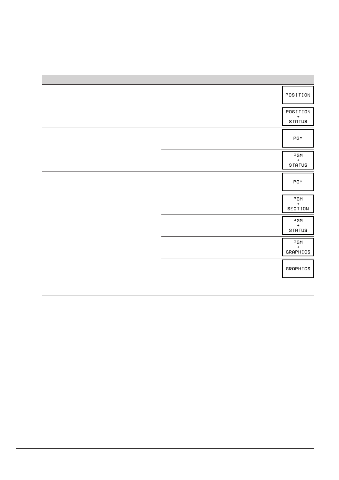
Screen layout
You can select the type of display on the TNC screen by pressing the
SPLIT SCREEN key and one of the soft keys listed below. Depending on
the active mode of operation, you can select:
Mode of operation Screen layout Soft key
MANUAL Positions
ELECTRONIC HANDWHEEL
POSITIONING WITH MDI Program blocks
PROGRAM RUN/FULL SEQUENCE Program blocks
PROGRAM RUN/SINGLE BLOCK
TEST RUN
Left: positions
Right: STATUS
Left: program blocks
Right: STATUS
Left: program blocks
Right: program structure
(
conversational programming only
Left: program blocks
Right: STATUS
)
Left: program blocks
Right: graphics
Graphics
PROGRAMMING AND EDITING No screen selection possible, the TNC
displays program blocks only
TNC 426/TNC 425/TNC 415 B/TNC 4071-6
Page 25
1 Introduction
1.1 The TNC 400 Series
Screen layout of modes
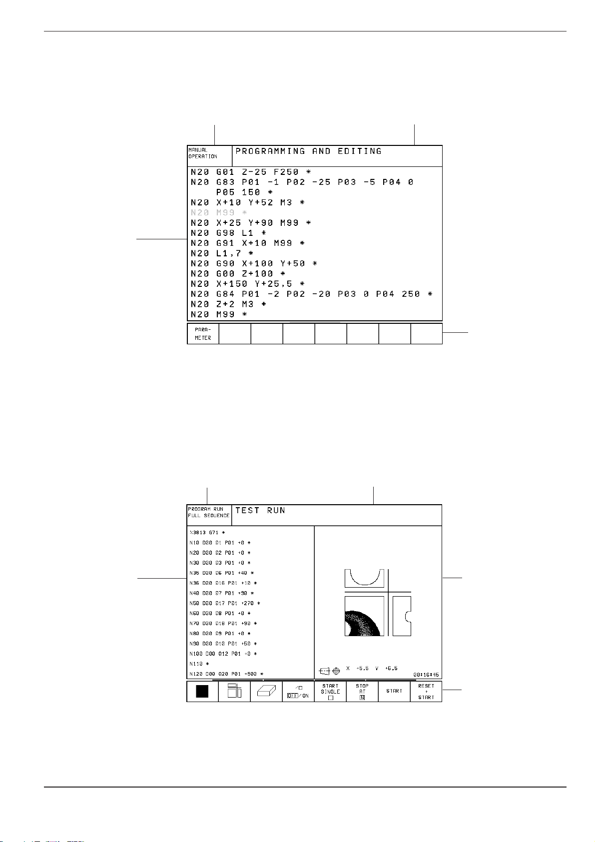
PROGRAMMING AND EDITING:
Text of the
selected
program
Machining
mode
Programming mode is selected
TEST RUN:
Text of the
selected
program
Machining
mode
Soft-key row
Programming mode is selected
Graphics
(or additional
status display)
Soft-key row
TNC 426/TNC 425/TNC 415 B/TNC 407 1-7
Page 26
1 Introduction
1.1 The TNC 400 Series
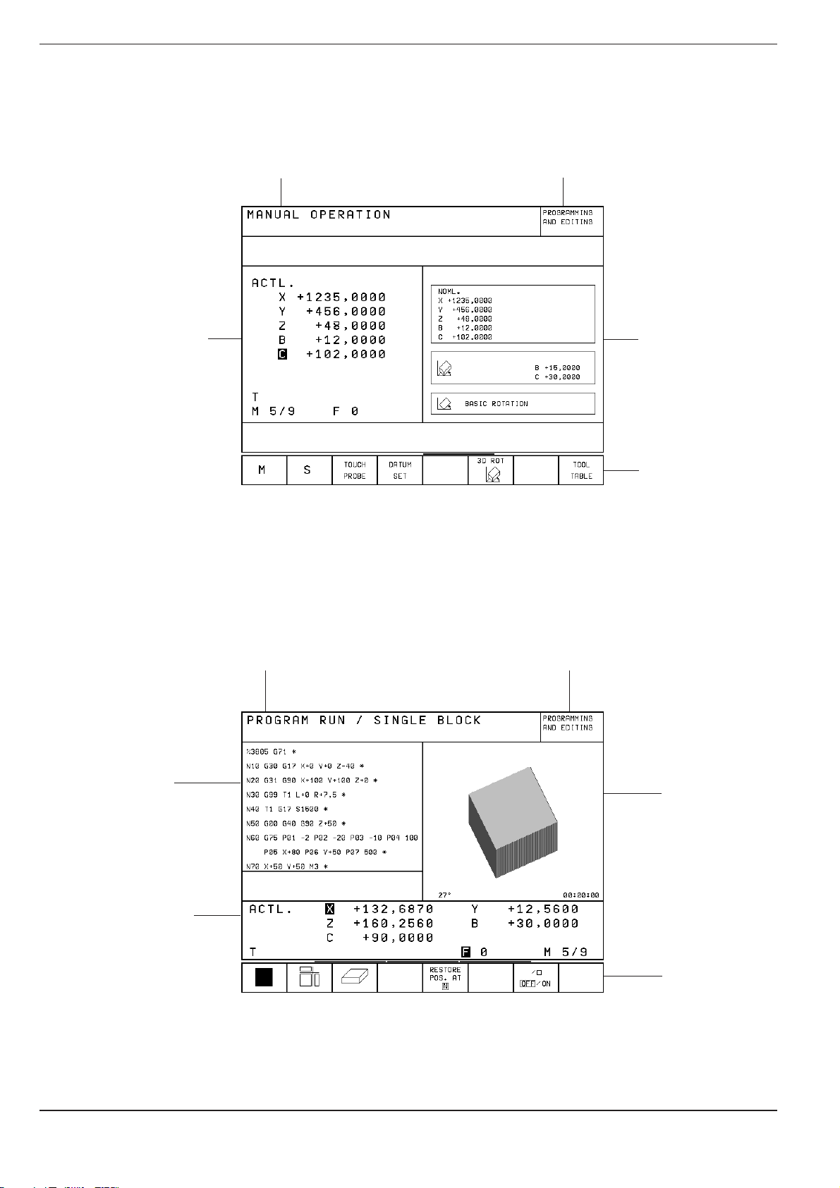
MANUAL OPERATION and ELECTRONIC HANDWHEEL modes:
• Coordinates
• Selected axis
• ❊ means TNC
in operation
• Status display,
e.g. feed rate F,
miscellaneous
function M,
symbols for basic
rotation and/or tilted
working plane
A machining mode is
selected
Programming
mode
Additional
status display
Soft-key row
PROGRAM RUN/FULL SEQUENCE, PROGRAM RUN/SINGLE BLOCK
A machining mode is
selected
Text of the
selected
program
Status display
Programming
mode
Graphics
(or additional
status display,
or program
structure)
Soft-key row
TNC 426/TNC 425/TNC 415 B/TNC 4071-8
Page 27
1 Introduction
1.1 The TNC 400 Series
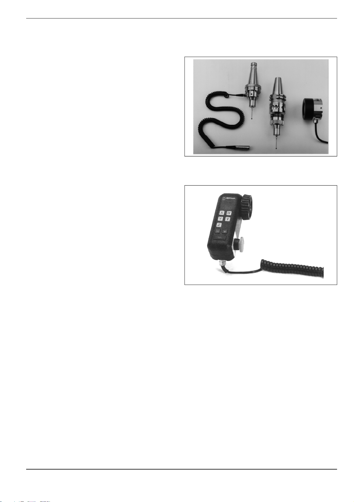
TNC Accessories
3D Touch Probe Systems
The TNC provides the following features when used
in conjunction with a HEIDENHAIN 3D touch probe:
• Electronic workpiece alignment (compensation
of workpiece misalignment)
• Datum setting
• Measurement of the workpiece during
program run
• Digitizing 3D surfaces (optional, only available
with conversational programming)
• Measuring tools with the TT 120 touch probe
(only available)
Fig. 1.6: TS 220 and TS 630 3D-touch probes
Electronic Handwheels
Electronic handwheels facilitate precise manual
control of the axis slides. Similar to a conventional
machine tool, the machine slide moves in direct
relation to the rotation of the handwheel. A wide
range of traverses per handwheel revolution is
available.
Portable handwheels such as the HR 330 are
connected via cable to the TNC. Integral handwheels such as the HR 130 are built into the
machine control panel. An adapter permits connection of up to three handwheels.
Your machine manufacturer can tell you more about
the handwheel configuration of your machine.
Fig. 1.7: HR 330 electronic handwheel
TNC 426/TNC 425/TNC 415 B/TNC 407 1-9
Page 28

1 Introduction
1.2 Fundamentals of NC
Introduction
This chapter discusses the following topics:
• What is NC?
• The part program
• Programming
• Reference system
• Cartesian coordinate system
• Additional axes
• Polar coordinates
• Setting the pole
• Datum setting
• Absolute workpiece positions
• Incremental workpiece positions
• Programming tool movements
• Position encoders
• Reference marks
What is NC?
NC stands for Numerical Control, that is, the operation of a machine tool
by a series of coded instructions comprised of numbers. Modern controls
such as the TNC have a built-in computer for this purpose and are therefore called CNC (Computerized Numerical Control).
The part program
The part program is a complete list of instructions for machining a part.
It contains such information as the target position of a tool movement, the
path function (how the tool should move toward the target position) and
the feed rate. Information on the radius and length of the tool, spindle
speed and tool axis must also be included in the program.
Programming
ISO programming is partially dialog-guided. The programmer is free to
enter the individual commands (words) in each block in any sequence
(except with G90/G91). The commands are automatically sorted by the
TNC when the block is concluded.
TNC 426/TNC 425/TNC 415 B/TNC 4071-10
Page 29
1 Introduction
0° 90°90°
0°
30°
30°
60°
60°
Greenwich
+X
+Y
+Z
+X
+Z
+Y
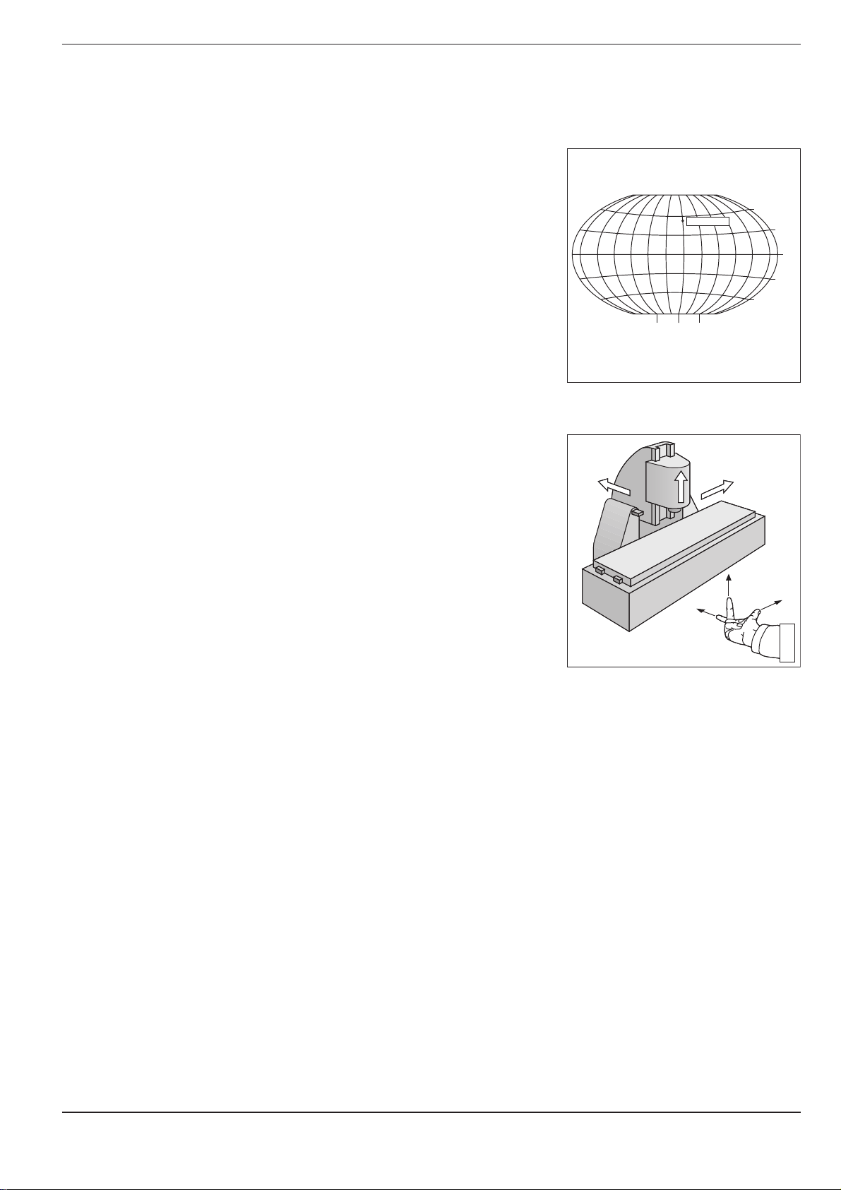
1.2 Fundamentals of NC
Reference system
In order to define positions, a reference system is necessary. For
example, positions on the earth's surface can be defined “absolutely” by
their geographic coordinates of longitude and latitude. The word
coordinate
network of horizontal and vertical lines around the globe constitute an
absolute reference system — in contrast to the relative definition of a
position that is referenced to a known location.
comes from the Latin word for “that which is arranged.” The
Cartesian coordinate system
On a TNC-controlled milling machine, workpieces are normally machined
according to a workpiece-based Cartesian coordinate system (a
rectangular coordinate system named after the French mathematician
and philosopher Renatus Cartesius, who lived from 1596 to 1650). The
Cartesian coordinate system is based on three coordinate axes X, Y and Z
which are parallel to the machine guideways.
The figure to the right illustrates the “right-hand rule” for remembering the
three axis directions: the middle finger is pointing in the positive direction
of the tool axis from the workpiece toward the tool (the Z axis), the thumb
is pointing in the positive X direction, and the index finger in the positive Y
direction.
Fig. 1.8: The geographic coordinate system
is an absolute reference system
Fig. 1.9: Designations and directions of the
axes on a milling machine
TNC 426/TNC 425/TNC 415 B/TNC 407 1-11
Page 30
1 Introduction
1.2 Fundamentals of NC
Additional axes
The TNC can control the machine in more than three axes. Axes U, V and
W are secondary linear axes parallel to the main axes X, Y and Z, respec-
tively (see illustration). Rotary axes
as A, B and C.
are also possible, and are designated
W+
Z
Y
C+
B+
V+
A+
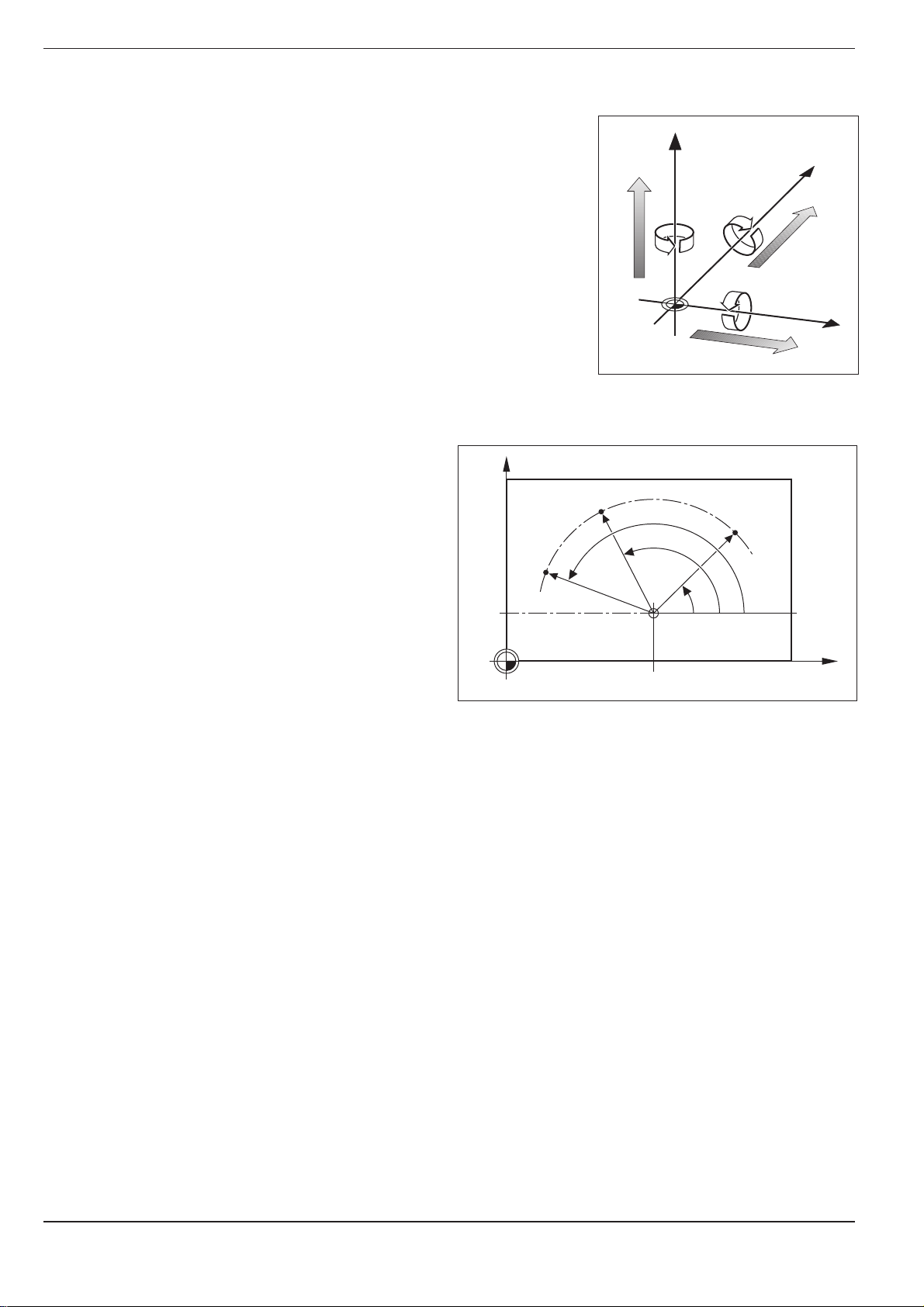
Polar coordinates
Although the Cartesian coordinate system is
especially useful for parts whose dimensions are
mutually perpendicular, in the case of parts containing circular arcs or angles it is often simpler to give
the dimensions in polar coordinates. While Cartesian coordinates are three-dimensional and can
describe points in space, polar coordinates are twodimensional and describe points in a plane.
Polar coordinates have their datum at a pole I, J, K
from which a position is measured in terms of its
distance from the pole and the angle of its position
in relation to the pole.
You could think of polar coordinates as the result of
a measurement using a scale whose zero point is
fixed at the datum and which you can rotate to
different angles in the plane around the pole.
The positions in this plane are defined by the
U+
Fig. 1.10: Direction and designation of
additional axes
Y
R
X
H
3
R
J = 10
Fig. 1.11: Identifying positions on a circular arc with polar coordinates
H
I = 30
R
2
H
1
0
°
X
• Polar Radius R, the distance from the circle
center I, J to the position, and the
• Polar Angle H, the size of the angle between
the reference axis and the scale.
TNC 426/TNC 425/TNC 415 B/TNC 4071-12
Page 31

1 Introduction
Y
X
Z
1.2 Fundamentals of NC
Setting the pole
The pole is set by entering two Cartesian coordinates. These coordinates
also determine the reference axis for the polar angle H.
Coordinates of the pole Angle reference axis
I J +X
J K +Y
K I +Z
Z
Z
Y
+
J
I
Fig. 1.12: Polar coordinates and their associated reference axes
Datum setting
The workpiece drawing identifies a certain point on the workpiece (usually
a corner) as the “absolute datum” and perhaps one or more other points
as relative datums. The datum setting procedure establishes these points
as the origin of the absolute or relative coordinate system. The
workpiece, which is aligned with the machine axes, is moved to a certain
position relative to the tool and the display is set either to zero or to
another appropriate value (e.g., to compensate the tool radius).
0°
X
K
J
+
Z
Y
Y
0°
0°
+
K
X
I
X
Fig. 1.13: The workpiece datum represents
the origin of the Cartesian
coordinate system
TNC 426/TNC 425/TNC 415 B/TNC 407 1-13
Page 32

1 Introduction
Y
X
Z
1
10
5
1.2 Fundamentals of NC
Example:
Drawing with several relative datums
(ISO 129 or DIN 406 Part 11, fig. 171)
1225
750
320
125
250
216,5
216,5
250
-250
-125
-216,5
0
125
0
-125
-216,5
-250
150
0
-150
300±0,1
0
0
0
325
450
700
900
950
Example:
Coordinates of point ➀ :
X = 10 mm
Y = 5 mm
Z = 0 mm
The datum of the Cartesian coordinate system is located 10 mm from
point ➀ on the X axis and 5 mm from it on the Y axis.
The 3D Touch Probe System from HEIDENHAIN is an especially
convenient and efficient way to find and set datums.
Fig. 1.14: Point ➀ defines the coordinate
system
TNC 426/TNC 425/TNC 415 B/TNC 4071-14
Page 33

1 Introduction
IZ=–15mm
Y
X
Z
2
10
5
5
15
20
10
10
I
X=10mm
I
Y=10mm
3
0
0
Y
X
Z
1
20
10
Z=15mm
X=20mm
Y=10mm
15
1.2 Fundamentals of NC
Absolute workpiece positions
Each position on the workpiece is uniquely defined by its absolute
coordinates.
Example:
Absolute coordinates of position ➀:
X = 20 mm
Y = 10 mm
Z = 15 mm
If you are drilling or milling a workpiece according to a workpiece drawing
with absolute coordinates, you are moving the tool to the value of the
coordinates.
Incremental workpiece positions
A position can also be referenced to the preceding nominal position. In
this case the relative datum is always the last programmed position. Such
coordinates are referred to as incremental coordinates (increment =
increase). They are also called chain dimensions (since the positions are
defined as a chain of dimensions). Incremental coordinates are designated
with the prefix I.
Example:
Incremental coordinates of position ➂ referenced to position ➁
Absolute coordinates of position ➁ :
X = 10 mm
Y = 5 mm
Z = 20 mm
Incremental coordinates of position ➂ :
IX = 10 mm
IY = 10 mm
IZ = –15 mm
If you are drilling or milling a workpiece according to a drawing with
incremental coordinates, you are moving the tool
coordinates.
An incremental position definition is therefore a specifically
definition. This is also the case when a position is defined by the
distance-to-go to the nominal position. The distance-to-go has a negative
sign if the target position lies in the negative axis direction from the actual
position.
by
the value of the
relative
Fig. 1.15: Position definition through
absolute coordinates
Fig. 1.16: Position definition through
incremental coordinates
TNC 426/TNC 425/TNC 415 B/TNC 407 1-15
Page 34

1 Introduction
1.2 Fundamentals of NC
The polar coordinate system can also express both
types of dimensions:
• Absolute polar coordinates
pole (I, J) and the reference axis.
• Incremental polar coordinates always refer to
the last nominal position of the tool.
always refer to the
Y
J = 10
G91R
R
G91H G91H
R
R
H
0
°
I = 30
Fig. 1.17: Incremental dimensions in polar coordinates
(designated by G91)
X
TNC 426/TNC 425/TNC 415 B/TNC 4071-16
Page 35

1 Introduction
1.2 Fundamentals of NC
Example:
Workpiece drawing with coordinate dimensioning
(according to ISO 129 or DIN 406, Part 11; figure 179)
2.1
2.2
2.3
3.4
3.5
3.6
r
3.7
3
3.8
3.9
3.10
Y2
2 1.3
X2
3.3
3.11
3.2
3.1
3.12
ϕ
1.21.1
Y1
1
X1
Dimensions in mm
Coordinates
Coordinate
origin Pos. X1 X2 Y1 Y2 r
1100 –
1 1.1 325 320 Ø 120 H7
1 1.2 900 320 Ø 120 H7
1 1.3 950 750 Ø 200 H7
1 2 450 750 Ø 200 H7
1 3 700 1225 Ø 400 H8
2 2.1 –300 150 Ø 50 H11
2 2.2 –300 0 Ø 50 H11
2 2.3 –300 –150 Ø 50 H11
3 3.1 250 0° Ø 26
3 3.2 250 30° Ø 26
3 3.3 250 60° Ø 26
3 3.4 250 90° Ø 26
3 3.5 250 120° Ø 26
3 3.6 250 150° Ø 26
3 3.7 250 180° Ø 26
3 3.8 250 210° Ø 26
3 3.9 250 240° Ø 26
3 3.10 250 270° Ø 26
3 3.11 250 300° Ø 26
3 3.12 250 330° Ø 26
ϕϕ
ϕ d
ϕϕ
TNC 426/TNC 425/TNC 415 B/TNC 407 1-17
Page 36

1 Introduction
Y
X
Z
1.2 Fundamentals of NC
Programming tool movements
During workpiece machining, an axis position is changed either by movement of the tool or movement of the machine table on which the workpiece is fixed.
You always program as if the tool moves and the workpiece remains
stationary.
If the machine table moves, the corresponding axes are identified on the
machine operating panel with a prime mark (e.g., X’, Y’). The programmed
direction of such axis movement always corresponds to the direction of
tool movement relative to the workpiece but in the opposite direction.
+Y
+Z
+X
Position encoders
Position encoders convert the movement of the machine axes into
electrical signals. The control constantly evaluates these signals to
calculate the actual position of the machine axes.
If there is an interruption in power, the calculated position will no longer
correspond to the actual position. When power is restored, the TNC can
re-establish this relationship.
Reference marks
The scales of the position encoders contain one or more reference marks.
When a reference mark is crossed over, it generates a signal which
identifies that position as the machine axis reference point. With the aid of
this reference mark the TNC can re-establish the assignment of displayed
positions to machine axis positions.
If the position encoders feature distance-coded reference marks, each
axis need only move a maximum of 20 mm (0.8 in.) for linear encoders,
and 20° for angle encoders.
Fig. 1.18: On this machine the tool moves in
the Y and Z axes, and the table
moves in the +X' axis.
Fig. 1.19: Linear position encoder, here for
the X axis
Fig. 1.20: Linear scales: with distance-coded
reference marks
and one reference mark
illustration)
(upper illustration)
(lower
TNC 426/TNC 425/TNC 415 B/TNC 4071-18
Page 37

1 Introduction
1.3 Switch-On
Switch-on and traversing the reference points can vary depending on the individual machine tool. Your machine
manual provides more information on these functions.
Switch on the TNC and machine tool. The TNC automatically initiates the
following dialog:
MEMORY TEST
The TNC memory is automatically checked.
POWER INTERRUPTED
CE
TRANSLATE PLC PROGRAM
The PLC program of the TNC is translated automatically.
RELAY EXT. DC VOLTAGE MISSING
I
MANUAL OPERATION
TRAVERSE REFERENCE POINTS
I
X
The TNC is now ready for operation in the
MANUAL OPERATION mode.
Y
TNC message indicating that the power was interrupted.
Clear the message.
Switch on the control voltage.
The TNC checks the EMERGENCY OFF circuit.
Move the axes over the reference marks in the displayed sequence:
For each axis press the START key, or
Cross the reference points in any sequence:
Press the machine axis direction button for each axis,
until the reference point has been traversed.
The reference points need only be traversed if the machine axes are to be moved. If you intend only to write, edit
or test programs, you can select the PROGRAMMING AND EDITING or TEST RUN modes of operation immediately after switching on the control voltage. The reference points can then be traversed later by pressing the
PASS OVER REFERENCE soft key in the MANUAL mode of operation.
Traversing reference points with a tilted working plane
In a tilted coordinate system, the reference points are traversed by
pressing the machine axis direction buttons. To enable this function, set
TILT WORKING PLANE to ACTIVE in the MANUAL OPERATION mode
(see page 2-26). The TNC then interpolates the tilted axes as soon as the
corresponding axis direction buttons are pressed.
The NC START key is disabled; pressing this key will display an error
message.
The angular values entered in the menu must correspond to the actual
angle of the tilt axis.
TNC 426/TNC 425/TNC 415 B/TNC 407 1-19
407
Page 38

1 Introduction
1.4 Graphics and Status Displays
In the program run operating modes (except on TNC 407) and test run
operating modes, the TNC provides the following three display modes:
• Plan view
• Projection in three planes
• 3D view
The display mode is selected with the soft keys.
On the TNC 415 B, TNC 425 and TNC 426, workpiece machining can also
be graphically simulated in real time.
The TNC graphic depicts the workpiece as if it were being machined by a
cylindrical end mill. If tool tables are used, a spherical cutter can also be
depicted (see page 4-10).
The graphics window will not show the workpiece if
• the current program has no valid blank form definition
• no program is selected
With machine parameters MP7315 to MP7317 a graphic is generated
even if no tool axis is defined or moved.
The graphics cannot show rotary axis movements (error message).
Graphics during program run
A graphical representation of a running program is not possible if the
microprocessor of the TNC is already occupied with complicated machining tasks or if large areas are being machined.
Example:
Stepover milling of the entire blank form with a large tool.
The TNC interrupts the graphics and displays the text “ERROR” in the
graphics window. The machining process is continued, however.
407
TNC 426/TNC 425/TNC 415 B/TNC 4071-20
Page 39

1 Introduction
1.4 Graphics and Status Displays
Plan view
The depth of the workpiece surface is displayed
according to the principle “the deeper, the
darker.”
The number of displayable depth levels can be
selected with the soft keys:
• TEST RUN mode: 16 or 32
• PROGRAM RUN modes: 16 or 32
Plan view is the fastest of the three graphic
display modes.
or
Fig. 1.21: TNC graphics, plan view
Show 16 or 32 shades of depth.
TNC 426/TNC 425/TNC 415 B/TNC 407 1-21
Page 40

1 Introduction
1.4 Graphics and Status Displays
Projection in 3 planes
Similar to a workpiece drawing, the part is
displayed with a plan view and two sectional
planes. A symbol to the lower left indicates
whether the display is in first angle or third angle
projection according to ISO 6433 (selected with
MP 7310).
Details can be isolated in this display mode for
magnification (see page 1–25).
Shifting planes
The sectional planes can be shifted as desired.
The positions of the sectional planes are visible
during shifting.
Fig. 1.22: TNC graphics, projection in three planes
Fig. 1.23: Shifting sectional planes
or
or
or
Shift the soft-key row.
Shift the vertical sectional plane to the right or left.
Shift the horizontal sectional plane upwards or downwards.
TNC 426/TNC 425/TNC 415 B/TNC 4071-22
Page 41

1 Introduction
1.4 Graphics and Status Displays
Cursor position during projection in 3 planes
The TNC shows the coordinates of the cursor
position at the bottom of the graphics window.
Only the coordinates of the working plane are
shown.
This function is activated with machine parameter
MP 7310.
Cursor position during detail magnification
During detail magnification, the TNC displays the
coordinates of the axis that is currently being
moved.
The coordinates describe the area determined for
magnification. To the left of the slash is the
smallest coordinate of the detail in the current axis,
to the right is the largest.
Fig. 1.24: The coordinates of the cursor position are
displayed to the lower left of the graphic
3D view
Here the workpiece is displayed in three
dimensions, and can be rotated about the vertical
axis.
The shape of the workpiece blank can be depicted
by a frame overlay at the beginning of the graphic
simulation.
In the TEST RUN mode of operation you can isolate
details for magnification.
Fig. 1.25: 3D view
TNC 426/TNC 425/TNC 415 B/TNC 407 1-23
Page 42

1 Introduction
1.4 Graphics and Status Displays
To rotate the 3D view:
or
Shift the soft-key row.
Rotate the workpiece in 27° steps about the vertical axis.
or
The current angular attitude of the display is
indicated at the lower left of the graphic.
To switch the frame overlay display on/off:
or
Show or omit the frame overlay of the workpiece blank form.
Fig. 1.26: Rotated 3D view
TNC 426/TNC 425/TNC 415 B/TNC 4071-24
Page 43
1 Introduction
1.4 Graphics and Status Displays
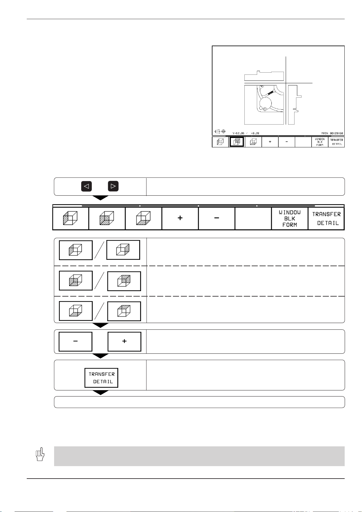
Magnifying details
You can magnify details in the TEST RUN mode of
operation in the following display modes:
• projection in three planes
• 3D view
provided that the graphic simulation is stopped. A
detail magnification is always effective in all three
display modes.
To select detail magnification:
Fig. 1.27: Magnifying a detail of a projection in three planes
or
Shift the soft-key row.
Select the left/right workpiece surface.
Select the front/back workpiece surface.
Select the top/bottom workpiece surface.
or
Shift sectional plane to reduce/magnify the blank form.
If desired
Select the isolated detail.
Restart the test run or program run.
If a graphic display is magnified, this is indicated with MAGN at the lower
right of the graphics window. If the detail is not magnified with TRANSFER
DETAIL, you can make a test run of the shifted sectional planes.
If the workpiece blank cannot be further enlarged or reduced, the TNC displays an error message in the graphics
window. The error message disappears when the workpiece blank is enlarged or reduced.
TNC 426/TNC 425/TNC 415 B/TNC 407 1-25
Page 44

1 Introduction
1.4 Graphics and Status Displays
Repeating graphic simulation
A part program can be graphically simulated as often as desired, either
with the complete workpiece blank or with a detail of it.
Function Soft key
Restore workpiece blank as it was last shown
Show the complete BLK FORM as it appeared
before a detail was magnified via TRANSFER
DETAIL
The WINDOW BLK FORM soft key will return the blank form to its original shape and size, even if a detail has
been isolated and not yet magnified with TRANSFER DETAIL.
Measuring the machining time
At the lower right of the graphics window the TNC
shows the calculated machining time in
hours : minutes : seconds
(maximum 99 : 59 : 59)
• Program run:
The clock counts and displays the time from
program start to program end. The clock stops
whenever machining is interrupted.
• Test run:
The clock shows the time which the TNC
calculates for the duration of tool movements.
To activate the stopwatch function:
or
Fig. 1.28: The calculated machining time is shown at the
lower right of the workpiece graphic
Press the shift keys until the soft-key row with the stopwatch
functions appears.
The soft keys available to the left of the stopwatch function depend on the selected display mode.
TNC 426/TNC 425/TNC 415 B/TNC 4071-26
Page 45

1 Introduction
1.4 Graphics and Status Displays
Stopwatch functions Soft key
Store displayed time
Show the sum of the stored time and
the displayed time
Clear displayed time
Status displays
During a program run mode of operation the status
display contains the current coordinates and the
following information:
• Type of position display (ACTL, NOML, ...)
• Number of the current tool T
• Tool axis
• Spindle speed S
• Feed rate F
• Active M functions
• “Control in operation” symbol: ❊
• “Axis is locked” symbol:
• Axis can be moved with the handwheel:
• Axes are moving in a tilted working plane:
• Axes are moving under a basic rotation:
Fig. 1.29: Status display in a program run mode of operation
Additional status displays
The additional status displays contain further information on the program
run.
To select additional status displays:
or
Set the STATUS soft key to ON.
Shift the soft-key row.
TNC 426/TNC 425/TNC 415 B/TNC 407 1-27
Page 46

1 Introduction
1.4 Graphics and Status Displays
Additional status display Soft key
General program information
Positions and coordinates
Tool information
Coordinate transformations
Tool measurement
General program information
Positions and coordinates
Name of main program
Active programs
Cycle definition
Dwell time counter
Machining time
Circle center CC (pole)
Type of position display
Coordinates of the axes
Tilt angle of the working plane
Display of a basic rotation
TNC 426/TNC 425/TNC 415 B/TNC 4071-28
Page 47

1 Introduction
1.4 Graphics and Status Displays
Tool information
Coordinate transformations
T: Tool name and number
RT: Name and number of a replacement tool
Tool axis
Tool length and radii
Oversizes (delta values)
Tool life, maximum tool life and maximum tool life
for TOOL CALL
Display of the programmed tool and the (next)
replacement tool
Main program name
Coordinates of the datum shift
Angle of basic rotation
Mirrored axis
Scaling factor(s)
Scaling datum
(conversational programming only)
Tool measurement (only available with conversational programming)
Number of the tool to be measured
Measured MIN and MAX values of the
single cutting edges and the result of
measuring the rotating tool
Display whether the tool radius or the tool length is
being measured
Cutting edge number with the corresponding
measured value. If the measured value is
followed by an asterisk, the allowable tolerance
defined in the tool table was exceeded.
TNC 426/TNC 425/TNC 415 B/TNC 407 1-29
Page 48

1 Introduction
1.5 File Management on the TNC 426
The functions described in this chapter are valid for the hard disk of the TNC and for the FE1 interface mode (see
page 10-4). If you wish to use these functions with a personal computer, you will need the HEIDENHAIN data transfer
software TNC.EXE.
Programs, texts and tables are written as files and
stored on the TNC's hard disk.
File identification:
PROG15 .I
File name File type
To open a new file you must enter a file name
consisting of up to eight characters (letters and
numbers).
You can manage any number of files on the TNC's
hard disk. Their total size, however, must not
exceed 170 M byte.
Files in the TNC Type
Programs
• in HEIDENHAIN plain language dialog .H
• in ISO format .I
Tables for
• Tools .T
• Pallets .P
• Datums .D
• Points (digitizing range for measuring
touch probe) .PNT
Texts as
• ASCII files .A
Fig. 1.35: Overview of file types in the TNC 426
To ensure that you can easily find your files, we
recommend that you organize your hard disk into
directories. Directories work like drawers in a filing
cabinet: They enable you to save your files in
groups according to some system. You could set up
your directories according to job number, for
example. The name of a directory can have up to
eight characters (letters and numbers).
If you divide a directory up into further directories,
these subordinate directories are called subdirec-
tories. The TNC shows subdirectories at the right of
and below their parent directories (see page 1-31).
Data security
We recommend to save newly written programs and files on a PC at
regular intervals. You can do this with the cost-free backup program
TNCBACK.EXE from HEIDENHAIN.
In addition, you need a floppy disk on which all machine-specific data,
such as PLC program, machine parameters, etc., are stored. Please
contact your machine manufacturer for more information on both the
backup program and the floppy disk.
TNC:\
AUFTR1
NCPROG
WZTAB
A35K941
ZYLM
TESTPROG
HUBER
KAR25T
Fig. 1.36: Directories on the hard disk of the TNC
Saving the entire hard disk (170 M bytes) may take several hours. In this
case, it is a good idea to save the data outside of work hours, e.g. during
the night.
TNC 426/TNC 425/TNC 415 B/TNC 4071-30
Page 49

1 Introduction
1.5 File Management on the TNC 426
Calling the file manager
Press the PGM MGT key to call the file manager. The screen will then look
something like this:
Drives
Directories
Active path or
file name
File information
Files stored in the
active directory
With the WINDOW soft key you can change the screen layout (see page
1-34). Whenever you press the PGM MGT key, the TNC shows the screen
layout that you last selected.
Drives:
RS232 interface
RS422 interface
TNC disk drive
The active drive is shown in a different color.
The drive symbol depends on the selected
interface mode (see page 10-4).
Directories:
File information:
• FILE NAME: Files stored in the active directory
• BYTES: Size of the file in bytes
• STATUS: The following letters may appear in the STATUS
column:
E: File is selected in the PROGRAMMING AND
S: File is selected in the TEST RUN operating
M: File is selected in a program run operating
P: File is protected against editing and erasure
IN: File contains inch dimensions
W: File was incompletely transferred to
• DATE: Date the file was last changed
• TIME: Time the file was last changed
EDITING operating mode
mode
mode
external storage and cannot be run
The TNC shows a subdirectory at the right of
and below its parent directory. The active
directory is depicted in a different color and
is indicated by an open file symbol.
TNC 426/TNC 425/TNC 415 B/TNC 407 1-31
Page 50

1 Introduction
1.5 File Management on the TNC 426
To select the drive:
➤ Press the leftward arrow key to move the highlight bar to the active
directory (left in the screen).
➤ Press the upward arrow key to move the highlight bar to the desired
drive.
➤ Once the highlight bar is on desired drive, confirm your selection with
ENT.
To create a new directory:
➤ Select the drive.
➤ Press the downward arrow key to move the highlight to the directory
under which you wish to open a new directory.
➤ Enter the name of the new directory (up to eight characters) and confirm
with ENT.
➤ Answer the TNC dialog question with the YES soft key if you wish to
create a new directory, or abort with NO.
To select the directory:
➤ Select the drive.
➤ Press the downward arrow key to move the highlight to the desired
directory. In the right screen window, the TNC automatically displays
the files stored in this directory.
or
➤ Press the leftward arrow key to move the highlight to the active directory
(left in the screen).
➤ Enter the path directly with the ASCII keyboard and confirm with ENT.
TNC 426/TNC 425/TNC 415 B/TNC 4071-32
Page 51

1 Introduction
1.5 File Management on the TNC 426
To select the file:
➤ Select the drive.
➤ Select the directory.
➤ Press the rightward arrow key to move the highlight to the file directory.
➤ Press the SELECT TYPE soft key to choose the file type (see page
1-36).
➤ Press the downward or upward arrow key to move the highlight to the
desired file.
➤ Once the highlight is on the desired file, confirm your selection with
ENT.
or
➤ Press the LAST FILES soft key. The TNC then displays the last ten files
you selected.
➤ Press the downward or upward arrow key to move the highlight to the
desired file.
➤ Once the highlight is on the desired file, confirm your selection with
ENT.
or
➤ Select the drive.
➤ Select the directory.
➤ Enter the file name directly with the ASCII keyboard.
Functions for selecting files Key / Soft key
Move the highlight bar upward
to the desired file
Move the highlight bar downward
to the desired file
Move pagewise up through
the file directory
Move pagewise down through
the file directory
Select the highlighted file
TNC 426/TNC 425/TNC 415 B/TNC 407 1-33
Page 52

1 Introduction
1.5 File Management on the TNC 426
With the WINDOW soft key you can change the screen layout to show the
contents of two different directories, one in each half of the screen. Use
this setting for copying files between directories and for importing or
exporting files. Press the WINDOW soft key again if you wish to return to
the other layout.
Active path
File information
File name
Active path
File information
File display:
Files stored in the
active directory
To select the directory:
➤ Press the leftward or rightward arrow key to switch to the window in
which you wish to select a new directory.
➤ Press the PATH soft key to switch to the path display. The TNC then
shows the drives (active drive is depicted in a different color) and the
active directory (also depicted in a different color).
➤ If you wish to change drives, press the upward arrow key to move the
highlight to the new drive.
➤ Once the highlight is on the desired drive, confirm your selection with
ENT. The TNC automatically returns to the file display. The window then
shows the files stored in the uppermost directory of the selected drive.
➤ If you wish to select a subdirectory, press the PATH soft key to return to
the path display.
➤ Press the downward arrow key to move the highlight to the desired
directory.
➤ Once the highlight is on the desired directory, confirm your selection
with ENT. The TNC then automatically switches back to the file window
containing the files stored in the selected directory.
File display:
Files stored in the
active directory
TNC 426/TNC 425/TNC 415 B/TNC 4071-34
Page 53

1 Introduction
1.5 File Management on the TNC 426
Functions for file management
The file management functions are selected by soft key after pressing
PMG MGT in the PROGRAMMING AND EDITING mode of operation. The
following functions are available:
Function Soft key
Select a file type
Copy a file (and convert)
Copy a directory
Erase a file or directory
Rename a file
Tag files
Read the tree structure of an external device
and show it on the TNC screen
Display the last ten files that were selected
Protect a file
Cancel file protection
Convert FK program
TNC 426/TNC 425/TNC 415 B/TNC 407 1-35
Page 54

1 Introduction
1.5 File Management on the TNC 426
Selecting file types
PGM
MGT
To copy individual files:
You must be in the PROGRAMMING AND EDITING mode of operation.
Call the file manager.
List the file types.
Show all files, or ...
show only one type, for example HEIDENHAIN conversational programs
(file type .H).
➤ Call the file manager with PGM MGT.
➤ Select the directory containing the file you wish to copy. Move the
highlight to the desired file.
➤ Press the COPY soft key.
➤ Type the new file name into the highlight in the screen headline.
➤ Press the ENT key or the EXECUTE soft key to copy the file into the
active directory. The original file is retained.
➤ Close the file manager with END.
• If you are copying tables, you can overwrite individual lines or columns in the target table with the REPLACE
FIELDS soft key. Prerequisites:
– The target table must exist.
– The file to be copied must only contain the columns (or lines) you want to replace.
• You can also copy an entire directory together with its subdirectories. Simply place the highlight on the directory
you wish to copy and press the COPY DIR soft key. Then proceed as described above in the section “To copy
individual files”.
TNC 426/TNC 425/TNC 415 B/TNC 4071-36
Page 55

1 Introduction
1.5 File Management on the TNC 426
To copy several files into another directory:
You must be in the PROGRAMMING AND EDITING mode of operation.
To select the functions for copying several files, press the TAG soft key:
Functions for tagging/copying files Soft key
Tag one file
Tag all files in the directory
Untag one file
Untag all files in the directory
Copy the tagged files
When overwriting several files, confirm
each file separately
➤ Call the file manager with PGM MGT.
➤ Arrange the screen layout with the WINDOW soft key to show file
names in both halves of the screen.
➤ In the right screen half, use the PATH soft key to select the directory into
which you wish to copy the files.
➤ Move the highlight to the left screen half.
➤ In the left screen half, use the PATH soft key to select the directory
containing the files that you want to copy.
➤ Move the highlight to the first file you want to copy.
➤ Shift the soft-key row.
➤ Select the file tagging function with the TAG soft key.
➤ Press the TAG FILE soft key. The TNC tags the highlighted file with an
arrow at its left and shows it in a different color.
➤ Move the highlight to the next file you want to copy. Tag the file with
TAG FILE. Tag all files you want to copy in this way.
➤ Press the COPY TAG soft key and confirm with ENT. Die TNC copies
the tagged files into the active directory in the right screen half. The
original files are retained.
➤ Close the file manager with END.
• If the target directory contains files with the same file names as the files to be copied, the TNC will ask you
whether you want to overwrite these files. Press the YES soft key to overwrite all files, or press the CONFIRM
soft key to confirm each file separately before overwriting it. If you want to overwrite a protected file, you can
suspend file protection during the copying process.
• When you are converting files with the TAG function, you can also use
example, you can convert all tagged files into ASCII text files.
• If you press the COPY TAG soft key with the screen layout showing drives/directories to the left and file names
to the right, the TNC asks you for a DESTINATION DIRECTORY. Enter the complete path name, including the
drive.
TNC 426/TNC 425/TNC 415 B/TNC 407 1-37
wildcards
(∗). By copying into ∗.A, for
Page 56

1 Introduction
1.5 File Management on the TNC 426
To erase a file:
➤ Call the file manager with PGM MGT.
➤ Select the directory containing the file you wish to erase. Move the
highlight to the desired file.
➤ Shift the soft-key row.
➤ Press the DELETE soft key.
➤ Press the YES soft key to delete the file, or abort the deleting function
with the NO soft key.
➤ Close the file manager with END.
You can also erase directories. Simply move the highlight to a directory instead of a file and proceed as described
above. Delete all files and subdirectories stored in this directory before erasing the actual directory.
To rename a file:
➤ Call the file manager with PGM MGT.
➤ Select the directory containing the file you wish to rename. Move the
highlight to the desired file.
➤ Shift the soft-key row.
➤ Press the RENAME soft key and enter the new file name.
➤ Press the ENT key or the EXECUTE soft key to rename the file. The
original file name is erased.
➤ Close the file manager with END.
To protect a file:
➤ Call the file manager with PGM MGT.
➤ Select the directory containing the file you wish to protect. Move the
highlight to the desired file.
➤ Shift the soft-key row.
➤ Press the MORE FUNCTIONS soft key.
➤ Press the PROTECT soft key. The file now has status P and cannot be
accidentally changed or erased.
➤ Close the file manager with END.
To cancel file protection:
➤ Call the file manager with PGM MGT.
➤ Select the directory containing the file whose protection you wish to
remove. Move the highlight to the desired file.
➤ Shift the soft-key row.
➤ Press the MORE FUNCTIONS soft key.
➤ Press the UNPROTECT soft key.
➤ Type the code number 86357 and confirm with ENT. File protection is
canceled, the file no longer has status P.
➤ Close the file manager with END.
TNC 426/TNC 425/TNC 415 B/TNC 4071-38
Page 57

1 Introduction
1.5 File Management on the TNC 426
To convert a file:
Two soft keys are provided for converting files:
Functions for converting files Soft key
FK program to HEIDENHAIN conversational format
HEIDENHAIN conversational format to OEM cycle
To copy a file type into ASCII format (.A), use the COPY function (see
page 1-36). Enter the file type .A for the destination file.
You can also convert an ASCII file into another format. To convert to ISO
format, for example, enter the file type .I for the destination file.
Example: Converting an FK program into HEIDENHAIN conversational format
➤ Call the file manager with PGM MGT.
➤ Select the directory containing the file you wish to convert. Move the
highlight to the desired file.
➤ Shift the soft-key row.
➤ Press the MORE FUNCTIONS soft key.
➤ Press the CONVERT FK –> H soft key.
➤ Type the new file name into the highlight in the screen headline and
confirm with ENT.
➤ Close the file manager with END.
TNC 426/TNC 425/TNC 415 B/TNC 407 1-39
Page 58

1 Introduction
1.6 File Management on the TNC 425, TNC 415 B and TNC 407
Programs, texts and tables are written as files and
stored in the TNC.
File identification:
PROG15PROG15
PROG15
PROG15PROG15
File name File type
To open a new file you must enter a file name
consisting of from one to 16 characters (letters
and numbers), depending on MP7222.
The file types are listed in the table at right.
File directory
The TNC can store up to 100 files at one time.
You can call up a directory of these programs by
pressing the PGM NAME key. To delete one or
more programs, press the CL PGM key.
The file directory contains the following
information:
• File name
• File type
• File size in bytes (=characters)
• File status
Further information is shown at the top of the
screen:
• Selected file storage
- TNC memory
- External storage over RS-232 interface
- External storage over RS-422
• Interface mode (e.g., FE1, EXT1 for external
storage)
• File type (e.g., ❊ .H if only HEIDENHAIN
dialog programs are shown)
Files in the TNC Type
Programs
.I.I
.I
.I.I
• in HEIDENHAIN plain language dialog .H
• in ISO format .I
Tables for
• Tools .T
• Pallets .P
• Datums .D
• Points (digitizing range for measuring
touch probe) .PNT
Texts as
• ASCII files .A
Fig. 1.39: TNC file types
Task Mode of Call file directory
operation with
Create new files
Edit files
Erase files
Test files
Execute files
Fig. 1.40: File management functions
PGM
NAME
PGM
NAME
CL
PGM
PGM
NAME
PGM
NAME
Example:
RS 422/EXT1: ❊ .T is displayed. This means that only
those files are shown that have the extension .T
and are located in an external storage device (e.g.
a PC) that is connected to the TNC over the
RS-422 interface (see also Chapter 10).
A soft key calls the file directory of an external
data storage medium. The screen is then divided
into two columns.
Select the file directory:
Show the file directory in one or two columns. The selected layout is
shown in the soft key.
Fig. 1.41: Files are sorted alphabetically and according to
type
TNC 426/TNC 425/TNC 415 B/TNC 4071-40
Page 59

1 Introduction
1.6 File Management on the TNC 425, TNC 415 B and TNC 407
File status
The letters in the STATUS column give the following information about the
files:
E: File is selected in the PROGRAMMING AND EDITING
operating mode
S: File is selected in the TEST RUN operating mode
M: File is selected in a program run operating mode
P: File is protected against editing and erasure
IN: File contains inch dimensions
W: File has been transferred to external storage and cannot be run
Selecting a file
You must be in the PROGRAMMING AND EDITING mode of operation.
➤ Call the file manager with PGM NAME.
➤ Display the file type soft-key row with the SELECT TYPE soft key. Then
press the soft key for the desired file type, for example SHOW .I for ISO
programs.
➤ Use the arrow keys to move the highlight bar to the desired file.
➤ Confirm your selection with the SELECT soft key or with ENT.
➤ Close the file manager with END.
Functions for selecting files Key/
Soft key
Move the highlight bar upward
to the desired file
Move the highlight bar downward
to the desired file
Move pagewise up through
the file directory
Move pagewise down through
the file directory
Select the highlighted file
TNC 426/TNC 425/TNC 415 B/TNC 407 1-41
Page 60

1 Introduction
1.6 File Management on the TNC 425, TNC 415 B and TNC 407
To copy a file:
➤ Call the file manager with PGM NAME.
➤ Move the highlight to the file you wish to copy.
➤ Press the COPY soft key.
➤ Type the new file name into the highlight in the screen headline.
➤ Press ENT to copy the file. The original file is retained.
➤ Close the file manager with END.
To erase a file:
➤ Press CL PGM.
➤ Move the highlight to the file you wish to delete.
➤ Press the DELETE soft key to erase the highlighted file.
➤ Close the file manager with END.
To rename a file:
➤ Call the file manager with PGM NAME.
➤ Move the highlight to the file you wish to rename.
➤ Shift the soft-key row.
➤ Press the RENAME soft key and type the new file name into the
highlight in the screen headline.
➤ Press ENT to rename the file. The original file name is erased.
➤ Close the file manager with END.
To protect a file:
➤ Call the file manager with PGM NAME.
➤ Move the highlight to the file you wish to protect.
➤ Shift the soft-key row.
➤ Press the PROTECT soft key. The file now has status P and cannot be
accidentally changed or erased.
➤ Close the file manager with END.
To cancel file protection:
➤ Call the file manager with PGM MGT.
➤ Move the highlight to the file whose protection you wish to remove.
➤ Shift the soft-key row.
➤ Press the UNPROTECT soft key.
➤ Type the code number 86357 and confirm with ENT. File protection is
canceled, the file no longer has status P.
➤ Close the file manager with END.
TNC 426/TNC 425/TNC 415 B/TNC 4071-42
Page 61

1 Introduction
1.6 File Management on the TNC 425, TNC 415 B and TNC 407
To convert a file:
Text files (type .A) can be converted to any other type. Other types of files
can only be converted into ASCII text files. They can then be edited with
the alphanumeric keyboard.
Part programs that were created with FK free contour programming
can also be converted to HEIDENHAIN conversational programs.
➤ Call the file manager with PGM NAME.
➤ Move the highlight to the file you wish to convert.
➤ Shift the soft-key row.
➤ Press the CONVERT soft key
➤ Press the CONVERT FK –> H soft key.
➤ Type the new file name into the highlight in the screen headline and
confirm with ENT.
➤ Close the file manager with END.
File management for files on external data media
You can erase and protect files stored on the FE 401B floppy disk unit
from HEIDENHAIN. You can also format a floppy disk from the TNC. To do
this you must first select the PROGRAMMING END EDITING mode of
operation.
To erase a file on the FE 401B:
➤ Press the EXT key. The TNC displays the files stored in the TNC
memory in the left screen half, and the files stored on the FE 401 in the
right screen half.
➤ Move the highlight to the right screen half.
➤ Press the WINDOW soft key to select one-window mode.
➤ Move the highlight to the file you wish to delete.
➤ Press the DELETE soft key.
➤ Close the file manager with END.
To protect a file on the FE 401B:
➤ Press the EXT key. The TNC displays the files stored in the TNC
memory in the left screen half, and the files stored on the FE 401 in the
right screen half.
➤ Move the highlight to the right screen half.
➤ Press the WINDOW soft key to select one-window mode.
➤ Move the highlight to the file you wish to protect.
➤ Shift the soft-key row.
➤ Press the PROTECT soft key. The file now has status P and cannot be
accidentally changed or erased.
➤ Close the file manager with END.
To cancel file protection on the FE 401B:
➤ Press the EXT key. The TNC displays the files stored in the TNC
memory in the left screen half, and the files stored on the FE 401 in the
right screen half.
➤ Move the highlight to the right screen half.
➤ Press the WINDOW soft key to select one-window mode.
➤ Move the highlight to the file whose protection you wish to remove.
➤ Shift the soft-key row.
➤ Press the UNPROTECT soft key.
➤ Type the code number 86357 and confirm with ENT. File protection is
canceled, the file no longer has status P.
➤ Close the file manager with END.
TNC 426/TNC 425/TNC 415 B/TNC 407 1-43
Page 62

1 Introduction
1.6 File Management on the TNC 425, TNC 415 B and TNC 407
To format a floppy disk in the FE 401B:
➤ Press the EXT key. The TNC displays the files stored in the TNC
memory in the left screen half, and the files stored on the FE 401 in the
right screen half.
➤ Move the highlight to the right screen half.
➤ Press the WINDOW soft key to select one-window mode.
➤ Shift the soft-key row.
➤ Press the FMT soft key.
➤ Enter a name for the diskette and start formatting with ENT.
➤ Close the file manager with END.
To convert and transfer files:
➤ Press the EXT key.
➤ Move the highlight in the left screen half to the file you wish to convert
and transfer.
➤ Shift the soft-key row.
➤ Press the CONVERT soft key
➤ Press the CONVERT –> .A soft key, for example, to convert the file into
an ASCII text file and store it on the FE 401.
➤ Type the new file name into the highlight in the screen headline and
confirm with ENT.
➤ Close the file manager with END.
TNC 426/TNC 425/TNC 415 B/TNC 4071-44
Page 63

2 Manual Operation and Setup
2.1 Moving the Machine Axes
Traversing with the machine axis direction buttons
Traversing with the machine axis direction buttons can vary depending on the individual machine tool. Your
machine manual provides more information on this function.
MANUAL OPERATION
e.g.
X
You can move more than one axis at once in this way.
For continuous movement
MANUAL OPERATION
e.g.
Y
You can move more than one axis at once in this way.
I
together
The axis moves as long as the corresponding axis direction button is
held down.
Press and hold the machine axis direction button, then press the
machine START button.
The axis continues to move after you release the keys.
To stop the axis, press the machine STOP button.
TNC 426/TNC 425/TNC 415 B/TNC 4072-2
Page 64

2 Manual Operation and Setup
2.1 Moving the Machine Axes
Traversing with an electronic handwheel
ELECTRONIC HANDWHEEL
INTERPOLATION FACTOR: X = 3
e.g.
3
e.g.
Now move the selected axis with the electronic handwheel. If you are
using the portable handwheel, first press the enabling switch (on side of
handwheel).
Interpolation factor Traverse in mm
0 20.000
1 10.000
2 5.000
3 2.500
4 1.250
5 0.625
6 0.312
7 0.156
8 0.078
9 0.039
10 0.019
ENT
X
per revolution
Enter the interpolation factor (see table).
Select the axis that you wish to move. For portable handwheels make
the selection at the handwheel; for integral handwheels, at the TNC
keyboard.
Fig. 2.1: Interpolation factors for handwheel speed
The smallest programmable interpolation factor depends on the specific machine tool. Your machine manual
provides more detailed information on this subject.
Using the HR 330 electronic handwheel
The HR 330 portable handwheel has an enabling switch that is located on
the side opposite to the star grip and the EMERGENCY STOP switch.
You can only move the machine axes when the enabling switch is
depressed.
• As long as the handwheel is attached to the machine tool, the enabling switch is automatically depressed.
• Attach the electronic handwheel to a steel surface with the mounting magnets such that it cannot be operated
unintentionally.
• Be sure not to press the axis direction keys unintentionally while the enabling switch is depressed when you
remove the handwheel from its position.
Fig. 2.2: HR 330 electronic handwheel
TNC 426/TNC 425/TNC 415 B/TNC 407 2-3
Page 65
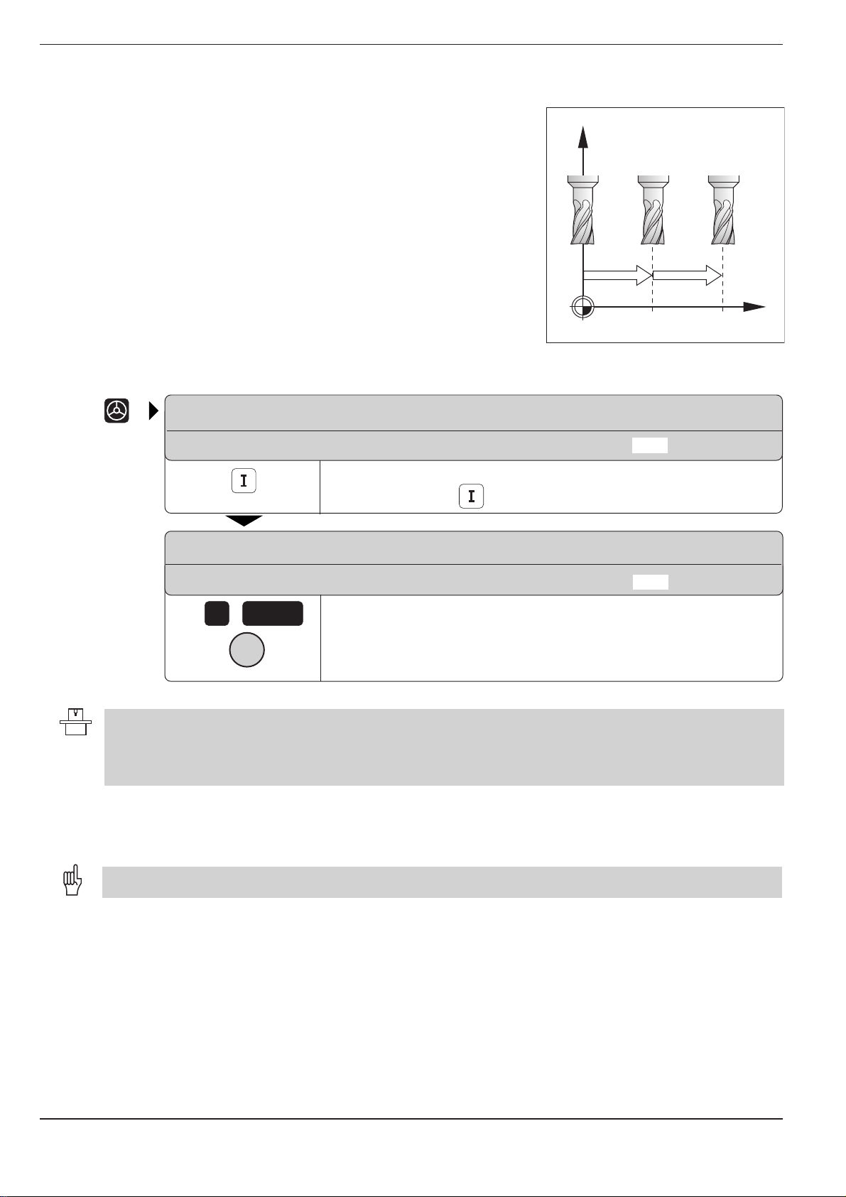
2 Manual Operation and Setup
Z
X
8 8
816
2.1 Moving the Machine Axes
Incremental jog positioning
With incremental jog positioning, a machine axis moves by a preset
distance each time you press the corresponding machine axis direction
button.
Fig. 2.3: Incremental jog positioning in the
ELECTRONIC HANDWHEEL
INTERPOLATION FACTOR: X = 4
Select incremental jog positioning with a key defined by your machine
manufacturer (here, ).
ELECTRONIC HANDWHEEL
JOG INCREMENT: 4 8
e.g.
8
e.g.
• Incremental jog positioning can vary depending on the individual machine tool. Your machine manual provides
more information on this function.
• The machine tool builder determines whether the interpolation factor for each axis is set at the keyboard or
with a step switch.
ENT
X
Enter the jog increment (here, 8 mm).
Press the machine axis direction button as often as desired.
X axis
Positioning with manual data input (MDI)
Machine axis movement can also be programmed in the $MDI file (see page 5-45).
Since the programmed movements are stored in memory, you can recall
them and run them afterward as often as desired.
TNC 426/TNC 425/TNC 415 B/TNC 4072-4
Page 66
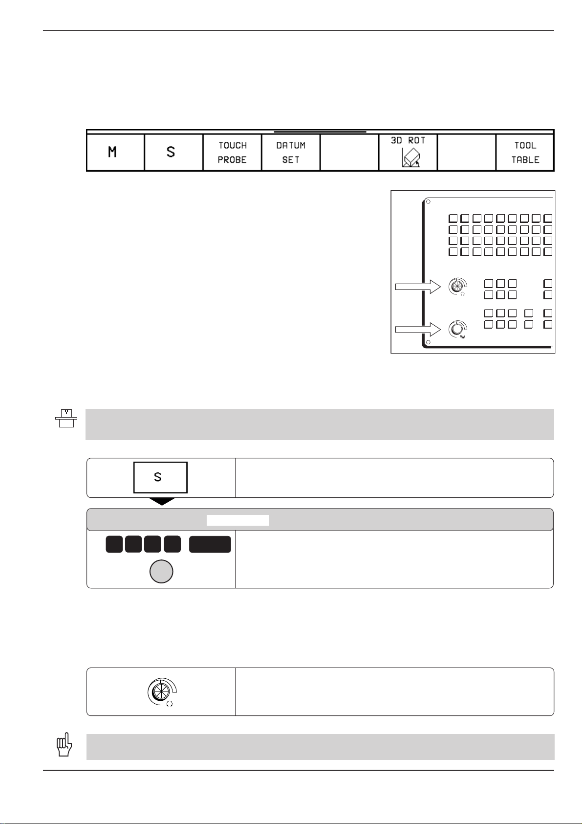
2 Manual Operation and Setup
S%
F%
0
100
15050
S %
0
100
15050
F %
2.2 Spindle Speed S, Feed Rate F and Miscellaneous Functions M
These are the soft keys in the MANUAL OPERATION and ELECTRONIC
HANDWHEEL modes:
With these functions and with the override knobs on the TNC keyboard
you can change and enter:
• spindle speed S
• feed rate F (only via override knob)
• miscellaneous functions M
These functions are entered directly in a part program in the
PROGRAMMING AND EDITING mode.
To enter the spindle speed S:
The machine tool builder determines which spindle speeds are allowed on your TNC. Your machine manual
provides more information on the available spindle speeds.
SPINDLE SPEED S =
e.g.
0
0
1
0
I
The spindle speed S with the entered rpm is started with a miscellaneous
function M.
ENT
Fig. 2.4: Knobs for spindle speed and feed
rate overrides
Select S for spindle speed.
Enter the desired spindle speed (for example, 1000 rpm).
Press the machine START button to confirm the entered spindle
speed.
To change the spindle speed S:
100
15050
S %
0
The knob for spindle speed override is effective only on machines with a stepless spindle drive.
TNC 426/TNC 425/TNC 415 B/TNC 407 2-5
Turn the knob for spindle speed override:
You can vary the spindle speed from 0% to 150% of the last entered
value.
Page 67

2 Manual Operation and Setup
2.2 Spindle Speed S, Feed Rate F and Miscellaneous Functions M
To change the feed rate F:
In the MANUAL OPERATION mode the feed rate is set by a machine
parameter.
100
15050
F %
0
Turn the knob for feed rate override.
You can vary the feed rate from 0% to 150% of the set value.
To enter a miscellaneous function M:
The machine tool builder determines which miscellaneous functions are available on your TNC and what effects they
have.
Select M for miscellaneous function.
MISCELLANEOUS FUNCTION M =
e.g.
6
ENT
Enter the miscellaneous function (for example, M6).
Press the START button to activate the miscellaneous function.
I
See Chapter 11 for a list of the miscellaneous functions.
TNC 426/TNC 425/TNC 415 B/TNC 4072-6
Page 68

2 Manual Operation and Setup
2.3 Setting the Datum Without a 3D Touch Probe
You fix a datum by setting the TNC position display to the coordinates of a
known point on the workpiece. The fastest, easiest and most accurate
way of setting the datum is by using a 3D touch probe from HEIDENHAIN
(see page 2-14).
To prepare the TNC:
Clamp and align the workpiece.
Insert the zero tool with known radius into the spindle.
or
Ensure that the TNC is showing the actual values (see page 10-8).
Setting the datum in the tool axis
Fragile workpiece?
If the workpiece surface must not be scratched,
you can lay a metal shim of known thickness
on it. Then enter a tool axis datum value that is
larger than desired datum by the value d.
Select the MANUAL OPERATION or ELECTRONIC HANDWHEEL
mode.
d
Z
Z
d
X
Fig. 2.5: Workpiece setting in the tool axis;
right
, with protective shim
X
Move the tool until it touches the workpiece surface.
e.g.
Z
ELECTRONIC HANDWHEEL
only:
e.g.
0
e.g.
5
0
TNC 426/TNC 425/TNC 415 B/TNC 407 2-7
ENT
ENT
Select the tool axis.
Select datum setting.
Zero tool. Set the display to Z = 0 or enter the thickness
L
Preset tool: Set the display to the length
(here Z = 50 mm or enter the sum Z = L + d
of the tool,
d
of the shim.
Page 69
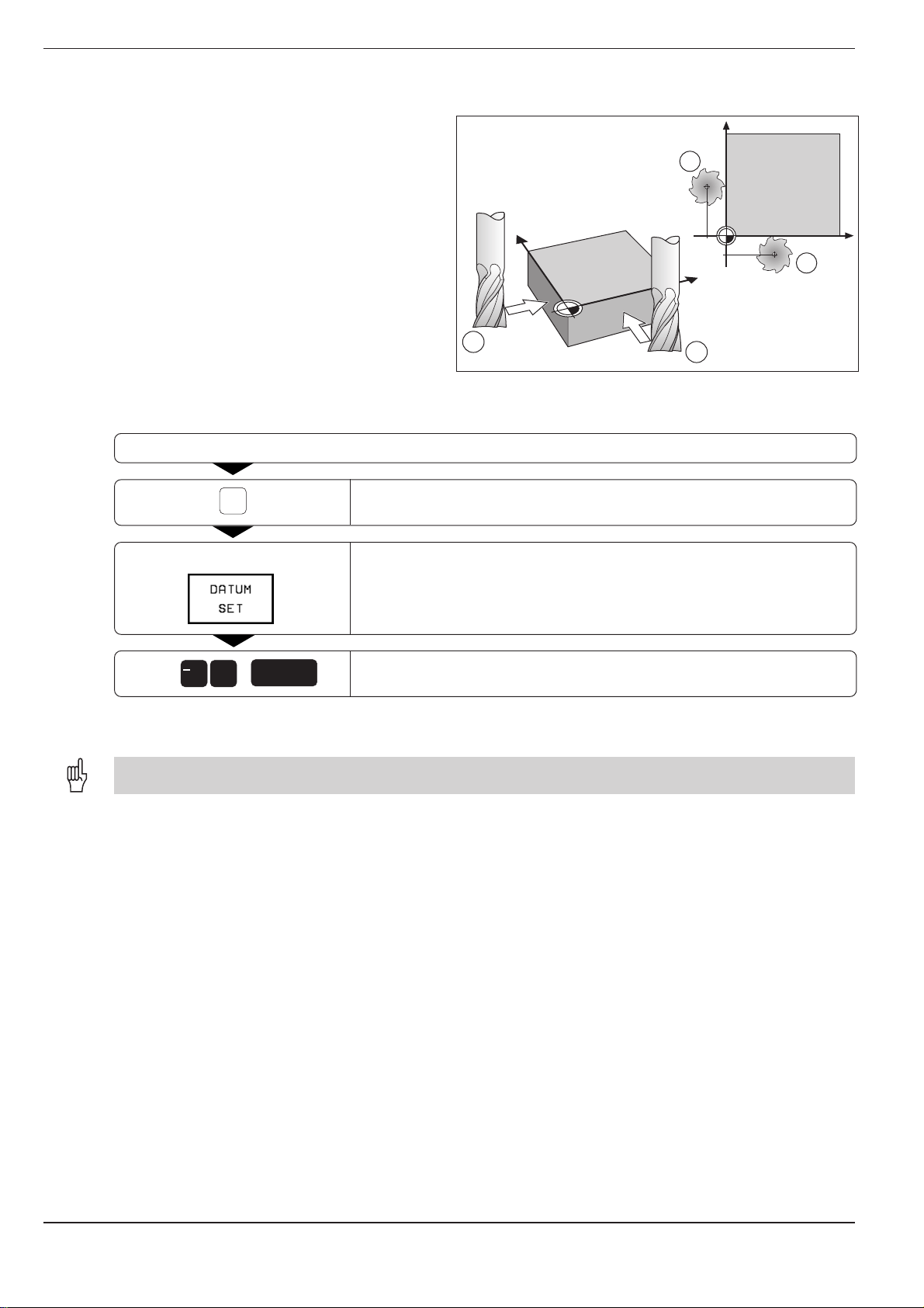
2 Manual Operation and Setup
2.3 Setting the Datum Without a 3D Touch Probe
To set the datum in the working plane:
Move the zero tool until it touches the side of the workpiece.
e.g.
X
ELECTRONIC HANDWHEEL
only:
1
Fig. 2.6: Setting the datum in the working plane; plan view
Select the axis.
Select datum setting.
Y
right)
1
–R
X
2
Y
–R
2
(upper
X
/
e.g.
Repeat the process for all axes in the working plane.
The exact dialog for datum setting depends on machine parameters MP 7295 and MP 7296 (see page 11-11).
+
5
ENT
Enter the position of the tool center (here, X = 5 mm) including the
sign.
TNC 426/TNC 425/TNC 415 B/TNC 4072-8
Page 70

2 Manual Operation and Setup
2.4 3D Touch Probes
3D Touch probe applications
Your TNC supports a HEIDENHAIN 3D touch probe.
Typical applications for touch probes:
• Compensating misaligned workpieces (basic
rotation)
• Datum setting
• Measuring:
- lengths and workpiece positions
- angles
- radii
- circle centers
• Measurements during program run
• Digitizing 3D surfaces
Fig. 2.7: 3D touch probe model TS 120
• The TNC must be specially prepared by the machine manufacturerer for the use of a 3D touch probe.
• If you wish to make measurements during program run, ensure that the tool data (length, radius, axis) are taken
either from the calibrated data or from the last TOOL CALL block (selection through MP 7411, see page 11-13).
After you press the machine START button, the touch probe begins
executing the selected probing function. The machine tool builder sets the
feed rate F at which the probe approaches the workpiece (MP6120).
When the touch probe contacts the workpiece, it
• transmits a signal to the TNC (the coordinates of the probed position
are stored),
• stops moving, and
• returns to its starting position at rapid traverse.
If the stylus is not deflected within the distance defined
in MP 6130, the TNC displays an error message.
To select the touch probe functions:
F
F
max
Fig. 2.8: Feed rates during probing
F
MANUAL OPERATION
or
ELECTRONIC HANDWHEEL
Select the touch probe functions.
TNC 426/TNC 425/TNC 415 B/TNC 407 2-9
Page 71

2 Manual Operation and Setup
2.4 3D Touch Probes
Calibrating the 3D touch probe
The touch probe must be calibrated in the following cases:
• for commissioning
• after stylus breakage
• when the stylus is changed
• when the probing feed rate is changed
• in the case of irregularities, such as those resulting from warming
of the machine.
During calibration, the TNC finds the "effective" length of the stylus and
the "effective" radius of the ball tip. To calibrate the touch probe, clamp a
ring gauge of known height and known inside radius to the machine table.
Z
Y
5
To calibrate the effective length:
Set the datum in the tool axis such that for the machine tool table, Z=0.
Select the calibration function for the touch probe length.
MANUAL OPERATION
Z+ Z–
TOOL AXIS = Z
e.g.
Z
e.g.
5
Move the touch probe to a position just above the ring gauge.
If necessary, enter the tool axis.
Move the highlight to DATUM.
Enter the height of the ring gauge (here, 5 mm).
X
Fig. 2.9: Calibrating the touch probe length
or
If necessary, change the displayed traverse direction.
The touch probe contacts the upper surface of the ring gauge.
I
TNC 426/TNC 425/TNC 415 B/TNC 4072-10
Page 72

2 Manual Operation and Setup
2.4 3D Touch Probes
To calibrate the effective radius
Position the ball tip in the bore hole of the ring gauge.
Compensating center misalignment
After the touch probe is inserted it normally needs to be exactly aligned
with the spindle axis. The misalignment is measured with this calibration
function and automatically compensated electronically.
For this operation the 3D touch probe is rotated by 180°. The rotation is
initiated by a miscellaneous function that is set by the machine tool builder
in the machine parameter MP 6160.
Z
Y
10
The center misalignment is measured after the effective ball tip radius is
calibrated.
Select the calibrating function for the ball-tip radius and the touch
probe center misalignment.
MANUAL OPERATION
X + X – Y + Y –
TOOL AXIS = Z
RADIUS RING GAUGE = 0
4x
I
The touch probe contacts a position on the bore in each axis direction;
the effective ball-tip radius is stored.
X
Fig. 2.10: Calibrating the touch probe radius
and determining center
misalignment
Determine the ball-tip center misalignment (or terminate the
calibration function with END): rotate the touch probe by 180°.
4x
I
TNC 426/TNC 425/TNC 415 B/TNC 407 2-11
The touch probe contacts one position on the bore hole for each axis
direction; the touch probe center misalignment is stored.
Page 73

2 Manual Operation and Setup
2.4 3D Touch Probes
Displaying calibration values
The effective length and radius, and the center
misalignment of the 3D touch probe are stored in
the TNC for use when the touch probe is needed
again. You can display the values on the screen
with the soft keys CAL L and CAL R.
E 4
Compensating workpiece misalignment
The TNC electronically compensates workpiece
misalignment by computing a "basic rotation".
You set the rotation angle to the desired angle with
respect to the reference axis in the working plane
(see page 1-13).
Fig. 2.11: Menu for touch probe radius and center
Fig. 2.12: Basic rotation of a workpiece; probing procedure for
compensation
position, the angle H is being compensated.
Press the PROBING ROT soft key.
misalignment
H
(right)
. The broken line is the nominal
2
1
A B
ROTATION ANGLE =
e.g.
0
Move the ball tip
(A)
to a starting position near the first touch point
.
.
.
ENT
Enter the nominal value of the rotation angle.
(1)
.
TNC 426/TNC 425/TNC 415 B/TNC 4072-12
Page 74

2 Manual Operation and Setup
2.4 3D Touch Probes
.
.
.
X + X – Y + Y –
or
Select the probe direction.
Probe the workpiece.
I
(B)
Move the ball tip
to a starting position near the second touch point
Probe the workpiece.
I
A basic rotation is kept in non-volatile storage and is effective for all
subsequent program runs and graphic simulation.
Displaying basic rotation
The angle of the basic rotation appears after
ROTATION ANGLE whenever PROBING ROT is
selected. It is also shown in the additional status
display (see page 1-27) under ROTATION.
In the status display, a symbol is shown for a basic
rotation whenever the TNC is moving the axes
according to a basic rotation.
(2)
.
Fig. 2.13: Displaying the angle of an active basic rotation.
To cancel a basic rotation:
Select the probing function with the soft key PROBING ROT.
ROTATION ANGLE =
0
TNC 426/TNC 425/TNC 415 B/TNC 407 2-13
ENT
END
Set the rotation angle to 0.
Terminate the probing function.
Page 75

2 Manual Operation and Setup
2.5 Setting the Datum with a 3D Touch Probe
The following functions are available for setting the datum on an aligned
workpiece:
• Datum setting in any axis with PROBING POS
• Defining a corner as datum with PROBING P
• Setting the datum at a circle center with PROBING CC
To set the datum in an axis:
Y
Z
Select the probing function with the soft key PROBING POS.
Move the touch probe to a position near the touch point.
X + X – Y + Y – Z + Z –
or
Select the probe axis and direction in which you wish to set the datum,
such as Z in direction Z–.
Probe the workpiece.
I
1
Fig. 2.14: Probing for the datum in the Z axis
X
e.g.
0
ENT
Enter the nominal coordinate of the datum.
TNC 426/TNC 425/TNC 415 B/TNC 4072-14
Page 76

2 Manual Operation and Setup
2.5 Setting the Datum with a 3D Touch Probe
Corner as datum
Y
Y=?
X=?
Fig. 2.15: Probing procedure for finding coordinates of corner P
Select the probing function with the soft key PROBING P.
To use the points that were already probed for a basic rotation:
TOUCH POINTS OF BASIC ROTATION?
ENT
Transfer the touch point coordinates to memory.
Y
4
3
1
P
P
X
2
X
Move the touch probe to a starting position near the first touch point of the side that was not probed for basic
rotation.
X + X – Y + Y –
or
Select the probe direction.
Probe the workpiece.
I
Move the touch probe to a position near the second touch point on the same side.
Probe the workpiece.
I
DATUM
e.g.
0
ENT
.
.
.
Enter the first coordinate of the datum point (for example, in the X
axis).
TNC 426/TNC 425/TNC 415 B/TNC 407 2-15
Page 77

2 Manual Operation and Setup
2.5 Setting the Datum with a 3D Touch Probe
.
.
.
DATUM
Select the second coordinate.
ENT
END
If you do
e.g.
0
not
wish to use the points that were already probed for a basic rotation:
TOUCH POINTS OF BASIC ROTATION?
NO
ENT
Probe both workpiece sides twice each.
Enter the coordinates of the datum.
Enter the second coordinate of the datum (for example, in the Y axis).
Terminate the probing function.
Ignore the previous touch point coordinates.
TNC 426/TNC 425/TNC 415 B/TNC 4072-16
Page 78

2 Manual Operation and Setup
Y
X
X–
X+
Y+
Y–
2.5 Setting the Datum with a 3D Touch Probe
Circle center as datum
With this function you can set the datum at the center of bore holes,
circular pockets, cylinders, journals, circular islands, etc.
Inside circle
The TNC automatically probes the inside wall in all four coordinate axis
directions.
For incomplete circles (circular arcs) you can choose the appropriate
probing directions.
Select the probing function with the soft key PROBING CC.
Move the touch probe to a position approximately in the center of the circle.
X + X – Y + Y –
The probe touches four points on the inside of the circle.
4 x
4 x
END
I
Rotate the touch probe by 180° if you are probing to find the stylus
center (only available on machines with spindle orientation,
depending on MP6160). Then probe another four points on the inside
of the circle.
I
Terminate the probing function for finding the stylus center.
.
.
.
Fig. 2.16: Probing the inside of a cylindrical
surface to find the center
TNC 426/TNC 425/TNC 415 B/TNC 407 2-17
Page 79

2 Manual Operation and Setup
Y
X
X–
X+
Y+
Y–
3
1
2
4
2.5 Setting the Datum with a 3D Touch Probe
.
.
.
DATUM
e.g.
DATUM
e.g.
1
Outside circle
0
ENT
0
END
ENT
Enter the first coordinate of the datum (for example, in the X axis).
Select the second coordinate.
Enter the second coordinate of the datum (for example, in the Y
axis).
Terminate the probing function.
Move the touch probe to the starting position near the first touch point
X + X – Y + Y –
or
Select the probing direction.
Probe the workpiece.
I
Repeat the probing process for points 2, 3 and 4 (see illustration).
Enter the coordinates of the datum.
After the probing procedure is completed, the TNC displays the
coordinates of the circle center and the circle radius PR.
Fig. 2.17: Probing the outside of a cylindrical
(1)
outside of the circle.
TNC 426/TNC 425/TNC 415 B/TNC 4072-18
surface to find the center
Page 80

2 Manual Operation and Setup
2.5 Setting the Datum with a 3D Touch Probe
Setting datum points over holes
A second soft-key row provides soft keys for using
holes to set datums.
The touch probe is used in the same way as in the
"circle center as datum" function (see page 2-17).
First pre-position it in the approximate center of a
hole, then press the machine START button to
automatically probe four points in the hole.
Move the touch probe to the next hole and have
the TNC repeat the probing procedure until all the
holes have been probed to set datums.
Function Soft key
Basic rotation from 2 holes:
The TNC measures the angle between the line connecting the centers
of two holes and a nominal angular position (angle reference axis).
Datum from 4 holes:
The TNC calculates the intersection of the line connecting the first two probed
holes with the line connecting the last two probed holes. If a basic rotation was
already made from the first two holes, these holes do not need to be probed again.
Circle center from 3 holes:
The TNC calculates a circle that intersects the centers of all three holes,
and finds the center.
Fig. 2.18: Second soft-key row for TOUCH PROBE
TNC 426/TNC 425/TNC 415 B/TNC 407 2-19
Page 81

2 Manual Operation and Setup
2.6 Measuring with a 3D Touch Probe
With a 3D touch probe you can determine
• position coordinates, and from them,
• dimensions and angles on the workpiece.
To find the coordinates of a position on an aligned workpiece:
Select the probing function with the soft key PROBING POS.
Move the touch probe to a position near the touch point.
X + X – Y + Y – Z + Z –
or
Select the probe direction and axis of the coordinate.
Probe the workpiece.
I
The TNC shows the coordinates of the touch point as DATUM.
Finding the coordinates of a corner in the working plane
Find the coordinates of the corner point as described under “Corner as
datum.” The TNC displays the coordinates of the probed corner as
DATUM.
TNC 426/TNC 425/TNC 415 B/TNC 4072-20
Page 82

2 Manual Operation and Setup
2.6 Measuring with a 3D Touch Probe
Measuring workpiece dimensions
Select the probing function with the soft key PROBING POS.
Move the touch probe to a position near the first touch point
X + X – Y + Y – Z + Z –
or
Select the probing direction with the cursor keys.
(1)
Y
2
l
1
Z
X
Fig. 2.19: Measuring lengths with the 3D
.
touch probe
Probe the workpiece.
I
If you will need the current datum later, write down the value that appears in the DATUM display.
DATUM
0
Move the touch probe to a position near the second touch point
ENT
END
.
.
.
Set the DATUM to 0.
Terminate the dialog.
Select the probe function again with the soft key PROBING POS.
(2)
.
TNC 426/TNC 425/TNC 415 B/TNC 407 2-21
Page 83

2 Manual Operation and Setup
2.6 Measuring with a 3D Touch Probe
.
.
.
X + X – Y + Y – Z + Z –
or
I
The value displayed as DATUM is the distance between the two points.
To return to the datum that was active before the length measurement:
Select the probe direction with the cursor keys – same axis as for
Probe the workpiece.
Select the probing function with the soft key PROBING POS.
1
.
Probe the first touch point again.
Set the DATUM to the value that you wrote down previously.
Measuring angles
You can also use the touch probe to measure angles in the working plane.
You can measure
• the angle between the angle reference axis and a workpiece side, or
• the angle between two sides.
The measured angle is displayed as a value of maximum 90°.
To find the angle between the angle reference axis and a side of the workpiece:
END
Terminate the dialog.
Select the probing function with the soft key PROBING ROT.
ROTATION ANGLE
If you will need the current basic rotation later, write down the value that appears under ROTATION ANGLE.
Make a basic rotation with the side of the workpiece (see section “Compensating workpiece misalignment”).
.
.
.
TNC 426/TNC 425/TNC 415 B/TNC 4072-22
Page 84

2 Manual Operation and Setup
2.6 Measuring with a 3D Touch Probe
.
.
.
Cancel the basic rotation.
To restore the previous basic rotation:
Set the ROTATION ANGLE to the value you wrote down previously.
To measure the angle between two sides of a workpiece:
Display the angle between the angle reference axis and the side of
the workpiece as the ROTATION ANGLE.
PA
Fig. 2.20: Measuring the angle between two
Select the probing function with the PROBING ROT soft key.
ROTATION ANGLE
If you will need the current basic rotation later, write down the value that appears under ROTATION ANGLE.
Make a basic rotation for the first side (see "Compensating workpiece misalignment").
Probe the second side as for a basic rotation, but do
The angle PA between the two sides appears under ROTATION
ANGLE.
not
set the ROTATION ANGLE to zero!
sides of a workpiece
Cancel the basic rotation.
To restore the previous basic rotation:
Set the ROTATION ANGLE to the value you wrote down previously.
TNC 426/TNC 425/TNC 415 B/TNC 407 2-23
Page 85

2 Manual Operation and Setup
2.7 Tilting the Working Plane
The functions for tilting the working plane are interfaced to the TNC and the machine tool by the machine tool builder.
On the TNC 426, the machine tool builder also determines whether the entered angles are interpreted as coordinates
of the tilt axes or as solid angles. Your machine manual provides more detailed information on this subject.
The working plane is always tilted around the active datum.
The TNC supports machine tools with swivel heads (the tool is tilted)
and/or tilting tables (the workpiece is tilted).
The program is written as usual in a main plane, such as the X/Y plane, but
is executed in a plane that is tilted relative to the main plane.
Typical applications:
• Oblique holes
• Contours in an oblique plane
There are two ways to tilt the working plane:
• 3D ROT soft key in the MANUAL OPERATION and ELECTRONIC
HANDWHEEL operation modes
• Cycle G80 WORKING PLANE in the part program (see page 8-55)
The tilting functions are coordinate transformations. The transformed tool
axis (i.e., as calculated by the TNC) always remains parallel to the actual
tool axis (the axis being positioned). The working plane is always
perpendicular to the direction of the tool axis.
407
When tilting the working plane, the TNC differentiates between two
machine types:
• Machines with tilting tables
• Machines with swivel heads
Machines with tilting tables:
• You must bring the workpiece into the desired position for machining
by positioning the tilting table, for example with a G00 block.
• The position of the transformed tool axis does not change in relation
to the machine-based coordinate system. Thus if you rotate the table—
and therefore the workpiece—by 90° for example, the coordinate
system does not rotate. If you press the Z+ axis direction button in
the MANUAL OPERATION mode, the tool moves in Z+ direction.
• In calculating the transformed coordinate system the TNC considers
only the mechanically influenced offsets of the particular tilting table
(the so-called “translational” components).
TNC 426/TNC 425/TNC 415 B/TNC 4072-24
Page 86

2 Manual Operation and Setup
2.7 Tilting the Working Plane
Machines with swivel heads:
• You must bring the tool into the desired position for machining by
positioning the swivel head, for example with a G00 block.
• The position of the transformed tool axis (like the position of the tool)
changes in relation to the machine-based coordinate system. Thus if
you rotate the swivel head—and therefore the tool—in the B axis by
+90° for example, the coordinate system rotates also. If you press the
Z+ axis direction button in the MANUAL OPERATION mode, the tool
moves in X+ direction of the machine-based coordinate system.
• In calculating the transformed coordinate system the TNC considers the
mechanically influenced offsets of the particular swivel head (the socalled “translational” components) and the offsets caused by tilting of
the tool (3D tool length compensation).
Traversing reference points with tilted axes
When axes are tilted, the reference points are traversed by pressing the
machine axis direction buttons. The TNC interpolates the tilted axes. Make
sure that the tilting function is active in the manual operating mode and
that the actual angle value of the tilted axis was correctly entered in the
menu (see page 2-26).
Setting the datum in a tilted coordinate system
After you have positioned the tilted axes, set the datum in the same way
as for non-tilted axes: either manually by touching the workpiece with the
tool (see page 2-7), or (much more easily) by allowing the part program to
automatically set the datum with the aid of the HEIDENHAIN 3D touch
probe (see page 2-14).
The TNC then converts the datum for the tilted coordinate system. The
angular values for this calculation are taken from the menu for manual
tilting, regardless of whether the tilting function is active or not.
The angular values entered in the menu for manual tilting (see page 2-26) must correspond to the actual position(s)
of the tilted axis or axes. The TNC will otherwise calculate a wrong datum.
Position display in the tilted system
The positions displayed in the status window (NOML and ACTL) are in
the tilted coordinate system.
Limitations on working with the tilting function
• The touch probe function BASIC ROTATION cannot be used.
• PLC positioning (determined by the machine tool builder) is not
possible.
TNC 426/TNC 425/TNC 415 B/TNC 407 2-25
Page 87

2 Manual Operation and Setup
2.7 Tilting the Working Plane
To activate manual tilting:
Select menu for manual tilting.
Select the tilt axis.
Enter the tilt angle (for example, 45°).
Set TILT WORKING PLANE to ACTIVE.
e.g.
or
4
5
ENT
ENT
Conclude input.
A symbol for the tilted plane is shown in the status display
whenever the TNC is moving the machines axes in the
tilted plane.
If you have set the function TILT WORKING PLANE to ACTIVE in the PROGRAM RUN mode of operation, the tilt
angle entered in the menu becomes effective in the first block of the part program to be executed. If you have
entered cycle G80 WORKING PLANE in the part program, the angular values defined in the cycle become effective
immediately after cycle definition. Angular values entered in the menu will be overwritten.
To reset:
Set TILT WORKING PLANE to INACTIVE.
Fig. 2.21: Menu for manual tilting in the MANUAL
OPERATION mode
TNC 426/TNC 425/TNC 415 B/TNC 4072-26
Page 88

3 Test Run and Program Run
3.1 Test Run
In the TEST RUN mode of operation the TNC checks programs and
program sections for the following errors (without moving the machine
axes):
• Geometrical incompatibilities
• Missing information
• Impossible jumps
• Violation of the machine's working space
The following functions can be used in the TEST RUN operating mode:
• Blockwise test run
• Interrupt test at any block
• Block skip
• Blockwise transfer of very long programs from external storage media
• Graphic simulation
• Measurement of machining time
• Additional status display
To run a program test:
• If the central tool file is active, the tool table with which the program test is to be run must have status S
(see page 1-31).
• With the MOD function DATUM SET, you can activate work space monitoring for the test run (see page 10-6).
TEST RUN
Select the program in the file directory.
GOTO
Function Soft key
Test the entire program
Test each program block individually
Show the blank form and test the entire
program
0
ENT
Go to the beginning of the program.
3-2
Interrupt the test run
TNC 426/TNC 425/TNC 415 B/TNC 407
Page 89

3 Test Run and Program Run
3.1 Test Run
To run a program test up to a certain block:
With the STOP AT N function the TNC does a test run up to the block
with block number N.
Select the TEST RUN mode and go to the program beginning.
Select a partial test run.
STOP AT: N =
PROGRAM =
REPETITIONS =
ENT
3
ENT
ENT
e.g.
e.g.
1 2
e.g.
5
1
The display functions for test run
In the TEST RUN operating mode the TNC offers functions for displaying a
program in pages.
or
Enter the block number N at which you want the test to stop.
Enter the name of the program that contains block number N.
If N is located in a program section repeat, enter the number of
repeats that you want to run.
Test the program up to the entered block.
Shift the soft-key row.
Function Soft key
Go back in the program by one screen
Go forward in the program by one screen
Go to the beginning of the program
Go to the end of the program
TNC 426/TNC 425/TNC 415 B/TNC 407 3-3
Page 90

3 Test Run and Program Run
3.2 Program Run
In the PROGRAM RUN / FULL SEQUENCE mode of operation the TNC
executes a part program continuously to its end or up to a program stop.
In the PROGRAM RUN / SINGLE BLOCK mode of operation you must
start each block separately by pressing the machine START BUTTON.
The following functions can be used during a program run:
• Interrupt program run
• Start program run from a certain block
• Blockwise transfer of very long programs from external storage
• Block skip
• Editing and using the tool table TOOL.T
• Checking/changing Q parameters
• Graphic simulation
• Additional status display
To run a part program:
• Clamp the workpiece to the machine table.
• Set the datum.
• Select the necessary tables and pallet files.
PROGRAM RUN / SINGLE BLOCK
or
PROGRAM RUN / FULL SEQUENCE
Select the part program and the necessary tables and pallet files in the file directory.
GOTO
0
ENT
I
Only in mode
PROGRAM RUN /
SINGLE BLOCK
Go to the first block of the program.
Run the program.
Run each block of the part program separately.
3-4
I
for each block
You can adjust the feed rate and spindle speed with the override knobs.
TNC 426/TNC 425/TNC 415 B/TNC 407
Page 91
3 Test Run and Program Run
3.2 Program Run
Interrupting machining
There are several ways to interrupt a program run:
• Programmed interruptions
• Machine STOP key
• Switching to PROGRAM RUN / SINGLE BLOCK
If the TNC registers an error during program run, it automatically
interrupts the machining process.
Programmed interruptions
Interruptions can be programmed directly in the part program. Program
run is interrupted at a block containing one of the following entries:
• G38
• Miscellaneous function M0, M02 or M30
• Miscellaneous function M06 (determined by the machine tool builder)
To interrupt or abort machining immediately:
The block which the TNC is currently executing is not completed.
Interrupt machining.
The ❊ symbol in the status display blinks.
Program run can be aborted with the INTERNAL STOP function.
Abort machining.
The ❊ symbol in the status display goes out.
To interrupt machining at the end of the current block:
You can interrupt the program run at the end of the current block by
switching to the PROGRAM RUN / SINGLE BLOCK mode.
Select PROGRAM RUN / SINGLE BLOCK.
TNC 426/TNC 425/TNC 415 B/TNC 407 3-5
Page 92

3 Test Run and Program Run
3.2 Program Run
Moving machine axes during an interruption
You can move the machine axes during a program interruption in the same
way as in the MANUAL OPERATION mode. Simply enable the machine
axis direction buttons by pressing the MANUAL OPERATION soft key.
Danger of collision
If you interrupt program run while the working plane is tilted, you can change from a tilted to an untilted coordinate
system, and vice-versa, by pressing the 3D ON/OFF soft key. The functions of the axis direction buttons, the electronic handwheel and the positioning logic for return to contour are then evaluated by the TNC. When retracting the
tool make sure the correct coordinate system is active and the angular values of the tilt axes are entered in the 3D
ROT menu (see page 2-26).
Example: retracting the spindle after tool breakage
Interrupt machining.
Enable the machine axis direction buttons.
e.g.
Y
On some machines you may have to press the machine START button after the MANUAL OPERATION soft key
to enable the axis direction buttons. Refer to the operating manual of your machine tool for further information.
Move the axes with the machine axis direction buttons.
Resuming program run after an interruption
• If a program run is interrupted during a fixed cycle, the program must be resumed from the beginning of the cycle.
This means that some machining operations will be repeated.
• If a program run is interrupted during execution of a subprogram or a program section repeat, use the
RESTORE POS AT N function to return to the position at which the program run was interrupted.
When a program run is interrupted, the TNC stores:
• The data of the last tool called
• Active coordinate transformations
• The coordinates of the circle center that was last defined
The stored data are used for returning the tool to the contour after
manual machine axis positioning during an interruption (RESTORE
POSITION).
3-6
Resuming program run with the START button
You can resume program run by pressing the START button if the
program was interrupted in one of the following ways:
• The machine STOP button was pressed
• A programmed interruption
TNC 426/TNC 425/TNC 415 B/TNC 407
Page 93

3 Test Run and Program Run
3.2 Program Run
Resuming program run after an error
• If the error message is
Remove the cause of the error.
not blinking:
CE
Clear the error message from the screen.
Restart the program, or resume program run at the place at which it was interrupted.
• If the error message is
OFF
blinking:
ON0I
Switch off the TNC and the machine.
Remove the cause of the error.
Start again.
• If you cannot correct the error:
Write down the error message and contact your repair service agency.
TNC 426/TNC 425/TNC 415 B/TNC 407 3-7
Page 94

3 Test Run and Program Run
3.2 Program Run
Mid-program startup
The RESTORE POS AT N feature must be enabled and adapted by the machine tool builder. Refer to the operating
manual of your machine tool for further information.
With the RESTORE POS AT N feature (block scan) you can start a part
program at any block you desire. The TNC scans the program blocks up to
that point. Machining can be graphically simulated.
If a part program has been interrupted with an INTERNAL STOP, the TNC
automatically offers the interrupted block N for mid-program startup.
• Mid-program startup must not begin in a subprogram.
• All necessary programs, tables and pallet files must be selected in a program run
mode of operation.
• If the part program contains a programmed interruption before the startup block, the
block scan is interrupted. Press the machine START button to continue the block scan.
• After a block scan, return the tool to the calculated position with RESTORE POSITION.
• If you are working with nested programs, you can use MP7680 to define whether the block scan is to begin at
block 0 of the main program, or at block 0 of the last interrupted program.
• If the working plane is tilted, you can use the 3D ON/OFF soft key to define whether the TNC is to return to the
contour in a tilted or in an untilted coordinate system.
GOTO
0
START-UP AT: N =
PROGRAM =
REPETITIONS =
e.g.
1
8
e.g.
e.g.
1
4
3
2
ENT
ENT
ENT
4
ENT
I
Go to the first block of the current program to start a block scan.
Select mid-program startup.
Enter the block number N at which the block scan should end.
Enter the name of the program containing the block N.
If block N is located in a program section repetition, enter the number
of repetitions to be calculated in the block scan.
Start the block scan.
3-8
Return to the contour (see next page).
TNC 426/TNC 425/TNC 415 B/TNC 407
Page 95

3 Test Run and Program Run
3.2 Program Run
Returning to the contour
With the RESTORE POSITION function, the TNC returns the tool to the
workpiece contour in the following situations:
• Return to contour after the machine axes were moved during a
program interruption
• Return to the position that was calculated for mid-program startup
Select a return to contour.
Move the axes in the sequence that the TNC suggests on the screen.
I
Move the axes in any sequence.
I
I
.
.
.
Resume machining.
I
TNC 426/TNC 425/TNC 415 B/TNC 407 3-9
Page 96

3 Test Run and Program Run
3.3 Optional Block Skip
In a test run or program run, the TNC can skip over blocks that you have
programmed with a slash (/).
or
This function does not work with G99 blocks.
Shift the soft-key row.
Run or test the program with/without blocks preceded by a slash.
3-10
TNC 426/TNC 425/TNC 415 B/TNC 407
Page 97

3 Test Run and Program Run
3.4 Blockwise Transfer: Testing and Running Long Programs
Programs that occupy more memory than the TNC
provides can be “drip fed” block by block from an
external storage device.
During program run, the TNC transfers program
blocks from a floppy disk unit or PC through its data
interface, and erases them after execution. This
frees up memory for new blocks. (Coordinate
transformations remain active even when the cycle
definition has been deleted.)
To prepare for blockwise transfer:
• Prepare the data interface.
• Configure the data interface with the MOD
function RS-232/422-SETUP (see page 10-4).
• If you wish to transfer a part program from a
PC, interface the TNC and PC (see pages
9-5 and 11-3).
• Ensure that the transferred program meets the
following requirements:
- The highest block number must not exceed 99999999. The block
numbers, however, can be repeated as often as necessary.
- The program must not contain subprograms.
- The program must not contain program section repeats.
- All programs that are called from the transferred program must be
selected (status M).
Fig. 3.1: TNC screen during blockwise transfer
426
PROGRAM RUN / SINGLE BLOCK
or
PROGRAM RUN / FULL SEQUENCE
or
TEST RUN
EXT
Select the program.
PROGRAM RUN:
Show directory of files in external storage.
The soft-key row shifts.
Start data transfer.
Execute the program blocks.
I
TEST RUN:
Test the program blocks.
If data transfer is interrupted, press the START key again.
TNC 426/TNC 425/TNC 415 B/TNC 407 3-11
Page 98

3 Test Run and Program Run
3.4 Blockwise Transfer: Testing and Running Long Programs
Jumping over blocks
The TNC can jump over blocks to begin transfer at any desired block.
These blocks are then ignored during a program run or test run.
Select the program and start data transfer.
GOTO
e.g.
1
PROGRAM RUN:
5
0
ENT
Go to the block number at which you wish to begin data transfer, for
example 150.
Execute the transferred blocks, starting with the block number that
you entered.
I
TEST RUN:
You can use machine parameter MP7228 (see page 11-12) to define the memory range to be used during blockwise
transfer. This prevents the transferred program from filling the program memory and disabling the background
programming feature.
As an alternative, you can call the external program with % EXT (see
page 6-8) and perform a mid-program startup.
Example: To perform a mid-program start-up from block 12834 of external
program GEH35K1 proceed as follows:
– Write the following short program:
%START-UP G71
N10 % EXT:GEH35K1
N99999 %START-UP G71
Test the transferred blocks, starting with the block number that you
entered.
– Select the START-UP program in the PROGRAM RUN/
FULL SEQUENCE mode of operation.
– Select the RESTORE POS AT N function and enter the desired
block number, here 12834, for START-UP AT and the desired
program, here GEH35K1, for PROGRAM.
– Start block scan with the NC START key.
3-12
TNC 426/TNC 425/TNC 415 B/TNC 407
Page 99

4 Programming
4 Programming
In the PROGRAMMING AND EDITING mode of
operation (see pages 1-30 and 1-40) you can
• create new files
• edit existing files
This chapter describes the basic functions and inputs that do not yet
cause machine axis movement. The entry of geometry for workpiece
machining is described in the next chapter.
4.1 Creating Part Programs
Layout of a program
A part program consists of individual program
blocks. The TNC numbers the blocks in ascending
sequence. The block number increment is defined
in MP 7220 (see page 11-7). Program blocks
consist of units of information called
words
Program block:
N10 G00 G40 G90 X+100 Y+20 M3
.
Block Words
number
Fig. 4.1: Program blocks consist of words of specific information
Function Key
Continue dialog
Ignore dialog question
End block
Delete block / delete word
NO
ENT
END
DEL
Path
function
ENT
TNC 426/TNC 425/TNC 415 B/TNC 4074-2
Page 100

4 Programming
4.1 Creating Part Programs
Editing functions
Editing means entering, adding to or changing commands in programs.
The TNC enables you to
• Enter data with the keyboard
• Select desired blocks and words
• Insert and erase blocks and words
• Correct wrong values and commands
• Easily clear TNC messages from the screen
Types of inputs
Numbers, coordinate axes and radius compensation are entered directly
by keyboard. You can set the algebraic sign either before, during or after a
numerical entry.
Selecting blocks and words
• To call a block with a certain block number:
GOTO
e.g.
1
0
ENT
The highlight jumps to block number 10.
• To move one block forwards or backwards:
or
Press the vertical cursor keys.
• To select individual words in a block:
or
Press the horizontal cursor keys.
• To find the same word in other blocks:
or
or
Select the word in the block.
Display the same word in other blocks.
Inserting blocks
• New program blocks can be inserted behind any existing block
(except behind the N99999 block):
N
e.g.
or
3
GOTO
5
ENT
Select the block.
Program new block.
4-3TNC 426/TNC 425/TNC 415 B/TNC 407
 Loading...