

Page 1

Technical Manual
TNC 407
TNC 415
TNC 425
Valid for the NC software types
259 96 (TNC 415 A)
259 97 (TNC 415 E)
243 02 (TNC 407)
up to version 09
and
259 93 (TNC 415 B/TNC 425)
259 94 (TNC 415 F/TNC 425 E)
243 03 (TNC 407)
up to version 12
and
280 54 (TNC 415 B/TNC 425)
280 56 (TNC 415 F/TNC 425 E)
280 58 (TNC 407)
up to version 06
January 98 208 732 21 · 6.5 · 1/98 · S · Printed in Germany · Subject to change without notice
(208 732 E2)
Page 2

Preface
This Technical Manual is intended for manufacturers and distributors of machine tools.
It contains all the necessary information for the assembly, electrical installation, start-up and
PLC-programming for the HEIDENHAIN contouring controls.
When hardware or software is improved in these HEIDENHAIN contouring controls you will
receive a free delivery of updated information. Please arrange and insert this updated information
in your manual without delay. This will ensure that your manual always remains at the current
revision level.
You can use extracts from this manual for your machine documentation. An enlargement of the
manual format (17 cm x 24 cm) by a factor of 1.225 will produce pages in DIN A4 format.
No documentation can be perfect. Like all living things it must grow and change. Among other
things, it lives from your impulses and suggestions for improvement. Please help us by letting
us know your ideas.
DR. JOHANNES HEIDENHAIN GmbH
Department PE
PO Box 1260
D-83292 Traunreut
Germany
01.98 TNC 407/TNC 415/TNC 425
Page 3

Contents Technical Manual TNC 407, TNC 415 B, TNC 425
Update Information
Introduction
Mounting and Electrical Installation
Machine Integration
Machine Parameters
Markers and Words
PLC Programming
Data interfaces
Original Equipment Manufacturer’s (OEM) Cycles
Positioning Module
TNC 425
1
2
3
4
5
6
7
8
9
10
11
Appendix
12
Page 4

Update Information No. 20
New NC software
In May 1996 the following new NC software versions were released:
TNC 407 280 58x 06
280 590 06
TNC 415B / TNC 425 280 54x 06
280 550 06
TNC 415F / TNC 425E 280 56x 06
280 570 06
Hardware
New Design for TNC 407
A new hardware design was introduced with the new TNC 410, TNC 426 and TNC 430 controls.
This changed design can also be used for the TNC 407. The visual display unit and keyboard unit
with the new design are gray in color and require a larger front-panel cutout.
The new BC 120 visual display unit is connected to the TNC 407 with a new cable
(Id. Nr. 312 878 ..) and adapter (Id. Nr. 313 434 02). The matching TE 400 B keyboard unit has the
Id Nr. 313 038 02. A matching gray MB 420 machine operating panel (Id. Nr. 293 757 12) is also
available.
Documentation
No replacement pages will be issued for this Technical Manual. You will find the updated
documentation on the CD-ROM entitled “TNCguide OEM” (Id. Nr. 208 935 92), available from
January 1998. Please contact HEIDENHAIN if you have not yet received this CD-ROM.
01/98 TNC 407/TNC 415/TNC 425 Update Information No. 20 1-1
Page 5

Introduction – Contents 2
1 Hardware concept 2-2
2 Technical data TNC 407/TNC 415 B/TNC 425 2-3
3 Software 2-7
3.1 NC-Software 2-7
3.1.1 NC-Software number 2-7
3.1.2 Software types 2-7
3.1.3 Software option 2-8
3.1.4 Software/Hardware 2-9
3.2 PLC-Software 2-11
3.3 EPROM sockets 2-11
3.3.1 TNC 415 A/TNC 415 E 2-11
3.3.2 TNC 415 B/TNC 415 F and TNC 425 A/TNC 425 E 2-12
3.3.3 TNC 407 2-13
3.4 Software replacement 2-13
3.5 Releases 2-14
3.5.1 Software types 243 05, 259 91 and 243 07 2-14
3.5.2 Software types 259 96, 259 97 and 243 02 2-14
3.5.3 Software types 259 93, 259 94 and 243 03 2-18
3.5.4 Software types 280 54, 280 56 and 280 58 2-23
01.98 TNC 407/TNC 415/TNC 425 2-1
Page 6
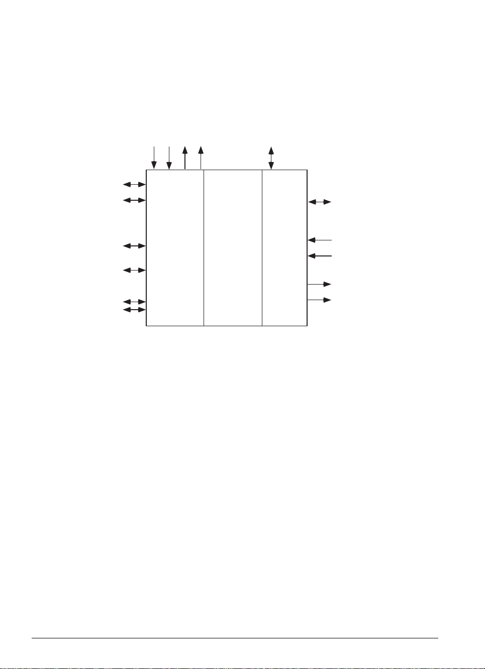
1 Hardware concept
The HEIDENHAIN-contouring controls TNC 407 and TNC 415 are designed for use with drilling and
milling machines.
The HEIDENHAIN-TNCs consist of several units. The principal subassembly is the logic unit. The logic
unit is joined to the other units and the TNC accessories by connecting cables.
Noml. value outputs
Encoders
• • •• • •
Visual display unit
TNC keyboard unit
PLC I/0 unit
Machine operating panel
Touch probe
Electronic handwheel
Data interfaces
NC
Common
data area
PLC
PLC inputs
• • •• • •
PLC outputs
The logic unit contains the electronics for both the NC and the PLC sections of the control.
The common data area contains the machine parameters and the PLC markers and words. The
machine parameters define the hardware configuration of the machine (ranges of travel, acceleration,
number of axes etc.). The PLC markers and words are used for the exchange of information between
the NC and the PLC.
2-2 TNC 407/TNC 415/TNC 425 1 Hardware concept 01.98
Page 7

2 Technical data TNC 407/TNC 415 B/TNC 425
TNC 407 TNC 415B/TNC 425
1
Axes 3, 4 or 5 plus spindle S
)
(NC axes and PLC axes can be defined as desired)
Program input In HEIDENHAIN Plain Language and to DIN/ISO
Memory for 6000 blocks approx. 12 000 blocks approx.
part program
Positions Nominal positions in Cartesian or polar coordinates,
dimensions absolute and incremental
Input and display to 1 µm to 0.1 µm
resolution
Interpolation
Linear interpolation 3 of 5 axes 5 of 5 axes
Circular interpolation 2 of 5 axes 3 of 5 axes
1)
Helix Yes
1
Rigid Tapping Yes
Block processing time
2
)
) 25 ms 4 ms
Look Ahead • Defined rounding of discontinuous contour transitions (e.g. 3D surfaces)
• Collision viewing with the SL cycle for "open" contours
• Advance calculation of geometry for feed-rate adjustment
Free contour In HEIDENHAIN Plain Language with graphic support
programming FK
Coordinate Shift and/or rotate coordinate system, mirroring, reduce and enlarge -
transformations also axis-specific
1
Tilting the – Yes
)
working plane
Subprogram Program section repeats, subprograms, program calls
functions
Fixed cycles Pecking, tapping, slot cutting, rectangular and circular pockets,
SL cycles (milling cycles whose contour descriptions are stored in
subprograms); the machine tool manufacturer can also integrate
1
customized macros
1)
These functions must be implemented by the OEM.
2)
3D-straight line without radius compensation
)
01.98 TNC 407/TNC 415/TNC 425 2 Technical data TNC 407/TNC 415 B/TNC 425 2-3
Page 8

TNC 407 TNC 415 B/TNC 425
Q-Parameters Mathematical functions (=, +, -, x, ÷, sin α, cos α, angle α from sin α
and cos α, a, a2 + b2, tan α, arcsin, arctan, arccos, an, en, ln,
log, absolute value of a number, the constant π, negation, truncate places
before or after the decimal point)
logical comparisons (=,≠, >, <),
Parenthetical calculations
Program test By graphic simulation of the part program
Parallel operation Yes, no graphics Yes, with graphics
File management up to 100 files: programs in HEIDENHAIN and DIN/ISO format, also tool 1),
PLC datum shift, pallet tables1) and text files
Tool compensation Tool length, tool radius in machining plane
– Three-dimensional tool
compensation with surface
normal vectors
Central tool file Various tool tables for 254 tools max. each, with flexible pocket coding,
tool life monitoring and sister tool organization
1)
Data interfaces V.24/RS 232 C and V.11/RS 422
•"Blockwise transfer": programs that exceed the control capacity can be
downloaded block by block and simultaneously executed.
• Extended data interface with LSV/2 protocol for external TNC operation
across the data interface
Baud rate 38 400; 19 200; 9 600; 4 800; 2 400; 1 200; 600; 300; 150; 110
Keyboard TE 400 with integral QWERTY keyboard
Screen BC 110 14" colour monitor 640 x 490 pixels
Logic unit LE 407 LE 415 B / LE 425
Axis control Feed pre-control or operation with servo lag
– TNC 425: additional digital speed control
Cycle times
Contour interpolation 6 ms 3 ms
Fine interpolation – TNC 415 B: 0.6 ms (contour)
TNC 425: 0.6 ms (speed)
Position control 0.1 µm
resolution
1)
These functions must be implemented by the OEM.
2-4 TNC 407/TNC 415/TNC 425 2 Technical data TNC 407/TNC 415 B/TNC 425 01.98
Page 9

TNC 407 TNC 415 B/TNC 425
Integral PLC
PLC inputs 56 + 1 "Control is ready" input; (Option: + 64
*
PLC outputs 31 + 1 "Control is ready" output "; (Option: + 31
.Two PL 410 max. can be connected
)
per PL)
*
)
per PL)
Option: analog inputs
1
)
± 10 V 4 per PL 410
or PA
Option: Inputs for
thermistors
1
4 per PL 410
)
or PA
PLC program memory Approx. 8 000 logic commands
PLC cycle time 24 ms 20 ms
Error compensation • linear axis error compensation
• non-linear axis error compensation
• compensation of reversal spikes in circular movements
• compensation of thermal expansion
• backlash compensation
• stiction compensation
• offset compensation
Position encoders HEIDENHAIN incremental linear and angle encoders (preferably with
distance-coded reference marks)
also HEIDENHAIN incremental rotary encoders
Reference mark Following a power interruption, automatic reference value input if
evaluation reference marks are traversed
Max. traverse ± 100 000 mm
Max. traversing 300 m/min
speed
Feed-rate and 0 to 150% with two potentiometers at the control panel
spindle override
Accessories
Electronic handwheel 1 x HR 330 Portable handwheel
or 1 x HR 130 Integral handwheel
or up to 3 x HR 150 Integral handwheel with adapter HRA 110
Diskette unit FE 401
Touch trigger 3D probe TS 120/TS 511
Measuring 3D probe — TM 110
Touch probe for tool TT 110
inspection
*)
PL 410 B: Active analog inputs reduce the number of PLC inputs by 8 and the number of PLC outputs by 2.
01.98 TNC 407/TNC 415/TNC 425 2 Technical data TNC 407/TNC 415 B/TNC 425 2-5
Page 10

TNC 407 TNC 415 B/TNC 425
Digitizing • With TS 120 touch trigger 3D probe
with optional software • With TM 110 measuring touch probe
module in TNC
Export versions TNC 415 F / TNC 425 E:
Linear interpolation 4 of 5 axes,
input/display resolution 1 µm
Power consumption
NC 24 W approx. 36 W approx.
PLC 6 W approx.
PL 410 B 25 W approx.
BC 110 B 70 W max.
Ambient
temperature
Operation 0 to 45°C
Storage –30 to 70°C
Weights
Logic unit 8.0 kg 10.0 kg
TE 400 2.4 kg
BC 110 B 11.0 kg
PL 410 B 3.1 kg
2-6 TNC 407/TNC 415/TNC 425 2 Technical data TNC 407/TNC 415 B/TNC 425 01.98
Page 11

3 Software
The logic unit contains separate software for the NC section and the PLC section. The software is
identified by an 8-figure number.
After switching on the control, the NC, PLC and Software-Options software numbers are displayed on
the screen. The software number can also be directly requested with the aid of the MOD function.
3.1 NC-Software
3.1.1 NC-Software number
The 8-figure NC software number identifies the type of control, the dialog language (language of the
country) and the version of the software.
259 96 0 01
Software type
National language
0 = German
1 = Czech
2 = French
3 = Italian
4 = Spanish
6 = Swedish
7 = Danish
8 = Finnish
9 = Dutch
Software version
In addition to the above-listed languages, the TNC can always use English, which may be selected via
the machine parameter MP7230.
3.1.2 Software types
Due to restrictions on the export of the TNC 415 B, HEIDENHAIN can also deliver a special export
version. This export version is differentiated from the standard control through the installed software
type. With this software type, the control offers different features in respect of linear interpolation and
the entry/display resolutions.
Linear interpolation Entry/Display
Resolution
TNC 415 B (Standard) 5 of 5 axes up to 0.1 µm
TNC 415 F (Export) 4 of 5 axes up to 1 µm
The TNC 407 does not fall under the export restrictions, therefore no export version is necessary.
01.98 TNC 407/TNC 415/TNC 425 3 Software 2-7
Page 12
New functions will be introduced only in the following software types:
TNC 415B / TNC 425: 280 54
TNC 415F / TNC 425 E: 280 56
TNC 407: 280 58
These software types are therefore supplied as standard.
3.1.3 Software option
HEIDENHAIN offers the "Digitising with TS 120" function as a software option (see chapter "Machine
integration"). An additional software protection module is installed in controls supplied with this
software option. The Id.-Nr. of the logic unit indicates another version. If the software module is
installed, the option is indicated on the screen under the NC and PLC software numbers.
Logic units that have already been delivered can be retrofitted with the software protection module.
Please contact HEIDENHAIN if you wish to buy this option for your existing control. The proper
component model must be ordered for a specific hardware model.
Digitizing with TS 120:
Id.-Nr. of the installation kit Id.-Nr. of software module NC software
TNC 407 265 313 01 243 02, 243 03, 280 58
TNC 415A 265 314 01 246 051 01 259 96
TNC 415B
TNC 425
286 405 01 280 54
Digitizing with TM 110:
Id.-Nr. of the installation kit Id.-Nr. of software module NC software
TNC 415B
TNC 425
2-8 TNC 407/TNC 415/TNC 425 3 Software 01.98
286 405 02 246 051 03 280 54
Page 13

3.1.4 Software/Hardware
Various hardware versions of the logic units LE 407 and LE 415 have until now been delivered (please
refer to the chapter 3 ”Mounting and electrical installation” section 1). The new software types are not
compatible with all hardware versions. The valid combinations are shown in the following tables.
TNC 415A / TNC 415E:
Software Type
Id.-Nr. LE 243 05 259 91 259 96 259 97
251 481 78
251 481 79 415 A - - X 251 481 88 415 E - X - X
251 481 89 415 A X - X 251 481 98 415 E - X - 251 481 99 415 A X - - 258 993 78 415 E - - - X
258 993 79 415 A - - X 258 993 88 415 E - X - X
258 993 89 415 A X - X 258 993 98 415 E - X - X
258 993 99 415 A X - X 264 429 78 415 E - - - X
264 429 79 415 A - - X 264 429 98 415 E - X - X
264 429 99 415 A X - X -
415 E
---X
TNC 415B / TNC 415F: TNC 425 / TNC 425E:
Id.-Nr.: 267 223 xy Id.-Nr.: 267 214 xy
x = Identifier for hardware change
y = Version
3 = Export version with software module "Digitizing with TS 120"
4 = Standard version with software module "Digitizing with TS 120"
7 = Standard version with software module "Digitizing with TS 120"
8 = Export version without option
9 = Standard version without option
01.98 TNC 407/TNC 415/TNC 425 3 Software 2-9
Page 14
TNC 407:
Software Type
Id.-Nr. of the LE 243 07 243 02 243 03 280 58
256 113 99 X - - 255 444 79 - X X X
255 444 89 X X X X
255 444 99 X X X X
261 092 79 - X X X
261 092 89 X X X X
261 092 99 X X X X
264 430 24 X X X X
264 430 29 X X X X
264 430 79 - X X X
264 430 99 X X X X
2-10 TNC 407/TNC 415/TNC 425 3 Software 01.98
Page 15
3.2 PLC-Software
The PLC software is produced by the manufacturer of the machine. Either HEIDENHAIN or the
manufacturer of the machine can store this software in EPROMs. HEIDENHAIN assigns PLC software
numbers to the machine manufacturers on request. HEIDENHAIN can archive the specific PLC
programs in a data bank, so that the installation of the correct PLC program is assured if a control has
to be exchanged.
The PLC EPROM must be written in the format of the corresponding software type!
Beginning with software types 280 54, 280 56 and 280 58, either a 1 MB or a 2 MB
EPROM can be used for the PLC.
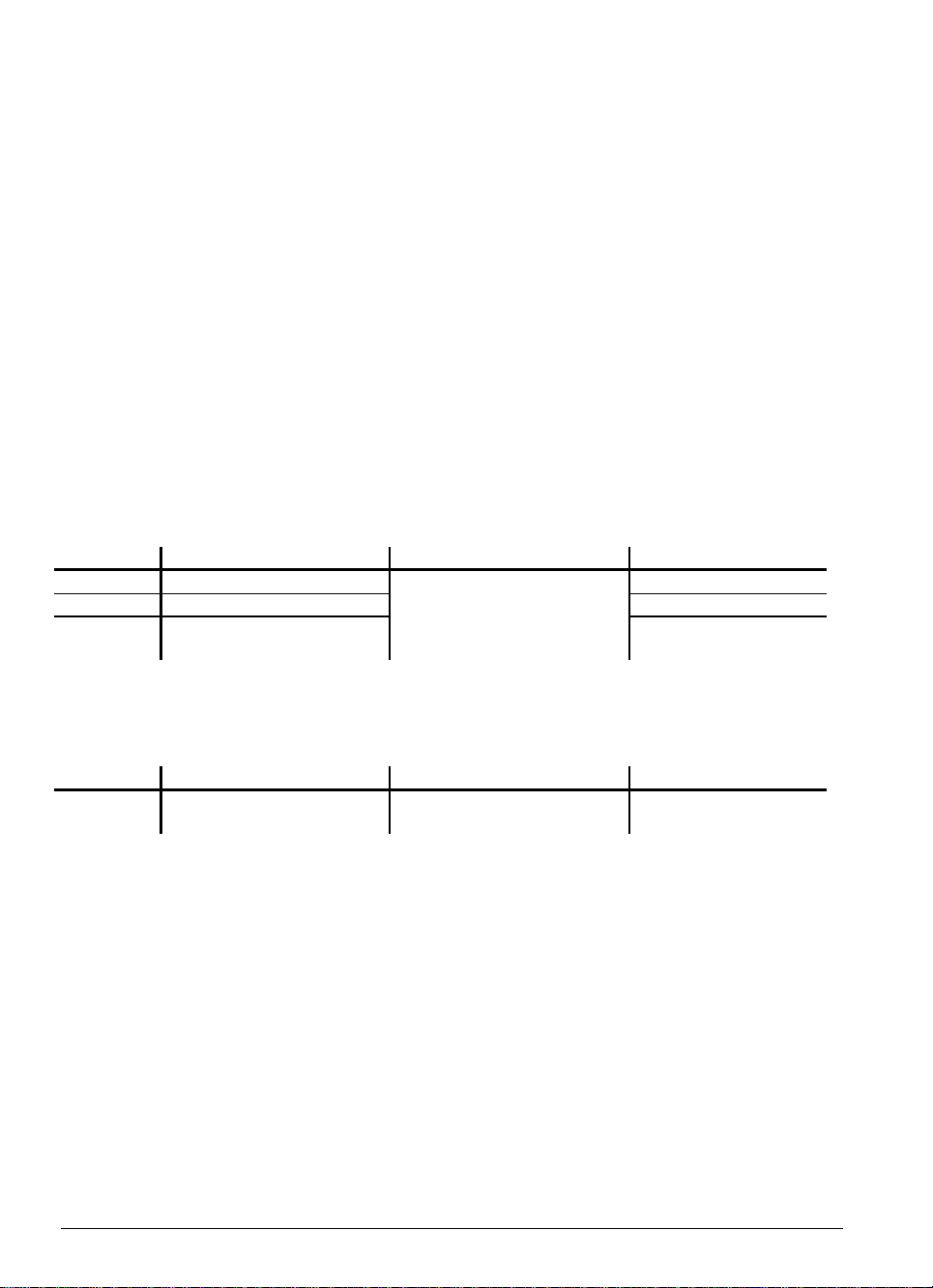
3.3 EPROM sockets
3.3.1 TNC 415 A/TNC 415 E
Sockets on processor board:
IC 3
NC
Sockets on CLP board:
1 MB 1 MB
IC 1 IC 2
1 MB 1 MBNC 1 MB 1 MB
IC 4
NC
NC
IC S
SW-Module
IC 8
PLC
IC 7
Language
IC 5
NC
1 MB
1 MB
IC 6
NC
IC 9
Boot
01.98 TNC 407/TNC 415/TNC 425 3 Software 2-11
Page 16
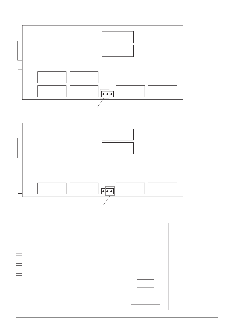
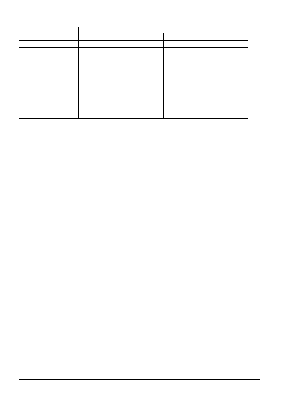
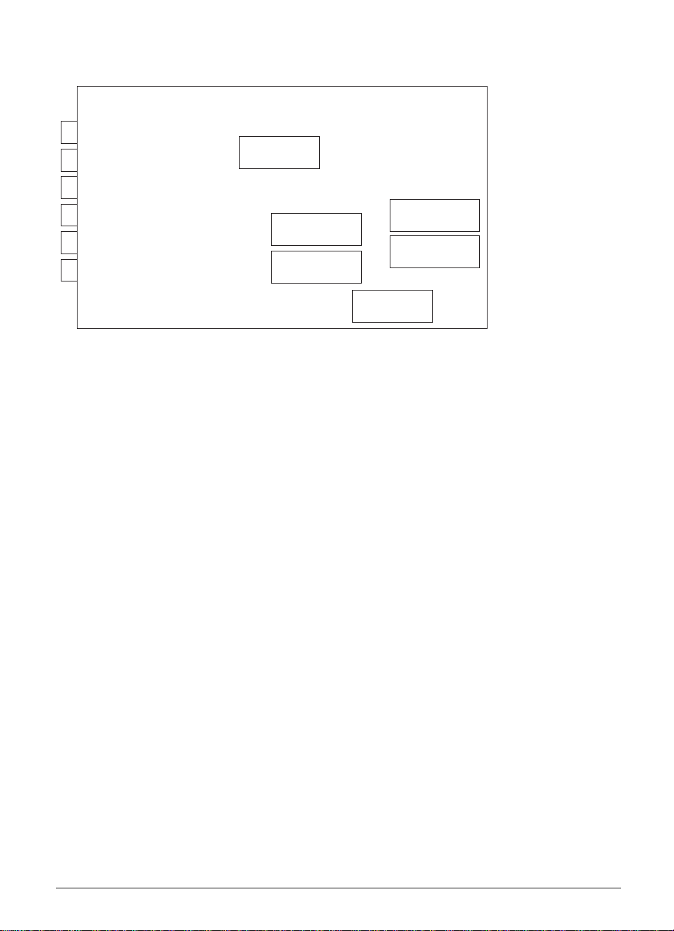
3.3.2 TNC 415 B/TNC 415 F and TNC 425 A/TNC 425 E
Sockets on processor board:
IC 3
NC
or
Sockets on processor board:
1 MB 1 MB
IC 1 IC 2
2 MB 2 MBNC 1 MB 1 MB
IC 4
NC
NC
Set jumper to 2M
IC 8
PLC
IC 7
Language
NC
IC 8
PLC
IC 7
Language
1 MB
1 MB
IC 5
1 MB
1 MB
IC 6
NC
IC 1 IC 2
4 MB 4 MBNC 1 MB 1 MB
Sockets on CLP board:
2-12 TNC 407/TNC 415/TNC 425 3 Software 01.98
NC
Set jumper to 4M
NC
IC 5
NC
IC 9
Boot
IC S
SW-Modul
IC 6
Page 17
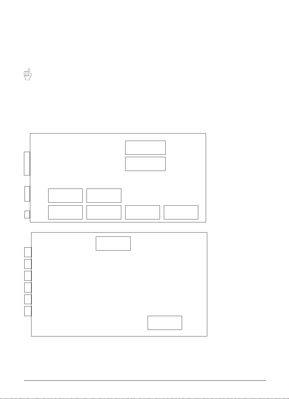
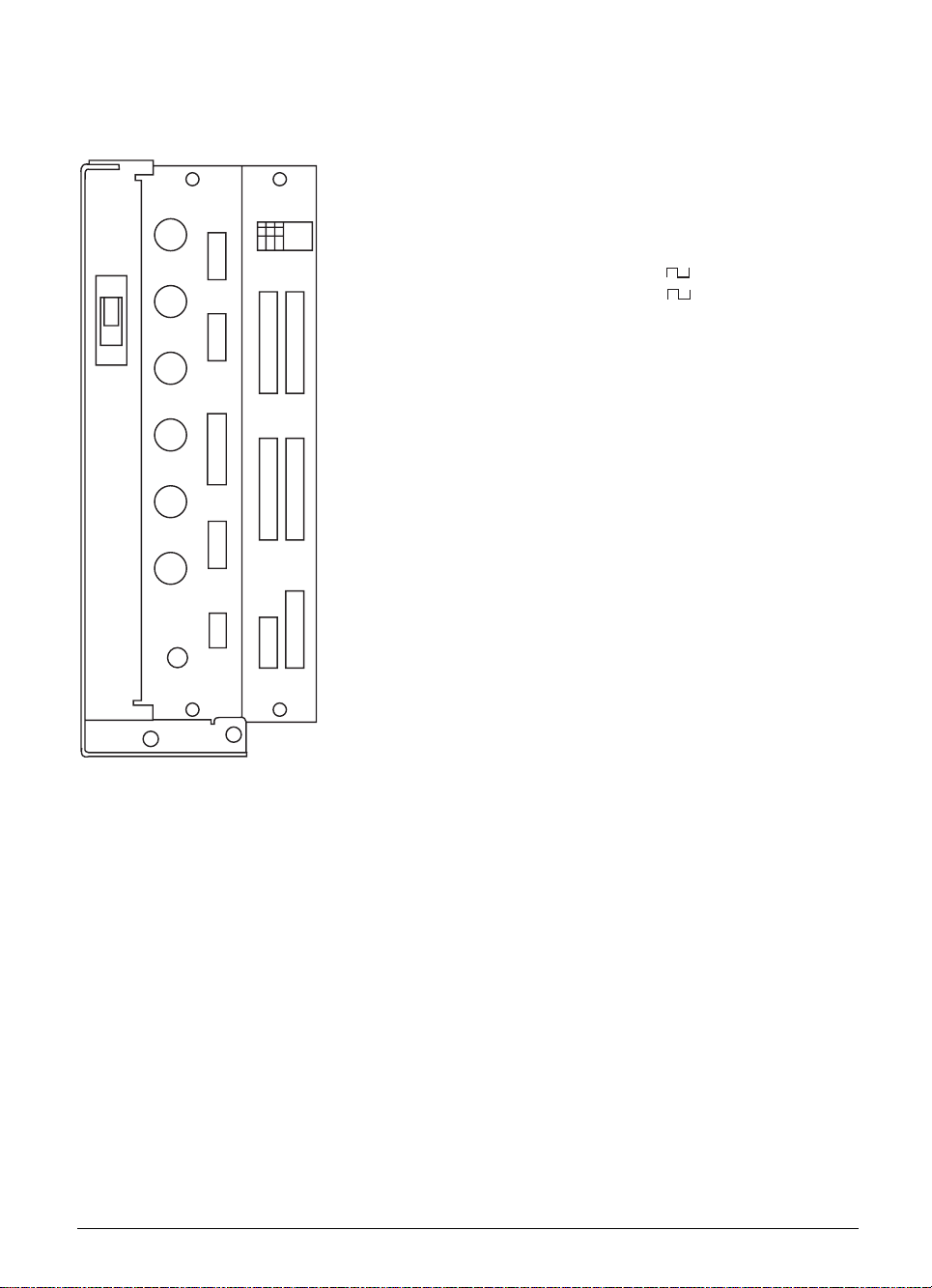
3.3.3 TNC 407
Sockets on processor board:
IC 5
PLC 1MB
IC 4
IC 3
Language
IC 1
1MB
Language
NC
2MB
IC S
SW-Module
1MB
IC 2
2MB
3.4 Software replacement
Before replacing the software on a TNC the data of all file types, the machine parameter list, the nonlinear axis error compensation table and the PLC program (if in the RAM) must be backed up.
You can use the TNC BACKUP routine to do this. In the "Machine Parameter Editor" mode (code
number 95 148) press the MOD key to display the menu for configuring the data interface. The
"BACKUP DATA" and "RESTORE DATA" soft keys will be offered.
Use "BACKUP DATA" to transmit all operating parameters and the data of all file types across the data
interface and store them in the $BACKUP.ANC file. When software replacement is complete, use
"RESTORE DATA" to download the data to the TNC again.
01.98 TNC 407/TNC 415/TNC 425 3 Software 2-13
Page 18

3.5 Releases
New NC software versions are released by HEIDENHAIN at irregular intervals.
3.5.1 Software types 243 05, 259 91 and 243 07
Standard version TNC 415 A
NC-Software-Version Release
243 05x 02 2/90
243 05x 03 4/90
243 05x 04 5/90
243 05x 05 8/90
243 05x 08 9/90
243 05x 10 2/91
243 05x 11 4/91
243 05x 12 5/91
243 05x 13 6/91
243 05x 14 11/91
243 05x 15 3/92
243 05x 16 7/93
TNC 407
243 07x 03 7/90
243 07x 05 10/90
243 07x 07 2/91
243 07x 08 4/91
243 07x 09 5/91
243 07x 10 6/91
243 07x 11 11/91
243 07x 12 3/92
243 07x 13 7/93
Export version TNC 415 E
NC-Software-Version Release
259 91x 08 11/90
259 91x 10 2/91
259 91x 11 4/91
259 91x 12 5/91
259 91x 13 6/91
259 91x 14 11/91
259 91x 15 3/92
259 91x 16 7/93
New releases of these software types will be
made only to correct errors.
3.5.2 Software types 259 96, 259 97 and 243 02
TNC 415 A: 259 96x 01
TNC 415 E: 259 97x 01
TNC 407: 243 02x 01 Release 8/91
New functions:
– Digitising with TS 120
– Rigid tapping
– Input resolution and display step 0.0001 mm for TNC 415 A
– Re-approaching the contour
– Compensation of reversal spikes in circular movements
– New format for PLC-EPROM
– Machine parameter editor
– FN15: PRINT
– New machine parameter for setting screen colours
2-14 TNC 407/TNC 415/TNC 425 3 Software 01.98
Page 19

– Thermal expansion compensation
– Machine datum
– "Free rotation"
– Changing the gear range through the PLC
– RPM upper limit per gear range
– Change in the organisation of PLC error messages
– Marker for special tool
– Interruption of PLC positioning
– Fast PLC input
– Arc end-point tolerance
– Locking of file types
– D596 rapid traverse from PLC
– D276 code number
– Axis-specific monitoring functions
– Compensation of tool length in the position display
– PLC: module 7031, module 9032, module 9083, module 9093, module 9094
TNC 415 A: 259 96x 02
TNC 415 E: 259 97x 02
TNC 407: 243 02x 02 Release 1/92
New functions:
– If MP7490 = 0, the datum is effective for all traverse ranges
– Non-linear characteristic curve for override potentiometer
– New process for traversing reference marks (MP1350.x = 3)
TNC 415 A: 259 96x 03
TNC 415 E: 259 97x 03
TNC 407: 243 02x 03 Release 3/92
New functions:
– ROT display in the status window
– PLC error messages if more than one of the markers M2485 to M2487 is set
– MP4070 has been added
– Handwheel symbol on screen for selected axis
– MP7640 (machine with handwheel) has new input values
– MP340 has been added (only for TNC 407)
– Module 9041 has been introduced (only for TNC 415 A)
– Dialog texts in Czech
01.98 TNC 407/TNC 415/TNC 425 3 Software 2-15
Page 20

TNC 415 A: 259 96x 04
TNC 415 E: 259 97x 04
TNC 407: 243 02x 04 Release 5/92
New functions:
– Multipoint axis error compensation: the maximum distance between compensation points was
increased to 2
– The maximum input range for position values was increased to –99 999.9999 mm to
+99 999,9999 mm.
– The override adjustment in 2 % steps was dropped.
– The minimum input value for MP6130 was changed to 1 mm and for MP6140 to 0.001 mm.
– MP440 was dropped.
– Mid-program startup (block scan) now works for ISO programs during blockwise transfer with
simultaneous execution.
New Module 9035
−
TNC 415 A: 259 96x 05
TNC 415 E: 259 97x 05
TNC 407: 243 02x 05 Release 5/92
New functions:
– The input value 4 was added to MP7480.
– The distance D to an auxiliary point with the coordinates PDX and PDY is now entered without
algebraic sign.
TNC 415 A: 259 96x 06
TNC 415 E: 259 97x 06
TNC 407: 243 02x 06 Release 9/92
New functions:
23
.
Electronic Handwheel mode
−
A new marker 2826 has been introduced. Setting this marker disables the evaluation of the
counting pulses received by the handwheel. The handwheel cannot be used to position when the
marker is set.
Transfer values to PLC
−
Numerical values can be entered in the new machine parameters MP4230.00 to MP4230.31 and
MP4231.0 to MP4231.31 which the PLC can read with module 9032.
MP4230.0 to MP4230.31 Transfer value to PLC with module 9032
MP4231.0 to MP4231.31
Entry: –99999.9999 to +99999.9999
DIN/ISO Programming
−
The maximum permitted length of an NC block in DIN/ISO has been increased from 130 to 150
characters.
2-16 TNC 407/TNC 415/TNC 425 3 Software 01.98
Page 21

TNC 415 A: 259 96x 07
TNC 415 E: 259 97x 07
TNC 407: 243 02x 07 Release 11/92
New functions:
Because it is run from standstill, the spindle orientation at the beginning of the "Rigid Tapping"
−
cycle is always executed in the direction of rotation that reaches the target by the shortest route.
Previously the direction of rotation with each spindle orientation was selected by marker M2656.
TNC 415 A: 259 96X 08
TNC 415 E: 259 97X 08
TNC 407: 243 02X 08 Release 1/93
New functions:
If the PLC simultaneously issues two commands from memory areas PLC positioning (M2704 to
−
M2708), confirm Q parameter (M2713) and PLC datum shift (M2716), then the NC flashes the
message "Error in PLC program 1R" as these commands use the same memory areas for data
transfer.
PLC positioning in more than one axis counts as a single command. If marker M2719 (switch-over
from word processing to TNC 355 mode) has the value 0, the same checks will be run with the
corresponding TNC 355 strobes.
TNC 415 A: 259 96X 09
TNC 415 E: 259 97X 09
TNC 407: 243 02X 09 Release 10/93
New functions:
Machine parameters MP951.x and MP7450 were introduced for calculating PLC positionings
−
during block scan.
01.98 TNC 407/TNC 415/TNC 425 3 Software 2-17
Page 22

3.5.3 Software types 259 93, 259 94 and 243 03
TNC 415 B/TNC 425: 259 93x 04
TNC 415 F/TNC 425 E: 259 94x 04 Release 11/92
New functions:
New functions for programmed contour approach and withdraw
−
"Working Plane" cycle for machines with swivel head
−
"Contour Train" cycle
−
"Scaling factor axis-specific" cycle
−
Three-dimensional tool compensation in DNC mode
−
Extended tool management
−
Extended additional status displays for file information, positions, tool data and coordinate
−
transformation
Stiction compensation
−
PLC axes
−
Extended PLC command set
−
Length of filenames increased to 16 characters
−
Automatic correction of centre offset for probe system
−
Oscilloscope function
−
New organization for PLC files
−
Additional machine parameters for data transfer to PLC
−
BACKUP and RESTORE functions
−
Q parameter for tool length (Q114)
−
Axis positions after programmed probe cycle in Q parameters Q115 to Q119
−
New input format for machine parameters
−
TNC 415 B/TNC 415: 259 93x 05
TNC 415 F/TNC 425 E: 259 94x 05 Release 11/93
New functions:
Status information can now be read with module 9035. See "TNC 407/TNC 415 B/TNC 425
−
Description of the Differences from TNC 415".
The minimum input range of machine parameters MP6120, MP6350, MP6360 has been changed
−
from 80 mm/min to 10 mm/min.
MP7300 has been extended as follows:
−
MP7300 Delete status display, Q parameter and tool data
Entry: 0 to 7
0 = delete status display, Q parameter and tool data when selecting a program
1 = delete status display, Q parameter and tool data with M02, M30, END PGM
and selecting a program
2 = delete status display and tool data when selecting a program
3 = delete status display and tool data with M02, M30, END PGM and selecting a
program
4 = delete status display and Q parameter when selecting a program
5 = delete status display and Q parameter with M02, M30, END PGM and
selecting a program
6 = delete status display when selecting a program
7 = delete status display with M02, M30, END PGM and selecting a program
2-18 TNC 407/TNC 415/TNC 425 3 Software 01.98
Page 23

TNC 407: 243 03x 05 Release 11/92
New functions:
All functions as for TNC 415 B except "Working Plane" cycle and three-dimensional tool compensation.
TNC 415 B/TNC 425: 259 93x 06
TNC 415 F/TNC 425 E: 259 94x 06
TNC 407: 243 03x 06 Release 12/92
New functions:
MP7411 is used to select whether to use the tool data (length, radius, axis) from the last TOOL
−
CALL block or from the calibrated data of the probe system in a touch probe block.
MP7411 Tool data in touch probe block
−
Entry: 0 or 1
0 =In the touch probe block the current tool data are overwritten with the
calibrated data of the probe system.
1 =Current tool data are retained even with a touch probe block.
The displayable area for FK graphics has been restricted to -30,000 mm to + 30,000 mm. The
−
maximum edge length is 30,000 mm.
TNC 415 B/TNC 425: 259 93X 07
TNC 415 F/TNC 425 E: 259 94X 07
TNC 407 243 03X 07 Release 3/93
New functions:
PLC module 9033 has been introduced. This module allows the user to select a particular machine
−
parameter file in a SUBMIT job and then execute a Reset so the control system boots up with this
MP file.
If the PLC simultaneously issues two commands from memory areas PLC positioning (M2704 to
−
M2708), confirm Q parameter (M2713) and PLC datum shift (M2716), then the NC flashes the
message "Error in PLC program 1R" as these commands use the same memory areas for data
transfer.
PLC positioning in more than one axis counts as a single command. If marker M2719 (switch-over
−
from word processing to TNC 355 mode) has the value 0, the same checks will be run with the
corresponding TNC 355 strobes.
The offset for a variable-speed spindle is now adjusted with a new algorithm. A single offset
−
adjustment is made two seconds after the nominal value has reached target position. Every
second thereafter the offset voltage is increased by 0.152 mV or decreased by 0.152 mV when
servo lag is greater or less than zero respectively, and if the voltage computed from the product of
servo lag and Kv factor is greater than 0.152 mV. This means that the offset voltage changes by 1
mV in 7 seconds approx.
01.98 TNC 407/TNC 415/TNC 425 3 Software 2-19
Page 24

TNC 415 B/TNC 425: 259 93x 08
TNC 415 F/TNC 425 E: 259 94x 08 This versions was supplied from 6/93 only when
TNC 407: 243 03x 08 expressly requested by the customer.
New functions:
LSV2 protocol
−
PLC axes
−
Help files
−
Synchronized axes
−
New compensation value table (simultaneous compensation of sag and ballscrew pitch error)
−
Cycle 3 "Slot Milling" modified
−
Cycle 27 "Cylinder Surface" new
−
"Working Plane": Displays are referenced to the tilted coordinate system; Touch probe functions in
−
the tilted coordinate system: Datum setting in the tilted system
M94 new (modulo 360°)
−
M103 new (reduced feed rate during plunge cutting)
−
M105/M106 new (second set of kv factors)
−
M112 new (Tolerance field for "Look ahead")
−
M116 new (feed rate for rotary axes in mm/min)
−
M118 new (Handwheel overlapping)
−
Min. and max. memory for DNC operation
−
Calculation with parentheses and expanded parameter functions
−
MP7470 was eliminated
−
Graphic depiction of the workpiece blank in the working space
−
M114 new (automatic compensation of machine geometry during machining with tilted axes)
−
Module 9150 new
−
Input/Output of tool and pocket tables
−
Module 9035 was expanded
−
TNC 415 B/TNC 425: 259 93x 09
TNC 415 F/TNC 425 E: 259 94x 09 This version was supplied from 8/93 only
TNC 407: 243 03x 09 when expressly requested by the customer.
New functions:
The export versions TNC 415F and TNC 425E were improved with linear interpolation in 4 of 5
−
axes (previously 3 of 5 axes).
TNC 415 B/TNC 425: 259 93x 10
TNC 415 F/TNC 425 E: 259 94x 10
TNC 407: 243 03x 10 Release 9/93
2-20 TNC 407/TNC 415/TNC 425 3 Software 01.98
Page 25

TNC 415 B/TNC 425: 259 93x 11
TNC 415 F/TNC 425 E: 259 94x 11 This version was supplied from 4/94 only
TNC 407: 243 03x 11 when expressly requested by the customer.
New functions:
The PLC module 9036 was expanded. The handwheel assignment can now be switched through
−
the PLC to any desired axis; the assignment is indicated in the status window by the position of
the handwheel symbol.
– After activation of Cycle 19 "Working plane" the offset is corrected only in the axis that is moved.
Previously the offset was corrected simultaneously in all axes during execution of the first block.
– With M112 it is now possible to enter a limit angle A in addition to the tolerance T.
TNC 415 B/TNC 425: 259 93x 12
TNC 415 F/TNC 425 E: 259 94x 12
TNC 407: 243 03x 12 Release 5/94
01.98 TNC 407/TNC 415/TNC 425 3 Software 2-21
Page 26

✎
2-22 TNC 407/TNC 415/TNC 425 3 Software 01.98
Page 27

3.5.4 Software types 280 54, 280 56 and 280 58
TNC 415 B/TNC 425: 280 54x 01
TNC 415 F/TNC 425 E: 280 56x 01
TNC 407: 280 58x 01 Release 6/94
New functions:
Digitizing with TM 110
−
– Program structuring
– Tool measuring with TT 110
– Complete NC block with Actual Position Capture key
– M124 new
TNC 415 B/TNC 425: 280 54x 02
TNC 415 F/TNC 425 E: 280 56x 02
TNC 407: 280 58x 02 Release 11/94
New functions:
– A “PLC” column was added to the tool table. As in the pocket table, relevant PLC data can be
entered here. This column is activated with machine parameter MP7266.17.
– A datum, tool, or pocket table can be searched for to certain values using Module 9092.
– The PLC can activate the geometry data of the tool from W264 with the new marker M2717.
– The elements “Number of cutting edges“, ”Tolerance for tool length”, “Tolerance for tool
radius”, “Cutting direction of the tool” and “PLC status” were added to Modules 9093 and 9094.
– During feed pre-control, the positioning window is not evaluated until the current velocity is less
than MP1525. In the previous software versions, the positioning window was not evaluated until
the velocity fell below 0.5 mm/min. Increasing the input value in MP1525 increases the block
processing time.
– Feed pre-control can be activated for all modes of operation with machine parameter MP1391.
This becomes necessary when stiction compensation is to be active in the manual modes of
operation.
– The maximum permissible positional difference between the two gantry axes is defined in
MP855. When this value is exceeded, the blinking error message GROSS POSITIONING ERROR
<AXIS> # A appears. The current positional deviation appears in the LAG display of the slave
axis.
– Module 9171 makes it possible to orient the spindle at a rotational speed defined by the PLC.
– Modules 9040 and 9041 make it possible to read coordinates referenced to a shifted coordinate
system.
– The jog increment can now be limited with Module 9036.
– With the new marker M2827 an EMERGENCY STOP (control-is-ready PLC input signal) can be
suppressed and, instead, all control loops opened and an NC stop executed.
– The new marker M2830 opens all control loops and stops the NC.
– In a digitized data file that has been produced with the TM 110 touch probe, the BLK FORM is
enlarged in the working plane by double the value of the deflection depth (MP6310).
– The radius compensation in the working plane is now also effective in NC blocks with 5-axis
interpolation. The NC block can contain, besides the three non-parallel linear axes, also two rotary
axes.
– Tool measurement with the TT 110 is possible only on machines with controlled spindle
(Spindle orientation).
01.98 TNC 407/TNC 415/TNC 425 3 Software 2-23
Page 28

TNC 415 B/TNC 425: 280 54x 03
TNC 415 F/TNC 425 E: 280 56x 03
TNC 407: 280 58x 03 This version was never released.
TNC 415 B/TNC 425: 280 54x 04
TNC 415 F/TNC 425 E: 280 56x 04
TNC 407: 280 58x 04 Release 3/95
New functions:
− To make changes to the tool table it is no longer necessary to transfer the entire tool table. It now
suffices to transfer only those tool data that have changed. These partial data can be transferred in
the Program Run mode of operation
− For a rotary table display that is set to modulo 360°, the M function M 126 positions the table by
the shortest path. M 127 positions the table, as before, by the path that does not cross over the 0°
position.
The function for automatic tool measurement was expanded with the TT 110. The new fields
L-OFFS, R-OFFS, LBREAK and RBREAK were introduced to the tool table (MP7266.19 to MP7266.21).
In addition, in Cycle 31 the radius is no longer entered and the fields L-OFFS, R-OFFS, LBREAK and
RBREAK were added to the modules 9092, 9093 and 9094. The new marker M2393 is set whenever
the break tolerance is exceeded.
2-24 TNC 407/TNC 415/TNC 425 3 Software 01.98
Page 29

TNC 415 B/TNC 425: 280 54x 05
TNC 415 F/TNC 425 E: 280 56x 05
TNC 407: 280 58x 05 Release 3/96
Improvements:
− The Polish dialog language was added, Id. Nr. 280 590 xx, 280 550 xx and 280 570 xx.
− Contour Pocket cycle (cycle 6, 15, 16, 21, 22, 23, 24)
MP7420
Bit 4 = 0: After the contour pocket is machined, the TNC moves to the position that was
last approached before the cycle was called.
Bit 4 = 1: After the contour pocket is machined, the TNC moves the tool to clearance height.
− Module 9036 Limiting jog increment
Transferred value:
0 to 50 mm = Limiting jog increment
–1; <–2 or >50 = Jog increment limit is canceled and the last increment entered is
activated.
–2 = Jog increment limit is canceled and the minimum from the last
increment entered and the last limiting value is activated.
TNC 415 B/TNC 425: 280 54x 06
TNC 415 F/TNC 425 E: 280 56x 06
TNC 407: 280 58x 06 Release 5/96
Improvements:
− MP1925 Limit for integral factor of the speed controller new.
01.98 TNC 407/TNC 415/TNC 425 3 Software 2-25
Page 30

2-26 TNC 407/TNC 415/TNC 425 3 Software 01.98
Page 31

Mounting and electrical installation – Contents 3
1 Hardware components 3-4
1.1 Changes in the ID-number 3-6
2 Assembly hints 3-9
2.1 Electrical noise immunity 3-9
2.2 Heat generation and cooling 3-9
2.3 Humidity 3-10
2.4 Mechanical vibration 3-10
2.5 Mounting position 3-10
2.5.1 Logic unit 3-11
2.5.2 Visual display unit (VDU) 3-13
2.6 Degree of protection 3-13
3 Summary of connections 3-14
3.1 TNC 415 3-14
3.2 TNC 407 3-15
4 Power supply 3-16
4.1 Logic unit and PLC I/O-board 3-16
4.1.1 NC power supply 3-16
4.1.2 PLC power supply 3-17
4.1.3 Buffer battery 3-18
4.2 Visual display unit (VDU) 3-19
4.3 Earthing plan 3-20
5 Measuring systems 3-24
5.1 Linear measuring systems 3-24
5.2 Angular measuring systems 3-24
5.3 Measuring system inputs for sinusoidal signals (7 to 16 µApp) 3-25
5.3.1 Connector assignments 3-25
5.3.2 Connecting cable 3-25
5.4 Measuring system inputs for square-wave signals 3-26
5.4.1 Connector assignments 3-26
5.4.2 Connecting cable 3-26
5.5 Measuring system connections 3-28
6 Nominal value output 3-32
6.1 Connector assignment 3-32
6.2 Connecting cable 3-32
7 Reference pulse inhibit input 3-35
7.1 Connector assignment 3-35
7.2 Connecting cable 3-35
01.98 TNC 407/TNC 415/TNC 425 3-1
Page 32

8 Touch probe system input 3-36
8.1 Connector assignment X12 3-36
8.2 Connection of the touch probe system 3-37
8.2.1 TS 120 3-37
8.2.2 TS 511 3-38
8.2.3 TM 110 3-39
9 Data interface 3-40
9.1 RS-232-C/V.24 data interface 3-40
9.2 RS-422/V.11 data interface 3-41
10 Handwheel input 3-43
10.1 Pin assignment 3-43
10.2 Portable handwheel HR 330 3-43
10.3 Integral handwheel HR 130 3-44
10.4 Portable handwheels with permissive buttons 3-45
10.5 Handwheel adapter HRA 110 3-49
11 PLC inputs/outputs 3-51
11.1 Technical data 3-52
11.1.1 PLC inputs 3-52
11.1.2 PLC outputs 3-52
11.1.3 Analog inputs 3-53
11.1.4 Inputs for Pt 100 thermistors 3-53
11.2 Connector assignment 3-54
11.2.1 PLC inputs 3-54
11.2.2 PLC outputs 3-55
11.2.3 PL connection 3-55
11.3 Connector assignment on the PL 3-56
11.3.1 Connection to LE or PL #1 3-56
11.3.2 Connection of PL #2 3-56
11.3.3 PLC inputs/outputs on the PL 400 3-57
11.3.4 PLC inputs/outputs on the PL 410 / PL 410 B 3-59
11.3.5 Analog inputs on the PL 410 / PL 410 B 3-60
11.3.6 Inputs for thermistors on the PL 410 / PL 410 B 3-60
11.4 Connector assignment on the PA 110 3-61
11.5 Connecting cable 3-61
11.5.1 Connection of PLC inputs/outputs on the LE 3-61
11.5.2 PL 400 connection 3-62
11.5.3 PL 410 / PL 410 B connection 3-62
11.5.4 PA 110 connection 3-62
11.5.5 Connection to analog inputs 3-63
11.5.6 Connection to inputs for thermistors 3-63
3-2 TNC 407/TNC 415/TNC 425 01.98
Page 33

12 Machine control panel 3-65
12.1 Pin connections 3-66
12.2 Connecting cable 3-67
13 TNC keyboard 3-68
13.1 Pin connections 3-68
13.2 Connecting cable 3-69
14 VDU 3-70
14.1 Pin connections 3-70
14.2 Connecting cable 3-70
14.3 Connecting the BC 120 3-71
15 Cable overview 3-72
16 Dimensions 3-74
16.1 LE 407 3-74
16.2 LE 415 3-75
16.3 TE 400 3-76
16.4 BC 110 B 3-77
16.5 PLC expansion boards 3-78
16.6 Cable adapters 3-81
16.7 Handwheels 3-84
16.7.1 HR 130 integral handwheel 3-84
16.7.2 HR 150 3-87
16.7.3 Portable handwheel HR 330 3-88
16.7.4 Portable handwheel HR 332 3-89
16.7.5 Portable handwheel HR 410 3-90
16.7.6 Handwheel adapter HRA 110 (for HR 150) 3-91
16.8 TT 110 for tool calibration 3-92
16.9 MB 410 3-93
16.10 MB 420 3-94
16.11 TE 400 B 3-95
16.12 BC 120 3-96
01.98 TNC 407/TNC 415/TNC 425 3-3
Page 34

1 Hardware components
The TNC 415B consists of the following hardware components:
. LE 415B (Logic unit),
. TE 400 (TNC keyboard),
. BC 110 B (Visual display unit),
. PL 410 B (max. 2 PLC-I/O boards, optional).
The export version which is offered is the TNC 415 F. In the TNC 415 F, an LE 415F is delivered in
place of the LE 415B. The export software is built into the LE 415 F.
The TNC 407 consists of the following hardware components:
. LE 407 A (Logic unit),
. TE 400 (TNC keyboard),
. BC 110 B (Visual display unit),
. PL 410 B (max. 2 PLC I/O boards, optional).
The TNC 407 is not subject to export restrictions. An export version is not required.
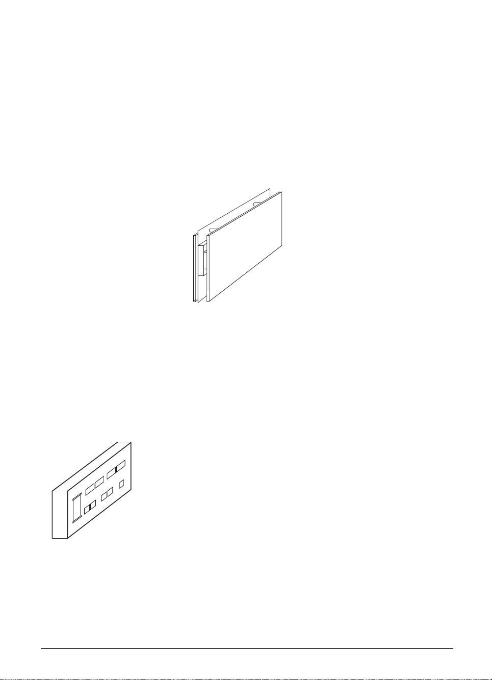
. Logic unit
LE 415 B (Id.-Nr. 267 223 ..) LE 407 A (Id.-Nr. 264 430 ..)
. TNC keyboard . VDU
TE 400 (Id.-Nr. 250 517 03) BC 110 B (Id.-Nr. 260 520 01)
Joined to the logic unit via 14 inch colour VDU with soft keys.
connecting cable. Joined to the logic unit and the TNC keyboard
via connecting cable.
3-4 TNC 407/TNC 415/TNC 425 1 Hardware components 01.98
Page 35
. PLC I/O unit (Option)
PL 410 B without analog inputs
(Id.-Nr. 263 371 12)
64 PLC inputs
31 PLC outputs
1 “Control is operational” output
Connected with the logic unit by cable. No more than two PL 410 B can be connected to the LE.
. PLC analog board (Option)
PL 410 B with analog inputs
(Id.-Nr. 263 371 02)
56 PLC inputs
29 PLC outputs
4 analog inputs ± 10V
4 inputs for Pt 100 thermistors
1 “Control is operational” output
PA 110 (Id.-Nr. 262 651 01)
Connected with the logic unit via cable or with
the first PLC I/O unit.
4 analog inputs for ± 10 V DC
4 analog inputs for Pt100 thermistors
01.98 TNC 407/TNC 415/TNC 425 1 Hardware components 3-5
Page 36

1.1 Changes in the ID-number
If development or manufacturing requirements make it necessary to alter any of the hardware
components, HEIDENHAIN will change the ID-numbers of the hardware components.
ID-Numbers assigned to date:
. VDU:
Id.-Nr. 254 740 01 BC 110 Separate power- until 5/91
supply for fan
Id.-Nr. 260 520 01 BC 110 B Power supply for since 11/90
fan taken from
VDU supply
. PLC-I/O board:
Id.-Nr. 252 855 01 PL 400 since 2/90
Id.-Nr. 263 371 01 PL 410 since 10/92
Id.-Nr. 263 371 02 PL 410 B with analog inputs
(5 V interface) since 10/94
Id.-Nr. 263 371 12 PL 410 B without analog inputs
(5 V interface) since 10/94
. TNC keyboard:
Id.-Nr. 250 517 01 TE 400 since 2/90
Id.-Nr. 250 517 03 TE 400 with APPR/DEP key since 9/92
3-6 TNC 407/TNC 415/TNC 425 1 Hardware components 01.98
Page 37

. Logic unit LE 415:
Id.-Nr. Logic unit Change
251 481 99 LE 415 until 12/90
251 481 89 LE 415 Colour graphics chip; since 9/91
Expansion slot for software module since 9/91
251 481 88 LE 415 E Export version of the Id.-Nr. 251 481 89
251 481 79 LE 415 Like Id.-Nr. 251 481 89, but with since 9/91
software module
251 481 78 LE 415 E Export version of the Id.-Nr. 251 481 79 since 9/91
258 993 99 LE 415 Changed power supply and since 11/90
graphics chip
258 993 98 LE 415 E Export version of Id.-Nr. 258 993 99 since 11/90
258 993 89 LE 415 Expansion slot for software module since 9/91
258 993 88 LE 415 E Export version of Id.-Nr. 258 993 89 since 9/91
258 993 79 LE 415 Like Id.-Nr. 251 481 89, but with since 9/91
software module
258 993 78 LE 415 E Export version of Id.-Nr. 258 993 79 since 9/91
264 429 99 LE 415 Expansion slot for software module since 6/91
264 429 98 LE 415 E Export version of Id.-Nr. 264 429 99 since 6/91
264 429 79 LE 415 Like Id.-Nr. 264 429 99, but with since 9/91
software module
264 429 78 LE 415 E Export version of Id.-Nr. 264 429 79 since 9/91
267 223 29 LE 415 B New processor board since 9/92
267 223 28 LE 415 F Export version of Id.-Nr. 267 223 29 since 9/92
267 223 24 LE 415 B Like Id.-Nr. 267 223 29
but with software module since 9/92
267 223 23 LE 415 F Export version of Id.-Nr. 267 223 24
267 223 39 LE 415 B Hardware change since 2/93
267 223 38 LE 415 F Export version of Id.-Nr. 267 223 39 since 2/93
267 223 34 LE 415 B Like Id.-Nr. 267 223 39
but with software module since 2/93
267 223 33 LE 415 F Export version of Id.-Nr. 267 223 34 since 2/93
267 223 49 LE 415 B Uninterruptible supply to since 5/93
control panel
267 223 48 LE 415 F Export version of Id.-Nr. 267 223 49 since 5/93
267 223 44 LE 415 B Like Id.-Nr. 267 223 49, but with since 5/93
software module
267 223 43 LE 415 F Export version of Id.-Nr. 267 223 44 since 5/93
01.98 TNC 407/TNC 415/TNC 425 1 Hardware components 3-7
Page 38

. Logic unit LE 407:
Id.-Nr. Logic unit Change
256 113 99 LE 407 A Pilot lot 32-bit bus until 9/90
255 444 99 LE 407 A 16-bit bus; colour graphics chip 8/90 until 5/91
255 444 89 LE 407 A Expansion slot for software module since 9/91
255 444 79 LE 407 A Like Id.-Nr. 255 444 89, but with since 9/91
software module
261 092 99 LE 407 A 32-bit bus since 5/91
261 092 89 LE 407 A Expansion slot for software module since 9/91
261 092 79 LE 407 A Like Id.-Nr. 261 092 89, but with since 9/91
software module
264 430 99 LE 407 A Expansion slot for software module since 6/91
264 430 79 LE 407 A Like Id.-Nr. 264 430 99 but with since 9/91
software module
264 430 29 LE 407 A Uninterruptible supply to control panel since 5/93
264 430 24 LE 407 A Like Id.-Nr. 264 430 29 but with since 5/93
software module
3-8 TNC 407/TNC 415/TNC 425 1 Hardware components 01.98
Page 39

2 Assembly hints
2.1 Electrical noise immunity
Please note that the vulnerability of electronic equipment to noise increases with faster signal
processing and higher sensitivity.
Please protect your equipment by observing the following rules and recommendations.
Noise voltages are mainly produced and transmitted by capacitive and inductive coupling. Electrical
noise can be picked up by the inputs and outputs to the equipment, and the cabling.
Likely sources of interference are:
– Strong magnetic fields from transformers and electric motors,
– Relays, contactors and solenoid valves,
– High-frequency equipment, pulse equipment and stray magnetic fields from switch-mode
power supplies,
– Mains leads and leads to the above equipment.
Electrical interference can be avoided by:
– A minimum distance between the logic unit (and its leads) and interfering equipment > 20 cm.
– A minimum distance between the logic unit (and its leads) and cables carrying interference
signals > 10 cm.
(Where signal cables and cables which carry interference signals are laid together in metallic
ducting, adequate decoupling can be achieved by using a grounded separation screen)
– Screening according to DIN VDE 0160.
– Potential compensating lines-∅ ≥ 6 mm² (see earthing plan).
– Use of original HEIDENHAIN cables, connectors and couplings.
2.2 Heat generation and cooling
Please note that the reliability of electronic equipment is greatly reduced by continuous operation at
elevated temperatures. Please make the necessary arrangements to keep within the permissible
ambient temperature range.
Permissible ambient temperature in operation: 0° C to 45° C
The following means may be employed to ensure adequate heat removal:
– Provide sufficient space for air circulation.
– Build in a ventilator fan to circulate the air inside the control cabinet. The fan must reinforce the
natural convection. It must be mounted so that the warm air is extracted from the logic unit
and no pre-warmed air is blown into the unit. The warmed-up air should flow over surfaces
which have good thermal conductivity to the external surroundings (e.g. sheet metal).
– For a closed steel housing without assisted cooling, the figure for heat conduction is 3 Watt/m²
of surface per °C air temperature difference between inside and outside.
– Use of a heat exchanger with separate internal and external circulation.
01.98 TNC 407/TNC 415/TNC 425 2 Assembly hints 3-9
Page 40

– Cooling by blowing external air through the control cabinet to replace the internal air. In this
case the ventilator fan must be mounted so that the warm air is extracted from the control
cabinet and only filtered air can be drawn in. HEIDENHAIN advises against this method of
cooling, since the function and reliability of electronic assemblies are adversely affected by
contaminated air (fine dust, vapours etc.). In addition to these disadvantages, a filter which is
not adequately serviced leads to a loss in cooling efficiency. Regular servicing is therefore
absolutely vital.
Incorrect
LE
Obstructive
elements
Heat generating
elements
Correct
LE
2.3 Humidity
Permissible humidity: < 75 % in continuous operation,
< 95 % for not more than 30 days p.a. (randomly distributed).
In tropical areas it is recommended that the TNC is not switched off, so that condensation is avoided
on the circuit boards. The heat generation prevents condensation and has no further disadvantages.
2.4 Mechanical vibration
Permissible vibration: < 0.5 g
2.5 Mounting position
Note the following fundamental points on mounting:
- mechanical accessibility,
- permissible environmental conditions,
- electrical noise immunity,
- the electrical regulations which are in force in your country.
3-10 TNC 407/TNC 415/TNC 425 2 Assembly hints 01.98
Page 41

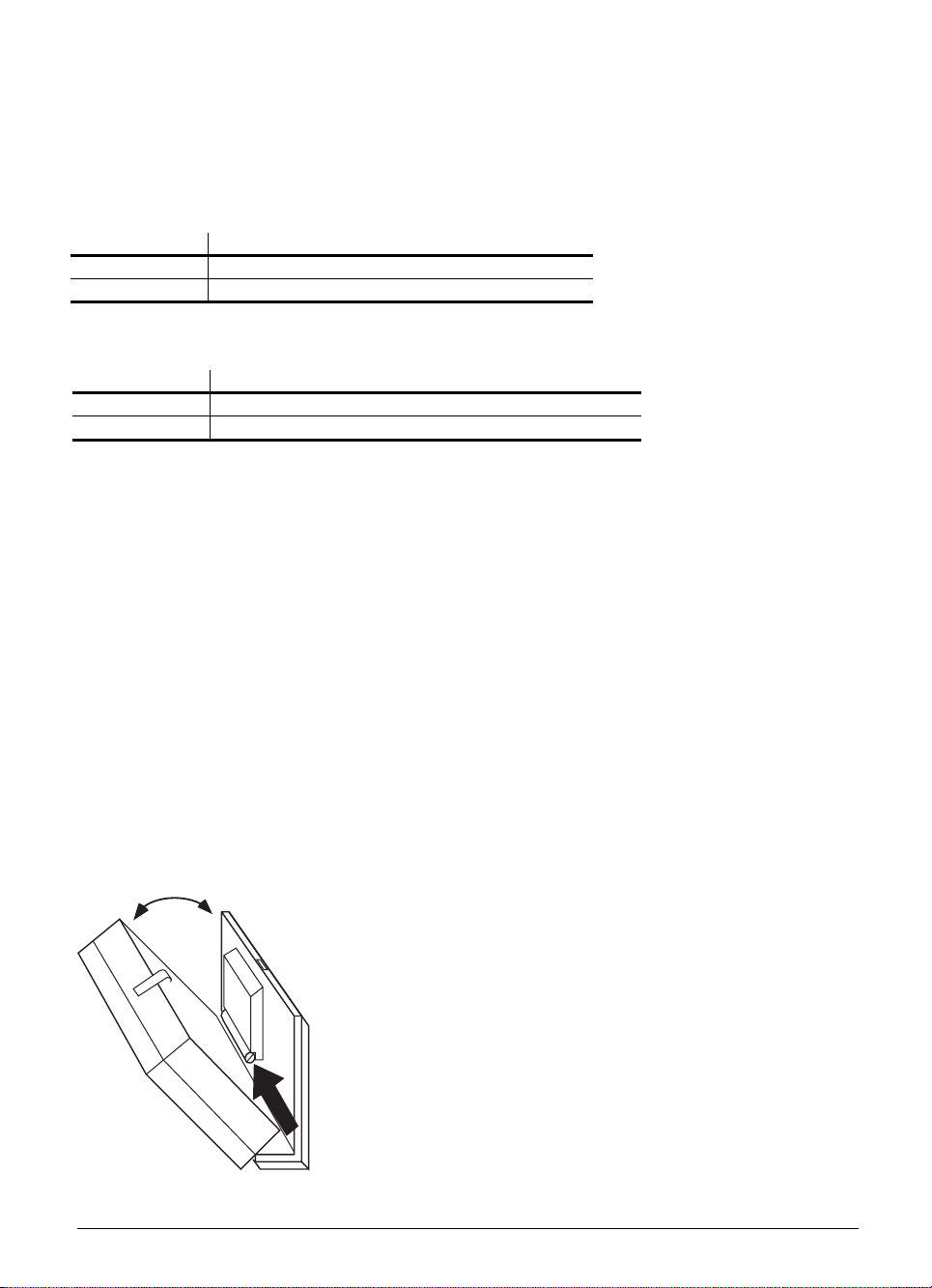
2.5.1 Logic unit
HEIDENHAIN recommends the following mounting position:
LE 407
>577
>110
Minimum clearance
for servicing!
recommended: =
approx. 250 mm
Maintain clearance
for screwdriver
Connecting cables
must not hinder
swivel movement
of the control
160
83
40
*
246
°C
30
60
40
80
80
40
°C
Air outlet
*
°C
*
°C
100
30
*
160
°C
*
Air inlet
°C
*
*
°C
Measuring point for
ambient temperature
Free space for air circulation
Free space for servicing
30
100
PL
°C
*
40
40°
40
01.98 TNC 407/TNC 415/TNC 425 2 Assembly hints 3-11
R 325
270
Illustration of
max. swivel range.
The minimum angle of
swivel for exchange
of subassembly should
be at least 90°.
145
Page 42

LE 415
>577
>110
Minimum clearance
for servicing!
recommended: =
approx. 250 mm
Maintain clearance
for screwdriver
Connecting cables
must not hinder
swivel movement
of the control
195
83
286.5
30
60
40
80
°C
Air outlet
* *
°C
*
Air inlet
°C
*
80
40
°C
30
°C
*
160
*
°C
Measuring point for
ambient temperature
Free space for air circulation
100
30
100
°C
40
*
40°
*
270
PL
°C
R 325
40
40
3-12 TNC 407/TNC 415/TNC 425 2 Assembly hints 01.98
Free space for servicing
Illustration of
max. swivel range.
The minimum angle of
swivel for exchange
of subassembly should
be at least 90°.
145
Page 43

2.5.2 Visual display unit (VDU)
When mounting the VDU it must be remembered that this unit is very sensitive to magnetic pick-up.
The picture position and geometry can be disturbed by stray magnetic fields. Alternating fields cause
periodic movement or distortion of the picture.
For this reason, keep a minimum distance of 0.5 m between the VDU casing and the source of any
disturbance (e.g. permanent magnets, motors, transformers etc.)
25
60
415
25
°C
*
*
°C
*
*
°C°C
60
25
25
15
330
20
25
°C
*
40
110
Measuring point for
°C
*
ambient temperature
Free space for air circulation
400
°C
°C
*
*
75
2.6 Degree of protection
When mounted, the visual display unit and the keyboard unit provide class IP54 protection against
dust and splashwater.
01.98 TNC 407/TNC 415/TNC 425 2 Assembly hints 3-13
Page 44

3 Summary of connections
3.1 TNC 415
24V
X31
X14
X8
X1
X2
X3
X4
X44
X41 X45
X21
X42 X46
Control-loop board colour code
X1 = Measuring system 1 (~)
X2 = Measuring system 2 (~)
X3 = Measuring system 3 (~)
X4 = Measuring system 4 (~)
X5 = Measuring system 5 (~)
X6 =
Measuring system S (
X8 = Nominal value - output
1, 2, 3, 4, 5, S
X10 = Reference pulse inhibit
X12 = Touch trigger probe
X14 = Measuring touch probe
B = Signal ground
)
X12
X5
X22
X6
X47
X43
X23
B
PLC and graphics board
X41 = PLC output
X42 = PLC input
X43 = VDU-screen (BC)
X44 = Power supply 24 V for PLC
X45 = TNC-keyboard (TE)
X46 = Machine control panel
X47 = PLC I/O board (PL)
Processor board
X21 = Data interface RS-232-C/V.24
X22 = Data interface RS-422/V.11
X23 = Electronic handwheel
X31 =
Power supply 24 V
DC for NC
3-14 TNC 407/TNC 415/TNC 425 3 Summary of connections 01.98
Page 45
3.2 TNC 407
X1
24V
X31
X2
X3
X4
X5
X12
X8
X21
X44
X41 X45
X42 X46
Processor board
X1 = Measuring system 1 (~)
X2 = Measuring system 2 (~)
X3 = Measuring system 3 (~)
X4 = Measuring system 4 (~)
X5 =
Measuring system 5 (
X6 =
Measuring system S (
X12 = Triggering touch probe
X8 = Nominal value - output
1, 2, 3, 4, 5, S
X21 = Data interface RS-232-C/V.24
X22 = Data interface RS-422/V.11
X23 = Electronic handwheel
B = Signal ground
)
)
X6
B
X22
X23
X43
X47
PLC and graphics board
X41 = PLC output
X42 = PLC input
X43 = VDU (BC)
X44 = Power supply 24 V for PLC
X45 = TNC keyboard (TE)
X46 = Machine control panel
X47 = PLC I/O board (PL)
X31 =
Power supply 24 V
DC for NC
01.98 TNC 407/TNC 415/TNC 425 3 Summary of connections 3-15
Page 46
4 Power supply
4.1 Logic unit and PLC I/O-board
LE NC
section
PLC
section
Supply
voltage
24 Vdc
24 Vdc
2)
3)
Voltage range
DC average
Lower limit
20.4 V
- - -
Lower limit
31 V
- - -
PL 410 B Digital
inputs/out
puts
Analog
24 Vdc
2)
inputs
PA 110 24 Vdc
1)
Voltage surges up to V
2)
VDE 0160, 5.88 low-voltage electrical separation
3)
VDE 0160, Base insulation
3)
for t < 100 ms are permissible.
- - -
4.1.1 NC power supply
The NC section of the LE must not be supplied
from the machine control voltage supply! It
requires an individual, external and separately
generated supply voltage according to VDE
0160, 5.88 recommendations for low-voltage
separation.
Max. current
consumption
LE 415: 1.5 A
LE 407: 1.3 A
2 A
1)
when half of the
inputs/outputs
are switched on
simultaneously
20 A
when half of the
inputs/outputs
are switched on
simultaneously
Power
consumption
LE 415: ≈ 36 W
LE 407: ≈ 24 W
≈ 48 W
when half of the
inputs/outputs are
switched on
simultaneously
≈ 480 W
when half of the
inputs/outputs
are switched on
simultaneously
≈ 100 mA ≈ 2.4 W
≈ 100 mA ≈ 2.4 W
U
24 V
1.5 V
pp
Use 24 V DC with a permissible AC component
of 1.5 V
(recommended filter capacitor 10 000
PP
t
µF/40 V DC).
X31 power supply for NC
Connection terminals
Pin Number Assignment
1 + 24 V DC
20 V
3-16 TNC 407/TNC 415 4 Power supply 01.98
Page 47

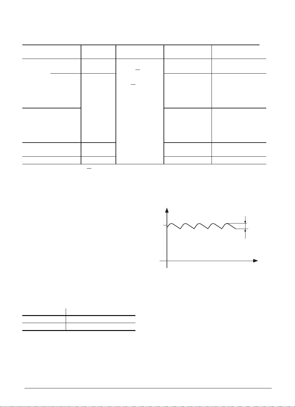
4.1.2 PLC power supply
The PLC section (PLC inputs and outputs) of the LE and PL is run from the 24 V machine control
voltage supply, generated according to VDE 0160 (base insulation). Superimposed AC components,
such as those caused by a three-phase bridge rectifier without smoothing, are permissible up to a
ripple factor of 5 % (see DIN 40110/10.75, Section 1.2).
U
32.6 V
31 V
20.4 V
18.5 V
t
The 0 V-line of the PLC-power supply must be grounded with an earth lead (∅ ≥ 6 mm2) to the main
frame ground of the machine. The earth lead at the frame of the PL 410 must be directly connected
to protective earth with an earth lead (∅ ≥ 6mm²). To prevent ground loops, the measured voltage at
the analog inputs must not be grounded
X44 power supply for the PLC
Connection terminals
Pin Number Assignment
1
2
30 V
DC switched off by EMERGENCY STOP
+ 24 V
DC not switched off by EMERGENCY STOP
+ 24 V
Power supply for the PL 400
Terminal Assignment
X13
X12 0 V
X3 Pin 12
Power supply for the PL 410
Terminal Assignment PL #1 or PL #2
X9 0V
X10 +24 V logic supply and for "Control ready"
X11 +24 V supply for outputs O32 - O39 or O64 - O71
X12 +24 V supply for outputs O40 - O47 or O72 - O79
X13 +24 V supply for outputs O48 - O55 or O80 - O87
X14 +24 V supply for outputs O56 - O62 or O88 - O94
The routing and connection of the thermistors and analog inputs must be shockproof to VDE 0160
(Section 5.5.1). If this cannot be guaranteed, then both the PLC and the PL 410 must be supplied
with voltage in accordance with VDE 0160, 5.88 recommendations for low-voltage electrical
separation.
01.98 TNC 407/TNC 415 4 Power supply 3-17
DC switched off by EMERGENCY STOP
+24 V
DC not switched off by EMERGENCY STOP
+ 24 V
Page 48
Power supply for the PL 410 B
Connections as on the PL 410, plus power supply at X23 in accordance with VDE 0160, 5.88 low-voltage
electrical separation for analog inputs (the NC power supply can be used).
X23 Power supply for analog inputs
Connection terminals
Pin Number Assignment
1 + 24 V DC
20 V
Power supply for PA 110
Pin Number Assignment
1 +24 V DC Not switched off by EMERGENCY STOP
20 V
The power for the PA 110 can be supplied according to VDE 0550, provided that the analog inputs
and connections for the Pt 100 are shockproof according to VDE 0160 (Section 5.5.1). If this is not
possible, the entire PLC power supply and the power for the PA 110 must be provided according to
VDE 0551.
4.1.3 Buffer battery
The buffer battery is the potential source for the RAM memory for NC-programs, PLC-programs
and machine parameters when the control is switched off.
If the
”EXCHANGE BUFFER BATTERY”
message appears, the batteries must be exchanged.
The 3 batteries may be found behind a screw cap in the power supply section of the logic unit.
As well as the batteries, the logic unit contains an additional energy store, mounted on the
processor board, for buffering the memory contents. This means that the mains can be switched off
when replacing the batteries. The energy store will ensure that the memory is retained while the
batteries are exchanged.
Type of batteries:
Three AA-size batteries, leak-proof,
IEC-Designation "LR6"
3-18 TNC 407/TNC 415/TNC 425 4 Power supply 01.98
Page 49

4.2 Visual display unit (VDU)
X3 = Mains supply connection
Mains supply
voltage
Supply voltage range 85 to 132 V 170 to 264 V
Fuse rating F 3.15 A F 3.15 A
Frequency range 50 to 60 Hz
Power consumption 70 W
Connection Assignment
L1 Live (BK)
N Neutral (BL)
X4 = DC connections (only for BC 110, Id.-Nr. 254 740 01)
Pin Number Assignment
1 + 24 V
20 V
Power supply for integral fan:
The power supply for the fan must be connected separately to the BC 110 (Id.-Nr. 254 740 01).
The connection to the +24 V machine control voltage must be according to VDE 0550.
Permissible voltage range +18 to +28 V; power consumption 5 W at +24 V DC.
110 V 220 V
Protective earth (GN/YL)
The power supply for the fan is taken internally from X3 in the BC 110 B (Id.-Nr. 260 520 01). There
X4 is a DC output for test purposes (please do not connect!).
01.98 TNC 407/TNC 415 4 Power supply 3-19
Page 50

4.3 Earthing plan
LE - Power supply
VDE 0551
1
Selectable
connection
+24V-
0V
+24V-
X31
0V
1
2
*)
+5V
Insulated
0V
SI
stab. supply
voltages
0V
Power supply
Measuring voltage
X15 - 18
X23
1
2
X14
X13
X12
X11
X10
1234 6
5
Unit LE
X6X4X3X2X1
X5
Machine Encoders
3
Optoc.
PT 100
X19 - 22
12345
Unit PL 410B
SI
X44/1
SI
X44/2
X44/3
X47X1
0V
2
1
X2
Emergency stop
controlled
PLC - Powersupply
VDE 0550
3
+24V-
0V
X9
X7
X7
X8
8 x 1,2A
Emergency Stop
X8
8 x 1,2A
X8
8 x 1,2A
X3-X6
7 x 1,2A
64 Inputs
to 2nd PL
6mm
6mm
6mm
6mm
+24V-
+24V-
0V
2
2
B
2
2
1
0
*) In order to avoid an earth circuit, the measuring voltage should not be grounded. If it must be
grounded, ensure that the ground line is short and noise immune.
3-20 TNC 407/TNC 415/TNC 425 4 Power supply 01.98
Page 51

Triggering
touch probe
X12
Optoc.
Measuring
touch probe
X14
Operating panel
C
Optoc.
C
X21
X22
X23
X43
X45
X46
8 x24 Matrix
8 x 0,1A
24 Inputs
Adapter
V.24
Adapter
RS 422
Handwheel
Display
Unit
Keyboard
Unit
Machine
Op. Panel
4mm
2
X41 X41 X41 X41 X42
7x0,1A
Emergency Stop
6mm
6mm
6mm
6mm
6mm
2
2
2
2
2
0,1A
16x0,1A
8x0,1A
Test point 1
(Fault voltg. 0V/
housing)
32 Inputs
Terminal box
1,2,3,4,5
X8
(Spindle)
Spindle
C
C
L
C
V
C
B
V
Test Point 2
(Fault voltg. with
grounded nominal
value input)
To prevent earth circuits, the measuring
voltages should not be gruonded.
If it must be grounded,
ensure that the line is short and noise
immune.
A grounded nominal input results in an
earth circuit. Therefore ensure that the
0V and ground line are short and noise
immune.
0V
0V
1-Axis
2-Axis
3-Axis
4-Axis
5-Axis
(Spindle)
Motor control with
nominal value
difference input
Spindle
Motor control
without nominal
value difference
input
01.98 TNC 407/TNC 415/TNC 425 4 Power supply 3-21
Page 52

✎
3-22 TNC 407/TNC 415/TNC 425 4 Power supply 01.98
Page 53

✎
01.98 TNC 407/TNC 415/TNC 425 4 Power supply 3-23
Page 54

5 Measuring systems
The HEIDENHAIN-contouring controls are designed for the installation of incremental linear and
angular measuring systems.
The control controls the actual position with a measuring step of 0.0001 mm or 0.0001°. Measuring
systems and encoders with a graduation period of 0.001 mm or 0,001° to 0.1 mm or 0.1° may be
used.
It does not matter whether the measuring system or encoder has one or several reference marks.
However, HEIDENHAIN recommends the use of measuring systems with distance-coded reference
marks, since the traversing distance when referencing is thereby reduced to a minimum. See
Chapter "Machine Integration".
The current requirement per measuring system input must not exceed 300 mA. The maximum
current requirement for all measuring system inputs together is limited to 1.2 A.
5.1 Linear measuring systems
Measurement of length is best performed by a linear measuring system or encoder. Insofar as it is
compatible with the accuracy requirements, linear measurement can also be made using a rotary
encoder on the ballscrew.
HEIDENHAIN recommends use of the following linear measuring systems:
LS 103 C, LS 106 C, LS 405 C, LS 406 C, LS 706 C, LB 326, ULS 300 C.
For linear measurement with the aid of a rotary encoder and a ballscrew you could use, for example,
an ROD 450.
5.2 Angular measuring systems
For direct angular measurement in the A, B or C axes the following incremental angular measuring
systems are available: ROD 250 C, ROD 700 C, RON 255 C, and RON 705 C.
In order to meet accuracy requirements, HEIDENHAIN recommends line counts of at least
18 000.
3-24 TNC 407/TNC 415/TNC 425 5 Measuring systems 01.98
Page 55

5.3 Measuring system inputs for sinusoidal signals (7 to 16 µAPP)
The LE 415 can have five measuring systems and the LE 407 four measuring systems connected
with sinusoidal inputs (7 to 16 µA
). Maximum input frequency is 50 kHz.
pp
5.3.1 Connector assignments
LE 407: X1, X2, X3, X4 measuring system 1, 2, 3, 4
LE 415: X1, X2, X3, X4, X5 measuring system 1, 2, 3, 4, 5
Flange socket with female connector insert (9-pin)
Pin Number Assignment
1I
2I
5I
6I
7I
8I
3 + 5 V
40 V
9 Inner screen
Housing Outer screen = housing
+
1
–
1
+
2
–
2
+
0
–
0
5.3.2 Connecting cable
Please use only HEIDENHAIN measuring system cables, connectors and couplings. Standard
HEIDENHAIN extension cables enable a maximum distance of 60 m (200 ft) to be covered.
Measuring system
max. 30 m
With standard extension cable (Id.-Nr. 262 006 ..)
With armoured extension cable (Id.-Nr. 262 016 ..)
LE
01.98 TNC 407/TNC 415/TNC 425 5 Measuring systems 3-25
Page 56

5.4 Measuring system inputs for square-wave signals
One measuring system with square-wave signals can be connected to the LE 415. Two such
systems can be connected to the LE 407. Maximum input frequency is 300 kHz.
5.4.1 Connector assignments
LE 407: X5, X6 measuring system 5, S
LE 415: X6 measuring system S
Flange socket with female connector insert (12-pin)
Pin Number Assignment
5U
6U
8U
1U
3U
4U
7U
2 + 5 V (UP)
12 + 5 V (UP)
11 0 V (UN)
10 0 V (UN)
9 (contact spring) screen = housing
––—–
––—–
––—–
––—–
a1
a1
a2
a2
a0
a0
aS
5.4.2 Connecting cable
Please use only HEIDENHAIN-measuring system cables, connectors and couplings.
In order to be able to connect a measuring system to the square-wave signal input of the logic unit,
the sinusoidal signal from the measuring system must be converted to a square-wave signal. This
conversion is performed by the interpolation and digitizing electronics (EXE). The interpolation and
digitizing electronics is either integrated into the measuring system or made as an independent unit.
If the interpolation and digitizing electronics does not have its own power supply, it can be supplied
from the logic unit. In order to ensure a correct supply voltage, the total length of the connecting
cable between the interpolation and digitizing electronics and the logic unit must be limited (see the
following diagram).
3-26 TNC 407/TNC 415/TNC 425 5 Measuring systems 01.98
Page 57

Spindle orientation:
ROD 426.xxx8
1024 lines
ROD 271 C
RON 275 C
ROD 250 C
RON 255 C
ROD 700 C
RON 705 C
Angle encoders:
or:
Extension cable
Id.-Nr. 262 011 ..
max. 20 m
Extension cable
Id.-Nr. 262 011 ..
max. 20 m
EXE
602 E
5-fold
X6
LE
X5
LE 407
Extension cableExtension cable
Id.-Nr. 262 004 ..Id.-Nr. 262 006 ..
X5
LE 407
max. 10 m
Extension cable
Id.-Nr. 233 764..Id.-Nr. 262 006 ..
max. 50 m
X5
LE 407
ROD 250 C
RON 255 C
ROD 700 C
RON 705 C
max. 30 m
or:
Extension cable
EXE
801
5-fold
max. 30 m
If necessary, linear measuring systems can also be connected to the X5 connector on the LE 407 via
interpolation and digitizing electronics.
Spindle orientation
01.98 TNC 407/TNC 415/TNC 425 5 Measuring systems 3-27
Page 58

5.5 Measuring system connections
Please observe the directions in the assembly instructions for the particular measuring system
which is being employed.
Measuring system cables must be laid without any intermediate clamping. Please use only the
HEIDENHAIN-connectors and couplings for making connections.
Type Connector Coupling
Pin number Cable Ø
for PUR cable for PUR cable
7-pole
6 mm
8 mm
6 mm
8 mm
9-pole
6 mm
8 mm
6 mm
8 mm
12-pole
6 mm
8 mm
6 mm
8 mm
237 524 20
237 524 24
—
237 524 21
237 524 03
237 524 02
237 524 15
237 524 10
237 524 06
237 524 07
237 524 14
237 524 12
—
—
237 525 11
—
—
—
237 525 07
237 525 04
237 525 01
237 525 03
237 525 09
237 525 06
3-28 TNC 407/TNC 415/TNC 425 5 Measuring systems 01.98
Page 59
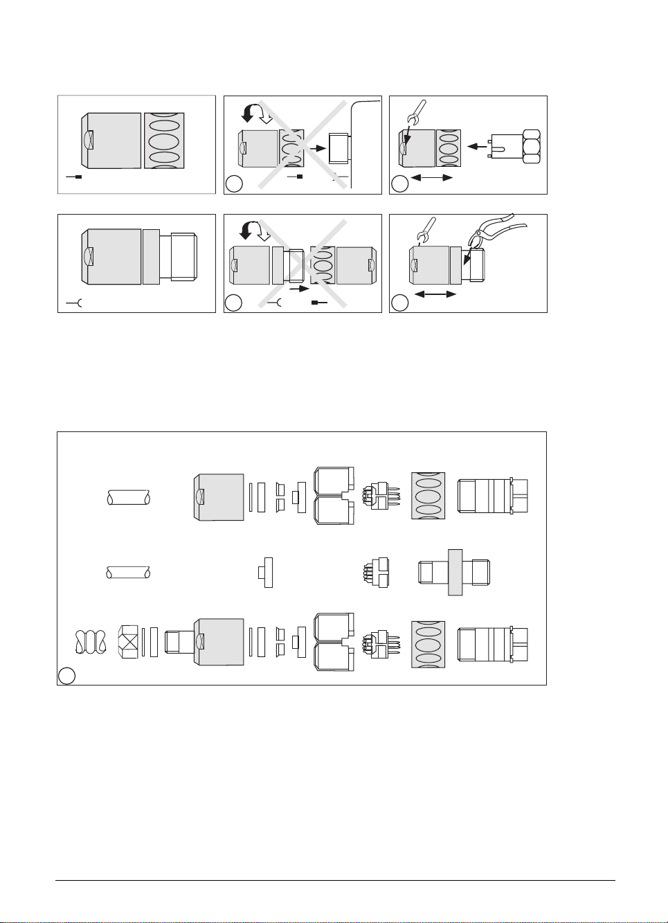
Assembly of the connector 237 524 ..
Assembly of the coupling 237 525 ..
2.
1.
1a 1b
3.
2.
1.
2a 2b
3.
1a + 2a Do not open connector or coupling with a mating connector!
1b The special assembly tool Id.-Nr. 236 148 01 and a 22 mm spanner are absolutely
necessary to assemble the connector.
2b An adjustable pipe-wrench with plastic jaws is required to assemble the coupling.
ABCDE F G H K
C1 G1 H1
ZYX A1
3
3 The diagram shows the various component parts of the connector and the coupling, and
the two different versions of the screw connections for the armoured version PG7 and
PG9. The screw connection PG9 with the Id.-Nr. 209 629 01, consisting of the parts X
Z
, must be ordered separately.
1
, Y1,
1
01.98 TNC 407/TNC 415/TNC 425 5 Measuring systems 3-29
Page 60

4
ABC
D
22
.87"
3
.12"
E
5
.20"
65
3
.12"
1.
2.
7 8
10
G
9
HK
F
4 Push parts A – D on to the cable, alternatively assemble the screw connection for the
armouring according to diagram 3. Strip back 22 mm of the outside sleeving. Unpick the
outer screen and fold back.
5 Cut off the outer screen to a length of 3 mm and slide the screen contact sleeve E
between the internal sleeving and the braided screen.
6 Cut back the internal sleeving to a length of 5 mm.
7 1. twist the inner screen together.
2. insulate the twisted inner screen with heat-shrinkable sleeving.
8 Strip off the insulation on all leads for 3 mm, tin and solder in accordance with the
connection diagram to G or G1.
9 Assemble part F.
10 Push the connector together.
The following points must be observed when assembling the measuring system:
.The inner screen (pin 9) must not make any electrical connection with the outer screen (connector
housing).
.The outer screen of the measuring system cable must have an electrical connection with the
connector housing.
.The measuring system is grounded through its mechanical fixings, the mounting block in the case
of encapsulated systems, and the housing of the scale.
.When using external pulse-forming electronics (EXE) the ground must be electrically connected
with the frame of the machine. Necessary cable cross-section ≥ ∅ 6 mm².
.Encapsulated linear measurement systems should be connected to compressed air.
3-30 TNC 407/TNC 415/TNC 425 5 Measuring systems 01.98
Page 61
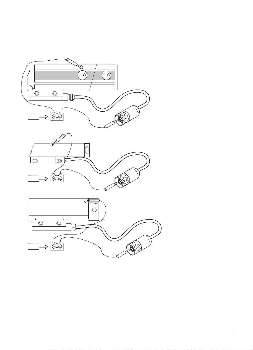
Please check that the mounting block, the sensor unit and the scale housing all have a good
electrical connection with the chassis/frame of the machine. Since the connector for the measuring
system and the mounting block are connected by the outer screen of the connector cable, this test
can be carried out between the measuring system connector and the measuring system housing.
During this test the connector must not be plugged in to the logic unit, as this would cause a
grounding via the logic unit.
<1Ω
<1Ω
•
•
•
•
LS 107 C
LS 403 C, LS406 C
<1Ω
LS 704 C
01.98 TNC 407/TNC 415/TNC 425 5 Measuring systems 3-31
Page 62

3
6 Nominal value output
HEIDENHAIN contouring controls control the position loop servo with a nominal value potential of
±10 volts.
Maximum loading of the nominal value outputs: 2 mA
Maximum load capacitance: 2 nF
6.1 Connector assignment X8
Id.-Nr. 290 110..
max. 20 m
Id.-Nr. 290 109..
BN
BN/GN
YL
RD/BL
PK
GY/PK
RD
VI
WH
WH/GY
GN
GY
BL
BK
•
1
2
3
4
5
6
7
8
9
10
11
12
13
14
15
X8 Nominal value output
1
Nominal value output 1
2
Do not use
3
Nominal value output 2
4
Nominal value output 5
5
Nominal value output 3
6
0V Nominal value output 5
7
Nominal value output 4
8
Nominal value output S axis
9
0V Nominal value output 1
10
Do not use
11
0V Nominal value output 2
12
Do not use
13
0V Nominal value output 3
14
0V Nominal value output 4
15
0V Nominal value output S axis
6.2 Connecting cable
HEIDENHAIN offers a connecting cable with a connector at one end (Id.-Nr. 290 109 ..).
The connecting cable to the nominal value outputs may not have more than one intermediate
terminal. The terminal must be made in an earthed connection box. This is necessary when the
cable must branch to physically separate servo inputs. It is only possible to earth the screening of
the servo leads in this way. If required, suitable connection boxes are available from HEIDENHAIN
with the Id.-Nr. 251 249 01.
3-32 TNC 407/TNC 415/TNC 425 6 Nominal value output 01.98
Page 63

The casing of the connection box must be electrically connected with the frame of the machine.
The 0 V of the nominal value differential input must be joined to signal ground, (cable cross-section ≥
Ø 6 mm², see also under "Earthing plan").
Suggested solution for connecting and wiring the screening in the connection box:
LE
•
Insulated against housing
Leads are provided
with end sleeves.
1 2 3 4 5 6 7 8 9 10 11 12 13 14 15 16
Cable screens are led onto 0.14 mm
•
Z
IV V
S
Y
X
insulated strands via crimp eyelets.
SERVO
Pin number Assignment
1 Nominal value output X axis
2 Nominal value output 0 V X axis
3 Nominal value output Y axis
4 Nominal value output 0 V Y axis
5 Nominal value output Z axis
6 Nominal value output 0 V Z axis
7 Nominal value output IV axis
8 Nominal value output 0 V IV axis
9 Nominal value output V axis
10 Nominal value output 0 V V axis
11 Nominal value output S axis
12 Nominal value output 0 V S axis
13 Screen connection
14 Screen connection
15 Screen connection
16 Screen connection
2
HEIDENHAIN recommends that the logic unit and the connection box be connected by
HEIDENHAIN-cable Id.-Nr. 290 109 ..
If the manufacturers want to use their own cable, HEIDENHAIN offers a 15 pin Sub-D connector
with solderable leads (Id.-Nr. 243 971 ZY).
01.98 TNC 407/TNC 415/TNC 425 6 Nominal value output 3-33
Page 64

✎
6 Nominal value output
3-34 TNC 407/TNC 415/TNC 425 6 Nominal value output 01.98
Page 65

7 Reference pulse inhibit input
The reference pulse inhibit input can be used to suppress the evaluation of the reference pulse input
of each of the six measuring systems. This is achieved by simply applying a positive potential (13 V
to +30.3 V) to the appropriate reference pulse inhibit input. Pin 9 of the female connector X10
(reference pulse inhibit) must be connected to 0 V of the PLC-power supply.
The reference pulse inhibit inputs are only available in the LE 415 A. These inputs are
normally unused. See also Chapter "Machine Integration".
7.1 Connector assignment X10
X10 Reference pulse inhibit (LE 415 A only)
Flange socket with female connector insert (9-pin)
Pin number Assignment
1 Screen
2 Reference pulse inhibit input X1
3 Reference pulse inhibit input X2
4 Reference pulse inhibit input X3
5 Reference pulse inhibit input X4
6 Reference pulse inhibit input X5
7 Reference pulse inhibit input X6
8 Do not use
9 0 V (PLC)
7.2 Connecting cable
Standard commercially available screened cables can be used for the connections to the reference
pulse inhibit inputs.
HEIDENHAIN can deliver a 9-pin D-subminiature connector (Id.-Nr. 244 503 ZY) for this purpose.
01.98 TNC 407/TNC 415/TNC 425 7 Reference pulse inhibit input 3-35
Page 66

8 Touch probe system input
The following 3D touch probe systems are available from HEIDENHAIN:
– TS 120 with cable transmission and integrated APE (interface electronics)
– TS 511 with infrared transmission of the trigger signal and connectable via APE (interface
electronics)
– TT 110 for workpiece measurement
– The TNC 415 and TNC 425 can also support the measuring touch probe system TM 110
For start-up and adjustment of the 3D-touch probe systems see Chapter "Machine Integration".
8.1 Connector assignment X12
X12 Touch probe system
D-subminiature female connector (15-pin)
Pin number Signal designation
1 Inner screen (0 V)
3 Ready/standby
4 Start
5 +15 V ± 10 % (UP)
6 + 5 V ± 5 % (UP)
7
8 0 V (UN)
9 Trigger signal
10
2, 11 to 15 Do not use
Battery warning
Trigger signal²
2
Stylus in rest position = signal high
3-36 TNC 407/TNC 415/TNC 425 8 Touch probe system input 01.98
Page 67
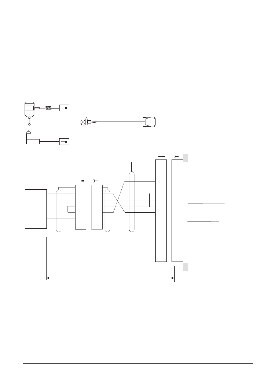
8.2 Connection of the touch probe system
Please use only HEIDENHAIN connecting cables and adapters for the connection to the touch probe
system.
8.2.1 TS 120 or TT 110
The touch probe system TS 120 is connected directly to the logic unit via a cable adapter.
See also under the heading "Mounting dimensions".
TS 120 helical cable
(extended 1.5 m)
Cable adapter complete
X12
Id.-Nr. 274 543..
TT 110 cable with
metal armour tubing
Touch probe inputs
•
1
1
2
2
Standby
3
3
4
4
+15V ±10% (U
5
5
+ 5V ± 5% (U
6
6
Battery warning
7
7
•
8
9
10
11
12
13
14
15
8
9
10
11
12
13
14
15
0V (U
N)
Trigger signal
Trigger signal
P)
P)
TS 120
or
TT 110
GY
WH
BN
GN
YL
PK
••
1
1
2
2
3
3
4
4
5
5
6
6
BN
GY
WH
GN
YL
max. 50 m
01.98 TNC 407/TNC 415/TNC 425 8 Touch probe system input 3-37
Page 68

8.2.2 TS 511
The TS 511 touch probe system can only function together with a transmitter/receiver unit (SE 510)
and interface electronics (APE 510).
SE 510
SE 510
Flash signal
IR-signal
Internal
screen (0V)
3 m
•
WH/
BK
WH
BN
GY
GN
0V
U
P
WH/
BK
•
max. 7 m max. 30 m
APE 510
1
APE
2
510
3
4
5
6
7
1
1
2
2
3
3
4
4
5
5
6
6
7
7
Id.-Nr. 274 540 ..
•
GY
YL
RD
BN
WH
GN
BL
Id.-Nr. 274 539 ..
••
7
5
3
2
6
1
4
GY
YL
BN
BL
WH
GN
WH/BN
X12
Touch probe input
•
1
1
2
2
3
3
4
4
5
5
6
6
7
7
8
8
9
9
10
10
11
11
12
12
13
13
14
14
15
15
Internal screen (0V)
Standby
Start
15V ±10% (U
Battery warning
0V (U
Trigger signal
P)
N)
The signals may be inverted by changing the switch positions S1 to S4 in the APE 510.
See operating instructions TS 511.
Please install the transmitter/receiver unit SE 510 either insulated from, or electrically connected to
the machine, as it must take up a definite potential, also under vibration. The earthing screw of
the APE 510 must be joined to the machine signal ground by a potential compensating lead
(≥ ∅ 6 mm²). See also under the heading "Earthing plan".
3-38 TNC 407/TNC 415/TNC 425 8 Touch probe system input 01.98
Page 69
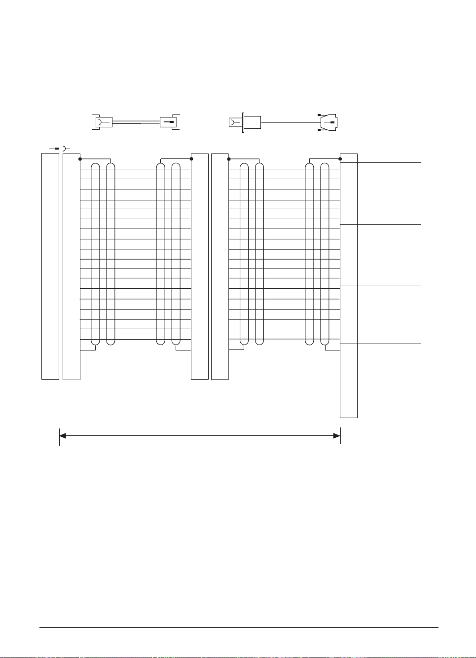
8.2.3 TM 110
The TM 110 measuring touch probe can be mounted to the TNC 415 B and TNC 425. A special
software module (optional) is required for digitizing with TM 110.
TM
110
17
11
10
15
16
13
12
19
18
21
14
20
Id.-Nr. 284 574 ..
Id.-Nr. 285 289 ..
X14 Measuring
touch probe TM 110
1
1
2
2
5
5
4
4
7
7
6
6
3
3
17
9
9
8
8
11
10
15
16
13
12
19
18
21
14
20
WH
BN
YL
GN
RD
BL
WH/BK
BN/BK
YL/BK
GN/BK
RD/BK
BL/BI
WH/VI
BN/VI
YL/VI
GN/VI
RD/VI
BL/VI
17
11
10
15
16
13
12
19
18
21
14
20
1
1
2
2
5
5
4
4
7
7
6
6
3
3
17
9
9
8
8
11
10
15
16
13
12
19
18
21
14
20
WH
BN
YL
GN
RD
BL
WH/BK
BN/BK
YL/BK
GN/BK
RD/BK
BL/BI
WH/VI
BN/VI
YL/VI
GN/VI
RD/VI
BL/VI
15
17
16
19
21
20
23
12
25
11
24
13
1
0V
+ 5V
I
–
4
1
Axis X
I
+
1
–
I
3
2
I
+
2
5
0V
+ 5V
8
–
I
1
Axis Y
+
I
1
–
I
7
2
I
+
2
0V
9
+ 5V
–
I
1
Axis Z
+
I
1
–
I
2
+
I
2
0V
2
6
10
14
18
22
max. 12m
01.98 TNC 407/TNC 415/TNC 425 8 Touch probe system input 3-39
Page 70

9 Data interface
The HEIDENHAIN contouring controls TNC 407 and TNC 415 have two data interfaces:
one RS-232-C/V.24 data interface and
one RS-422/V.11 data interface.
Both interfaces may be utilised. The operator decides which of the two interfaces he wishes to use.
See also chapter "Data interface".
9.1 RS-232-C/V.24 data interface
HEIDENHAIN guarantees that, if properly connected, the serial data interface RS-232-C/V.24 will
transmit data correctly up to a distance of 20 m between the logic unit and the peripheral unit.
The connection to the peripheral unit is made via a cable adapter which is attached to either the
operating console or the control cabinet. See also under the heading "Mounting dimensions".
This cable adapter (Id.-Nr. 239 758 01) is connected to the logic unit with the HEIDENHAIN cable Id.Nr. 239 760 ..
For connection to the peripheral unit HEIDENHAIN offers a standard connecting cable
(Id.-Nr. 274 545 01) , length 3 m.
Peripheral
unit
GND
TXD
RXD
RTS
CTS
DSR
GND
DTR
3 m
Id.-Nr. 274 545 01
WH/BN WH/BN WH/BN
•
1
1
2
3
4
5
6
7
8
9
10
11
12
13
14
15
16
17
18
19
20
•
2
3
4
5
6
•
7
8
9
10
11
12
13
14
15
16
17
18
19
20
WH/BN
GN
YL
GY
PK
BL
RD
BN
RS-232-C Adapter Block
Id.-Nr. 239 758 01
•
1
•
2
3
4
5
6
•
7
8
9
10
10
11
11
12
12
13
13
14
14
15
15
16
16
17
17
18
18
19
19
20
20
•
•
1
2
3
4
5
6
7
8
9
1
••
2
3
4
5
6
7
8
9
10
10
11
11
12
12
13
13
14
14
15
15
16
16
17
17
18
18
19
19
20
20
Id.-Nr. 239 760..
•
1
2
3
4
5
6
7
8
9
max. 17 m
YL
GN
PK
GY
BN
RD
BL
X21 Data interface RS-232-C/V.24
•
1
1
•
2
3
4
5
6
7
8
9
10
11
12
13
14
15
16
17
18
19
20
GND Chassis
2
RXD Receive data
3
TXD Transmit data
4
CTS Clear to send
5
RTS Request to send
6
DTR Data terminal ready
7
GND Signal ground
8
9
10
11
12
13
14
15
16
17
18
19
20
DSR Data set ready
If your peripheral unit has a connector layout that differs from the above, the HEIDENHAIN
connecting cable cannot be used.
3-40 TNC 407/TNC 415/TNC 425 9 Data interface 01.98
Page 71
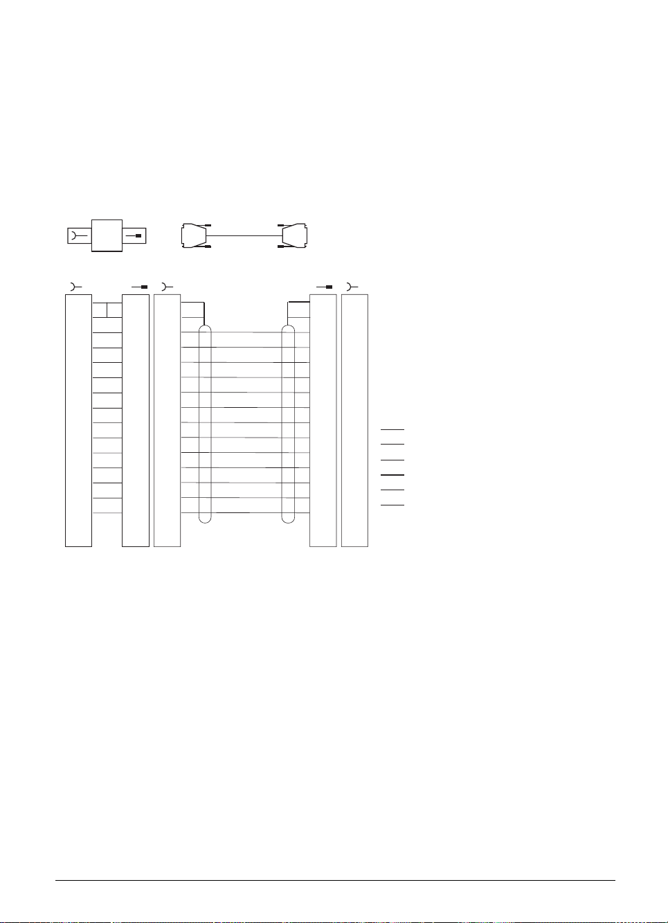
9.2 RS-422/V.11 data interface
If used correctly, the RS-422/V.11 serial data interface will ensure error-free data transmission up to
a distance of 1000 m between logic unit and peripheral unit.
The connection to the peripheral unit is made via a cable adapter which is attached to either the
operating console or the control cabinet. See also under the heading "Mounting dimensions".
The cable adapter is connected to the logic unit with a HEIDENHAIN connecting cable.
RS-422 Adapter Block
max. 1000 m
X22 Data interface
Id.-Nr. 249 819 01
Id.-Nr. 289 208 ..
RS-422/V.11
•
1
2
3
4
5
6
7
8
9
10
11
12
13
14
15
GND Chassis
RXD
CTS
TXD
RTS
DSR
DTR
GND Signal
RXD
CTS
TXD
RTS
DSR
DTR
1
•
BK
2
3
4
5
6
7
8
9
10
11
12
13
14
15
10
11
12
13
14
15
•
1
•
BK
2
3
4
5
6
7
8
9
BL
GY
WH
GN
WH/GN
GY/PK
BK
RD
PK
BN
YL
BN/GN
RD/BL
••
1
2
3
4
5
6
7
8
9
10
11
12
13
14
15
The pin assignment is the same at both ends of the connecting cable.
In the RS-422 adapter the pins of the female connectors are connected one-to-one.
The pin assignment in the cable adapter is therefore the same as in the X22 connector in the logic
unit.
The following cable type must be used for the connection to the peripheral unit:
LIYCY 7 x 2 x 0.14 Cu
For the cable connection HEIDENHAIN offers a 15-pin D-subminiature connector
(Id.-Nr. 243 971 ZY).
1
•
2
3
4
5
6
7
8
9
10
11
12
13
14
15
01.98 TNC 407/TNC 415/TNC 425 9 Data interface 3-41
Page 72

✎
3-42 TNC 407/TNC 415/TNC 425 9 Data interface 01.98
Page 73

10 Handwheel input
The following handwheels can be connected to the HEIDENHAIN contouring controls.
1 integral handwheel HR 130, or
3 integral handwheels HR 150 using handwheel adapter HRA 110, or
1 portable handwheel HR 330, or
1 portable handwheel HR 332
10.1 Pin assignment
X23 Handwheel input
D-subminiature female connector (9-pin)
Pin number Assignment
20 V
4
6 DTR
7 TxD
8 RxD
9 DSR
1, 3, 5 Do not use
+ 12 V ± 0.6 V (Uv)
10.2 Portable handwheel HR 330
The HR 330 is a portable handwheel with keys for the 5 axes, rapid traverse, direction of traverse
and EMERGENCY STOP.
The HR 330 is connected to the logic unit by means of the cable adapter Id.-Nr. 249 889 ..
See also under the heading "Mounting dimensions".
The HEIDENHAIN extension cable Id.-Nr. 281 429 .. may be used to increase the connection
distance.
The HR 330 is available in 2 versions:
. HR 330 helical cable (stretched length 2.2 m) Id.-Nr. 251 534 11
. HR 330.001 normal cable (max. 6 m) Id.-Nr. 251 534 12
Dummy plug for EMERGENCY STOP circuit Id.-Nr. 271 958 02
01.98 TNC 407/TNC 415/TNC 425 10 Handwheel input 3-43
Page 74

HR 330.001 max. 6 m
HR 330 max. 2.2 m
max. 48 m
max. 49 m
HR
Id.-Nr. 251 534..
EMERGENCY OFF
max. 24V
BL
HR 330
BL
GN
YL
BN
WH
•
The adapter includes a cable with a 9 pin connector from the connection to the logic unit and two
terminals for connecting the 24 V of the EMERGENCY STOP control circuit (max. load 1.2 A).
See also the Section "Mounting dimensions".
Adapter
HR 330
Id.-Nr. 249 889..
BL
2
BL
1
WH
1
1
2
2
3
3
4
4
5
5
6
6
•
•
BN
YL
GN
max. 50 m
1
2
3
4
5
6
7
8
9
Id.-Nr. 281 429 ..
••
1
2
3
4
5
6
7
8
9
WH
BN
YL
GN
•
1
2
3
4
5
6
7
8
9
Electronic
X23
handwheel
1
2
0V
3
4
+12V ± 0.6V(U
5
6
DTR
7
8
RXD
9
V)
10.3 Integral handwheel HR 130
The HR 130 is the integral version of the HR 330, without the keys for the axes, rapid traverse etc.
It may be attached directly to the logic unit, or via an extension cable (Id.-Nr. 249 814 ..).
The HR 130 (Id.-Nr. 254 040 ..) is available in several versions (standard cable length 1 m):
- small knob; axial cable exit: version 01
- small knob; radial cable exit: version 02
- large knob; axial cable exit: version 03
- large knob; radial cable exit: version 04
- ergonomic knob; radial cable exit: version 05
You will find dimension drawings for the knobs at the end of this chapter.
3-44 TNC 407/TNC 415/TNC 425 10 Handwheel input 01.98
Page 75

Adapter
HR 130
max. 6 m
Id.-Nr. 254 040..
max. 49 m
Id.-Nr. 281 429 ..
X23
Electronic
handwheel
•
1
1
2
2
3
4
5
6
7
8
9
0V
3
4
+12V ±0.6V (U
5
6
DTR
7
8
RXD
9
V
)
HR 130
WH
BN
YL
GN
••
1
2
3
4
5
6
7
8
9
max. 50 m
•
1
2
3
4
5
6
7
8
9
WH
BN
YL
GN
10.4 Portable handwheels with permissive buttons
HR 332
Handwheel HR 332 has two enable buttons and a keypad that can be evaluated by the PLC (see
"Handwheel" section in the chapter entitled "Machine Integration"). There are different models of the
handwheel with different key labelling - please contact HEIDENHAIN for further details.
HR 332 is connected to a cable adapter on the panel by means of a 5 m plug-in connecting cable.
The connecting cable is available with or without metal armouring.
Maximum cable length between HR and LE is 50 m.
Connecting cable to HR 332 Id.-Nr. 272 291 ..
Connecting cable to HR 332, with metal armouring Id.-Nr. 272 292 ..
Cable adapter HR 332/LE Id.-Nr. 274 556 ..
Extension cable for cable adapter Id.-Nr. 281 429 ..
Dummy plug for EMERGENCY STOP circuit Id.-Nr. 271 958 01
Handwheel holder Id.-Nr. 268 268 03
HR 332 Id.-Nr. 266 064 21
01.98 TNC 407/TNC 415/TNC 425 10 Handwheel input 3-45
Page 76

HR 332
HR 332
EM. STOP
EM. STOP
Permiss.
Perm. com.
Permiss.
6
TXD
RXD
Screen
DSR
0V
+12V
Id.-Nr. 272 292 ..
Id.-Nr. 272 291 ..
blue
1
pink
2
red
3
violet
4
black
5
x
6
green
7
grey
8
x
9
yellow
10
white
11
brown
12
Id.-Nr. 274 556 ..
3
2
1
2
1
••
1
1
2
2
3
3
4
4
5
5
6
6
•
7
7
8
8
9
9
10
10
11
11
12
12
Adapter
HR 332
black
violet
red
white
white
bl
white
rt
brown
x
yellow
grey
green
max. 50 m
Id.-Nr. 281 429 ..
••
1
2
3
4
5
6
7
8
9
bl
•
1
white
2
rt
3
brown
4
x
5
yellow
6
grey
7
green
8
9
X23
LE
X23
1
1
2
3
4
5
6
7
8
9
1
2
0V
3
3
4
+12V±0.6V(Uv)
5
5
6
DTR
7
TXD
8
RXD
9
The adapter has a cable with a 9-pin plug for connection to the logic unit, two terminals for the 24 V
of the EMERGENCY STOP circuit of the control (max. load 1.2 A) and 3 terminals for the enable
circuit. The enable buttons are N/O contacts (24 V/1.2 A).
HR 410
The HR 410 is a portable electronic handwheel with:
• Five axis-selection keys
• Traverse direction keys
• Three keys with predefined traverse speeds (slow, medium, fast)
• Actual-position-capture key
• Three keys for machine functions to be determined by the machine tool builder
• Two permissive buttons
• EMERGENCY STOP button
• Holding magnets
Dummy plug for EMERGENCY STOP circuit Id. Nr. 271 958 03
In order to be able to mount the HR 410, you will need a TNC with at least software version
280 540 03, 280 560 03 0r 280 580 03.
The adapter includes plug-in terminal strips for the contacts of the EMERGENCY STOP button and
permissive button (maximum load 1.2 A).
3-46 TNC 407/TNC 415/TNC 425 10 Handwheel input 01.98
Page 77

Extension Cable
)
Id. Nr. 281 429..
D-sub
connector (male
9-pin
Housing Shield Housing Housing Shield Housing Housing Shield Housing Housing Shield
2 White 2 2 White E E White E E
4 Brown 4 4 Brown D D Brown D D
6 Yellow 6 6 Yellow B B Yellow B B
7 Gray 7 7 Gray A A Gray A A
8 Green 8 8 Green C C Green C C
D-sub
connector
(female)
9-pin
D-sub
connector
(male)
9-pin
Adapter Cable
Id. Nr. 296 466..
Coupling
on mounting base
(female)
18-pin
6 6 WH/BK 6 6
7 7 YL/BK 7 7
5 5 WH/RD 5 5
4 4 WH/BL 4 4
22WH/GN22
3 3 WH/YL 3 3
1 1 WH/BN 1 1
WH/BN 3 Contact 1 + 2
WH/YL 2 Contact 2 (left) Permissive button
WH/GN 1 Contact 1 (right)
Connecting Cable
Id. Nr. 296 467 05
Connector
(male)
18-pin
Connector
(female)
18-pin
HR 410
Id. Nr. 296 469 01
Connector
(male)
18-pin
WH/BL 1 Contact 1
WH/RD 2 Contact 1 EMERGENCY STOP
YL/BK 3 Contact 2
WH/BK 4 Contact 2
01.98 TNC 407/TNC 415/TNC 425 10 Handwheel input 3-47
Page 78

Internal wiring of the permissive button and EMERGENCY STOP contacts of the HR 410:
Permissive button 1
Permissive button 2
Right Left
EMERGENCY STOP
1
1
2
2
Contact 2
Contact 1
Cable adapter
4
Contact 2
2
1
3
3
2
1
Contact 1
Contact 1
Contact 2
Contact 1+2
Contact 2
Contact 1
X2
X1
3-48 TNC 407/TNC 415/TNC 425 10 Handwheel input 01.98
Page 79

10.5 Handwheel adapter HRA 110
The HRA 110 can be used to connect 2 or 3 handwheels HR 150 to one LE.
The first two handwheels are dedicated to axes X and Y. The third handwheel can be assigned to
axes X, Y, Z, IV or V using a step switch (optional) or machine parameters. (See "Handwheel" section
in chapter "Machine integration").
HR 150
HRA 110
X31 24 V
X1
S2
Achswahl (Option)
AXIS SELECTION (OPTIONAL)
X2
S1
Unterteilungsfaktorwahl (Option)
INTERPOLATION FACTOR (OPTIONAL)
X3
X23
X23 (LE)
Id.-Nr. 270 909..
max. 20 m
max. 50 m
A second step switch (optional) can be used to select the interpolation factor for the handwheels.
The interpolation factor of the step switch must be evaluated in the PLC - it is displayed on screen
but cannot be altered with the keyboard.
However the interpolation factor can be set for specific axes without a step switch by using the
keyboard as before.
Pin assignments
Handwheel inputs X1, X2, X3
Pin number Assignment
1I
2I
3I
4I
5I
6I
+
1
–
1
+
2
–
2
+
0
–
0
7 + 5 V
80 V
9 Inner screen
Housing Outer screen
01.98 TNC 407/TNC 415/TNC 425 10 Handwheel input 3-49
Page 80

Handwheel adapter output X23
Pin assignment
Pin number Assignment
1 RTS
20 V
3 CTS
4 +12V + 0,6 V (Uv)
5 Do not use
6 DSR
7 RxD
8 TxD
9 DTR
Housing Outer screen
NC supply connection X31
Pin assignment
Pin number Assignment
1 + 24 V
20 V
The 24 V power supply of the PLC must not be connected in the handwheel adapter, since that
would bridge the electrical separation of PLC inputs and outputs. The handwheel adapter must be
powered with the 24 V supply from the NC block of the LE (VDE 0551). See chapter "Power supply".
10 Handwheel input
3-50 TNC 407/TNC 415/TNC 425 10 Handwheel input 01.98
Page 81

11 PLC inputs/outputs
The following configurations of PLC inputs/outputs are possible with the HEIDENHAIN contouring
controls.
PLC
Inputs
56 31 -- -- LE
119 62 -- -- LE + 1 PL 400
182 93 -- -- LE + 2 PL 400
119 62 4 4 LE + 1 PL 400 + PA 110
120 62 -- -- LE + 1 PL 410 / PL 410 B
112 60 4 4 LE + 1 PL 410 / PL 410 B
184 93 -- -- LE + 2 PL 410 / PL 410 B
176 91 4 4 LE + 2 PL 410 / PL 410 B
168 89 8 8 LE + 2 PL 410 / PL 410 B
120 62 4 4 LE + 1 PL 410 + PA 110
112 60 8 8 LE + 1 PL 410 + PA 110
56 31 4 4 LE + PA 110
PLC inputs 64 56 -- 63
PLC outputs 31 29 -- 31
Analogue inputs -- 4 4 -Inputs for thermistors -- 4 4 -“Control is operational”
output
PLC
Outputs
PL 410
PL 410 B
(Id.-Nr. 263 371 12)
11--1
Analogue
Inputs
Thermistors Components
PL 410
PL 410 B
(Id.-Nr. 263 371 02) PA 110 PL 400
The analogue inputs of the PL 410 / PL 410 B they must be activated by a DIL switch on the PL and
a machine parameter in the TNC. When the analogue inputs are active, two outputs (O61/O62 or
O93/O94 on PL #2) and eight inputs (I120 to I127 or I248 to I255 on PL #2) of the PLC cannot be
used.
One PLC extension can be mounted on the logic unit. The second PLC extension must be
installed next to the logic unit in the switch cabinet. It is not possible to combine the
PL 410 B with the PL 410 or PA 110.
01.98 TNC 407/TNC 415/TNC 425 11 PLC inputs/outputs 3-51
Page 82

11.1 Technical data
11.1.1 PLC Inputs
Logic Unit / PL 410 PL 410 B PL 400
Voltage ranges:
"1" signal: Ui 13 V to 30.2 V 16.5 V to 30 V
"0" signal: Ui –20 V to 3.2 V –20 V to 4 V
Current ranges:
"1" signal: Ii 3.8 mA to 8.9 mA 2.5 mA to 6 mA 6.2 mA to 12.6 mA
"0" signal: Ii 1.0 mA at Ui=3.2 V 0,65 mA at Ui=3.2 V 1.6 mA at Ui=4 V
11.1.2 PLC Outputs
Transistor outputs with current limiter
Logic Unit PL 400 / PL 410 / PL 410 B
Min. output voltage
for "1" signal 3 V under supply voltage
Nominal operating
current per output 0.1 A 1.2 A
Permitted load: resistive load; inductive load only with quenching diode parallel to inductance.
Not more than one output may be shorted on the logic unit at any one time.
One shorted output causes no overload.
No more than half of the PLC outputs may be driven at once (usage factor 0.5).
3-52 TNC 407/TNC 415/TNC 425 11 PLC inputs/outputs 01.98
Page 83

11.1.3 Analogue inputs
The PA 110, the PL 410 and the PL 410 B (Id.-Nr 263 371 02) have 4 analogue inputs (± 10 V) and 4
inputs for Pt 100 thermistors. These inputs must be activated by a DIL switch on the PL 410 /
PL 410 B and a machine parameter in the TNC. When the analogue inputs are active, two outputs
(O61/O62 or O93/O94 on PL #2) and eight inputs (I120 to I127 or I248 to I255 on PL #2) of the PLC
cannot be used. (See chapter "Machine integration", section "Analogue inputs").
Voltage range -10 V to +10 V
Input resistance > 250 k Ω
Resolution 100 mV
Internal value range -100 to +100
11.1.4 Inputs for Pt 100 Thermistors
See chapter "Machine integration", section "Analogue inputs".
Constant current 5 mA
Temperature range 0°C to 100°C
Resolution 0.5°C
Internal value range 0 to 200
01.98 TNC 407/TNC 415/TNC 425 11 PLC inputs/outputs 3-53
Page 84
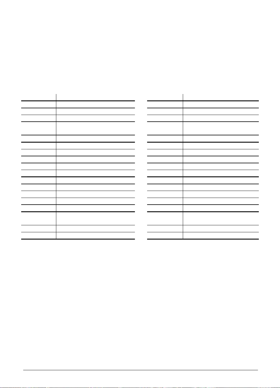
11.2 Connector assignment
Power supply see section "PLC power supply"
11.2.1 PLC inputs
The PLC inputs I0 to I31 are on connector X42 (PLC input).
The PLC inputs I128 to I152 are on the connector for the machine control panel (X46).
See also the heading "Machine control panel".
X42 PLC input D-sub 37-pin female connection
Pin number Assignment Pin number Assignment
1 I0 19 I18
2 I1 20 I19
3 I2 21 I20
4 I3 Acknowledgment for
"Control is operational" test
5 I4 23 I22
6 I5 24 I23
7 I6 25 I24
8 I7 26 I25
9 I8 27 I26
10 I9 28 I27
11 I10 29 I28
12 I11 30 I29
13 I12 31 I30
14 I13 32 I31
15 I14 33, 34 Do not use
16 I15 35, 36, 37 0 V (PLC) test output; Do not
17 I16 Housing Outer screen
18 I17
22 I21
use
3-54 TNC 407/TNC 415/TNC 425 11 PLC inputs/outputs 01.98
Page 85

11.2.2 PLC output
The PLC outputs O0 to O30 and the "Control operational" output are on connector X41 (PLC output).
The PLC outputs O0 to O7 are also to be found on the connector for the machine control panel
(X46). See also under heading "Machine control panel".
X41 PLC output
D-sub 37-pin female connection
Pin number Assignment Pin number Assignment
1 O0 19 O18
2 O1 20 O19
3 O2 21 O20
4 O3 22 O21
5 O4 23 O22
6 O5 24 O23
7 O6 25 O24
8 O7 26 O25
9 O8 27 O26
10 O9 28 O27
11 O10 29 O28
12 O11 30 O29
13 O12 31 O30
14 O13 32 Do not use
15 O14 33 0 V (PLC) test output;
16 O15 34 Control is operational
17 O16 35, 36, 37 24 V (PLC) test output;
18 O17 Housing Outer screen
1)
Not switched off by EMERGENCY STOP
1)
1)
1)
1)
1)
1)
1)
do not use
1)
do not use
11.2.3 PL connection
X47 PLC I/O Board
D-sub 37-pin male connection
Pin number Assignment Pin number Assignment
1, 2, 3 0 V 13 Screen
4 Serial IN 2 14, 15, 16 + 12 V (from PL)
5, 6, 17, 18 Do not use 19 Serial IN 1
7
8
RESET
WRITE EXTERN
9 WRITE EXTERN 22 Serial OUT
10
11
12
A5
A3
A1
01.98 TNC 407/TNC 415/TNC 425 11 PLC inputs/outputs 3-55
20 EMERGENCY STOP
21
23
24
25
Serial OUT
A4
A2
A0
Page 86
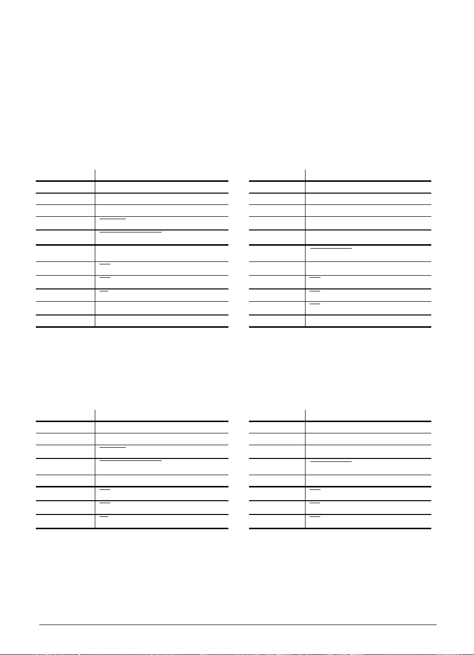
11.3 Connector assignment on the PL
Power supply see section "PLC power supply"
11.3.1 Connection to LE or PL #1
X1 to PL 410 / PL 410 B
X10 to PL 400
D-sub 25-pin female connector
Pin number Assignment Pin number Assignment
1, 2, 3 0 V 13 Screen
4 Serial IN 2 14, 15 + 12 V (from PL)
5, 6, 17, 18 Do not use 16 PL identification
7
8
9 WRITE EXTERN 21
10
11
12
RESET
WRITE EXTERN
A5
A3
A1
19 Serial IN 1
20 EMERGENCY STOP
Serial OUT
22 Serial OUT
23
24
25
Housing External shield
A4
A2
A0
11.3.2 Connection of PL #2
X2 at the PL 410 / PL 410 B D-sub 25-pin male connector
X11 at the PL 400 D-sub 25-pin female connector
Pin number Assignment Pin number Assignment
1, 2, 3 0 V 13 Screen
4-6, 14-18 Do not use 19 Serial IN 1
7
8
9 WRITE EXTERN 22 Serial OUT
10
11
12
3-56 TNC 407/TNC 415/TNC 425 11 PLC inputs/outputs 01.98
RESET
WRITE EXTERN
A5
A3
A1
20 EMERGENCY STOP
21
23
24
25
Serial OUT
A4
A2
A0
Page 87

11.3.3 PLC inputs/outputs on the PL 400
The PLC inputs/outputs on the PL 400 are spread over nine connectors assigned as follows:
Cables with a core cross-section ≥ dia. 0.14 mm² Cu must be used to connect the PLC inputs and
outputs. Maximum cable length 20 m.
X1 X2
Pin number Assignment Assignment Pin number Assignment Assignment
PL 400 #1 PL 400 #2 PL 400 #1 PL 400 #2
1 O32 O64 1 O43 O75
2 O33 O65 2 O44 O76
3 O34 O66 3 O45 O77
4 O35 O67 4 O46 O78
5 O36 O68 5 O47 O79
6 O37 O69 6 O48 O80
7 O38 O70 7 O49 O81
8 O39 O71 8 O50 O82
9 O40 O72 9 O51 O83
10 O41 O73 10 O52 O84
11 O42 O74 11 O53 O85
12 Do not use 12 Do not use
X3 X4
Pin number Assignment Assignment Pin number Assignment Assignment
PL 400 #1 PL 400 #2 PL 400 #1 PL 400 #2
1 O54 O86 1 I126 I254
2 O55 O87 2 I74 I202
3 O56
4 O57
5 O58
6 O59
7 O60
8 O61
9 O62
2)
2)
2)
2)
2)
2)
2)
O88
O89
O90
O91
O92
O93
O94
2)
2)
2)
2)
2)
2)
2)
3 I73 I201
4 I72 I200
5 I71 I199
6 I70 I198
7 I69 I197
8 I68 I196
9 I67 I195
10 Control ready 10 I66 I194
11 Do not use 11 I65 I193
12 +24 V not interruptible by
ext. EMERGENCY STOP
1)
+24V must always be connected even if the non-interruptible outputs are not used.
2)
Outputs not interruptible by ext. EMERGENCY STOP
1)
12 I64 I192
01.98 TNC 407/TNC 415/TNC 425 11 PLC inputs/outputs 3-57
Page 88

X5 X6
Pin number Assignment Assignment Pin number Assignment Assignment
PL 400 #1 PL 400 #2 PL 400 #1 PL 400 #2
1 I86 I214 1 I98 I226
2 I85 I213 2 I97 I225
3 I84 I212 3 I96 I224
4 I83 I211 4 I95 I223
5 I82 I210 5 I94 I222
6 I81 I209 6 I93 I221
7 I80 I208 7 I92 I220
8 I79 I207 8 I91 I219
9 I78 I206 9 I90 I218
10 I77 I205 10 I89 I217
11 I76 I204 11 I88 I216
12 I75 I203 12 I87 I215
X7 X8
Pin number Assignment Assignment Pin number Assignment Assignment
PL 400 #1 PL 400 #2 PL 400 #1 PL 400 #2
1 I110 I238 1 I122 I250
2 I109 I237 2 I121 I249
3 I108 I236 3 I120 I248
4 I107 I235 4 I119 I247
5 I106 I234 5 I118 I246
6 I105 I233 6 I117 I245
7 I104 I232 7 I116 I244
8 I103 I231 8 I115 I243
9 I102 I230 9 I114 I242
10 I101 I229 10 I113 I241
11 I100 I228 11 I112 I240
12 I99 I227 12 I111 I239
X9
Pin number Assignment Assignment
PL 400 #1 PL 400 #2
1 Do not use
2 Do not use
3 Do not use
4 I125 I253
5 I124 I252
6 I123 I251
3-58 TNC 407/TNC 415/TNC 425 11 PLC inputs/outputs 01.98
Page 89

11.3.4 PLC inputs/outputs on the PL 410 / PL 410 B
X3 Assignment X4 Assignment
Pin number PL 410 B #1 PL 410 B #2 Pin number PL 410 B #1 PL 410 B #2
PL 410 #1 PL 410 #2 PL 410 #1 PL 410 #2
1 I64 I192 1 I80 I208
2 I65 I193 2 I81 I209
3 I66 I194 3 I82 I210
4 I67 I195 4 I83 I211
5 I68 I196 5 I84 I212
6 I69 I197 6 I85 I213
7 I70 I198 7 I86 I214
8 I71 I199 8 I87 I215
9 I72 I200 9 I88 I216
10 I73 I201 10 I89 I217
11 I74 I202 11 I90 I218
12 I75 I203 12 I91 I219
13 I76 I204 13 I92 I220
14 I77 I205 14 I93 I221
15 I78 I206 15 I94 I222
16 I79 I207 16 I95 I223
X5 Assignment X6 Assignment
Pin number PL 410 B #1 PL 410 B #2 Pin number PL 410 B #1 PL 410 B #2
PL 410 #1 PL 410 #2 PL 410 #1 PL 410 #2
1 I96 I224 1 I112 I240
2 I97 I225 2 I113 I241
3 I98 I226 3 I114 I242
4 I99 I227 4 I115 I243
5 I100 I228 5 I116 I244
6 I101 I229 6 I117 I245
7 I102 I230 7 I118 I246
8 I103 I231 8 I119 I247
9 I104 I232 9 I120
10 I105 I233 10 I121
11 I106 I234 11 I122
12 I107 I235 12 I123
13 I108 I236 13 I124
14 I109 I237 14 I125
15 I110 I238 15 I126
16 I111 I239 16 I127
1)
1)
1)
1)
1)
1)
1)
1)
I248
I249
I250
I251
I252
I253
I254
I255
1)
1)
1)
1)
1)
1)
1)
1)
1)
These PLC inputs are not available when analogue inputs are active.
01.98 TNC 407/TNC 415/TNC 425 11 PLC inputs/outputs 3-59
Page 90
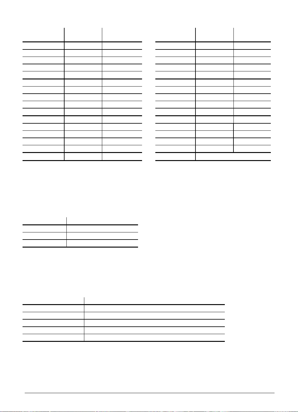
X7 Assignment X8 Assignment
Pin number PL 410 B #1 PL 410 B #2 Pin number PL 410 B #1 PL 410 B #2
PL 410 #1 PL 410 #2 PL 410 #1 PL 410 #2
1 O32 O64 1 O48 O80
2 O33 O65 2 O49 O81
3 O34 O66 3 O50 O82
4 O35 O67 4 O51 O83
5 O36 O68 5 O52 O84
6 O37 O69 6 O53 O85
7 O38 O70 7 O54 O86
8 O39 O71 8 O55 O87
9 O40 O72 9 O56 O88
10 O41 O73 10 O57 O89
11 O42 O74 11 O58 O90
12 O43 O75 12 O59 O91
13 O44 O76 13 O60 O92
14 O45 O77 14 O61
15 O46 O78 15 O62
1)
1)
O93
O94
1)
1)
16 O47 O79 16 Control ready
1)
These PLC outputs are not available when analogue inputs are active.
11.3.5 Analogue inputs on the PL 410 / PL 410 B
X15,X16,X17,X18 analogue input
Pin number Assignment
1 –10 V to +10 V
2 0 V (reference potential)
3 Screen
11.3.6 Inputs for thermistors on the PL 410 / PL 410 B
X19,X20,X21,X22 connection for Pt 100
Pin number Assignment
1 I + constant current for Pt 100 (5 mA)
2 U + measuring input for Pt 100
3 U - measuring input for Pt 100
4 I - constant current for Pt 100
5 Screen
3-60 TNC 407/TNC 415/TNC 425 11 PLC inputs/outputs 01.98
Page 91

11.4 Connector assignment on the PA 110
Power supply see section "PLC power supply"
X2,X3,X4,X5 analogue inputs
Assignment as X15,X16,X17,X18 on PL 410
X7,X8,X9,X10 connection for Pt 100
Assignment as X19,X20,X21,X22 on PL 410
11.5 Connecting cable
Please use only HEIDENHAIN connecting cables.
11.5.1 Connection of PLC inputs/outputs on the LE
HEIDENHAIN recommends the installation of a transfer unit with a terminal strip in the switch
cabinet.
max. 40 m
Id.-Nr. 263 954 ..
If a transfer unit is not required, use HEIDENHAIN connecting cable Id.-Nr. 244 005 ..
Assignment:
1 =green/red 14 = green/blue 27 = yellow/black
2 =brown/black 15 =yellow 28 = white/yellow
3 =white/black 16 = red 29 = grey/blue
4 =green/black 17 = grey 30 = pink/blue
5 =brown/red 18 = blue 31 = pink/red
6 =white/red 19 =pink 32 = brown/blue
7 =white/green 20 = white/grey 33 = pink/green
8 =red/blue 21 = yellow/grey 34 = brown
9 =yellow/red 22 =green/red 35 = yellow/pink
10 =grey/pink 23 = white/pink 36 = violet
11 =black 24 = grey/green 37 = white
12 =pink/brown 25 = yellow/brown
13 =yellow/blue 26 =grey/brown
If the connector is to be mounted at the customer's facility, HEIDENHAIN can provide a 37-pin
solderable connector (Id.-Nr. 243 937 ZY).
max. 25 m
Id.-Nr. 244 005..
01.98 TNC 407/TNC 415/TNC 425 11 PLC inputs/outputs 3-61
Page 92
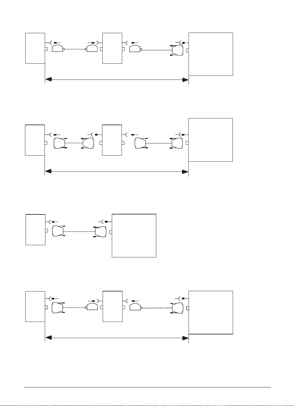
11.5.2 PL 400 connection
max. 3 m max. 20 m
PL 400 PL 400
Id.-Nr. 222 661.. Id.-Nr. 250 481..
X10X11X10
max. 20 m
11.5.3 PL 410 / PL 410 B connection
X1X2X1
PL 410 PL 410
Id.-Nr. 289 111 .. Id.-Nr. 289 111 ..
max. 20 m
11.5.4 PA 110 connection
max. 20 m
X1
X 47
LE
X47
max. 20 m
LE
PA 110
LE
Id.-Nr. 289 111 ..
max. 20 mmax. 3 m
X1
PA 110
Id.-Nr. 275 478 ..
3-62 TNC 407/TNC 415/TNC 425 11 PLC inputs/outputs 01.98
PL 400
X10X11
Id.-Nr. 250 481 ..
max. 20 m
X 47
LE
Page 93

11.5.5 Connection to analogue inputs
Connecting cable 2 x 0.14 mm² screened, 50 m max.
11.5.6 Connection to inputs for thermistors
The Pt 100 thermistors must be connected in four-wire mode.
I+
→
Measuring input U+
Measuring input U–
I–
→
1
2
3
4
5
Pt100 Customer´s cable
4 x 0.14 mm
2
screened, max 50 m
01.98 TNC 407/TNC 415/TNC 425 11 PLC inputs/outputs 3-63
Page 94

3
12 Machine operating panel
A separate 37-pin female connector (X46) is mounted on the logic unit for the connection to the
machine operating panel. This connector includes the PLC inputs I128 to I152, the PLC outputs
O0 to O7, as well as the 0 V and +24 V of the PLC power supply. The PLC inputs I128 to I152 may
be connected only with the power supply from pins 36 and 37, since this power supply is internally
secured as required.
HEIDENHAIN now offers a machine operating panel. It is installed beneath the TNC keyboard. The
dimension drawings show the standard set of keys. Four additional black keys are supplied with the
panel. The machine tool builder to use them replace unneeded axis keys, for example. Keys with
other symbols are also available upon request.
MB 410 Id.-Nr. 293 757 02 (suited to BC 110 and TE 400 black)
MB 420 Id.-Nr. 293 757 12 (suited to BC 120 and TE 400 B gray)
Assignment of PLC inputs to the keys of the MB:
I
136
128
129
I
I
I
I
135
148
130
I
I
134
137
I
I
I
133
149
I
I
I
131
132
138
139
140
I
I
I
143
145
I
I
144
141
I
I
150
I
I
142
146
147
I
01.98 TNC 407/TNC 415/TNC 425 12 Machine operating panel 3-65
Page 95

12.1 Pin connections
X46 Machine operating panel
Flange socket with female connector insert (37-pin)
Pin number Assignment Key on MB 410
1 I128 X–
2 I129 Y–
3 I130 Z–
4 I131 IV–
5 I132 V–
6 I133 X+
7 I134 Y+
8 I135 Z+
9 I136 IV+
10 I137 V+
11 I138 FN1
12 I139 FN2
13 I140 FN3
14 I141 FN4
15 I142 FN5
16 I143 Spindle on
17 I144 Spindle off
18 I145 Coolant on/off
19 I146 NC start
20 I147 NC stop
21 I148 Rapid traverse
22 I149 Black
23 I150 Black
24 I151
25 I152
26 O0
27 O1
28 O2
29 O3
30 O4
31 O5
32 O6
33 O7
34, 35 0 V (PLC)
36, 37 + 24 V (PLC)
Housing External shield
1)
2)
The PLC inputs I128 to I152 must be supplied with power only from pins 36 and 37, since this
power supply is properly safeguarded.
1)
Externally available PLC reference potential for the outputs O0-O7
2)
Externally available (via fuse) PLC supply voltage for the inputs.
3-66 TNC 407/TNC 415/TNC 425 12 Machine operating panel 01.98
Page 96

12.2 Connecting cable
Please use only HEIDENHAIN connecting cables.
HEIDENHAIN recommends that a 37-pin D-subminiature connector should be mounted on the
machine operating panel. The machine operating panel can be connected to the logic unit with the
standard HEIDENHAIN connecting cable Id.-Nr. 263 954 ..
max. 40 m
Id.-Nr. 263 954 ..
If the machine operating panel does not have a 37-pin D-subminiature connector, the HEIDENHAIN
connecting cable Id.-Nr. 244 005 .. may be used.
max. 40 m
Id.-Nr. 244 005 ..
For the assignments of the multi-core conductors see "PLC inputs/outputs".
If for any reason the manufacturers of the machine have to produce their own cable, a 37-pin
connector is available from HEIDENHAIN (Id.-Nr. 243 937 ZY).
01.98 TNC 407/TNC 415/TNC 425 12 Machine operating panel 3-67
Page 97

13 TNC keyboard
The TNC keyboard TE 400 is connected to the logic unit by a connecting cable. Additionally, the Soft
keys for the VDU (BC 110) are connected to the TNC keyboard by a flat cable. The flat cable is one
of the items supplied with the VDU.
13.1 Pin connections
On the logic unit
X45 TNC keyboard (TE 400)
D-sub female connector (37-pin)
Pin Number Assignment
1 RL0
2 RL1
3 RL2
4 RL3
5 RL4
6 RL5
7 RL6
8 RL7
9 RL8
10 RL9
11 RL10
12 RL11
13 RL12
14 RL13
15 RL14
16 RL15
17 RL16
18 RL17
19 RL18
20 SL0
21 SL1
22 SL2
23 SL3
24 SL4
25 SL5
26 SL6
27 SL7
28 RL19
29 RL20
30 Do not use
31 RL21
32 RL22
33 RL23
34 Spindle override (wiper)
35 Feed override (wiper)
36 + 5 V override-potentiometer
37 0 V override-potentiometer
Housing External screen
3-68 TNC 407/TNC 415/TNC 425 13 TNC keyboard 01.98
Page 98
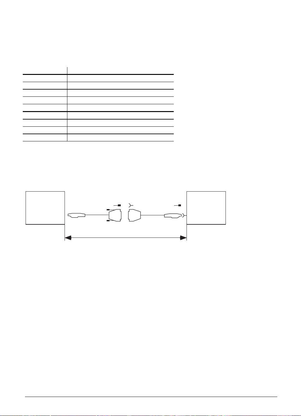
On the TNC keyboard
X2 for the connection to the logic unit
Pin connections as for X45 on the logic unit
X1 for the connection to the soft keys on the Visual Display Unit (BC)
Pin Number Assignment
1 SL0
2 SL1
3 SL2
4 SL3
5 Do not use
6 RL15
7 RL14
8 RL13
9 RL12
13.2 Connecting cable
Please use only HEIDENHAIN connecting cables.
Standardkabel
Id.-Nr. 263 954 ..
TE 400
The flat cable between the TNC keyboard and the VDU is included in the
package delivered with the VDU.
Verlängerungskabel
Id.-Nr. 263 955 ..
max. 40 m
LE
01.98 TNC 407/TNC 415/TNC 425 13 TNC keyboard 3-69
Page 99

14 VDU
The power supply for the VDU-BC 110 B is described under the heading "Power supply". The video
signals are transmitted via a connecting cable from the logic unit to the display unit. The soft keys
for the VDU are connected to the TNC keyboard by a flat cable. This flat cable is one of the items
supplied with the VDU.
14.1 Pin connections
X43 VDU (BC 110)
D-sub female connector (15-pin)
Pin Number Assignment
1, 8, 11 GND
2 to 6, 12, 13 Do not use
7R
9 V SYNC
10 H SYNC
14 G
15 B
Housing External shield
14.2 Connecting cable
Please use only HEIDENHAIN connecting cables.
Standardkabel
Id.-Nr. 250 477..
BC 110
max. 40 m
The flat connecting cable between the VDU and the TNC keyboard is one of the items supplied with
the VDU.
Verlängerungskabel
Id.-Nr. 254 640
LE
3-70 TNC 407/TNC 415/TNC 425 14 VDU 01.98
Page 100
14.3 Connecting the BC 120
X43 Visual Display Unit (BC 120)
Logic unit
I
D-sub connector
(female) 15-pin
2-row
1 GND 1 Coax I Red 1 1
2
3
4
5
6
7 R 7 Coax S Green 7 7
8 GND 8 Coax S Blue 8 8
9 VSYNC 9 9 9
10 HSYNC 10 Gray 10 10
11 GND 11 Green 11 11
12
13
14 G 14 Yellow 14 14
15 B 15 15 15
Housing External shield Housing Housing External shieldHousing Housing
Assignment 2-row / 3-row D-sub
Do not assign
Do not assign
Do not assign
Do not assign
Do not assign
Do not assign
Do not assign
Adapter
313 434 02
Extension cable
Id. Nr. 312 878 ..
D-sub connector
connector
(male) 15-pin
3-row
2 Coax I Green 2 2
3 Coax I Blue 3 3
444
555
6 Coax S Red 6 6
12 12 12
13 Pink 13 13
(female) 15-pin
3-row
BC 120
D-sub connector
(male) 15-pin
3-row
01.98 TNC 407/TNC 415/TNC 425 14 VDU 3-71
 Loading...