

Page 1
HEIDENHAIN
February 1994
User's Manual
ISO Programming
TNC 360
Page 2
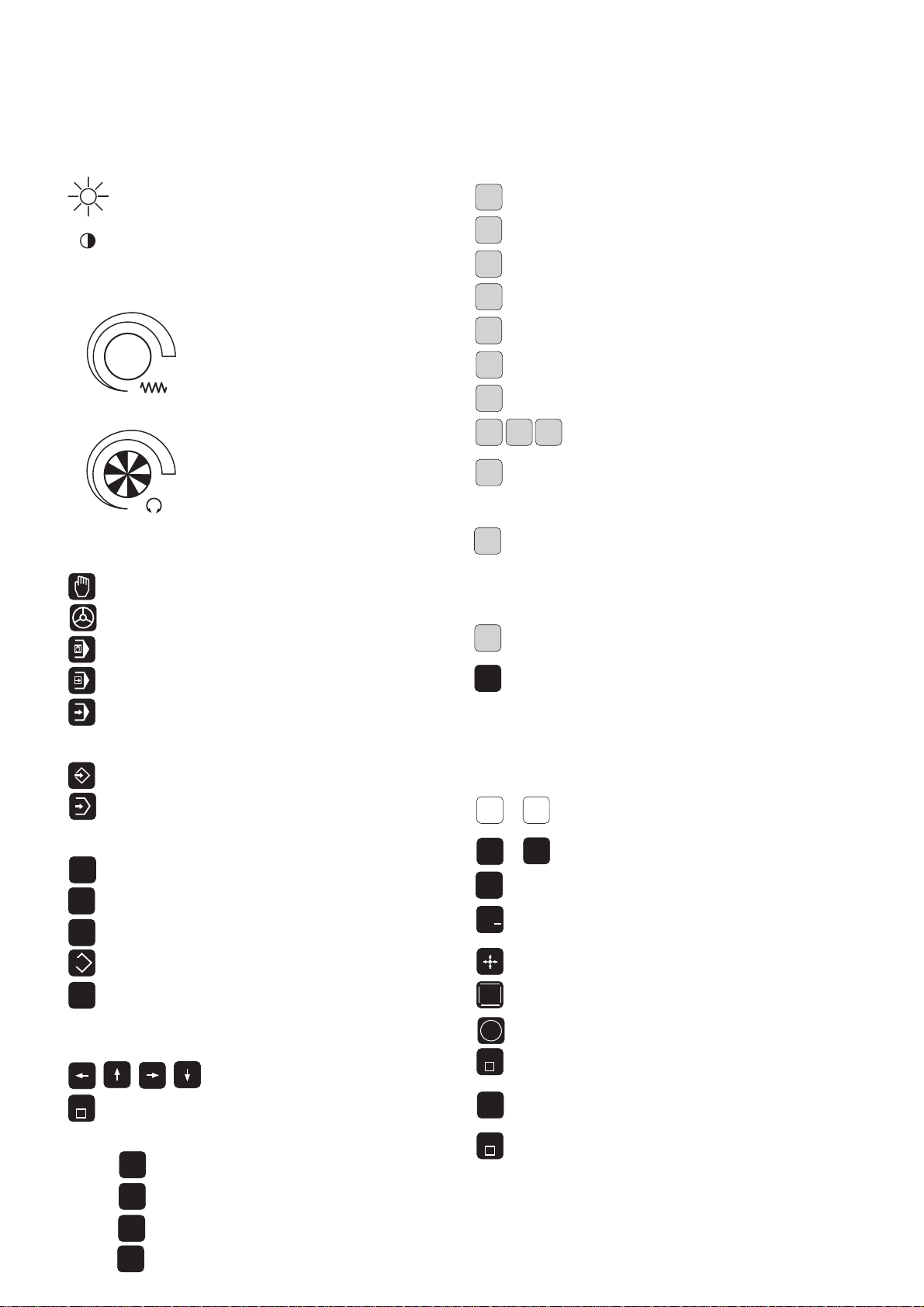
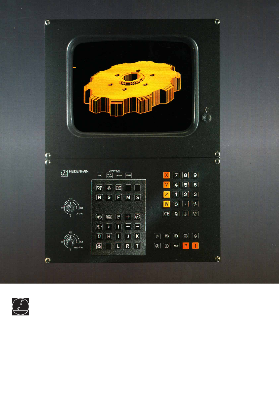
Keys and Controls on the TNC 360
N
M
D
HKJ
I
ENT
L
Controls on the Visual Display Unit
Brightness
Contrast
Override Knobs
100
50
0
100
50
0
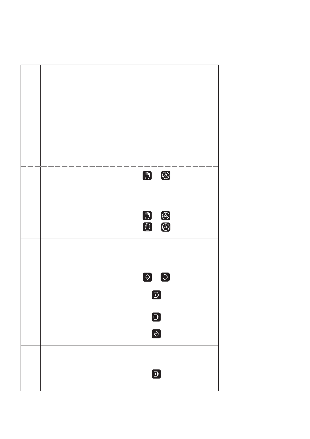
Machine Operating Modes
F %
S %
MANUAL OPERATION
ELECTRONIC HANDWHEEL
POSITIONING WITH MANUAL DATA INPUT
PROGRAM RUN, SINGLE BLOCK
1
50
1
50
Feed rate
Spindle speed
Address Letters for ISO Programming
Block number
G
F
S
R
T
TOUCH
PROBE
G function
Feed rate / Dwell time with G04 / Scaling factor
Miscellaneous function (M function)
Spindle speed in rpm
Parameter definition
Polar angle/Rotation angle in cycle G73
X, Y, Z coordinate of circle center/pole
Assign a label number with G98/
Jump to a label number/
Tool length with G99
Polar radius/
Rounding radius with G25, G26, G27
Chamfer with G24
Circle radius with G02, G03, G05
Tool radius with G99
Tool definition with G99/
Tool call
Set a datum with the 3D touch probe system
PROGRAM RUN, FULL SEQUENCE
Programming Modes
PROGRAMMING AND EDITING
TEST RUN
Program and File Management
PGM
NR
CL
PGM
PGM
CALL
EXT
MOD
Moving the Cursor and Selecting Blocks, Cycles
and Parameter Functions with GOTO
GOTO
Graphics
MOD
BLK
FORM
Select programs and files
Delete programs and files
Enter program call in a program
External data transfer
Supplementary modes
Move the cursor (highlight)
Go directly to blocks, cycles and
parameter functions
Graphic operating modes
Define blank form, reset blank form
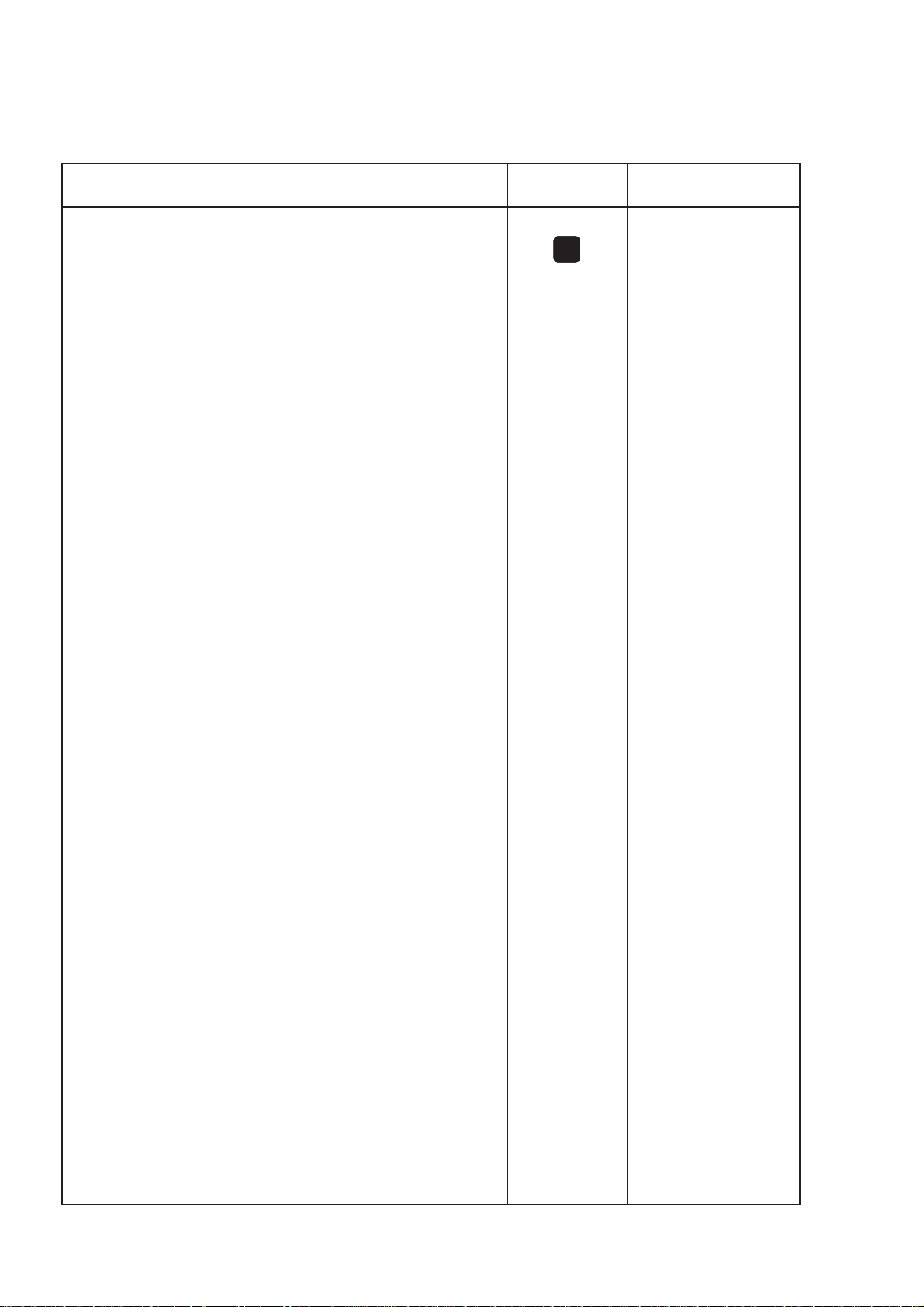
Entering Numbers and Coordinate Axes, Editing
X
0
+
NO
ENT
END
CE
DEL
...
...
.
/
Select or enter coordinate axes
IV
in a program
9
Numbers
Decimal point
Algebraic sign
Actual position capture
Ignore dialog queries, delete words
Confirm entry and resume dialog
Conclude block
Clear numerical entry
or TNC message
Abort dialog; delete program sections
MAGN
START
Magnify detail
Start graphic simulation
Page 3
TNC Guideline:
From workpiece drawing to
program-controlled machining
Step Task TNC Refer to
operating mode Section
Preparation
1 Select tools —— ——
2 Set workpiece datum
for coordinate system —— ——
3 Determine spindle speeds
and feed rates —— 11.4
4 Switch on machine —— 1.3
5 Traverse reference marks or 1.3, 2.1
6 Clamp workpiece —— ——
7 Set the datum /
Reset position display ...
7a ... with the 3D touch probe or 2.5
7b ... without the 3D touch probe or 2.3
Entering and testing part programs
8 Enter part program
or download
over external 5 to 8
data interface or or 10
9 Test part program for errors 3.1
10 Test run: Run program
block by block without tool 3.2
EXT
11 If necessary: Optimize
part program 5 to 8
Machining the workpiece
12 Insert tool and
run part program 3.2
Page 4
Sequence of Program Steps
Milling an outside contour
Programming step Key/Function Refer to Section
1 Create or select program 4.4
Input: Program number
Unit of measure for programming
2 Define workpiece blank for graphic display G30/G31 4.4
3 Define tool(s) G99 4.2
Input: Tool number T...
Tool length L...
Tool radius R...
4 Call tool data T... 4.2
Input: Tool number
Spindle axis G17
Spindle speed S...
5 Tool change
Input: Feed rate (rapid traverse) G00 e.g. 5.4
Radius compensation G40
Coordinates of the tool change position X... Y... Z...
Miscellaneous function (tool change) M06
6 Move to starting position 5.2/5.4
Input: Feed rate (rapid traverse) G00
Coordinates of the starting position X... Y...
Radius compensation G40
Miscellaneous function (spindle on, clockwise) M03
PGM
NR
7 Move tool to (first) working depth 5.4
Input: Feed rate (rapid traverse) G00
Coordinate of the (first) working depth Z...
8 Move to first contour point 5.2/5.4
Input: Linear interpolation G01
Radius compensation for machining G41/G42
Coordinates of the first contour point X... Y...
Machining feed rate F...
if desired, with smooth approach: program G26 after this block
9 Machining to last contour point 5 to 8
Input: Enter all necessary values for
each contour element
if desired, with smooth departure: program G27 after the last
radius-compensated block
10 Move to end position 5.2/5.4
Input: Feed rate (rapid traverse) G00
Cancel radius compensation G40
Coordinates of the end position X... Y...
Miscellaneous function (spindle stop) M05
11 Retract tool in spindle axis 5.2/5.4
Input: Feed rate (rapid traverse) G00
Coordinate above the workpiece Z...
Miscellaneous function (end of program) M02
12 End of program
Page 5

How to use this manual
This manual describes functions and features available on the TNC 360
from NC software number 259 900 08.
This manual describes all available TNC functions. However, since the
machine builder has modified (with machine parameters) the available
range of TNC functions to interface the control to his specific machine,
this manual may describe some functions which are not available on your
TNC.
TNC functions which are not available on every machine are, for example:
• Probing functions for the 3D touch probe system
• Rigid tapping
If in doubt, please contact the machine tool builder.
TNC programming courses are offered by many machine tool builders as
well as by HEIDENHAIN. We recommend these courses as an effective
way of improving your programming skill and sharing information and
ideas with other TNC users.
TNC 360
Page 6
The TNC beginner can use the manual as a workbook. The first part of
the manual deals with the basics of NC technology and describes the
TNC functions. It then introduces the techniques of conversational
programming. Each new function is thoroughly described when it is first
introduced, and the numerous examples can be tried out directly on the
TNC. The TNC beginner should work through this manual from beginning
to end to ensure that he is capable of fully exploiting the features of this
powerful tool.
For the TNC expert, this manual serves as a comprehensive reference
work. The table of contents and cross references enable him to quickly
find the topics and information he needs. Easy-to-read dialog flowcharts
show him how to enter the required data for each function.
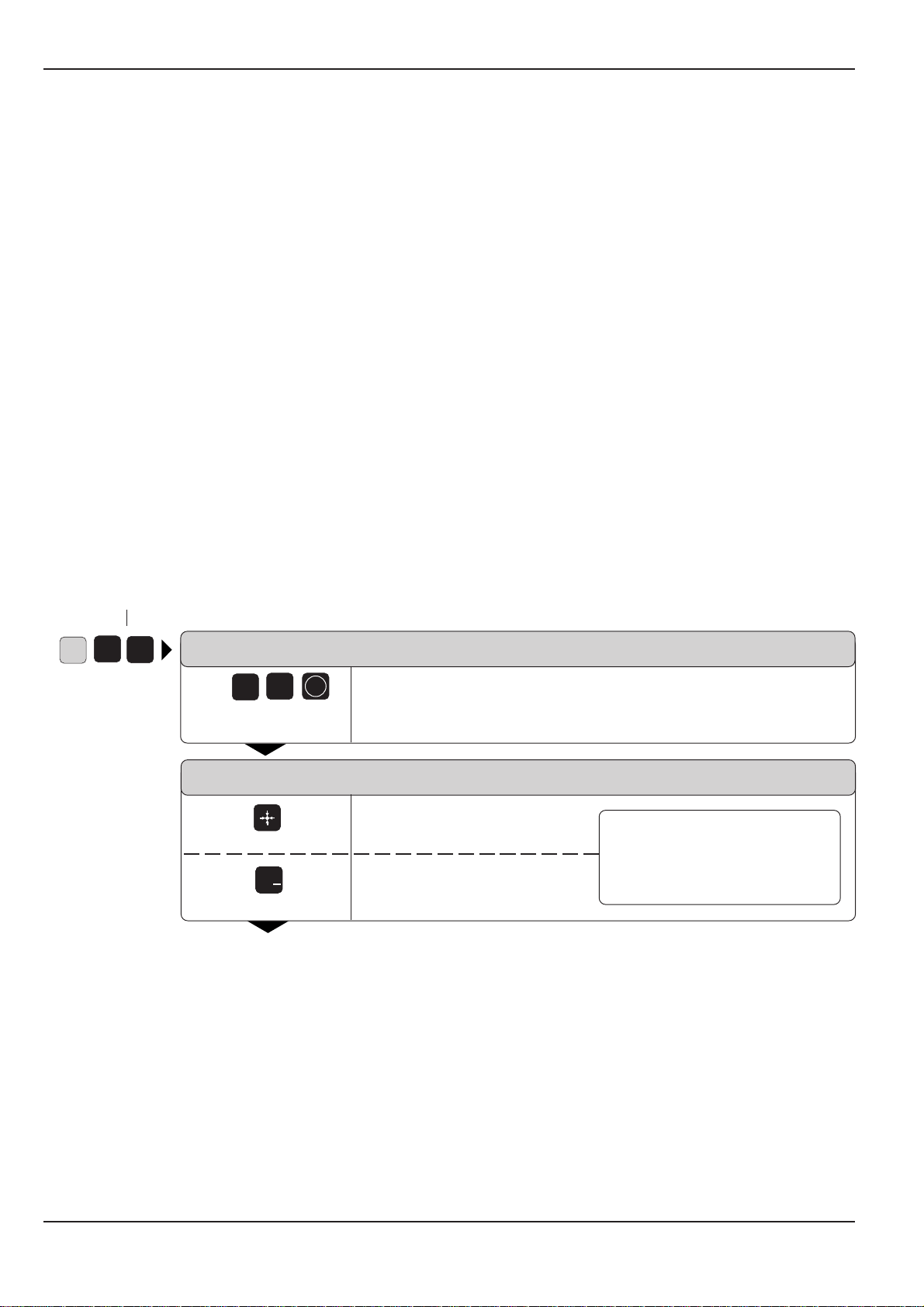
The dialog flow charts consist of sequentially arranged instruction boxes.
Each key is illustrated next to an explanation of its function to aid the
beginner when he is performing the operation for the first time. The
experienced user can use the key sequences illustrated in the left part of
the flowchart as a quick overview. The TNC dialogs in the instruction
boxes are always presented on a gray background.
G
Layout of the dialog flowcharts
Dialog initiation keys
3
8
DIALOG PROMPT (ON TNC SCREEN)
3
8
e.g.
Answer the prompt with
these keys
NEXT DIALOG QUESTION
Press this key
+
/
Or press this key
.
.
.
ENT
The functions of the keys are explained here.
Function of the key.
A dashed line means that either
the key above or below it can be
Function of an alternative key.
The trail of dots indicates that:
• the dialog is not fully shown, or
• the dialog continues on the next page.
pressed.
TNC 360
Page 7

Contents User's Manual TNC 360
ISO Programming
Introduction
Manual Operation and Setup
Test Run and Program Run
Programming
Programming Tool Movements
Subprograms and Program Section Repeats
Programming with Q Parameters
Cycles
External Data Transfer
MOD-Functions
Tabels, Overviews and Diagrams
1
2
3
4
5
6
7
8
9
10
11
Page 8

1 Introduction
1.1 The TNC 360 .......................................................................................... 1-2
The Operating Panel .................................................................................................... 1-3
The Screen .................................................................................................................. 1-3
TNC Accessories ......................................................................................................... 1-5
1.2 Fundamentals of Numerical Control (NC).......................................... 1-6
Introduction ................................................................................................................. 1-6
What is NC? ................................................................................................................ 1-6
The part program ......................................................................................................... 1-6
Programming ............................................................................................................... 1-6
Reference system ....................................................................................................... 1-7
Cartesian coordinate system ....................................................................................... 1-7
Additional axes ............................................................................................................ 1-8
Polar coordinates ......................................................................................................... 1-8
Setting the pole ........................................................................................................... 1-9
Setting the datum ........................................................................................................ 1-9
Absolute workpiece positions ................................................................................... 1-11
Incremental workpiece positions .............................................................................. 1-11
Programming tool movements.................................................................................. 1-13
Position encoders ...................................................................................................... 1-13
Reference marks ...................................................................................................... 1-13
1.3 Switch-On ........................................................................................... 1-14
1.4 Graphics and Status Display ............................................................. 1-15
Plan view ................................................................................................................... 1-15
Projection in three planes .......................................................................................... 1-16
3D view .................................................................................................................... 1-16
Status display ............................................................................................................ 1-18
1.5 Programs ............................................................................................. 1-19
Program directory ...................................................................................................... 1-19
Selecting, erasing and protecting programs .............................................................. 1-20
TNC 360
Page 9

2 Manual Operation and Setup
2.1 Moving the Machine Axes ................................................................... 2-2
Traversing with the machine axis direction buttons .................................................... 2-2
Traversing with the electronic handwheel .................................................................. 2-3
Working with the HR 330 Electronic Handwheel ........................................................ 2-3
Incremental jog positioning ......................................................................................... 2-4
Positioning with manual data input (MDI) ................................................................... 2-4
2.2 Spindle Speed S, Feed Rate F and Miscellaneous Function M ........ 2-5
To enter the spindle speed S ...................................................................................... 2-5
To enter the miscellaneous function M....................................................................... 2-6
To change the spindle speed S ................................................................................... 2-6
To change the feed rate F ........................................................................................... 2-6
2.3 Setting the Datum without a 3D Touch Probe .................................. 2-7
Setting the datum in the tool axis ............................................................................... 2-7
Setting the datum in the working plane ...................................................................... 2-8
2.4 3D Touch Probe System ...................................................................... 2-9
3D Touch probe applications ....................................................................................... 2-9
Selecting the touch probe menu ................................................................................. 2-9
Calibrating the 3D touch probe.................................................................................. 2-10
Compensating workpiece misalignment ................................................................... 2-12
2.5 Setting the Datum with the 3D Touch Probe System .................... 2-14
Setting the datum in a specific axis .......................................................................... 2-14
Corner as datum ........................................................................................................ 2-15
Circle center as datum .............................................................................................. 2-17
2.6 Measuring with the 3D Touch Probe System .................................. 2-19
Finding the coordinate of a position on an aligned workpiece .................................. 2-19
Finding the coordinates of a corner in the working plane ......................................... 2-19
Measuring workpiece dimensions ............................................................................ 2-20
Measuring angles ...................................................................................................... 2-21
TNC 360
Page 10

3 Test Run and Program Run
3.1 Test Run ................................................................................................ 3-2
To do a test run ........................................................................................................... 3-2
3.2 Program Run ......................................................................................... 3-3
To run a part program .................................................................................................. 3-3
Interrupting machining ................................................................................................ 3-4
Resuming program run after an interruption ............................................................... 3-5
3.3 Blockwise Transfer: Executing Long Programs ................................. 3-6
Jumping over blocks ................................................................................................... 3-7
TNC 360
Page 11

4 Programming
4.1 Editing Part Programs .......................................................................... 4-2
Layout of a program .................................................................................................... 4-2
Editing functions.......................................................................................................... 4-3
4.2 Tools ...................................................................................................... 4-5
Determining tool data .................................................................................................. 4-5
Entering tool data into the program............................................................................. 4-7
Entering tool data in program 0 ................................................................................... 4-8
Calling tool data ........................................................................................................... 4-9
Tool change ................................................................................................................. 4-9
4.3 Tool Compensation Values ............................................................... 4-11
Effect of tool compensation values ........................................................................... 4-11
Tool radius compensation ......................................................................................... 4-11
Machining corners ..................................................................................................... 4-13
4.4 Program Creation ............................................................................... 4-14
To create a new part program ................................................................................... 4-14
Defining the blank form ............................................................................................. 4-14
4.5 Entering Tool-Related Data ............................................................... 4-17
Feed rate F ................................................................................................................ 4-17
Spindle speed S ......................................................................................................... 4-18
4.6 Entering Miscellaneous Functions and STOP .................................. 4-19
4.7 Actual Position Capture ..................................................................... 4-20
TNC 360
Page 12

5 Programming Tool Movements
5.1 General Information on Programming Tool Movements ................. 5-2
5.2 Contour Approach and Departure ...................................................... 5-4
Starting and end positions ........................................................................................... 5-4
Smooth approach and departure ................................................................................. 5-6
5.3 Path Functions ...................................................................................... 5-7
General information ..................................................................................................... 5-7
Machine axis movement under program control ........................................................ 5-7
Overview of path functions ......................................................................................... 5-9
5.4 Path Contours - Cartesian Coordinates ............................................ 5-10
Straight line at rapid traverse G00 ............................................................................. 5-10
Straight line with feed rate G01 F ... ......................................................................... 5-10
Chamfer G24 ............................................................................................................. 5-13
Circles and circular arcs - General information .......................................................... 5-15
Circle center I, J, K ................................................................................................... 5-16
Circular path G02/G03/G05 around the circle center I, J, K ...................................... 5-18
Circular path G02/G03/G05 with defined radius ........................................................ 5-21
Circular path G06 with tangential connection............................................................ 5-24
Corner rounding G25 ................................................................................................. 5-26
5.5 Path Contours - Polar Coordinates ................................................... 5-28
Polar coordinate origin: Pole I, J, K ........................................................................... 5-28
Straight line at rapid traverse G10 ............................................................................. 5-28
Straight line with feed rate G11 F ... ......................................................................... 5-28
Circular path G12/G13/G15 around pole I, J, K .......................................................... 5-30
Circular path G16 with tangential connection............................................................ 5-32
Helical interpolation ................................................................................................... 5-33
5.6 M Functions for Contouring Behavior and Coordinate Data.......... 5-36
Smoothing corners: M90 ........................................................................................... 5-36
Machining small contour steps: M97 ........................................................................ 5-37
Machining open contours: M98 ................................................................................ 5-38
Programming machine-referenced coordinates: M91/M92 ...................................... 5-39
5.7 Positioning with Manual Data Input (MDI) ...................................... 5-41
TNC 360
Page 13

6 Subprograms and Program Section Repeats
6.1 Subprograms ........................................................................................ 6-2
Principle ...................................................................................................................... 6-2
Operating limits ........................................................................................................... 6-2
Programming and calling subprograms ....................................................................... 6-3
6.2 Program Section Repeats .................................................................... 6-5
Principle ...................................................................................................................... 6-5
Programming notes ..................................................................................................... 6-5
Programming and calling a program section repeat .................................................... 6-5
6.3 Main Program as Subprogram ............................................................ 6-8
Principle ...................................................................................................................... 6-8
Operating limits ........................................................................................................... 6-8
To call a main program as a subprogram .................................................................... 6-8
6.4 Nesting .................................................................................................. 6-9
Nesting depth .............................................................................................................. 6-9
Subprogram in a subprogram ...................................................................................... 6-9
Repeating program section repeats .......................................................................... 6-11
Repeating subprograms ............................................................................................ 6-12
TNC 360
Page 14

7 Programming with Q Parameters
7.1 Part Families — Q Parameters Instead of Numerical Values ........... 7-3
7.2 Describing Contours Through Mathematical Functions................... 7-5
Overview ..................................................................................................................... 7-5
7.3 Trigonometric Functions ..................................................................... 7-7
Overview ..................................................................................................................... 7-7
7.4 If-Then Operations with Q Parameters .............................................. 7-8
Jumps ...................................................................................................................... 7-8
Overview ..................................................................................................................... 7-8
7.5 Checking and Changing Q Parameters............................................. 7-10
7.6 Output of Q Parameters and Messages ........................................... 7-11
Displaying error messages ........................................................................................ 7-11
Output through an external data interface ................................................................ 7-11
Assigning values for the PLC .................................................................................... 7-11
7.7 Measuring with the 3D Touch Probe During Program Run............ 7-12
7.8 Examples for Exercise ........................................................................ 7-14
Rectangular pocket with corner rounding and tangential approach .......................... 7-14
Bolt hole circles ......................................................................................................... 7-15
Ellipse .................................................................................................................... 7-17
Machining a hemisphere with an end mill................................................................. 7-19
TNC 360
Page 15

8 Cycles
8.1 General Overview of Cycles ................................................................ 8-2
8.2 Simple Fixed Cycles.............................................................................. 8-4
8.3 SL Cycles ............................................................................................. 8-15
Programming a cycle ................................................................................................... 8-2
Dimensions in the tool axis ......................................................................................... 8-3
PECKING G83 .............................................................................................................. 8-4
TAPPING with floating tap holder G84 ........................................................................ 8-6
RIGID TAPPING G85 ................................................................................................... 8-8
SLOT MILLING G74 .................................................................................................... 8-9
POCKET MILLING G75/G76 ...................................................................................... 8-11
CIRCULAR POCKET MILLING G77/G78 ................................................................... 8-13
CONTOUR GEOMETRY G37 .................................................................................... 8-16
ROUGH-OUT G57 ..................................................................................................... 8-17
Overlapping contours ................................................................................................ 8-19
PILOT DRILLING G56................................................................................................ 8-25
CONTOUR MILLING G58/G59 .................................................................................. 8-26
8.4 Cycles for Coordinate Transformations ........................................... 8-29
DATUM SHIFT G54 ................................................................................................... 8-30
MIRROR IMAGE G28 ................................................................................................ 8-33
ROTATION G73 ......................................................................................................... 8-35
SCALING FACTOR G72 ............................................................................................. 8-36
8.5 Other Cycles ........................................................................................ 8-38
DWELL TIME G04 ..................................................................................................... 8-38
PROGRAM CALL G39 ............................................................................................... 8-38
ORIENTED SPINDLE STOP G36 ............................................................................... 8-39
TNC 360
Page 16

9 External Data Transfer
9.1 Menu for External Data Transfer......................................................... 9-2
Blockwise transfer....................................................................................................... 9-2
9.2 Pin Layout and Connecting Cable for Data Interfaces ...................... 9-3
RS-232-C/V.24 Interface .............................................................................................. 9-3
9.3 Preparing the Devices for Data Transfer ............................................ 9-4
HEIDENHAIN devices ................................................................................................. 9-4
Non-HEIDENHAIN devices ......................................................................................... 9-4
TNC 360
Page 17

10 MOD Functions
10.1 Selecting, Changing and Exiting the MOD Functions..................... 10-2
10.2 NC and PLC Software Numbers ........................................................ 10-2
10.3 Entering the Code Number................................................................ 10-3
10.4 Setting the External Data Interfaces ................................................ 10-3
BAUD RATE .............................................................................................................. 10-3
RS-232-C Interface .................................................................................................... 10-3
10.5 Machine-Specific User Parameters ................................................... 10-4
10.6 Selecting Position Display Types ...................................................... 10-4
10.7 Selecting the Unit of Measurement ................................................. 10-5
10.8 Selecting the Programming Language............................................. 10-5
10.9 Setting the Axis Traverse Limits ....................................................... 10-6
TNC 360
Page 18

11 Tables, Overviews, Diagrams
11.1 General User Parameters ................................................................... 11-2
Selecting the general user parameters ..................................................................... 11-2
Parameters for external data transfer ....................................................................... 11-2
Parameters for 3D touch probes ............................................................................... 11-4
Parameters for TNC displays and the editor ............................................................. 11-4
Parameters for machining and program run .............................................................. 11-7
Parameters for override behavior and electronic handwheel .................................... 11-9
11.2 Miscellaneous Functions (M Functions) ......................................... 11-11
Miscellaneous functions with predetermined effect............................................... 11-11
Vacant miscellaneous functions .............................................................................. 11-12
11.3 Preassigned Q Parameters .............................................................. 11-13
11.4 Diagrams for Machining .................................................................. 11-15
Spindle speed S ....................................................................................................... 11-15
Feed rate F .............................................................................................................. 11-16
Feed rate F for tapping ............................................................................................ 11-17
11.5 Features, Specifications and Accessories ...................................... 11-18
TNC 360 .................................................................................................................. 11-18
Accessories ............................................................................................................. 11-20
11.6 TNC Error Messages ......................................................................... 11-21
TNC error messages during programming .............................................................. 11-21
TNC error messages during test run and program run............................................ 11-22
11.7 Address letters (ISO programming) ............................................... 11-25
G Functions ............................................................................................................. 11-25
Other address letters .............................................................................................. 11-26
Parameter definitions .............................................................................................. 11-27
TNC 360
Page 19

1 Introduction
1.1 The TNC 360
Control
The TNC 360 is a shop-floor programmable contouring control for milling
machines, boring machines and machining centers with up to four axes.
The spindle can be rotated to a given angular stop position (oriented
spindle stop).
Visual display unit and operating panel
The monochrome screen clearly displays all information necessary for
operating the TNC. In addition to the CRT monitor (BE 212), the TNC 360
can also be used with a flat luminescent screen (BF 110). The keys on the
operating panel are grouped according to their functions. This
simplifies programming and the application of the TNC functions.
Programming
The TNC 360 is programmed in ISO format. Programming with the easy to
understand HEIDENHAIN plain language dialog format is also possible and
is described in the TNC 360 User's Manual for HEIDENHAIN Conversational Programming.
Graphics
The graphic simulation enables you to test programs before actual machining. Various types of graphic representation can be selected.
Compatibility
The TNC 360 can execute any part program that was programmed on a
TNC 150B HEIDENHAIN control or any subsequent version.
TNC 3601-2
Page 20
1 Introduction
1.1 The TNC 360
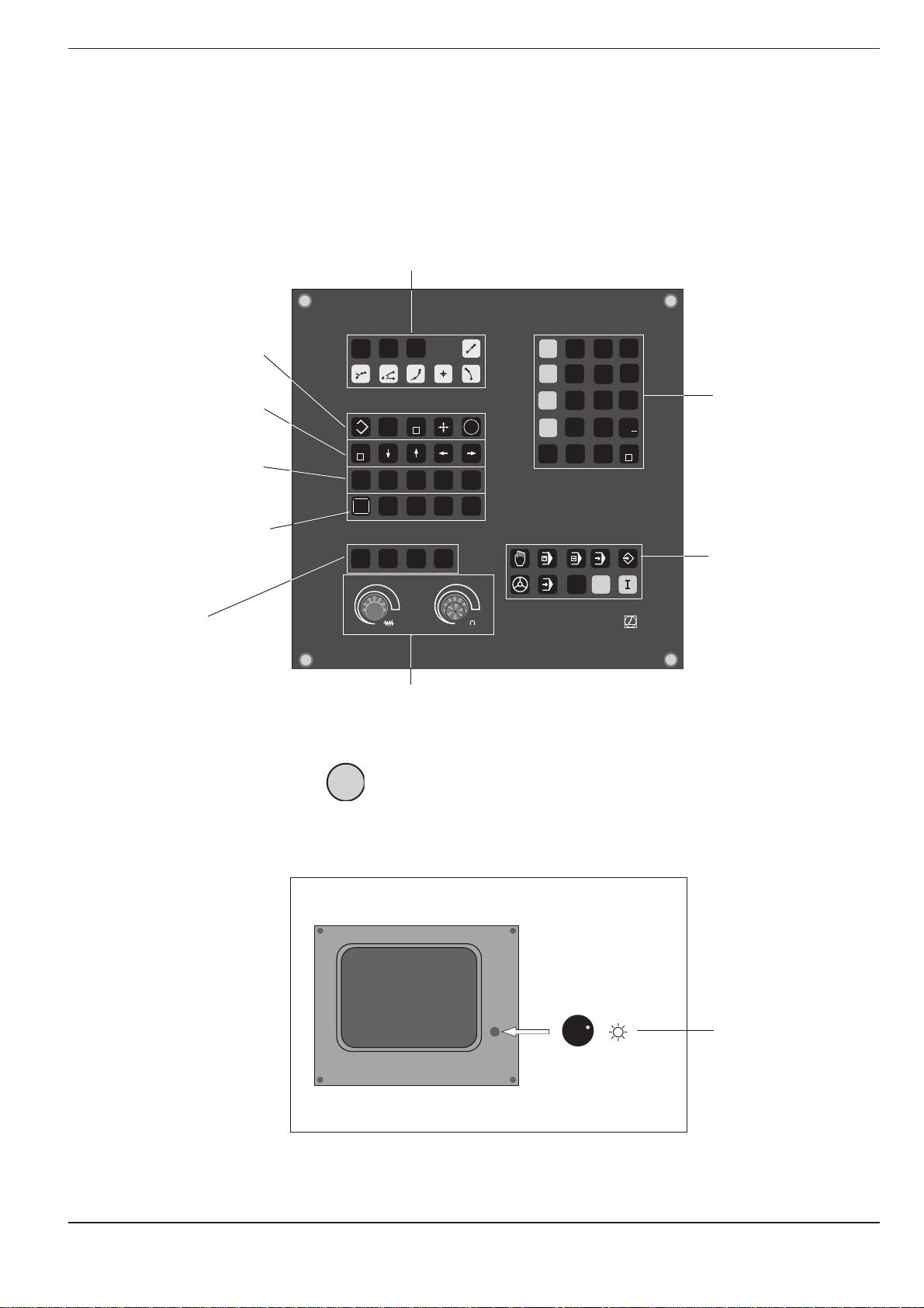
The Operating Panel
The keys on the TNC operating panel are grouped according to their
functions:
• Program selection
• Address letters
• External data transfer
• Probing functions
• Editing functions
• Jump instruction GOTO
• Arrow keys
• Address letters
• NO ENT key
• Tool-related address letters
Graphic operating
modes
PGM
NR
CR
EXT
GOTO
STOP
NO
ENT
MOD
50
PGM
CL
CALL
PGM
RND
CT
DEL
TOUCH
PROBE
CYCL
CYCL
CALL
DEF
TOOL
TOOL
CALL
DEF
GRAPHICS
BLK
MAGN START
FORM
100
150
F %
0
L
CC
C
ENT
LBL
LBL
CALL
SET
L
R
R
R
-
+
IV
CE
7 8
X
4
Y
1
Z
0
Q
5
2 3
.
Q
DEF
9
6
• Numerical entries
• Axis selection
+
/
END
Operating modes
100
50
150
S %
0
MOD
P
HEIDENHAIN
Override controls
for spindle speed
and feed rate
The functions of the individual keys are described on the inside front cover. An overview
of the address letters used for ISO programming is provided in Chapter 11.
The machine operating buttons, such as for NC start, are described in the manual for your machine tool.
I
In this manual they are shown in gray.
The Screen
Brightness control
(BE 212 only)
Header
The header of the screen shows the selected operating mode. Dialog
questions and TNC messages also appear there.
TNC 360 1-3
Page 21
1 Introduction
1.1 The TNC 360
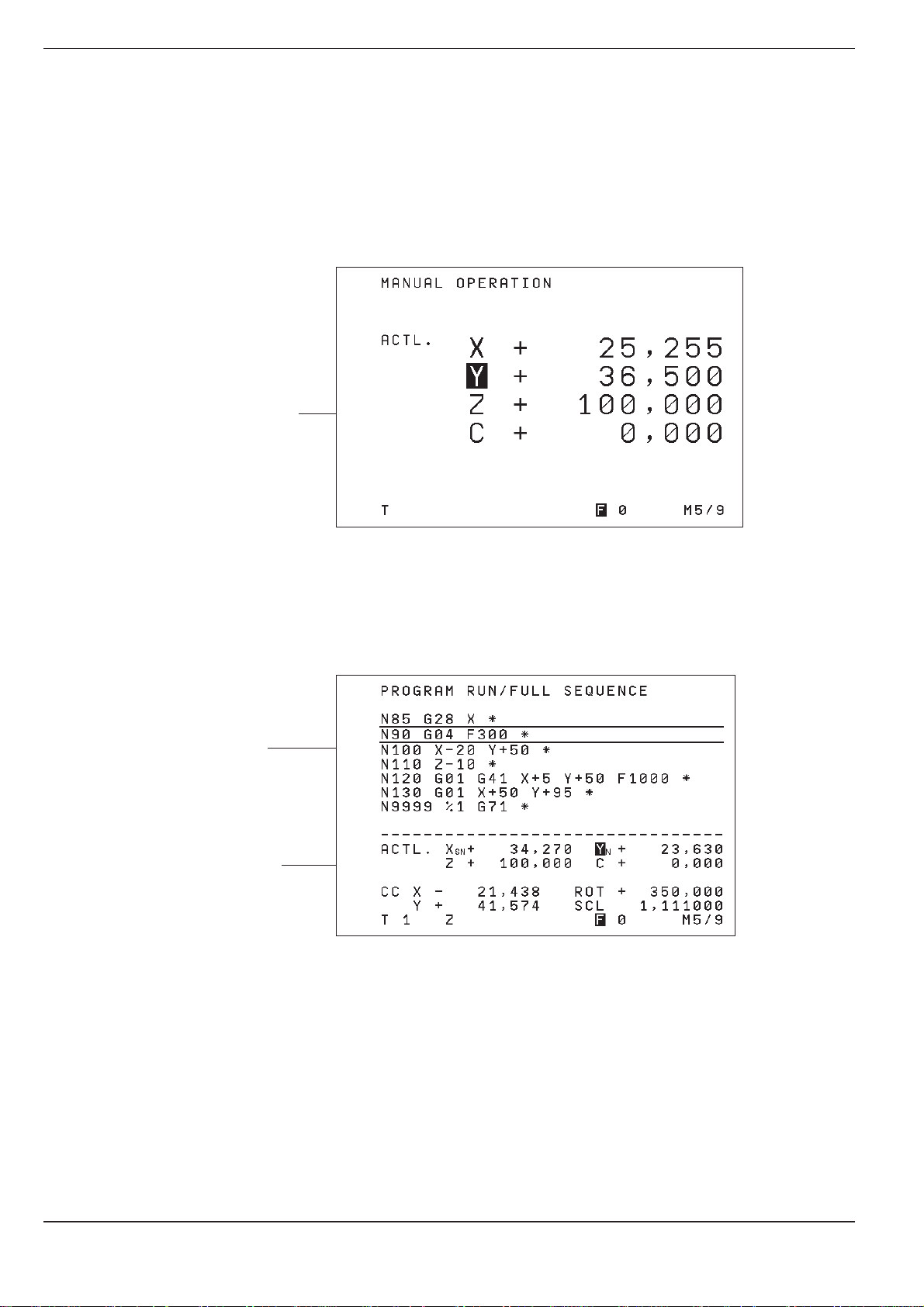
Screen Layout
MANUAL and EL. HANDWHEEL operating modes:
A machine operating mode has been selected
• Coordinates
• Selected axis
• ❊ means:
control is in
operation
• Status display,
e.g. feed rate F,
miscellaneous
function M
A program run operating mode has been selected
Section of
selected
program
Status display
The screen layout is the same in the operating modes PROGRAM RUN,
PROGRAMMING AND EDITING and TEST RUN. The current block is
shown between two horizontal lines.
TNC 3601-4
Page 22
1 Introduction
1.1 The TNC 360
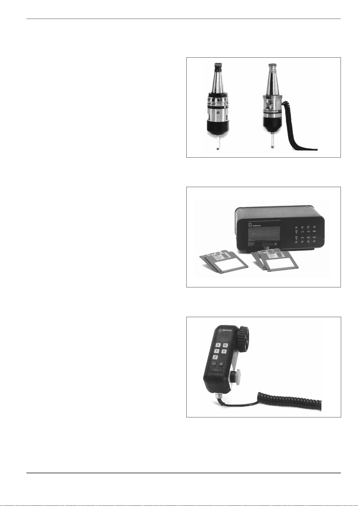
TNC Accessories
3D Touch Probe Systems
The TNC features the following functions for the
HEIDENHAIN 3D touch probe systems:
• Automatic workpiece alignment (compensation
of workpiece misalignment)
• Datum setting
• Measurements of the workpiece can be performed during program run
• Digitizing 3D forms (optional, only available with
HEIDENHAIN plain language dialog programming)
The TS 120 touch probe system is connected to the
control via cable, while the TS 510 communicates
by means of infrared light.
Fig. 1.5: HEIDENHAIN 3D Touch Probe Systems TS 120 and TS 511
Floppy Disk Unit
The HEIDENHAIN FE 401 floppy disk unit serves as
an external memory for the TNC, allowing you to
store your programs externally on diskette.
The FE 401 can also be used to transfer programs
that were written on a PC into the TNC. Extremely
long programs which exceed the TNC's memory
capacity are “drip fed” block by block. The machine
executes the transferred blocks and erases them
immediately, freeing memory for further blocks
from the FE.
Electronic Handwheels
Electronic handwheels provide precise manual
control of the axis slides. As on conventional
machines, turning the handwheel moves the axis
by a defined amount. The traverse distance per
revolution of the handwheel can be adjusted over a
wide range.
Fig. 1.6: HEIDENHAIN FE 401 Floppy Disk Unit
Portable handwheels, such as the HR 330, are
connected to the TNC by cable. Built-in handwheels, such as the HR 130, are built into the
machine operating panel.
An adapter allows up to three handwheels to be
connected simultaneously. Your machine tool
builder can tell you more about the handwheel
configuration of your machine.
Fig. 1.7: The HR 330 Electronic Handwheel
TNC 360 1-5
Page 23

1 Introduction
1.2 Fundamentals of Numerical Control (NC)
Introduction
This chapter addresses the following topics:
• What is NC?
• The part program
• Programming
• Reference system
• Cartesian coordinate system
• Additional axes
• Polar coordinates
• Setting the pole
• Datum setting
• Absolute workpiece positions
• Incremental workpiece positions
• Programming tool movements
• Position encoders
• Reference mark evaluation
What is NC?
NC stands for Numerical Control. Simply put, numerical control is the
operation of a machine by means of coded instructions. Modern controls
such as the HEIDENHAIN TNCs have a built-in computer for this purpose.
Such a control is therefore also called a CNC (Computer Numerical
Control).
The part program
A part program is a complete list of instructions for machining a workpiece. It contains such information as the target position of a tool movement, the tool path — i.e. how the tool should move towards the target
position — and the feed rate. The program must also contain information
on the radius and length of the tools, the spindle speed and the tool axis.
Programming
The TNC is programmed in the ISO format; some programming sections,
however, are guided by dialog prompting. The single commands (words)
can be entered in any sequence within a block (except G90/G91). The TNC
automatically sorts the single commands as soon as the block is concluded.
TNC 3601-6
Page 24
1 Introduction
0° 90°90°
0°
30°
30°
60°
60°
Greenwich
+X
+Y
+Z
+X
+Z
+Y
1.2 Fundamentals of NC
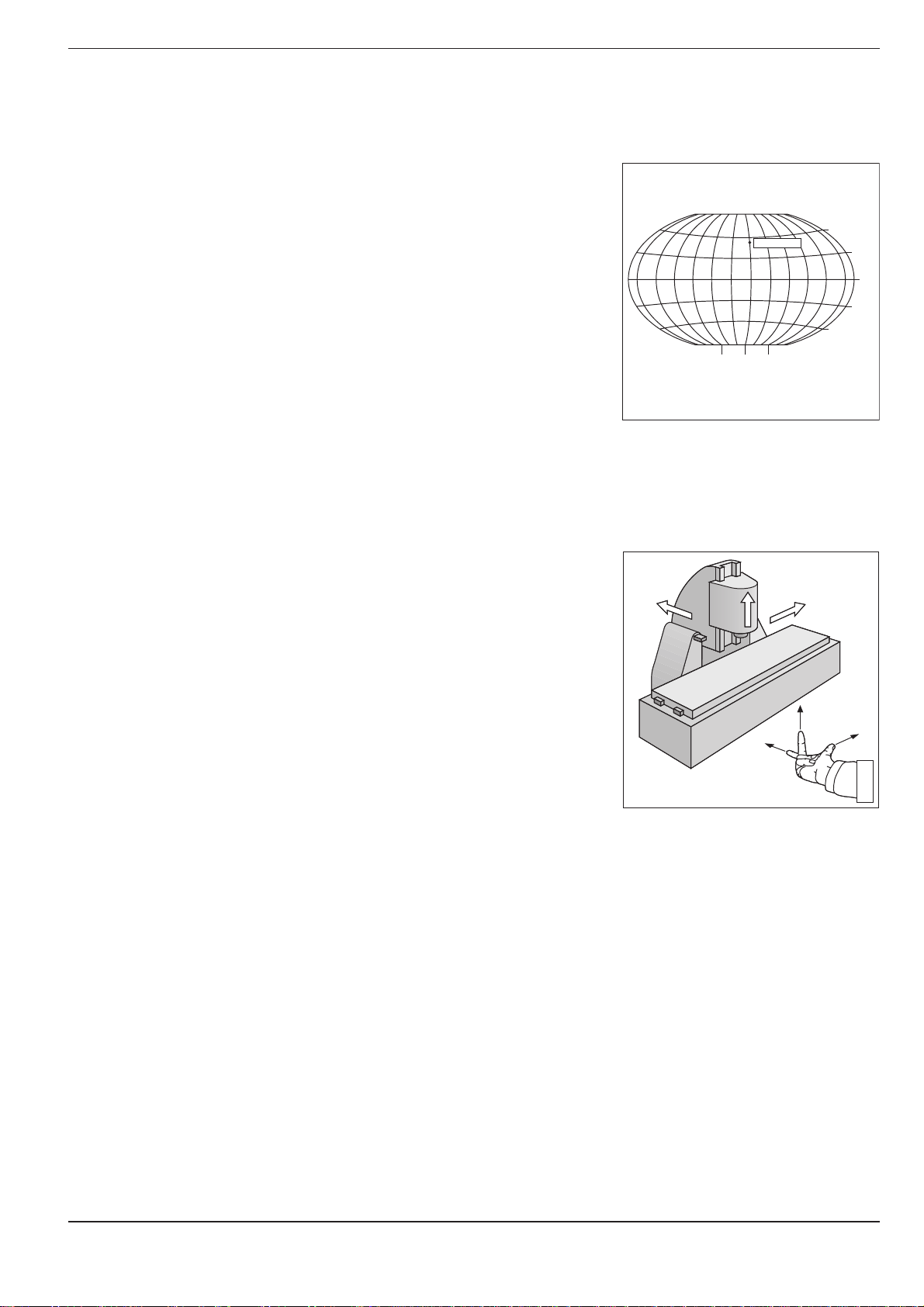
Reference system
In order to define positions one needs a reference system. For example,
positions on the earth's surface can be defined "absolutely" by their
geographic coordinates of longitude and latitude. The term "coordinate"
comes from the Latin word for "that which is arranged", i.e. dimensions
used for determining or defining positions. The network of horizontal and
vertical lines around the globe constitutes an "absolute reference system"
– in contrast to the "relative" definition of a position that is referenced, for
example, to some other, known location.
Cartesian coordinate system
On a TNC controlled milling machine a workpiece is normally machined
according to a workpiece-referenced Cartesian coordinate system (a
rectangular coordinate system named after the French mathematician and
philosopher René Descartes, Latin: Renatus Cartesius; 1596 to 1650). The
Cartesian coordinate system is based on three coordinate axes X, Y and Z,
which are parallel to the machine guideways. The figure to the right
illustrates the "right hand rule" for remembering the three axis directions:
the middle finger is pointing in the positive direction of the tool axis from
the workpiece toward the tool (the Z axis), the thumb is pointing in the
positive X direction, and the index finger in the positive Y direction.
Fig. 1.8: The geographic coordinate system
is an absolute reference system
Fig. 1.9: Designations and directions of the
axes on a milling machine
TNC 360 1-7
Page 25
1 Introduction
1.2 Fundamentals of NC
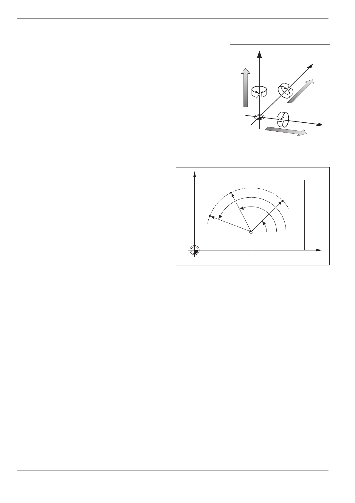
Additional axes
The TNC can control machines that have more than three axes. U, V and
W are secondary linear axes parallel to the main axes X, Y and Z, respec-
tively (see illustration). Rotary axes are also possible. They are designated
as axes A, B and C.
W+
Z
Y
C+
B+
V+
A+
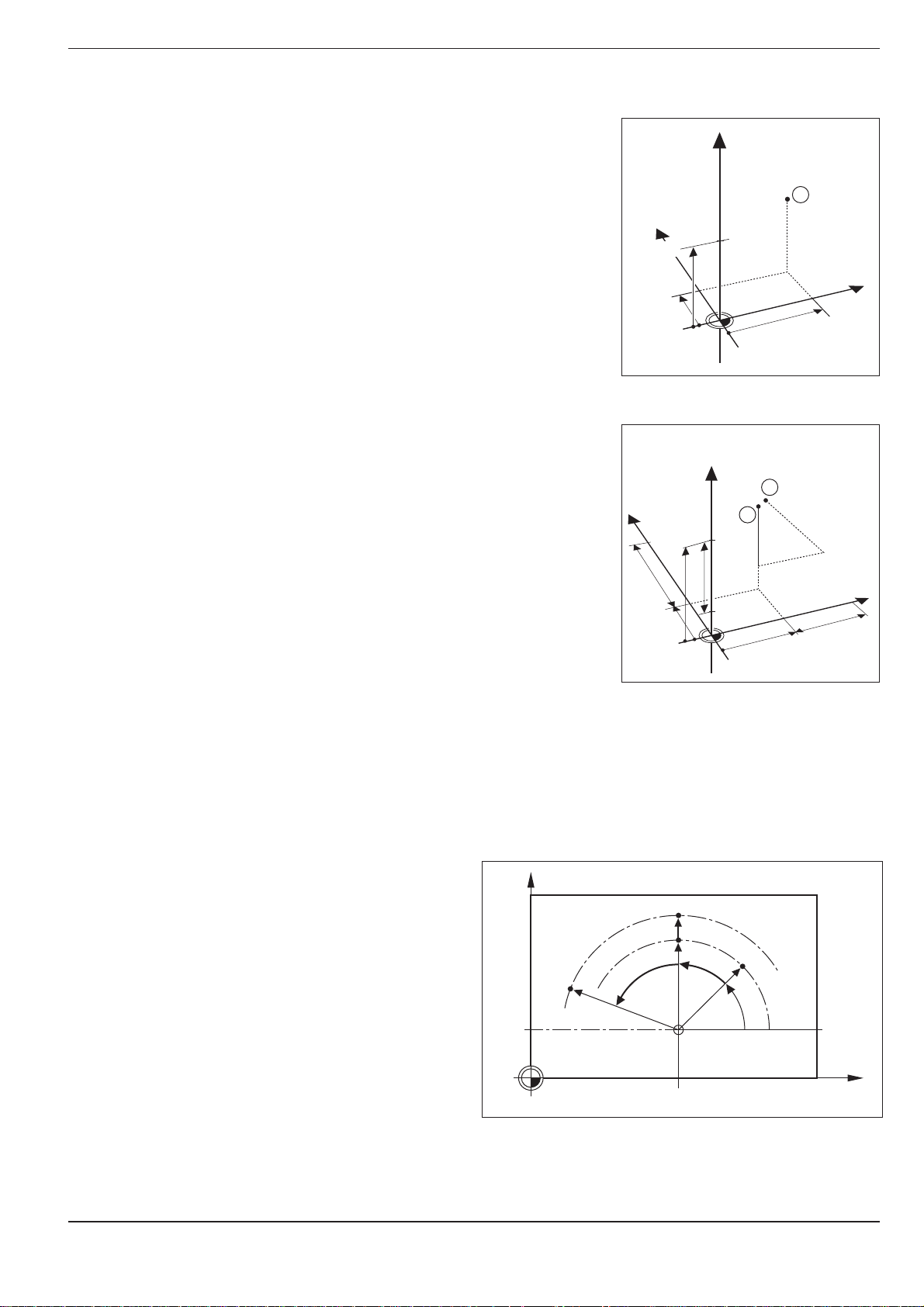
Polar coordinates
The Cartesian coordinate system is especially
useful for parts whose dimensions are mutually
perpendicular. But when workpieces contain
circular arcs, or when dimensions are given in
degrees, it is often easier to use polar coordinates.
In contrast to Cartesian coordinates, which are
three-dimensional, polar coordinates can only
describe positions in a plane.
The datum for polar coordinates is the pole I, J, K.
To describe a position in polar coordinates, think of
a scale whose zero point is rigidly connected to the
pole but which can be freely rotated in a plane
around the pole.
Positions in this plane are defined by:
• Polar Radius R: The distance from the pole I, J
to the defined position.
• Polar Angle H: The angle between the refer-
ence axis and the scale.
U+
Fig. 1.10: Arrangement and designation of
the auxiliary axes
Y
R
H
3
R
J = 10
Fig. 1.11: Positions on an arc with polar coordinates
H
I = 30
R
2
H
1
X
0
°
X
TNC 3601-8
Page 26
1 Introduction
Y
X
Z
1.2 Fundamentals of NC
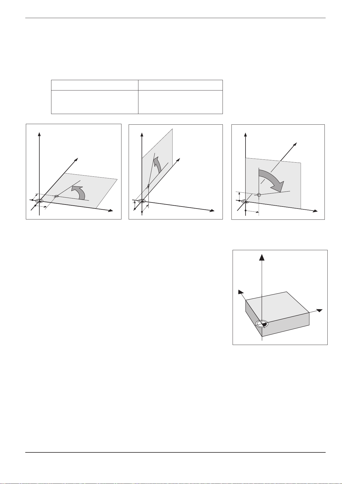
Setting the pole
The pole is defined by setting two Cartesian coordinates. These two
coordinates also determine the reference axis for the polar angle PA.
Coordinates of the pole Reference axis of the angle
I, J +X
J, K +Y
K, I +Z
Z
Z
Y
+
J
I
Fig. 1.12: Polar coordinates and their associated reference axes
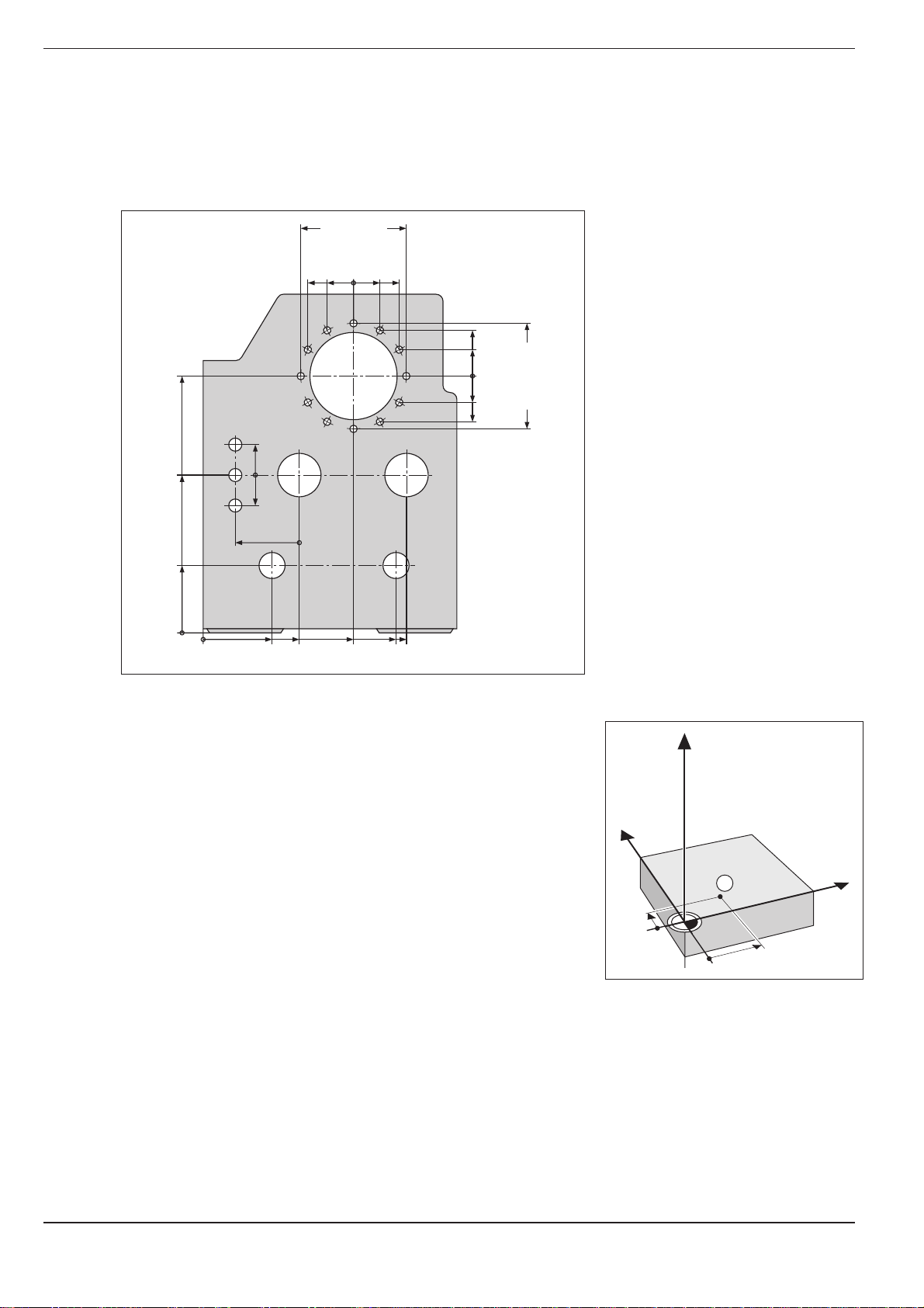
Setting the datum
The workpiece drawing identifies a certain prominent point on the workpiece (usually a corner) as the "absolute datum" and perhaps one or more
other points as relative datums. The process of datum setting establishes
these points as the origin of the absolute or relative coordinate systems:
The workpiece, which is aligned with the machine axes, is moved to a
certain position relative to the tool and the display is set either to zero or
to another appropriate position value (e.g. to compensate the tool radius).
0°
X
K
J
+
Z
Y
Y
0°
0°
+
K
X
I
X
Fig. 1.13: The workpiece datum serves as
the origin of the Cartesian
coordinate system
TNC 360 1-9
Page 27
1 Introduction
Y
X
Z
1
10
5
1.2 Fundamentals of NC
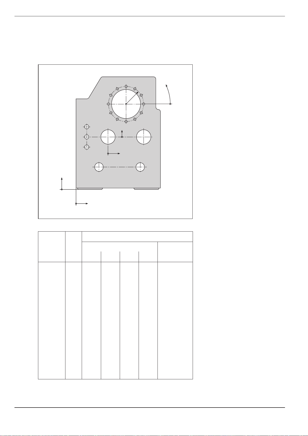
Example:
Drawings with several relative datums
(according to ISO 129 or DIN 406, Part 11; Figure 171)
1225
750
320
125
250
216,5
216,5
250
-250
-125
-216,5
0
125
0
-125
-216,5
-250
150
0
-150
300±0,1
0
0
0
325
450
700
900
950
Example:
Coordinates of the point ➀:
X = 10 mm
Y = 5 mm
Z = 0 mm
The datum of the Cartesian coordinate system is located 10 mm away
from point ➀ on the X axis and 5 mm on the Y axis.
The 3D Touch Probe System from HEIDENHAIN is an especially
convenient and efficient way to find and set datums.
Fig. 1.15: Point ➀ defines the coordinate
system.
TNC 3601-10
Page 28
1 Introduction
Y
X
Z
1
20
10
Z=15mm
X=20mm
Y=10mm
15
I
Z=–15mm
Y
X
Z
2
10
5
5
15
20
10
10
I
X=10mm
I
Y=10mm
3
0
0
1.2 Fundamentals of NC
Absolute workpiece positions
Each position on the workpiece is clearly defined by its absolute coordinates.
Example: Absolute coordinates of the position ➀:
X = 20 mm
Y = 10 mm
Z = 15 mm
If you are drilling or milling a workpiece according to a workpiece drawing
with absolute coordinates, you are moving the tool to the coordinates.
Incremental workpiece positions
A position can be referenced to the previous nominal position: i.e. the
relative datum is always the last programmed position. Such coordinates
are referred to as incremental coordinates (increment = growth), or also
incremental or chain dimensions (since the positions are defined as a
chain of dimensions). Incremental coordinates are designated with G91.
Example: Incremental coordinates of the position ➂
referenced to position ➁
Absolute coordinates of the position ➁ :
X = 10 mm
Y = 5 mm
Z = 20 mm
Incremental coordinates of the position ➂ :
IX = 10 mm
IY = 10 mm
IZ = –15 mm
If you are drilling or milling a workpiece according to a workpiece drawing
with incremental coordinates, you are moving the tool by the coordinates.
An incremental position definition is therefore intended as an immediately
relative definition. This is also the case when a position is defined by the
distance-to-go to the target position (here the relative datum is located at
the target position). The distance-to-go has a negative algebraic sign if the
target position lies in the negative axis direction from the actual position.
The polar coordinate system can also express both
types of dimensions:
• Absolute polar coordinates always refer to the
pole I, J and the angle reference axis.
• Incremental polar coordinates always refer to
Y
the last programmed nominal position of the
tool.
Fig. 1.16: Position ➀ of the example
"absolute workpiece positions"
Fig. 1.17: Positions ➁ and ➂ of the example
"incremental workpiece positions"
G91R
R
G91H G91H
R
J = 10
R
H
0°
TNC 360 1-11
Fig. 1.18: Incremental dimensions in polar coordinates (designated
with "G91")
I = 30
X
Page 29
1 Introduction
1.2 Fundamentals of NC
Example:
Workpiece drawing with coordinate dimensioning
(according to ISO 129 or DIN 406, Part 11; Figure 179)
2.1
2.2
2.3
3.4
3.5
3.6
r
3.7
3
3.8
3.9
3.10
Y2
2 1.3
X2
3.3
3.11
3.2
3.1
3.12
ϕ
1.21.1
Y1
1
X1
Dimensions in mm
Coordinate Coordinates
origin
Pos. X1 X2 Y1 Y2 r ϕ d
11 00 1 1.1 325 320 Ø 120 H7
1 1.2 900 320 Ø 120 H7
1 1.3 950 750 Ø 200 H7
1 2 450 750 Ø 200 H7
1 3 700 1225 Ø 400 H8
2 2.1 –300 150 Ø 50 H11
2 2.2 –300 0 Ø 50 H11
2 2.3 –300 –150 Ø 50 H11
3 3.1 250 0° Ø 26
3 3.2 250 30° Ø 26
3 3.3 250 60° Ø 26
3 3.4 250 90° Ø 26
3 3.5 250 120° Ø 26
3 3.6 250 150° Ø 26
3 3.7 250 180° Ø 26
3 3.8 250 210° Ø 26
3 3.9 250 240° Ø 26
3 3.10 250 270° Ø 26
3 3.11 250 300° Ø 26
3 3.12 250 330° Ø 26
TNC 3601-12
Page 30
1 Introduction
Y
X
Z
1.2 Fundamentals of NC
Programming tool movements
An axis position is changed either by moving the tool or by moving the
machine table on which the workpiece is fixed, depending on the individual machine tool.
You always program as if the tool is moving and the workpiece is
stationary.
If the machine table moves in one or several axes, the corresponding axes
are designated on the machine operating panel with a prime mark (e.g. X’,
Y’). When an axis is designated with a prime mark, the programmed
direction of axis movement is the opposite direction of tool movement
relative to the workpiece.
+Y
+Z
+X
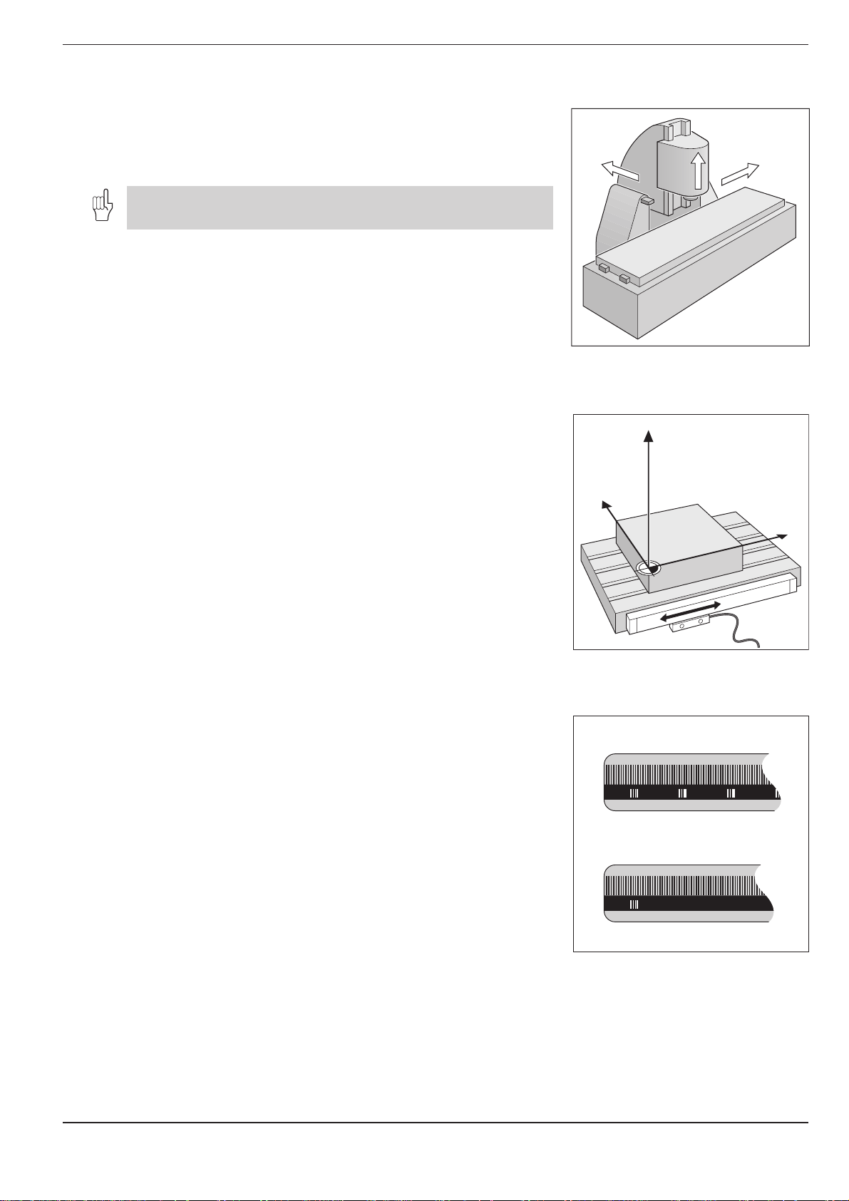
Position encoders
The position encoders – linear encoders for linear axes, angle encoders for
rotary axes – convert the movement of the machine axes into electrical
signals. The control evaluates these signals and constantly calculates the
actual position of the machine axes.
If there is an interruption in power, the calculated position will no longer
correspond to the actual position. When power is returned, the TNC can
re-establish this relationship.
Reference marks
The scales of the position encoders contain one or more reference marks.
When a reference mark is passed over, it generates a signal which
identifies that position as the machine axis reference point.
With the aid of these reference marks the TNC can re-establish the
assignment of displayed positions to machine axis positions.
Fig. 1.20: On this machine the tool moves in
the Y and Z axes; the machine
table moves in the positive X' axis
direction.
Fig. 1.21: Linear position encoder, here for
the X axis
If the position encoders feature distance-coded reference marks, each
axis need only move a maximum of 20 mm (0.8 in.) for linear encoders,
and 20° for angle encoders.
Fig. 1.22: Linear scales: above with
distance-coded-reference marks,
below with one reference mark
TNC 360 1-13
Page 31

1 Introduction
1.3 Switch-On
Switch on the power supply for the TNC and machine. The TNC then
begins the following dialog:
MEMORY TEST
The TNC memory is automatically checked.
POWER INTERRUPTED
Message from the TNC indicating that the power was interrupted.
Clear the message.
TRANSLATE PLC PROGRAM
The PLC program of the TNC is automatically translated.
RELAY EXT. DC VOLTAGE MISSING
Switch on the control voltage.
The TNC checks the functioning of the EMERGENCY STOP circuit.
MANUAL OPERATION
TRAVERSE REFERENCE POINTS
To cross over the reference marks in the displayed sequence:
Press the machine START button for each axis.
To cross over the reference marks in any sequence:
For each axis, press and hold down the machine axis direction
button until the reference mark has been crossed over.
CE
I
I
X
, , ...
Y
The TNC is now ready for operation
in the MANUAL OPERATION mode.
TNC 3601-14
Page 32

1 Introduction
1.4 Graphics and Status Display
The TNC features various graphic display modes for testing programs. To
be able to use this feature, you must select a program run operating
mode.
Workpiece machining is simulated graphically in the display modes:
• Plan view
• Projection in three planes
• 3D view
With the fast internal image generation, the TNC calculates the contour
and displays a graphic only of the completed part.
Select display mode
GRAPHICS
MOD
2 x
Select display mode menu.
Plan view
Select desired display mode.
ENT
Confirm selection.
Start graphic display
GRAPHICS
START
Start graphic simulation in the selected display mode.
The START key repeats a graphic simulation as often as desired.
Rotary axis movements cannot be graphically simulated.
An attempted test run will result in an error message.
In this mode, contour height is shown by image brightness.
The deeper the contour, the darker the image.
Number of depth levels: 7
This is the fastest of the three display modes.
Fig. 1.23: TNC graphics, plan view
TNC 360 1-15
Page 33

1 Introduction
1.4 Graphics and Status Display
Projection in three planes
Here the program is displayed as in a technical
drawing, with a plan view and two orthographic
sections. A conical symbol near the graphic indicates whether the display is in first angle or second
angle projection according to ISO 6433, Part 1. The
type of projection can be selected with MP 7310.
Moving the sectional planes
The sectional planes can be moved to any position
with the arrow keys. The position of the sectional
plane is displayed on the screen while it is being
moved.
3D view
This mode displays the simulated workpiece in
three-dimensional space.
Fig. 1.24: TNC graphics, projection in three planes
Fig. 1.25: TNC graphics, 3D view
Rotating the 3D view
In the 3D view, the image can be rotated around
the vertical axis with the horizontal arrow keys.
The angle of orientation is indicated with a special
symbol:
0
0
rotation
900 rotation
1800 rotation
0
rotation
270
Fig. 1.26: Rotated 3D view
3D view, not true to scale
If the height-to-side ratio is between 0.5 and 50, a non-scaled 3D view can
be selected with the vertical arrow keys. This view improves the resolution of the shorter workpiece side.
The angle orientation symbol also indicates the angle of orientation of the
non-scaled 3D view.
TNC 3601-16
Page 34

1 Introduction
1.4 Graphics and Status Display
Detail magnification of a 3D graphic
Fig. 1.27: Detail magnification of a 3D graphic
GRAPHICS
MAGN
Select function for detail magnification.
Select sectional plane.
Set / reset section.
If desired: switch dialog for transfer of detail.
TRANSFER DETAIL = ENT
ENT
Magnify detail.
Details can be magnified in any display mode. The abbreviation MAGN appears on the screen to indicate that the
image is magnified.
Return to non-magnified view
GRAPHICS
BLK
FORM
Press BLK FORM to display the workpiece in its programmed size.
TNC 360 1-17
Page 35

1 Introduction
1.4 Graphics and Status Display
Status Display
The status display in a program run operating mode
shows the current coordinates as well as the
following information:
• Type of position display (ACTL, NOML, ...)
• Axis locked ( in front of the axis)
• Number of current tool T
• Tool axis
• Spindle speed S
• Feed rate F
• Active miscellaneous function M
• TNC is in operation (indicated by ❊)
• Machines with gear ranges:
Gear range following "/" character
(depends on machine parameter)
Bar graphs can be used to indicate analog quantities such as spindle speed and feed rate in the status display. These
bar graphs must be activated by the machine tool builder.
Fig. 1.28: Status display in a program run operating mode
TNC 3601-18
Page 36

1 Introduction
1.5 Programs
The TNC 360 can store up to 32 part programs at once. The part programs
can be written in HEIDENHAIN plain language dialog or according to ISO.
ISO programs are indicated with “ISO”.
Each program is identified by a number with up to eight characters.
Program directory
The program directory is called with the PGM NR
key. To erase programs in the TNC memory, press
the CL PGM key.
The program directory provides the following
information:
• Program number
• Program type (HEIDENHAIN or ISO)
• Program size in bytes, where one byte is the
equivalent of one character.
Action Mode of Call program
operation directory with...
Create (a program) ...
Edit ...
Erase ...
Test ...
Execute ...
Fig. 1.29: Program management functions
PGM
NR
PGM
NR
CL
PGM
PGM
NR
PGM
NR
Fig. 1.30: Program directory on the TNC screen
TNC 360 1-19
Page 37

1 Introduction
1.5 Programs
Selecting, erasing and protecting programs
To select a program:
PGM
NR
PROGRAM NUMBER ?
or
1
5
ENT
To erase a program:
CL
PGM
ERASE = ENT / END = NO ENT
or
Call the program management.
Use the arrow keys to highlight the program.
Enter the desired program number, for example 15.
Confirm your selection.
Press CL PGM to call the program management.
Use the arrow keys to highlight the program.
or
NO
ENT
Erase the program or abort.
ENT
To protect a program:
PGM
NR
Call the program management.
PROGRAM NUMBER = ?
e.g.
ENT
ENT
5
Enter the number of the program to be protected, for example
program number 5.
Use the arrow key to highlight the first block.
G
END
0
5
Enter the function for program protection, conclude the block.
Resulting NC block: %5 G71 G50 *
Removing edit protection
To remove edit protection re-select the program and enter the code
number 86357 with the corresponding MOD function (see page 10-3).
TNC 3601-20
Page 38

1 Introduction
1.5 Programs
To remove edit protection:
Select the protected program, for example program number 5.
0 BEGIN 5 MM P
MOD
VACANT BYTES =
repeatedly
CODE NUMBER
8 6
3
5 7
Select MOD functions.
Activate the CODE NUMBER function.
Enter the code number 86357:
Edit protection is removed, the "P" disappears.
TNC 360 1-21
Page 39

2 Manual Operation and Setup
2.1 Moving the Machine Axes
Traversing with the machine axis direction buttons
MANUAL OPERATION
e.g.
X
You can move several axes at once in this way.
For continuing movement:
MANUAL OPERATION
e.g.
Y
together
You can only move one axis at a time with this method.
I
Press the machine axis direction button and hold it for as long as you wish
the axis to move.
Press and hold the machine axis direction button, then press the machine
START button. The axis continues to move after you release the keys.
To stop the axis, press the machine STOP button.
TNC 3602-2
Page 40

2 Manual Operation and Setup
2.1 Moving the Machine Axes
Traversing with the electronic handwheel
ELECTRONIC HANDWHEEL
INTERPOLATION FACTOR: 1 3
e.g.
e.g.
Now move the selected axis with the electronic handwheel. If you are
using the portable handwheel, first press the enabling switch on its back.
Interpolation
factor
0
1
2
3
4
5
6
7
8
9
10
Fig. 2.1: Interpolation factors and paths of traverse
ENT
3
X
Traverse in mm per
revolution
20.000
10.000
Enter the desired interpolation factor (see table below).
Select the axis that you wish to move:
for portable handwheels, at the handwheel;
for integral handwheels, at the TNC keyboard.
5.000
2.500
1.250
0.625
0.312
0.156
0.078
0.039
0.019
Fig. 2.2: HR 330 Electronic Handwheel
The smallest programmable interpolation factor depends on the individual machine tool.
Positioning with the electronic handwheel can also be carried out in the operating mode PROGRAMMING AND
EDITING (depending on MP7641).
Working with the HR 330 Electronic Handwheel
Attach the electronic handwheel to a steel surface with the mounting
magnets such that it cannot be operated unintentionally.
Be sure not to press the axis direction buttons unintentionally when you
remove the handwheel from its position as long as the enabling switch
(between the magnets) is depressed.
If you are using the handwheel for machine setup, press the enabling
switch. Only then can you move the axes with the axis direction buttons.
TNC 360 2-3
Page 41

2 Manual Operation and Setup
Z
X
8 8
816
2.1 Moving the Machine Axes
Incremental jog positioning
With incremental jog positioning, a machine axis will move by a preset
increment each time you press the corresponding machine axis
direction button.
Fig. 2.3: Incremental jog positioning in the
ELECTRONIC HANDWHEEL
INTERPOLATION FACTOR: 4
Select incremental jog positioning.
Select incremental jog positioning by pressing the handwheel mode
key again.
ELECTRONIC HANDWHEEL
JOG-INCREMENT: 4 8
e.g.
e.g.
ENT
8
X
Enter the jog increment, for example 8 mm.
Press the machine axis direction button as often as desired.
X axis
Incremental jog positioning must be enabled by the machine tool builder.
Positioning with manual data input (MDI)
Page 5-41 describes positioning by manually entering the target coordinates for the tool.
TNC 3602-4
Page 42

2 Manual Operation and Setup
2.2 Spindle Speed S, Feed Rate F and Miscellaneous Function M
The following values can be entered and changed in the MANUAL OPERATION and ELECTRONIC HANDWHEEL modes of operation:
• Miscellaneous function M
• Spindle speed S
• Feed rate F (can be changed but not entered)
For part programs these functions are entered or edited directly in the
PROGRAMMING AND EDITING operating mode.
To enter the spindle speed S
S
N10 S
e.g.
A miscellaneous function M starts spindle rotation at the entered
speed S.
0
0
1
0
I
END
Fig. 2.4: Knobs for spindle speed and feed
rate overrides
Select the S function key.
Enter the spindle speed S, for example 1000 rpm.
Confirm the spindle speed S with the machine START button.
TNC 360 2-5
Page 43

2 Manual Operation and Setup
2.2 Spindle Speed S, Feed Rate F and Miscellaneous Function M
To enter the miscellaneous function M
M
N10 M
ENT
6
e.g.
I
Chapter 11 provides an overview of the miscellaneous functions.
To change the spindle speed S
100
15050
S %
0
The spindle speed override will function only if your machine tool is equipped with a stepless spindle drive.
Select the M function key.
Enter the desired miscellaneous function M, for example M6.
Activate the miscellaneous function M with the machine START button.
Turn the spindle speed override knob:
Adjust the spindle speed S to between 0% and 150% of the last entered
value.
To change the feed rate F
In the MANUAL OPERATION mode the feed rate is set through a machine
parameter.
100
0
15050
F %
Turn the feed rate override knob:
Adjust the feed rate to between 0% and 150% of the last entered value.
TNC 3602-6
Page 44

2 Manual Operation and Setup
2.3 Setting the Datum without a 3D Touch Probe
You fix a datum by setting the TNC position display to the coordinates of a
known point on the workpiece. The fastest, easiest and most accurate
way of setting the datum is by using a 3D touch probe system from
HEIDENHAIN (see page 2-14).
To prepare the TNC:
Clamp and align the workpiece.
Insert the zero tool with known radius into the spindle.
Select the MANUAL OPERATION mode.
Ensure that the TNC is showing actual position values (see p. 10-4).
Setting the datum in the tool axis
Protective arrangement:
If the workpiece surface must not be scratched,
you can lay a metal shim of known thickness d
on it. Then enter a tool axis datum value that is
larger than the desired datum by the value d.
Move the tool until it touches workpiece surface.
e.g.
Z
Z
Fig. 2.5: Datum setting in the tool axis; right with protective shim
Select the tool axis.
Z
d
X
X
DATUM SET Z =
ENT
0
e.g.
5 0
e.g.
TNC 360 2-7
ENT
For a zero tool: Set the display to Z = 0 or enter thickness d of the shim.
For a preset tool: Set the display to the length L of the tool,
for example Z=50 mm, or enter the sum Z=L+d.
Page 45

2 Manual Operation and Setup
2.3 Setting the Datum without a 3D Touch Probe
Setting the datum in the working plane
Move the zero tool until it touches the side of the workpiece.
X
e.g.
e.g.
+
/
ENT
5
Y
1
Y
–R
–R
2
X
1
Fig. 2.6: Setting the datum in the working plane; plan view (upper
right)
Select the axis.
Enter the position of the tool center (here X = –5 mm) in the selected axis.
Be careful to enter the correct algebraic sign.
2
X
Repeat the process for all axes in the working plane.
TNC 3602-8
Page 46

2 Manual Operation and Setup
2.4 3D Touch Probe System
3D Touch probe applications
The TNC provides touch functions for application of a HEIDENHAIN 3D
touch probe. Typical applications for the touch probe system are:
• Compensating workpiece misalignment
(basic rotation)
• Datum setting
• Measuring:
- Lengths and positions on the workpiece
- Angles
- Circle radii
- Circle centers
• Measurements under program control
• Digitizing 3D surfaces (optional, only available with HEIDENHAIN plain
language dialog programming.)
The TNC must be specially prepared by the machine tool builder for the use of a 3D touch probe.
After you press the machine START button, the touch probe begins
executing the selected probe function. The machine tool builder sets the
feed rate F at which the probe approaches the workpiece. When the 3D
touch probe contacts the workpiece, it
• transmits a signal to the TNC, which stores the coordinates of the
probed position
• stops moving
• returns to its starting position in rapid traverse
Selecting the touch probe menu
Fig. 2.7: HEIDENHAIN TS 120 three-
dimensional touch probe system
F
F
max
Fig. 2.8: Feed rates during probing
F
MANUAL OPERATION
or
ELECTRONIC HANDWHEEL
TOUCH
PROBE
CALIBRATION EFFECTIVE LENGTH
CALIBRATION EFFECTIVE RADIUS
BASIC ROTATION
SURFACE = DATUM
CORNER = DATUM
CIRCLE CENTER = DATUM
TNC 360 2-9
Select the menu of touch probe functions.
Page 47

2 Manual Operation and Setup
2.4 3D Touch Probe System
Calibrating the 3D Touch Probe
The touch probe system must be calibrated
• for commissioning
• after a stylus breaks
• when the stylus is changed
• when the probe feed rate is changed
• in case of irregularities, such as those resulting from machine heating.
During calibration, the TNC finds the “effective” length of the stylus and
the “effective” radius of the ball tip. To calibrate the 3D touch probe,
clamp a ring gauge with known height and known internal radius to the
machine table.
To calibrate the effective length
Set the datum in the tool axis such that for the machine tool table, Z=0.
TOUCH
PROBE
SURFACE = DATUM
Z
Y
5
X
Fig. 2.9: Calibrating the touch probe length
ENT
CALIBRATION EFFECTIVE LENGTH
TOOL AXIS = Z
e.g.
Z
5
e.g.
Move the touch probe to a position just above the ring gauge.
or
I
Select the calibration function for the touch probe length.
Z+ Z–
If necessary, enter the tool axis, for example Z.
Move the highlight to DATUM.
Enter the height of the ring gauge, for example 5 mm.
If necessary, change the displayed traverse direction.
The 3D touch probe contacts the upper surface of the ring gauge.
TNC 3602-10
Page 48

2 Manual Operation and Setup
2.4 3D Touch Probe System
To calibrate the effective radius
Position the ball tip in the bore hole of the ring gauge.
Z
Y
10
X
Fig. 2.10: Calibrating the touch probe radius
TOUCH
PROBE
Displaying calibration values
The effective length and radius of the 3D touch probe are stored in the
TNC for use whenever the touch probe is needed again. The stored values
are displayed the next time the calibration function is called.
SURFACE = DATUM
ENT
CALIBRATION EFFECTIVE RADIUS
X+ X– Y+ Y–
RADIUS RING GAUGE = 0
ENT
5
4 x
I
Select the calibration function for the ball-tip radius.
Select RADIUS RING GAUGE.
Enter the radius of the ring gauge, for example 5 mm.
The 3D touch probe contacts one position on the bore for each axis
direction.
TNC 360 2-11
Page 49

2 Manual Operation and Setup
2.4 3D Touch Probe System
Compensating workpiece misalignment
The TNC electronically compensates workpiece
misalignment by computing a “basic rotation.”
Set the ROTATION ANGLE to the angle at which a
workpiece surface should be oriented with respect
to the angle reference axis (see p. 1-9) of the
working plane.
PA
2
1
A B
TOUCH
PROBE
SURFACE = DATUM
ENT
Select the BASIC ROTATION probe function.
BASIC ROTATION
X+ X- Y+ Y–
ROTATION ANGLE =
e.g.
ENT
0
Enter the nominal value of the ROTATION ANGLE.
Move the ball tip to a starting position
X + X – Y + Y –
or
Select the probing direction.
Fig. 2.11: Basic rotation of a workpiece, probing procedure for com-
near the first touch point 1.
A
pensation (right). The dashed line is the nominal position;
the angle PA is being compensated.
I
Move the ball tip to a starting position
I
Probe the workpiece.
near the second touch point 2.
B
Probe the workpiece.
A basic rotation is kept in non-volatile storage and is effective for all
subsequent program runs and graphic simulations.
TNC 3602-12
Page 50

2 Manual Operation and Setup
2.4 3D Touch Probe System
Displaying basic rotation
The angle of the basic rotation is shown in the
rotation angle display. When a basic rotation is
active the abbreviation ROT is highlighted in the
status display.
To cancel a basic rotation:
Select BASIC ROTATION again.
Fig. 2.12: Displaying the angle of an active basic rotation
ROTATION ANGLE =
ENT
0
END
Set the ROTATION ANGLE to 0.
Terminate the probe function.
TNC 360 2-13
Page 51

2 Manual Operation and Setup
Y
X
Z
1
2.5 Setting the Datum with the 3D Touch Probe System
The following functions for setting the datum on an aligned workpiece are
listed for in the TCH PROBE menu:
• Datum setting in any axis with
SURFACE = DATUM
• Setting a corner as datum with
CORNER = DATUM
• Setting the datum at a circle center with
CIRCLE CENTER = DATUM
Setting the datum in a specific axis
Select the probe function SURFACE = DATUM.
Move the touch probe to a starting position near the touch point.
SURFACE = DATUM
X + X – Y + Y – Z + Z –
Select the probing direction and the axis in which you wish to set the datum,
for example Z in the Z– direction.
Probe the workpiece.
Enter the nominal coordinate of the DATUM.
e.g.
or
I
ENT
0
Fig. 2.13: Probing for the datum in the Z axis
TNC 3602-14
Page 52

2 Manual Operation and Setup
2.5 Setting the Datum with the 3D Touch Probe System
Corner as datum
Y
Y=?
Fig. 2.14: Probing procedure for finding the coordinates of the
Select the CORNER = DATUM probe function.
To use the points that were just probed for a basic rotation:
TOUCH POINTS OF BASIC ROTATION?
ENT
Transfer the touch point coordinates to memory.
X=?
corner P
Y
4
3
1
P
P
X
2
X
Move the touch probe to a starting position near the first touch point on the side that was not probed for basic
rotation.
CORNER = DATUM
X + X – Y + Y –
or
I
Move the touch probe to a starting position near the second touch point on the same side.
I
DATUM X =
e.g.
ENT
0
Select the probing direction.
Probe the workpiece.
Probe the workpiece.
Enter the first coordinate of the datum, for example in the X axis.
.
.
.
TNC 360 2-15
Page 53

2 Manual Operation and Setup
2.5 Setting the Datum with the 3D Touch Probe System
.
.
.
Select the second coordinate.
DATUM Y =
e.g.
ENT
0
END
Enter the second coordinate of the datum, for example in the Y axis.
Terminate the probe function.
If you do not wish to use points that were just probed for a basic rotation:
TOUCH POINTS OF BASIC ROTATION?
NO
ENT
Ignore the dialog prompt.
Probe both workpiece sides twice.
Enter the datum coordinates.
TNC 3602-16
Page 54

2 Manual Operation and Setup
2.5 Setting the Datum with the 3D Touch Probe System
Circle center as datum
With this function you can set the datum at the center of bore holes,
circular pockets, cylinders, journals, circular islands etc.
Inside circle
The TNC automatically probes the inside wall in all four coordinate axis
directions.
For incomplete circles (circular arcs) you can choose the appropriate
probing direction.
Y
10
Y+
X–
X+
Y–
Select the CIRCLE CENTER = DATUM probe function.
Move the touch probe to a position approximately in the center of the circle.
CIRCLE CENTER = DATUM
X + X – Y + Y –
4 x
DATUM X =
e.g.
I
ENT
8
The probe touches four points on the inside of the circle.
Enter the first coordinate of the circle center, for example in the X axis.
8
Fig. 2.15: Probing an inside cylindrical
surface to find the center
X
Select the second coordinate.
DATUM Y =
e.g.
1
TNC 360 2-17
0
END
ENT
Enter the second coordinate of the circle center, for example in the Y axis.
Terminate the probe function.
Page 55

2 Manual Operation and Setup
Y
X
X–
X+
Y+
Y–
3
1
2
4
2.5 Setting the Datum with the 3D Touch Probe System
Outside circle
Select the CIRCLE CENTER = DATUM probe function.
Move the touch probe to a starting position near the first touch point
CIRCLE CENTER = DATUM
X + X – Y + Y –
or
I
Repeat the probing process for points
Select the probing direction.
Probe the workpiece.
and 4 (see Fig. 2.16).
2, 3
Enter the coordinates of the circle center.
Fig. 2.16: Probing an outside cylindrical
outside of the circle.
1
surface to find the center
After the probing procedure is completed, the TNC displays the coordinates of the circle center and the circle radius PR.
TNC 3602-18
Page 56

2 Manual Operation and Setup
2.6 Measuring with the 3D Touch Probe System
With the 3D touch probe system you can determine
• Position coordinates, and from them,
• dimensions and angles on the workpiece.
Finding the coordinate of a position on an aligned workpiece
Select the SURFACE = DATUM probe function.
Move the touch probe to a starting position near the touch point.
SURFACE = DATUM
X + X – Y + Y – Z + Z –
or
I
The TNC displays the coordinate of the touch point as DATUM.
Select the probing direction and the axis in which you wish to find the
coordinate.
Probe the workpiece.
Finding the coordinates of a corner in the working plane
Find the coordinates of the corner point as described under “Corner as
datum.” The TNC displays the coordinates of the probed corner as
DATUM.
TNC 360 2-19
Page 57

2 Manual Operation and Setup
2.6 Measuring with the 3D Touch Probe System
Measuring workpiece dimensions
Select the SURFACE = DATUM probe function.
Move the probe to a starting position near the first touch point 1.
SURFACE = DATUM
X + X – Y + Y – Z + Z –
or
Use the arrow keys to select the probing direction.
Y
2
l
Z
Fig. 2.17: Measuring lengths with the 3D
touch probe
1
X
I
If you will need the current datum later, write down the value that appears in the DATUM display.
DATUM X =
ENT
0
END
Re-select the SURFACE = DATUM probe function.
Move the touch probe to a starting position near the second touch point
Probe the workpiece.
Set the DATUM to 0.
Terminate the dialog.
.
2
.
.
.
TNC 3602-20
Page 58

2 Manual Operation and Setup
2.6 Measuring with the 3D Touch Probe System
.
.
.
SURFACE = DATUM
X + X – Y + Y – Z + Z –
or
I
The value displayed as DATUM is the distance between the two points on
the coordinate axis.
To return to the datum that was active before the length measurement:
Select the SURFACE = DATUM probe function.
Probe the first touch point again.
Set the datum to the value that you wrote down previously.
END
Select the probing direction with the arrow keys –
same axis as for 1.
Probe the workpiece.
Terminate the dialog.
Measuring angles
You can also use the 3D touch probe system to measure angles in the
working plane. You can measure
• the angle between the angle reference axis and a workpiece side, or
• the angle between two sides.
The measured angle is displayed as a value of maximum 90°.
To find the angle between the angle reference axis and a side of the workpiece:
Select the BASIC ROTATION probe function.
ROTATION ANGLE =
If you will need the current basic rotation later, write down the value that appears under ROTATION ANGLE.
Make a basic rotation with the side of the workpiece (see “Compensating workpiece misalignment”).
.
.
.
TNC 360 2-21
Page 59

2 Manual Operation and Setup
2.6 Measuring with the 3D Touch Probe
.
.
.
The angle between the angle reference axis and the side of the workpiece appears as the ROTATION ANGLE in the
BASIC ROTATION function.
Cancel the basic rotation.
Restore the previous basic rotation by setting the ROTATION ANGLE to the value that you wrote down previously.
To measure the angle between two sides of a workpiece:
PA
Fig. 2.18: Measuring the angle between two
Select the BASIC ROTATION probe function.
ROTATION ANGLE =
If you will need the current basic rotation later, write down the value that appears under ROTATION ANGLE.
Make a basic rotation for the first side (see “Compensating workpiece misalignment“).
Probe the second side as for a basic rotation, but do not set the ROTATION ANGLE to zero!
The angle PA between the workpiece sides appears as the ROTATION ANGLE in the BASIC ROTATION function.
Cancel the basic rotation.
sides of a workpiece
Restore the previous basic rotation by setting the ROTATION ANGLE to the value that you wrote down previously.
TNC 3602-22
Page 60

3 Test Run and Program Run
D
3.1 Test Run
In the TEST RUN mode of operation the TNC checks programs and
program sections for the following errors without moving the machine
axes:
• Geometrical incompatibility
• Missing data
• Impossible jumps
The following TNC functions can be used in the TEST RUN operating
mode:
• Test interruption at any block
• Optional block skip
To do a test run
TEST RUN TO BLOCK NUMBER =
e.g.
NO
ENT
1
ENT
0
Test the entire program.
Test the program up to the entered block, for example block 10.
Test run functions
Function Key
• Interrupt the test run
• Continue test run after interruption
ENT
NO
TNC 3603-2
Page 61

3 Test Run and Program Run
3.2 Program Run
In the PROGRAM RUN / FULL SEQUENCE mode of operation the TNC
executes a part program continuously to its end or up to a program stop.
In the PROGRAM RUN /SINGLE BLOCK mode of operation you execute
each block separately by pressing the machine START button.
The following TNC functions can be used during a program run:
• Interrupt program run
• Start program run from a certain block
• Blockwise transfer of very long programs from external storage
• Checking/changing Q parameters
• Graphic simulation of a program run
To run a part program
• Clamp the workpiece to the machine table.
• Set the datum
• Select the program.
PROGRAM RUN / SINGLE BLOCK
or
PROGRAM RUN / FULL SEQUENCE
Select the part program.
GOTO
ENT
0
Go to the first block of the program.
Run the part program.
I
Only in mode
PROGRAM RUN /
SINGLE BLOCK
Run each block of the part program separately.
I
repeatedly
The feed rate and spindle speed can be changed with the override knobs.
TNC 360 3-3
Page 62

3 Test Run and Program Run
3.2 Program Run
Interrupting machining
There are various ways to interrupt a program run:
• Programmed interruptions
• External STOP key
• Switching to PROGRAM RUN / SINGLE BLOCK
• EMERGENCY STOP button
If the TNC registers an error during program run, it automatically interrupts
machining.
Programmed interruptions
Interruptions can be programmed directly in the part program. The part
program is interrupted at a block containing one of the following entries:
• G38
• Miscellaneous functions M0, M02 or M30
• Miscellaneous function M06, if the machine tool builder has assigned a
stop function
To interrupt or abort machining immediately:
The block which the TNC is currently executing is not completed.
Interrupt machining.
The ❊ sign in the status display blinks.
The part program can be aborted with the D key.
D
The ❊ sign disappears from the status display.
To interrupt machining by switching to the PROGRAM RUN / SINGLE BLOCK operating mode:
You can interrupt the program run at the end of the current block.
Abort program run.
Select PROGRAM RUN / SINGLE BLOCK.
TNC 3603-4
Page 63

3 Test Run and Program Run
3.2 Program Run
Resuming program run after an interruption
When a program run is interrupted the TNC stores:
• The data of the last called tool
• Active coordinate transformations
• The coordinates of the last defined circle center
• The count of a running program section repeat
• The number of the last block that calls a subprogram or a program
section repeat
Resuming program run with the START button
You can resume program run by pressing the machine START button if the
program was interrupted in one of the following ways:
• Pressing the machine STOP button
• A programmed interruption
• Pressing the EMERGENCY STOP button (machine-dependent
function).
Resuming program run after an error
• If the error message is not blinking:
Remove the cause of the error.
CE
Clear the error message from the screen.
Restart the program.
• If the error message is blinking:
ON0I
OFF
Switch off the TNC and the machine.
Remove the cause of the error.
Restart the program.
• If you cannot correct the error:
Write down the error message and contact your repair service agency.
TNC 360 3-5
Page 64

3 Test Run and Program Run
3.3 Blockwise Transfer: Executing Long Programs
Part programs that occupy more memory than the TNC provides can be
“drip fed” block by block from an external storage device.
During program run, the TNC transfers program blocks from a floppy disk
unit or PC through its data interface, and erases them after execution.
To prepare for blockwise transfer:
• Prepare the data interface.
• Configure the data interface with the MOD function (see page 10-3).
• If you wish to transfer a part program from a PC, adapt the TNC and PC
to each other (see pages 9-4 and 11-2).
• Ensure that the transferred program meets the following requirements:
- The highest block number must not exceed 65534. However, the
block numbers can repeat themselves as often as necessary.
- All programs called from the transferred program must be present in
the TNC memory
- The transferred program must not contain:
Subprograms
Program section repetitions
The function D 15:PRINT
- The TNC can store up to 20 G99 blocks.
PROGRAM RUN / SINGLE BLOCK
or
TEST RUN
EXT
PROGRAM NUMBER
e.g.
1 0
ENT
Select the function for blockwise transfer.
Enter the program number and start data transfer.
Execute the transferred program blocks.
I
If the data transfer is interrupted, press the machine START button again.
TNC 3603-6
Page 65

3 Test Run and Program Run
3.3 Blockwise Transfer: Executing Long Programs
Jumping over blocks
The TNC can jump to any desired block in the program to begin transfer.
The preceding blocks are ignored during a program run.
Select the program and start transfer.
GOTO
e.g.
5
1
ENT
0
I
Enter the block number at which you wish to begin data transfer, for
example 150.
Execute the transferred blocks, starting with the block number that
you entered.
TNC 360 3-7
Page 66

4 Programming
4 Programming
In the PROGRAMMING AND EDITING mode of operation you can do such
things as
• creating,
• adding to, and
• editing files.
This chapter describes basic functions and programming input that do not
cause machine axis movement. The entry of geometry for workpiece
machining is described in the next chapter.
4.1 Editing Part Programs
Layout of a program
A part program consists of individual program
blocks.
Block:
The TNC numbers the blocks in ascending order.
The block number increment is defined through the
machine parameter MP 7220 (see page 11-5).
Program blocks contain units of information called
"words".
Fig. 4.1: Program blocks contain words of specific information
Function Key
• Continue the dialog
• Ignore the dialog question
• End the block
• Erase the block / Erase the word
N10 G00 G40 G90 X+100 Y+20 M3
Path
function
Block Words
Number
ENT
NO
ENT
END
DEL
TNC 3604-2
Page 67

4 Programming
4.1 Editing Part Programs
Editing functions
Editing means entering, adding to or changing commands and information
for the TNC.
The TNC enables you to
• Enter data with the keyboard
• Select desired blocks and words
• Insert and erase blocks and words
• Correct erroneously entered values and commands
• Easily clear TNC messages from the screen
Types of input
Numbers, coordinate axes and radius compensation are entered directly
by keyboard. You can set the algebraic sign either before, during or after a
numerical entry.
Selecting blocks and words
• To call a block with a certain block number:
GOTO
e.g.
1
0
ENT
Block number 10 is highlighted.
• To move one block forward or backward:
or
Press the vertical arrow keys.
• To select individual words in a block:
or
Press the horizontal arrow keys.
• To find the same word in other blocks:
or
or
Select the word in the block.
Jump to the same word in other blocks.
Inserting blocks
Additional program blocks can be inserted behind any existing block
(except the N9999 block).
N
e.g.
or
3
GOTO
ENT
5
Select the block in front of the desired insertion.
Program the new block.
4-3TNC 360
Page 68

4 Programming
4.1 Editing Part Programs
Editing and inserting words
Highlighted words can be changed as desired: simply overwrite the old
value with the new one. After entering the new information, press a
horizontal arrow key to remove the highlight from the block or confirm the
change with the END key. You can also insert new words into a specific
block by moving the highlight to the desired block with the horizontal
arrow keys.
Erasing blocks and words
Function Key
• Set the selected number to 0
• Erase an incorrect number
• Clear a non-blinking error message
• Delete the selected word
• Delete the selected block
• Erase program sections:
First select the last block of the program
section to be erased.
CE
CE
CE
DEL
DEL
DEL
TNC 3604-4
Page 69

4 Programming
4.2 Tools
Each tool is identified by a number.
The tool data, consisting of the:
• Length L, and
• Radius R
are assigned to the tool number.
The tool data can be entered:
• into the individual part program in a G99 block, or
• once for each tool into a common tool table that is stored as
program 0.
Once a tool is defined, the TNC then associates its dimensions with the
tool number and accounts for them when executing positioning blocks.
Determining tool data
Tool number
Each tool is designated with a number between 0 and 254.
The tool with the number 0 is defined as having length L = 0 and radius
R = 0. In tool tables, T0 should also be defined with L = 0 and R = 0.
Tool radius R
The radius of the tool is entered directly.
Tool length L
The compensation value for the tool length is measured
• as the difference in length between the tool and a zero tool, or
• with a tool pre-setter.
A tool pre-setter eliminates the need to define a tool in terms of the
difference between its length and that of another tool.
4-5TNC 360
Page 70

4 Programming
4.2 Tools
Determining tool length with a zero tool
For the sign of the tool length L:
L > L
0
L < L0A negative value means the tool is
A positive value means the tool is longer
than the zero tool.
shorter than the zero tool.
Z
L >0
L
0
1
L <0
2
X
Fig. 4.2: Tool lengths can be given as the difference from the zero
tool
Move the zero tool to the reference position in the tool axis (e.g. workpiece surface with Z = 0).
If necessary, set the datum in the tool axis to 0.
Change tools.
Move the new tool to the same reference position as the zero tool.
The TNC displays the compensation value for the length L of the tool.
Write the value down and enter it later.
Enter the display value by using the "actual position capture" function (see page 4-20).
TNC 3604-6
Page 71

4 Programming
4.2 Tools
Entering tool data into the program
The following data can be entered for each tool in the part program:
• Tool number
• Tool length compensation value L
• Tool radius R
To enter tool data in the program block:
e.g.
1 0
e.g.
ENT
ENT
5
ENT
END
5
Designate the tool with a number, for example 5.
Enter the compensation value for the tool length, for example
L = 10mm.
Enter the tool radius, for example R = 5mm.
9
9
G
TOOL NUMBER T
TOOL LENGTH L
TOOL RADIUS R
Resulting NC block: G99 T5 L+10 R+5
You can enter the tool length L directly in the tool definition by using the "actual position capture" function
(see page 4-20).
4-7TNC 360
Page 72

4 Programming
4.2 Tools
Entering tool data in program 0
The data for all tools can be entered in a common tool table. The number
of tools in the table is selected through the machine parameter MP 7260.
If your machine uses an automatic tool changer, the tool data must be
stored in the tool table.
Editing the tool table (program 0)
PROGRAMMING AND EDITING
PGM
NR
Call the program directory.
PROGRAM NUMBER =
ENT
0
Select the tool table.
In the ELECTRONIC HANDWHEEL and MANUAL modes of operation, you can call the tool table at any time by
simply pressing ENT.
Data in the tool table
The tool table contains further information in
addition to the tool dimensions.
Abbreviation
T
S
P
L
R
Fig. 4.3: Tool table
Input
Tool number: the number with which the tool is called in a
part program
Special tool with large radius requiring more than one
pocket in the tool magazine. A certain number of pockets
is kept vacant on each side of the special tool. The letter S
then appears in front of the tool number.
Pocket number of the tool in the magazine
Compensation value for the Length of the tool
Radius of the tool
Dialog
–
SPECIAL TOOL?
YES = ENT / NO = NO ENT
POCKET NUMBER?
TOOL LENGTH L?
TOOL RADIUS R?
TNC 3604-8
Page 73

4 Programming
4.2 Tools
Calling tool data
The following data can be programmed in the T block:
• Tool number, Q parameter
• Working plane with G17/G18 or G19
• Spindle speed S
To call the tool data:
T
Resulting NC block: T5 G17 S500
Tool pre-selection with tool tables
If you are using tool tables, you can indicate which tool you will next need
by entering a G51 block. Simply enter the tool number or a corresponding
Q parameter.
Tool change
Automatic tool change
If your machine is built for automatic tool changing, the TNC controls the
replacement of the inserted tool by another from the tool magazine. The
program run is not interrupted.
TOOL NUMBER?
5
e.g.
1
7
0
END
S
G
5
Enter the number of the tool as it was defined in the tool table or in a
"G99" block, for example 5.
Select the spindle axis Z.
0
Enter the desired spindle speed, for example S = 500 rpm.
Manual tool change
To change the tool manually, stop the spindle and move the tool to the
tool change position. Sequence of action:
• Move to the tool change position (under program control, if desired)
• Interrupt program run (see page 3-4)
• Change the tool
• Continue the program run (see page 3-5)
4-9TNC 360
Page 74

4 Programming
4.2 Tools
Tool change position
A tool change position must lie next to or above the workpiece to prevent
tool collision. With the miscellaneous functions M91 and M92 (see page 5-
39) you can enter machine-referenced rather than workpiecereferenced coordinates for the tool change position.
If T0 is programmed before the first tool call, the TNC moves the spindle
to an uncompensated position.
If a positive length compensation value was in effect before T0, the clearance to the workpiece is reduced.
TNC 3604-10
Page 75

4 Programming
4.3 Tool Compensation Values
For each tool, the TNC adjusts the spindle path in
the tool axis by the compensation value for the tool
length. In the working plane it compensates the
tool radius.
Effect of tool compensation values
Tool length
Length compensation becomes effective automatically as soon as a tool is
called and the tool axis moves.
Fig. 4.4: The TNC must compensate the length and radius of the tool
To cancel length compensation, call a tool with the length L = 0.
Tool radius
Radius compensation becomes effective as soon as a tool is called and is
moved in the working plane with G41 or G42.
To cancel radius compensation, program a positioning block with G40.
Tool radius compensation
Tool traverse can be programmed:
• Without radius compensation: G40
• With radius compensation: G41or G42
• As single-axis movements with G43 or G44
R
R
Fig. 4.5: Programmed contour (–––, +) and the path of the tool
center (- - -)
4-11TNC 360
Page 76

4 Programming
4.3 Tool Compensation Values
Traverse without radius compensation: G40
The tool center moves to the programmed
coordinates.
Applications:
• Drilling and boring
• Pre-positioning
Y
Y
Fig. 4.6: These drilling positions are entered without radius compen-
Traverse with radius compensation G41, G42
The tool center moves to the left (G41) or to the right (G42) of the programmed contour at a distance equal to the tool radius. "Right" or "left" is
meant as seen in the direction of tool movement as if the workpiece were
stationary.
Y
G41
sation
Y
R
X
X
G42
R
R
Fig. 4.7: The tool moves to the left (G41) or to the right (G42) of the workpiece during milling
Between two program blocks with differing radius compensation you must program at least one block without radius
compensation (that is, with G40). Radius compensation is not in effect until the end of the block in which it is first
programmed.
Shortening or lengthening single-axis movements G43, G44
This type of radius compensation is possible only for single-axis movements in the working plane: The programmed tool path is shortened (G44)
or lengthened (G43) by the tool radius.
Applications:
• Single-axis machining
• Occasionally for pre-positioning the tool, such as for cycle G47: SLOT
MILLING.
• G43 and G44 are activated by programming a positioning block with only one axis.
• The machine tool builder may block the entry of single-axis positioning blocks through a machine parameter.
X
R
X
TNC 3604-12
Page 77

4 Programming
4.3 Tool Compensation Values
Machining corners
Outside corners
The TNC moves the tool in a transitional arc around
outside corners. The tool "rolls around" the corner
point.
If necessary, the feed rate F is automatically
reduced at outside corners to reduce machine
strain, for example for very sharp changes in
direction.
If you work without radius compensation, you can influence the machining of outside corners with the
miscellaneous function M90 (see page 5-36).
G41
Fig. 4.8: The tool "rolls around" outside corners
Inside corners
The TNC calculates the intersection of the tool
center paths at inside corners. From this point it
then starts the next contour element. This prevents
damage to the workpiece at inside corners.
When two or more inside corners adjoin, the
chosen tool radius must be small enough to fit in
the programmed contour.
G41
S S
Fig. 4.9: Tool path for inside corners
G41
4-13TNC 360
Page 78

4 Programming
4.4 Program Creation
To create a new part program
PGM
Select any program.
PROGRAM NUMBER=
e.g.
MM=G71 / INCH=G70
e.g.
4
7
7
1
Defining the blank form
If you wish to use the graphic workpiece simulation you must first define
a rectangular workpiece blank. Its sides lie parallel to the X, Y and Z axes
and can be up to 30 000 mm long.
NR
ENT
3
ENT
Call the file directory.
Enter the name of the new program,
for example 743.
Select the unit of measurement used in the program, for example
millimeters (G71), conclude the block.
Z
Y
MAX
The ratio of the blank-form side lengths must be less than 84:1.
MIN and MAX points
The blank form is defined by two of its corner points:
• The MIN point — the smallest X, Y and Z coordinates of the blank form,
entered as absolute values.
• The MAX point — the largest X, Y and Z coordinates of the blank form,
entered as absolute values or incremental values.
X
MIN
Fig. 4.10: The MIN and MAX points define
the blank form
TNC 3604-14
Page 79

4 Programming
4.4 Program Creation
e.g.
e.g.
3
G
G
0
X
0
Y
4
Z
G
G
G
X
1
1
Y
Z
0
7
1
END
+
0
/
3
1
9
0
9
1
0
0
0
0
END
0
G function for entering the MIN point.
Select the tool axis: G17 designates the Z axis.
Enter the MIN point coordinates for the X, Y and Z axes;
confirm the block with END.
G function for entering the MAX point.
Enter an absolute value, or
Enter an incremental value.
Enter the MAX point coordinates for the X, Y and Z axes;
confirm the block with END.
4-15TNC 360
Page 80

4 Programming
4.4 Program Creation
The entered program section appears on the TNC screen:
% 743 G71
Block 1: Program beginning, name, unit of measure.
N10 G30 G17 X+0 Y+0 Z-40
Block 2: Spindle axis, MIN point coordinates.
N20 G31 G90 X+100 Y+100 Z+0
Block 3: MAX point coordinates.
N9999 % 743 G71
Block 4: Program end, name, unit of measure.
The unit of measure used in the program appears behind the program
name (G71 = mm).
❊❊
❊
❊❊
❊❊
❊
❊❊
❊❊
❊
❊❊
❊❊
❊
❊❊
TNC 3604-16
Page 81

4 Programming
4.5 Entering Tool-Related Data
Besides the tool data and compensation, you must
also enter the following information:
• Feed rate F
• Spindle speed S
• Miscellaneous functions M
The tool-related data can be determined with the
aid of diagrams (see page 11-15).
Feed rate F
The feed rate is the speed in mm/min (or inch/min) with which the tool
center moves.
Input range:
F = 0 to 30 000 mm/min (1181 inch/min)
The maximum feed rate is set in machine parameters individually for each
axis.
Z
S S
Y
Fig. 4.11: Feed rate F and spindle speed S of the tool
F
X
To set the feed rate:
e.g.
F
Rapid traverse
You can program rapid traverse directly with the G00 function.
Duration of feed rate F
A feed rate that is entered as a numerical value remains in effect until the
control executes a block in which another feed rate has been programmed.
If the new feed rate is G00 (rapid traverse), the feed rate will return to the
last numerically entered feed rate as soon as the next block with G01 is
executed.
Changing the feed rate F
You can vary the feed rate by turning the knob for feed rate override on
the operating panel (see page 2-6).
1 0 0
Enter the feed rate F, for example F = 100 mm/min.
4-17TNC 360
Page 82

4 Programming
4.5 Entering Tool-Related Data
Spindle speed S
The spindle speed S is entered in revolutions per minute (rpm).
Input range:
S = 0 to 99 999 rpm
To change the spindle speed S in the part program:
S
Resulting NC block: T1 G17 S1000
To change the spindle speed S during program run:
e.g.
100
0
1
END
15050
S %
0
0
0
Enter the spindle speed S, for example 1000 rpm.
You can vary the spindle speed S on machines with stepless
ballscrew drives by turning the override knob on the operating panel.
TNC 3604-18
Page 83

4 Programming
4.6 Entering Miscellaneous Functions and STOP
The M functions (M for miscellaneous) affect:
• Program run
• Machine functions
• Tool behavior
On the inside back cover of this manual you will find a list of M functions
that are predetermined for the TNC. The list indicates whether an M
function begins at the start or at the end of the block in which it is programmed.
You can program several M functions in one NC block as long as they are
independent of each other. The M function list on the inside back cover of
this manual shows the different groups of M functions.
Some M functions are not effective on certain machines. The machine tool builder may also add some of his own
M functions.
A program run or test run is interrupted when it reaches an NC block
containing the function G38.
If you wish to interrupt the program run or test run for a certain duration,
use the cycle G04: DWELL TIME (see page 8-38).
4-19TNC 360
Page 84

4 Programming
4.7 Actual Position Capture
Sometimes you may want to enter the actual
position of the tool in a specific axis as a coordinate
in a part program. Instead of reading the actual
position values and entering them with the numeric
keypad, you can simply press the "actual position
capture" key. This feature can be used, for example,
to enter the tool length.
To capture the actual position:
Z
Y
X
Fig. 4.12: Storing the actual position in the TNC
MANUAL OPERATION
Move the tool to the position that you wish to capture.
PROGRAMMING AND EDITING
Select or create the program block in which you wish to enter the actual position of the tool.
e.g.
X
Enter the radius compensation according to the position of the tool relative to the workpiece.
Select the axis in which you wish to capture a coordinate, for example
the X axis.
Transfer the actual position coordinate to the program.
TNC 3604-20
Page 85

5 Programming Tool Movements
5.1 General Information on Programming Tool Movements
A tool movement is always programmed as if the
tool is moving and the workpiece is stationary.
Always pre-position the tool at the beginning of a part program to prevent the possibility of damaging the tool or
workpiece. In addition, radius compensation and a path function must be active.
Example of an NC block: N30 G00 G40 G90 Z+100 *
Path functions
Each element of the workpiece contour is entered
separately using path functions. The various path
functions produce:
• Straight lines
• Circular arcs
You can also program a combination of the two
(helical paths).
The contour elements are executed in sequence to
machine the programmed contour.
X
Fig. 5.1: A contour consists of a combination of straight lines and
circular arcs
G01
G01
G 01
I, J
G01
Y
G02
Fig. 5.2: Contour elements are programmed and executed in sequence
5-2 TNC 360
Page 86

5 Programming Tool Movements
5.1 General Information on Programming Tool Movements
Subprograms and program section repeats
If a machining sequence repeats itself in a program, you can enter the
sequence once and define it as a subprogram or program section repeat.
Programming possibilities:
• To repeat a machining routine immediately after it is executed (program
section repeat)
• To insert a machining routine at certain locations in a program (subprogram)
• To call a separate program for execution or test run within the main
program (main program as subprogram)
Cycles
Common machining routines are delivered with the control as standard
cycles. The TNC features fixed cycles for:
• Pecking
• Tapping
• Slot milling
• Pocket and island milling
Coordinate transformation cycles can be used to change the coordinates
of a machining sequence in a defined way, i.e.:
• Datum shift
• Mirroring
• Rotation
• Enlarging / Reducing
Parameter programming
Instead of numerical values you enter markers in the program, so-called
parameters, which are defined through mathematical functions or logical
comparisons. You can use parametric programming for:
• Conditional and unconditional jumps
• Measurements with the 3D touch probe during program run
• Output of values and messages
• Transferring values to and from memory
The following mathematical functions are available:
• Assign
• Addition/Subtraction
• Multiplication/Division
• Angle measurement/Trigonometry
etc.
TNC 360
5-3
Page 87

5 Programming Tool Movements
A
G40
S
5.2 Contour Approach and Departure
An especially convenient way to approach and depart a workpiece is on a tangential arc. This is done with the
"smooth approach" function (G26) (see page 5-6).
Starting and end positions
Starting position
The tool moves from the starting position to the first contour point. The
starting position is programmed without radius compensation.
The starting position must be:
• approachable without collision
• near the first contour point
• located to prevent contour damage during workpiece approach
If you choose a starting position within the hatch marked area of Fig. 5.3
the tool will damage the contour as it approaches the first contour point.
The best starting position S lies on the extension of the tool path for
machining the first contour element.
First contour point
Workpiece machining starts at the first contour point. The tool moves on a
radius-compensated path to this point.
Approaching the starting point in the spindle axis
The spindle moves to its working depth as it approaches the starting
position S.
If there is any danger of collision, move the spindle axis separately to the
starting position.
Example: G00 G40 X ... Y ... Positioning in X/Y
Z–10 Positioning in Z
Fig. 5.3 : Starting position S for contour
approach
G41
A
Fig. 5.4 : First contour point A for machin-
ing
S
Fig. 5.5 : Move the spindle axis separately if
there is any danger of collision
5-4 TNC 360
Page 88

5 Programming Tool Movements
5.2 Contour Approach and Departure
End position
The end position, like the starting position, must be
• approachable without collision
• near the last contour point
• located to prevent contour damage during workpiece departure
The best end position E lies on the extension of the tool path. The end
position can be located anywhere outside of the hatch marked area in
Fig. 5.6. It is approached without radius compensation.
Departing the end position in the spindle axis
The spindle axis is moved separately when the end position is departed.
Example: G00 G40 X ... Y ... approaching the end position
Z+50 retracting the tool
E
A
G40
Fig. 5.6 : End position E after machining
Common starting and end position
A common starting and end position
can be located outside of the
SE
hatch marked area in the figures.
The best common starting and end position lies exactly between the
extensions of the tool paths for machining the first and last contour
elements.
A common starting and end position is approached without radius compensation.
E
Fig. 5.7 : Retract separately in the spindle
axis
A
SE
G40
Fig. 5.8: Common starting and end position
TNC 360
5-5
Page 89

5 Programming Tool Movements
5.2 Contour Approach and Departure
Smooth approach and departure
The tool approaches and departs the workpiece at a tangent if you select
the function G26 for approach and the function G27 for departure. This
prevents dwell marks on the workpiece surface.
Starting and end positions
The starting
workpiece and near the first and last contour elements, respectively.
The tool paths to the starting and end positions are programmed without
radius compensation.
Input
• During contour approach, the function G26 is entered after the block in
which the first contour point is programmed, i.e. after the first block
with radius compensation G41/G42.
• During contour departure, the function G27 is entered after the block in
which the last contour point is programmed, i.e. after the last block
with radius compensation G41/G42.
and end E positions of machining lie outside of the
S
G41
R
S
A
G40
Fig. 5.9: Smooth approach onto a contour
B
G41
Program example
.
.
.
G00 G40 G90 X ... Y ... ............................................... Starting position
G01 G41 X ... Y ... F350 ..............................................First contour point
G26 R ... ..................................................................... Smooth approach
.
.
.
Contour elements
.
.
.
X ... Y ... ...................................................................... Last contour point
G27 R ... ..................................................................... Smooth departure
G00 G40 X ... Y ... .......................................................End position
R
E
G40
Fig. 5.10: Smooth departure from a contour
S
A
B
E
For proper execution of the functions G26/G27, a radius must be chosen such that the arc can connect the starting
or end position with the contour point.
5-6 TNC 360
Page 90

5 Programming Tool Movements
5.3 Path Functions
General information
Part program input
To create a part program you enter the dimensional information given on
the workpiece drawing. The workpiece coordinates are programmed as
absolute values (G90) or as relative values (G91).
You usually program a contour element by entering its end point. The TNC
automatically calculates the tool path from the tool data and the radius
compensation.
The first machining block after the tool call must contain the following
G functions:
Path function e.g. G00
Radius compensation e.g. G40
Absolute or incremental programming e.g. G90
Machine axis movement under program control
All machine axes programmed in a single NC block are moved
simultaneously.
Paraxial movement
Paraxial movement means that the tool path is parallel to the programmed
axis.
Number of axes programmed in the NC block: 1
Movement in the main planes
With this type of movement the tool moves to the programmed position
on a straight line or a circular arc in a "working plane".
Number of axes programmed in the NC block: 2
Z
G00 X +100
Y
X
100
Fig. 5.11: Paraxial movement
Z
G00 X +70 Y +50
Y
X
TNC 360
50
70
Fig. 5.12: Movement in a main plane
(X/Y plane)
5-7
Page 91

5 Programming Tool Movements
5.3 Path Functions
Movement of three machine axes (3D movement)
The tool moves in a straight line to the programmed position.
Number of axes programmed in the NC block: 3
Exception: A helical path is created by combining a circular movement in
a plane with a linear movement perpendicular to the plane.
Z
L X +80 Y 0 Z –10
Y
X
10
Fig. 5.13: Three-dimensional tool movement
80
5-8 TNC 360
Page 92

5 Programming Tool Movements
5.3 Path Functions
Overview of path functions
Function in Cartesian in polar
Straight line at rapid traverse. G00 G10
Straight line with a programmed feed rate. G01 G11
Chamfer with chamfer length R. G24
A chamfer is inserted between two intersecting straight lines.
Circle center – at the same time a reference for polar coordinates. I, J, K
I,J,K do not generate a movement.
Circular movement in the clockwise direction (CW). G02 G12
Circular movement in the counterclockwise direction (CCW). G03 G13
Input
coordinates coordinates
A circular path can be programmed by entering:
• Circle center I, J, K and end point, or
• Circle radius and end point.
Circular path with no direction of rotation defined. G05 G15
The circular path is programmed by entering circle center and end
point. The direction of rotation is taken from the last programmed
circular movement (G02/G12 or G03/G13).
Circular movement with tangential connection. G06 G16
A circular arc is connected tangentially with the previously programmed contour element. The end point of the circular arc is
entered in the part program.
Corner rounding with radius R. G25
A circular arc is inserted to connect tangentially both with the preceding and the subsequent contour elements.
TNC 360
5-9
Page 93

5 Programming Tool Movements
5.4 Path Contours - Cartesian Coordinates
Straight line at rapid traverse G00
Straight line with feed rate G01 F ...
To program a straight line, you enter:
• The coordinates of the end point
• If necessary:
Radius compensation, feed rate, miscellaneous function
The tool moves in a straight line from its starting position to the end
point
To program a straight line:
. The starting position S was reached in the previous block.
E
0
G
If necessary
G
e.g.
0
19
X
E
Straight line at rapid traverse.
Identify coordinates as relative values, for example G91 X–50 mm.
Press the orange axis selection key, for example X.
E
S
Fig. 5.14: A linear movement
e.g.
If necessary
e.g.
e.g.
0
5
+
/
Y
.
.
Enter the coordinate of the end point.
If the coordinate is negative, press the +/- key once, for example
X = –50 mm.
Enter all further coordinates of the end point.
.
Z
.
.
.
5-10 TNC 360
Page 94

5 Programming Tool Movements
5.4 Path Contours - Cartesian Coordinates
.
.
.
1
4
G
2
4
G
0
4
G
e.g.
M
Resulting NC block: N25 G00 G42 G91 X+50 G90 Y+10 Z–20 M3 *
ENT
3
END
The tool must move to the left of the programmed contour to compensate its own radius.
The tool must move to the right of the programmed contour to
compensate its own radius.
The tool moves directly to the end point.
Enter a miscellaneous function, for example M3 (spindle on, clockwise rotation).
Conclude the block with END as soon as all coordinates are entered.
TNC 360
5-11
Page 95

5 Programming Tool Movements
5.4 Path Contours - Cartesian Coordinates
Example for exercise: Milling a rectangle
Coordinates of the
corner points:
X = 5 mm Y = 5 mm
1
X = 5 mm Y = 95 mm
2
X = 95 mm Y = 95 mm
3
X = 95 mm Y = 5 mm
4
Y
Z
3
Milling depth: Z = –10mm
100
95
2
4
1
5
–10
5
Part program
%S512I G71 * ............................................................ Begin program; program name S512I;
................................................................................... dimensions in millimeters
N10 G30 G17 X+0 Y+0 Z–20 *
N20 G31 G90 X+100 Y+100 Z+0 * ............................ Define blank form for graphic workpiece simulation
(MIN and MAX point)
N30 G99 T1 L+0 R+5 * .............................................. Define tool in the program
N40 T1 G17 S2500 * .................................................. Call tool in the spindle axis Z (G17);
spindle speed S = 2500 rpm
N50 G00 G40 G90 Z+100 M06 * ............................... Retract in the spindle axis; rapid traverse; miscellaneous
function for tool change
N60 X–10 Y–10 * ....................................................... Pre-position near the first contour point
N70 Z–10 M03 * ........................................................ Pre-position in Z; spindle on
N80 G01 G41 X+5 Y+5 F150 * .................................. Move to point 1 with radius compensation
N90 Y+95 * ................................................................ Move to corner point
N100 X+95 * .............................................................. Move to corner point
N110 Y+5 * ................................................................ Move to corner point
N120 X+5 * ................................................................ Move to corner point 1, conclude milling
N130 G00 G40 X–10 Y–10 M05 * .............................. Retract in X and Y, cancel radius compensation,
spindle STOP
N140 Z+100 M02 *.................................................... Move tool to setup clearance, spindle OFF, coolant OFF,
................................................................................... program stop, return jump to block 1
N9999 %S512I G71 * ................................................ End of program
2
3
4
X
95
100
5-12 TNC 360
Page 96

5 Programming Tool Movements
5.4 Path Contours - Cartesian Coordinates
Chamfer G24
The chamfer function permits you to cut off corners at the intersection of
two straight lines.
You enter the length L to be removed from each side of the corner.
Prerequisites:
• The radius compensation before and after the chamfer block must be
the same.
• An inside chamfer must be large enough to accommodate the current
tool.
1
S
Z
Fig. 5.15: Chamfer from S to
1
S
L
E
L
2
Z
E
Z
Fig. 5.16: Tool radius too large
• You cannot start a contour with a G24 block.
• A chamfer is only possible in the working plane.
• The feed rate for chamfering is taken from the previous block.
• The corner point E is cut off by the chamfer and is not part of the resulting contour.
To program a chamfer:
G
4
2
ENT
Select the chamfer function.
CHAMFER SIDE LENGTH?
e.g.
END
5
Resulting NC block: G24 R5
*
Enter the length to be removed from each side of the corner, for
example 5 mm.
2
TNC 360
5-13
Page 97

5 Programming Tool Movements
5.4 Path Contours - Cartesian Coordinates
Example for exercise: Chamfering a corner
Coordinates of the
corner point
Chamfer length: LF = 10 mm
Milling depth: Z = –15 mm
Tool radius: R = +10 mm
: X=95mm
E
Y=5mm
Z
100
15
5
–15
85
E
95
100
X
Part program
%S514I G71 * ............................................................ Begin program
N10 G30 G17 X+0 Y+0 Z–20 * .................................. Workpiece blank MIN point
N20 G31 G90 X+100 Y+100 Z+0 * ............................ Workpiece blank MAX point
N30 G99 T5 L+5 R+10 * ............................................ Tool definition
N40 T5 G17 S2000 * .................................................. Tool call
N50 G00 G40 G90 Z+100 M06 * ............................... Retract spindle and insert tool
N60 X–10 Y–5 * ......................................................... Pre-position in X, Y
N70 Z–15 M03 * ........................................................ Pre-position to the working depth, spindle on
N80 G01 G42 X+5 Y+5 F200 * .................................. Move with radius compensation and reduced feed to
................................................................................... the first contour point
N90 X+95 * ................................................................ Program the first straight line for corner E
N100 G24 R10 * ........................................................ Chamfer block: inserts a chamfer with L = 10 mm
N110 Y+100 * ............................................................ Program the second straight line for corner E
N120 G00 G40 X+110 Y+110 * ................................. Retract the tool in X, Y and Z, cancel radius
................................................................................... compensation
N130 Z+100 M02 *.................................................... Move tool to setup clearance
N9999 %S514I G71 *
Y
5-14 TNC 360
Page 98

5 Programming Tool Movements
5.4 Path Contours - Cartesian Coordinates
Circles and circular arcs - General information
The TNC can control two machine axes simultaneously to move the tool in a circular path.
Circle center I, J, K
You can define a circular movement by entering its
center.
A circle center can also serve as reference (pole) for
polar coordinates.
Y
X
Fig. 5.17: Circular arc and circle center
Z
Y
J
Y
J
I
X
X
Direction of rotation
When there is no tangential transition to another
contour element, enter the mathematical direction
of rotation, where
• a clockwise direction of rotation is mathematically negative: function G02
• a counterclockwise direction of rotation is
mathematically positive: function G03
Fig. 5.18: Circle center coordinates
Z
G03
Y
Fig. 5.19: Direction of rotation for circular movements
G02
I
X
TNC 360
5-15
Page 99

5 Programming Tool Movements
5.4 Path Contours - Cartesian Coordinates
Radius compensation in circular paths
You cannot begin radius compensation in a circle block. It must be
activated beforehand in a line block.
Circles in the main planes
When you program a circle, the TNC assigns it to
one of the main planes. This plane is automatically
defined when you set the spindle axis during tool
call (T).
Spindle axis
Main plane
Circle center
You can program circles that do not lie parallel to a main plane by using Q parameters (see Chapter 7).
Circle center I, J, K
If you program an arc using the functions G02/G03/G05, you must first
define the circle center by:
• entering the Cartesian coordinates of the circle center
• using the circle center defined in an earlier block
• capturing the actual position
You can define the last programmed position as circle center/pole by
programming G29.
Z
Y
X
Fig. 5.20: Defining the spindle axis also defines the main plane and the
circle center designations
XY G17
ZX G18
YZ G19
I J
K I
J K
Y
J
5-16
Duration of a circle center definition
A circle center definition remains effective until a new circle center is
defined.
I
Fig. 5.21: Circle center I, J
X
TNC 360
Page 100

5 Programming Tool Movements
5.4 Path Contours - Cartesian Coordinates
Entering I, J, K in relative values
If you enter the circle center with relative coordinates, you have defined it relative to the last
programmed tool position.
Y
G91 J
G91 I
Fig. 5.22: Incremental circle center coordinates
• The circle center I, J, K also serves as pole for polar coordinates.
• I, J, K defines a position as a circle center. The resulting contour is located on the circle, not on the circle
center.
To program a circle center (pole):
Select the coordinate axis for the circle center.
Enter the coordinate for the circle center on this axis, for example
I = 20 mm.
Select the second coordinate axis, for example J.
Enter the coordinate of the circle center, for example J = –10 mm.
e.g.
e.g.
e.g.
e.g.
1
I
0
2
J
+
0
/
END
X
TNC 360
Resulting NC block: I+20 J–10 *
5-17
 Loading...