

Page 1
Operating Instructions
IK 5000
QUADRA-CHEK
(QC 5000)
Video Edge Detection Systems
English (en)
2/2010
Page 2

Page 3

Video Edge Detection Systems
QC5200, QC5210, QC5230 and QC5240
Page 4

QC5200 Series User’s Guide
Video edge detection systems: QC5200, QC5210, QC5230, and QC5240
Printed in the United States of America
All information set forth in this document, all rights to such information, any and all inventions disclosed
herein and any patents that might be granted by employing the materials, methods, techniques or apparatus
described herein are the exclusive property of Metronics Inc., Bedford, New Hampshire.
Terms, conditions and features referenced in this document are subject to change without notice
No part of this document may be reproduced, stored in a retrieval system, or transmitted in any form or by
any means, electronic, mechanical, photocopying, recording, or otherwise, without prior written permis-
sion of Metronics, Inc.. Requests to Metronics, Inc. for permission should be addressed to the Technical
Services Department, Metronics, Inc., 30 Harvey Road, Bedford, New Hampshire 03110. The Technical
Services Department can be reached by phone at (603)-622.0212.
Limit of liability and disclaimer of warranty
While Metronics, Inc. exercised great care in the preparation of this book, Metronics makes no representa-
tions or warranties with respect to the accuracy or completeness of the contents of this book and specifi-
cally disclaims any implied warranties of merchantability or fitness for a particular purpose. The advice,
methods and instructions contained in this book might not be suitable for your situation. When in doubt
regarding suitability, you are encouraged to consult with a professional where appropriate. Metronics
shall not be liable for any loss of profit or any damages, including but not limited to special, incidental,
consequential or other damages.
Trademarks
Metronics is a registered trademark of Metronics, Inc. and its subsidiaries in the United States and other
countries and may not be used without written permission. Other trademarks are the property of their
respective owners.
Metronics part number: 11A10558
Publishing date: June, 2005
Page 5

This User Guide describes the operation of the video edge series of QC5200 metrology products. This series
of QC5200 instruments conducts a wide variety of precise 2-D measurements using a wide assortment of
video edge detection probes. The QC5200 software supports manual part positioning and feature measure-
ment under user control, and CNC part positioning and automated measurement under program control.
While it is likely that this Guide includes some material that doesn’t apply to your specific QC5200 system,
information pertaining to your system will be easy to find using the Table of Contents and Index.
Who should read this Guide?
This Guide is necessary for the efficient operation of the QC5200 system. Operators and supervisors will
find the contents invaluable in conducting measurements, programming automatic functions and reporting
results. User setup functions are also described that will help users and supervisors customize the QC5200
measurement tools, user interface screens and report formats.
Operators and supervisors are assumed to have a good basic understanding of dimensional metrology
theory and practice, and a good understanding of Microsoft Windows use and conventions.
The conventions used to call attention to notes, cautions and warnings, and the shorthand used to show
menu navigation paths are described below:
This guide uses the following icons to highlight
note, warning and caution
information:
NOTE
The note icon indicates additional or supplementary information about an activity or
concept. Notes are sh
own in bold type.
Page 6
CAUTION
The exclamation point icon indicates a situation or condition that can lead to
equipment malfunction or da
mage. Do not proceed until the caution message is read
and thoroughly understood. Caution messages are shown in bold type.
WARNING
The raised hand icon warns of a situation or condition that can lead to serious
equipment damage, personal injury or death. Do not proceed until the warning is
read and thoroughly understood. Warning messages are shown in bold type.
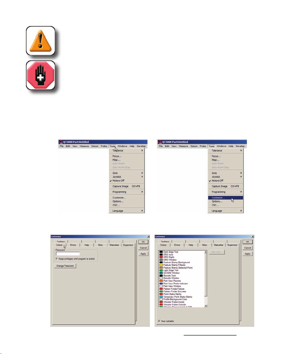
Throughout the Guide, many references are made to screens that must be displayed by clicking the mouse
cursor on a series of menu items and screen tabs. This kind of navigation path is demonstrated in this
example of displaying the
screen, shown in text as: Tools/Customize/Colors.
then clicking the Colors tab...
then clicking the Customize menu item...
displays the
screen
Page 7
Introduction
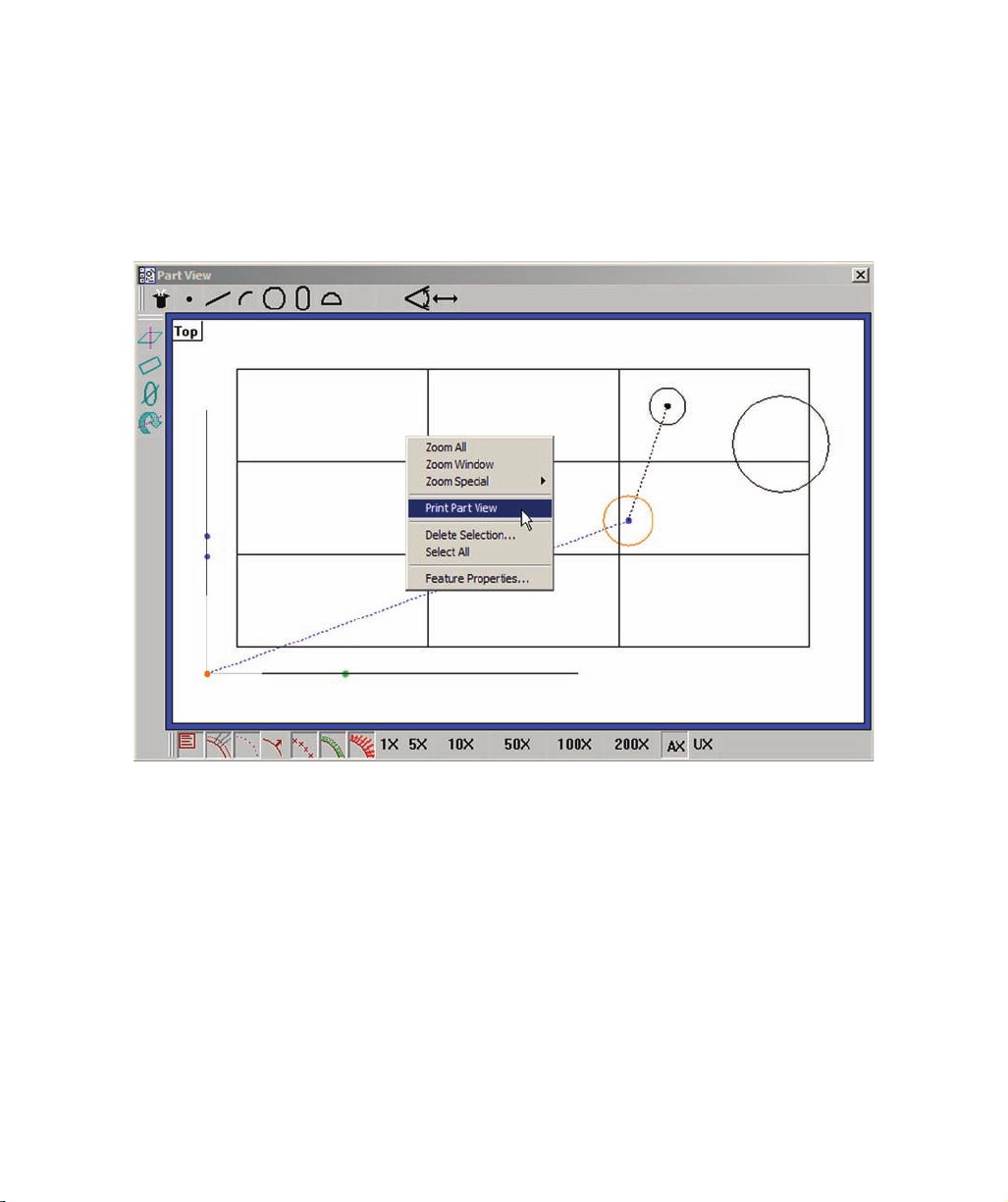
Many commands are displayed by right-clicking the mouse cursor in a window, and then on one or a
series of menu items. This kind of command path is demonstrated in this example of using the Part View
window/Print Part View command to print the part view. The command is shown in text as: Part View
window/Print Part View.
Right-clicking the Part View window, then clicking Print Part View
prints the current part view
Page 8

This Guide contains eleven chapters and three reference appendices. An overview of the contents is pro-
vided below. Experienced users are encouraged to familiarize themselves with the first six chapters before
beginning to use the QC5200. Users that are new to the QC5200 and similar Metronics products should
read the first six chapters carefully and then follow the tutorial in
Chapter 3:
Chapter 3:
Quick Start Demonstartion
Quick Start Demonstartion
before beginning.
Brief introduction to the QC5200 series features and benefits
Comprehensive description of the user interface covering screens, menus, toolbars the statusbar and work-
spaces.
Brief demonstration of using the basic functions of the QC5200 including:
• Organizing the workspace
• Selecting and teaching the probe
• Recording measurement activities as a program
• Measuring & constructing datums
• Measuring features
• Applying tolerances
• Exporting data
• Reporting
• Saving the part and program
Probes
Instructions for calibrating and using video edge detection measurement probes
Instructions for constructing datums and measuring, constructing and creating features.
Instructions for applying tolerances to measurements.
Instructions for organizing, formatting, exporting and printing measurement results.
Descriptions of programming functions and instructions for creating, editing, and debugging programs.
Page 9

Introduction
v
Instructions for calibrating and configuring axis encoders.
Descriptions of setup tools and screens used to configure and customize measurement, programming and
display parameters
Basic troubleshooting guide in the form of a simple table of symptoms, probable causes and recommended
solutions.
Appendi
Appendi
x B:
ASCII Codes
Appendi
x C:
Index
Page 10
vi
The QC5200 is inherently safe, and in proper use few if any potential safety hazards exist. However, many
systems include motorized CNC stages that, as is the case with all motorized equipment, must be treated
with caution to avoid collision and pinch injuries. Also, an entire system often consists of electrical equip-
ment connected by many cables, which must be treated with care to avoid shock and tripping injuries.
Be prepared to depress the emergency off mushroom switch or other similar device
quickly in the event of an emergency when motor axes are active.
on or create a tripping hazard.
The system components are equipped with 3-wire power plugs that include a separate ground
connection, or are grounded through a separate wire. Always connect the power plug to a 3-wire
grounded outlet. The use of 2-wire power plug adapters or any other connection accessories that
remove the third grounded connection create a safety hazard and should not be permitted. If a
3-wire grounded outlet is not available, ask your electrician to provide one. Never disconnect any
separate ground wire.
Do not open the QC5200 enclosure. There are no user-serviceable components or assemblies
inside.
General safety precautions must be followed when configuring, maintaining or operating the system.
Failure to observe these precautions could result in damage to the equipment, or injury to personnel.
It is understood that safety rules within individual companies vary. If a conflict exists between the material
contained in this guide and the rules of a company using this system, the more stringent rules should take
precedence.
Additional safety information is included throughout the remainder of this guide.
WARNINGS - AXIS MOTION
Always stay clear of axis motion paths.
Disconnect axis motor power when motor activities are not required.
WARNINGS - ELECTRICAL
Disconnect the system components from electrical sources before cleaning or
servicing.
Do not allow any power cord or signal cable to be located such that it can be walked
Page 11

Introduction
vii
Disconnect the QC5200 from the power source and seek the assistance of a qualified service
technician if:
• The power cord is frayed or damaged or the power plug is damaged
• Liquid is spilled or splashed onto the enclosure
• The QC5200 has been dropped or the exterior enclosure has been damaged
• The QC5200 exhibits degraded performance or indicates a need for service some other way
Use only a cloth dampened with water and a mild detergent for cleaning the exterior surfaces and display
screens. Never use abrasive cleaners, and never use strong detergents or solvents. Only dampen the cloth,
do not use a cleaning cloth that is dripping wet.
Display resolutions in this guide are examples. User display resolutions are likely to vary according to the
specific application. Metric units of measure are used in examples.
Accuracy & Precision
Measurement accuracy is determined by many factors, such as the resolution of the encoders connected to
axis inputs. Generally, the display resolution of the QC5200 can exceed encoder resolutions. Setting the
display resolution to exceed the encoder resolution does not increase measurement accuracy.
Help is available in this printed Guide, in the electronic version of this Guide accessed from the Help
menu of the QC5200 software, from your Metronics distributor or system provider and directly from
Metronics.
The information contained in this guide should be adequate to customize the measurement, display and
programming aspects of system, and to perform the minimal setup and troubleshooting required beyond
the services provided by your Metronics distributor or system provider. However, in the event that your
Metronics distributor or system provider cannot provide the assistance you need, our support staff is com-
mitted to insuring your positive experience with the QC5200 series of products. To receive technical
support:
Routine issues
e-mail our support staff at: techsupport@metronics.com
Page 12

viii
Telephone your Metronics distributor, or telephone our support staff at: (603) 622.0212
• A description of the equipment attached to the QC5200 computer, including the
manufacturer and model number
• The QC5200 software version number, found on the Help/About QC5000
menu screen
The most recent version of the QC5200 software can be downloaded from the
Product Support
Product Support
section of
our web site at:
http://www.metronics.com
Please carefully read all the instructions and cautions published on our site regarding your software update
before attempting to perform the update.
Additional publications for the QC5200
Additional application or instructional information is sometimes available for download from the Product
http://www.metronics.com
NOTE
If it becomes necessary to contact us directly, be prepared to supply the following
information:
• The QC5200 series serial number
(5-Digit number printed on back label)
Page 13

w
Overview of system features
............................................................................
Introduction
......................................................................................................
7
Windows
...................................................................................................
8
DRO
...................................................................................................
8
Templates
..........................................................................................
8
Results
...............................................................................................
8
Part View
...........................................................................................
8
Live Video
.........................................................................................
8
Menus
.......................................................................................................
9
Toolbars
....................................................................................................
9
...................................................................................................
0
Windows
..........................................................................................................
DRO window
............................................................................................
Part View window
....................................................................................
2
Adding feature data
...........................................................................
3
Live Video window
..................................................................................
5
Results window
.........................................................................................
7
Template Windows
...................................................................................
8
separating templates
.....................................................
8
Adding and
deleting
template content
...............................................
9
Features template
..............................................................................
0
Program template
..............................................................................
2
0
Report template
.................................................................................
0
Tolerance templates
...........................................................................
2
Menus
...............................................................................................................
2
2
Menubar menus
........................................................................................
File menu
...........................................................................................
2
3
Edit menu
...........................................................................................
5
View menu
.........................................................................................
2
9
Measure menu
...................................................................................
3
5
Datum menu
3
5
Probe menu
........................................................................................
3
5
Page 14

Tools menu
........................................................................................
3
6
Windows menu
..................................................................................
3
9
On-screen
menus
Template window menus
...................................................................
4
Template edit menus
..................................
Program edit menus
4
4
Results window menus
...............................................................
6
Part View window menus
..........................................................
5
0
Toolbar menus
............................................................................
5
3
Toolbars
...........................................................................................................
5
5
Changing
toolbar shape
............................................................................
5
6
Docking and
undocking toolbars
..............................................................
5
6
Customizing and
creating toolbars
...........................................................
5
7
...........................................................................................................
5
8
Workspaces
......................................................................................................
5
9
Creating
custom workspaces
....................................................................
5
9
.......................................................................
6
0
Opening custom workspaces
....................................................................
6
0
Demonstration steps
.........................................................................................
6
Organizing the
workspace
................................................................................
6
5
..........................................................................................
6
5
T
eaching the
video
probe
.................................................................................
6
6
Turning
program
recording ON
.......................................................................
6
6
Measuring
part
skew and
datum
...............................................................
6
7
..................................................................................................
6
7
Datum
................................................................................................
6
7
Measuring
features
....................................................................................
6
9
Applying
feature
tolerances
......................................................................
7
0
Adding
data to the
Runs template
.............................................................
7
Exporting data
...........................................................................................
7
Printing
reports
.........................................................................................
7
3
Turning program recording OFF
.....................................................................
7
3
.................................................................................................
7
4
Running the program
.......................................................................................
7
4
4 Probes
Preparing to
use video probes
..........................................................................
7
7
part condition
........................................................................
7
7
video
magnification
..................................................................
7
7
Page 15

Adjusting
light control
..............................................................................
7
7
Associating
lighting with magnifications
.................................................
7
7
Enabling and
disabling light associations
.................................................
7
8
Using video probes
..........................................................................................
7
8
probe type
...............................................................................
7
9
Changing
probe
position
...........................................................................
7
9
Changing
probe
orientation
......................................................................
7
9
Changing
probe
size
.................................................................................
8
0
Changing
scan
direction
...........................................................................
8
0
Changing
edge detection order
.................................................................
8
Enabling and disabling
high accuracy scanning
.......................................
8
2
Firing video probes
...................................................................................
8
3
Dry firing probes
...............................................................................
8
3
Continuous probe firing
.....................................................................
8
3
Loading a
video
chart
...............................................................................
8
4
Video
probe descriptions
.................................................................................
8
5
Crosshair probe
.........................................................................................
8
6
.............................................................................................
8
7
Buffer Probe
..............................................................................................
8
9
Average probe
...........................................................................................
9
Nearest probe
............................................................................................
9
3
Farthest probe
...........................................................................................
9
4
Height probe
.............................................................................................
9
5
Width Probe
..............................................................................................
9
7
Circle Probe
..............................................................................................
9
8
Circles
................................................................................................
9
8
Arcs
....................................................................................................
9
9
Blob Probe
................................................................................................
Worm probe
..............................................................................................
2
New probe
.................................................................................................
5
Pattern Finder probe
.................................................................................
8
Initial setup of the video probe system
............................................................
Adding
magnifications with associated
zooms
.........................................
6
Adding magnifications to the
Probe toolbar
......................................
7
Adding the
highest magnification to the
probe library
......................
8
Adding other magnifications and
associating
Zoom positions
.........
9
Deleting
magnifications
............................................................................
0
Configuring the
highest
magnification
.....................................................
Configuring the
lower
magnifications
......................................................
Calibrating
auto
focus
...............................................................................
2
Calibrating
video
edge recognition (
Teach)
.............................................
Advanced
Edge
Teach
......................................................................
6
Page 16

Calibrating
pixel
resolution
......................................................................
7
Calibrating
offset
......................................................................................
9
Compensating for
camera
skew
................................................................
Configuring
video
probe
data collection parameters
................................
5
Measurement activities
....................................................................................
8
The
measurement workspace
...........................................................................
8
The
measurement process
................................................................................
8
Preparing to use video probes
...................................................................
9
Establishing the
measurement
reference
..................................................
9
Leveling the part (optional)
......................................................................
9
Creating a
skew
alignment
........................................................................
0
Creating a
datum
zero point
......................................................................
Probing a datum zero point
................................................................
Constructing a datum zero point
........................................................
Probing and
measuring features
................................................................
4
Measure Magic
.........................................................................................
4
Probing features
...............................................................................................
Probing specific feature types
...................................................................
6
Points
.................................................................................................
6
Lines
..................................................................................................
7
Arcs
....................................................................................................
8
Circles
................................................................................................
9
...................................................................................................
Distances
............................................................................................
2
Angles
................................................................................................
3
Blobs
..................................................................................................
5
Profile measurements
........................................................................
6
Constructing features
.......................................................................................
Point constructions
....................................................................................
3
Line constructions
.....................................................................................
8
Distance constructions
..............................................................................
5
Circle
constructions
..................................................................................
Arc constructions
......................................................................................
4
Creating features
..............................................................................................
6
Creating a point
.........................................................................................
7
Creating a line
...........................................................................................
7
Creating a distance
....................................................................................
8
Creating a circle
........................................................................................
8
Creating an arc
..........................................................................................
9
Page 17

Applying tolerances to features
.......................................................................
20
3
Tolerance screens
......................................................................................
20
3
Tolerance menu
........................................................................................
20
4
Tolerance toolbar
......................................................................................
20
Display of
tolerance results
......................................................................
20
5
Naming and saving tolerances
..................................................................
20
6
Deleting
Named Tolerances
.....................................................................
20
6
Tolerance types
................................................................................................
20
7
Bidirectional
.............................................................................................
20
7
True position
.............................................................................................
20
8
MMC/LMC (Material condition)
.............................................................
20
9
Runout
.......................................................................................................
21
0
Circularity
.................................................................................................
...............................................................................................
21
Concentricity
.............................................................................................
Profile
.......................................................................................................
21
2
Parallelism
................................................................................................
3
Perpendicularity
........................................................................................
3
Angularity
.................................................................................................
21
3
Angle
.........................................................................................................
Width
........................................................................................................
21
4
Template descriptions
......................................................................................
7
Features template
......................................................................................
21
7
Program template
......................................................................................
8
Runs template
...........................................................................................
9
Runs charts
................................................................................................
22
0
Report template
.........................................................................................
Tolerance templates
..................................................................................
22
3
Opening templates
...........................................................................................
Generating new default templates
....................................................................
22
4
Editing templates
.............................................................................................
5
Adding and
deleting data
..........................................................................
22
5
Adding data
.......................................................................................
5
Adding multiple data fields as a single new column
.........................
6
A
dding multiple data fields as multiple new columns
......................
22
7
Appending data fields to an existing column
....................................
8
Deleting data
......................................................................................
22
9
Deleting
rows
............................................................................................
9
Page 18

Deleting
columns
......................................................................................
23
0
....................................................................
23
0
Aligning column titles and data
................................................................
23
Changing the
order of columns
.................................................................
23
Displaying
horizontal and
vertical
grid line
.............................................
23
Headers and
footers
..........................................................................................
23
2
...........................................................................
23
Editing headers and footers
..............................................................................
23
3
Adding text
...............................................................................................
23
3
Editing text
................................................................................................
23
3
Formatting
text
..........................................................................................
23
4
Including
automatic
text entry
..................................................................
23
5
Prompting the user for alphanumeric information
....................................
23
5
Deleting text
..............................................................................................
23
6
Enabling
text to
speech output
..................................................................
23
6
Adding
graphics from files
.......................................................................
23
6
Drawing
graphics
......................................................................................
23
8
Printing
reports
.................................................................................................
24
Exporting data
..................................................................................................
DDE Output
.....................................................................................................
24
3
Output parameters
.....................................................................................
3
Connection
................................................................................................
24
3
Data
...........................................................................................................
General guidelines
....................................................................................
24
4
8 Programming
Introduction
......................................................................................................
24
9
Creating Programs
...........................................................................................
25
0
Creating the new part
................................................................................
25
program
recording
.......................................................................
25
Performing a
skew and
datum
..................................................................
25
Choosing a
measurement
programming method
......................................
25
Adding tolerances
.....................................................................................
25
4
Reporting results
.......................................................................................
25
Optimizing program steps
.........................................................................
25
4
Adding
special steps to a program
............................................................
25
5
Finalizing
feature properties
.....................................................................
25
7
Finalizing
program properties
...................................................................
25
8
program
recording
.....................................................................
26
..........................................................................................
26
Page 19

Editing Programs
.............................................................................................
26
Part fixturing
.............................................................................................
26
2
Program runtime environment
..................................................................
26
Palletizing multiple parts
..........................................................................
26
2
Editing
initial
program settings
................................................................
26
5
Probe
position indicator
............................................................................
26
6
Template state
...........................................................................................
26
6
Light controls
............................................................................................
26
7
Optical
magnification
...............................................................................
26
7
Probe selection
..........................................................................................
26
7
High accuracy mode
.................................................................................
26
8
Focus lock
.................................................................................................
26
8
Units of measure
.......................................................................................
26
8
Editing
feature properties
.........................................................................
26
9
Hiding features
..........................................................................................
26
9
Displaying
phantom features
....................................................................
26
9
Displaying
guide features
.........................................................................
26
9
note with a feature
..................................................................
27
0
feature name
........................................................................
27
0
Editing
feature
point
filtration
..................................................................
27
0
filtration
error limit
..............................................................
27
filtration
standard deviation range
.......................................
27
Adding
special and CNC program steps
..........................................................
27
Comment
...................................................................................................
27
2
Delay
.........................................................................................................
27
3
Play
sound
.................................................................................................
27
3
Program
image
..........................................................................................
27
4
User message
............................................................................................
27
Enabling or
disabling
run time
graphic displays
......................................
27
5
Enabling or
disabling
full
CNC mode
......................................................
27
5
Enabling or
disabling
power assist mode
.................................................
27
6
Enabling or
disabling
focus lock
..............................................................
27
6
output lines
...................................................................................
27
7
program
steps
...................................................................................
27
8
.........................................................................
27
8
..........................................................................
27
8
Clearing
step selections
............................................................................
28
Editing individual steps
....................................................................................
28
2
Changing the
target position for
probing
..................................................
28
Changing
parents of
construction features
...............................................
28
3
Requiring
user interaction to
complete a measurement
............................
28
Optimizing program steps
.........................................................................
28
5
Page 20

Cutting,
copying,
pasting and
deleting program steps
..............................
28
5
Cutting steps
......................................................................................
28
5
Copying steps
....................................................................................
28
5
Pasting steps
......................................................................................
28
5
Deleting steps
....................................................................................
8
5
Inserting new program steps
.....................................................................
28
6
Debugging programs
........................................................................................
28
7
9 Encoders
TTL encoders
...................................................................................................
28
9
Analog encoders
...............................................................................................
29
0
Joystick setup and
limiting
maximum
axis velocity
........................................
29
0
Axis velocity
.............................................................................................
29
Curvature joystick parameter
....................................................................
29
Axis displacement
.....................................................................................
29
Counter setup
...................................................................................................
29
Limit Switch setup
...........................................................................................
29
2
Calibrating
analog
encoders
.............................................................................
29
3
QC5200
encoder setup
.....................................................................................
29
6
encoder
resolution
..................................................................
29
6
encoder
unit of measure
.........................................................
29
6
encoder
count direction
..........................................................
29
6
encoder
reference marks
.........................................................
29
6
r
eference offsets
.....................................................................
29
7
Tools/Customize menu item screens
...............................................................
29
9
Including a
startup message
......................................................................
30
0
Customizing
colors
...................................................................................
30
on-screen
help tips
..................................................................
30
5
error messages
........................................................................
30
6
status bar information
.............................................................
30
8
Customizing
toolbars
................................................................................
30
9
Tools/Options menu item screens
....................................................................
3
programming parameters
.........................................................
31
4
maximum program executions
.........................................
31
7
Restricting
access to setup screens
...........................................................
31
8
Configuring
measurement parameters
......................................................
32
0
Displaying
parts and
probe position
.........................................................
32
Configuring
joystick and
footswitch buttons
............................................
32
7
display of
resolution,
time and
date
........................................
33
0
Page 21

encoder parameters
.................................................................
33
file names, locations and backups
..........................................
33
2
serial port,
machine zero and
general parameters
........................
33
7
video
probes
.......................................................................
34
0
Tools/CNC menu item screens
.......................................................................
350
joystick
..............................................................................
35
0
QC5200
settings or
appearance have changed. Everything looked
okay the last time you were on the system, now it’s different
....................
35
5
A QC5200
Window is missing from the screen, but is enabled
in the
QC5200 Windows menu
..................................................................
35
5
Measurements are inaccurate or inconsistent
..................................................
35
5
axis
counts in the
wrong direction
.............................................................
35
6
Cannot drag data fields from the Results window into a template
..................
35
7
Changes
to the QC5200 settings, window positions, etc.
are not saved
..........
35
7
The
QC5200 program doesn’t launch, but other Windows programs do
........
35
8
Cannot print from the QC5200 program
..........................................................
35
9
default
template contains
unwanted data or formatting
...............................
36
0
Cannot make changes to the QC5200 settings
.................................................
36
The system seems slow
....................................................................................
36
Cannot see image in the live video window
....................................................
36
3
The auto focus does not work properly
............................................................
36
The measurements finish before I’m ready
.....................................................
36
5
Cannot find captured images
...........................................................................
36
5
Appendix A Import File Formats
Appendix B ASCII Codes
Appendix C Tolerances
Concentricity toleranc
e
Reference Feature
s
Reference feature called for in
MMC or
LMC circle toleranc
e
Projected zon
e
Page 22

Page 23

1 System Overview
The Metronics QC5200 series of metrology instruments is a family of Windows PC-based products for
conducting precision dimensional measurements on 2-D parts. Systems can be supplied with video sys-
tems and measuring microscopes. Systems support manual part positioning and feature measurement
under user control, or CNC part positioning and automated measurement under program control.
All QC5200 systems consist of a Windows-based user interface and a dedicated Metronics
axis
PC card.
All axis cards include input circuitry for reading the axis position. Axis cards in systems capable of CNC
axis motion control also include circuitry for driving
CNC stepper motor or
CNC servo motor amplifiers.
All systems measure
2-D part features in the X–Y plane. Additionally, systems can include a Z-axis input
for height measurements and part leveling and a Q-axis for rotational measurements.
Basic QC5200 for video systems or microscopes with
joystick part positioning
Page 24
Part
features can be measured, constructed from measured features, created from user data, copied from
existing features or imported from .dxf, .igs and other files.
Geometric
tolerances include location,
form, orientation, runout and size. In
addition, tolerances can be applied to
groups of selected features.
Tolerances are context sensitive. For
example, straightness is provided for
lines and circularity is provided for
circles. Tolerances can be displayed
for evaluation and the tolerance criteria
can be edited with a few clicks of the
mouse, as shown in this example of a
form tolerance.
Measured feature
Measured feature
Page 25
1 System Overview
Programs can be created in manual sys-
tems to semi-automate repetitive tasks
and simplify operator interactions, or
in systems that include
CNC control
to automate measurements eliminat-
ing measurement errors and increasing
throughput. Programs can be recorded
automatically as a series of measure-
ments are performed, can be created
to include conditional branching and
messages, can be edited in static or
single-step modes and can be created
from imported
CAD files. The task of
programming is simplified by
programming wizards and a comprehensive program debugging environ-
ment.
Reports can be custom-formatted in a
wide variety of formats to satisfy the
requirements of different audiences
by simply dragging and dropping data
selections into templates.
Templates
can easily be customized. Completed
reports can be archived, printed, ex-
ported or saved for e-mailing.
Exported
data can be sent to CAD applications,
Microsoft
Excel and
Microsoft
Access
for processing.
The user interface conforms to stan-
dard Windows conventions and can
be quickly mastered by experienced
Windows users. Task-specific menus,
icons and toolbars further simplify in-
teractions with QC5200 features and measurement functions. Many aspects of the user interface can be
customized to suit the needs of each user.
Customized arrangements of windows and toolbars can be saved
as unique workspaces to facilitate the most efficient use of the system by different users.
This User’s Guide can be accessed and displayed from the
Help menu, and includes links from all page
references in the Table of Contents and Index to Guide content.
Example of a program recorded automatically as measurements
were performed
Example of a report of feature data
Page 26

4
Page 27

2 User Interface
The QC5200 user interface is a
workspace consisting of
menus,
windows,
toolbars and a
statusbar. The
overall appearance of the user interface can vary greatly and can be customized to satisfy the requirements
and personal preferences of the user. The following pages contain a detailed description of the QC5200
user interface. Here’s what you’ll find in this chapter:
Introduction
...............................................................................................
7
Windows
............................................................................................
8
Menus
.................................................................................................
9
Toolbars
.............................................................................................
9
.............................................................................................
0
Windows
...................................................................................................
DRO window
.....................................................................................
Part View window
..............................................................................
2
Live Video window
............................................................................
5
Results window
..................................................................................
7
Template Windows
............................................................................
8
separating templates
..............................................
8
Adding and
deleting
template content
........................................
9
Features template
........................................................................
2
0
Program template
........................................................................
2
0
Report template
...........................................................................
0
Tolerance templates
....................................................................
2
Menus
........................................................................................................
Menubar menus
..................................................................................
22
File menu
....................................................................................
3
Edit menu
....................................................................................
2
5
View menu
..................................................................................
9
Measure menu
.............................................................................
3
5
Datum menu
................................................................................
3
5
Probe menu
.................................................................................
3
5
Tools menu
.................................................................................
3
6
Windows menu
..................................................................................
3
9
Page 28

On-screen
menus
.......................................................................................
Template window menus
...................................................................
4
Template edit menus
...................................................................
Program edit menus
...........................................................................
4
4
Results window menus
......................................................................
6
Part View window menus
..................................................................
5
0
Live
Video window menus
................................................................
5
Toolbar menus
...................................................................................
5
3
Toolbars
...........................................................................................................
55
Changing
toolbar shape
.............................................................................
5
6
Docking and
undocking toolbars
..............................................................
5
6
Customizing and
creating toolbars
............................................................
5
7
Workspaces
......................................................................................................
5
9
Creating
custom workspaces
.....................................................................
5
9
.......................................................................
6
0
Opening custom workspaces
.....................................................................
6
0
Launching the QC5200 program into a specific workspace
.....................
6
Page 29
2 User Interface
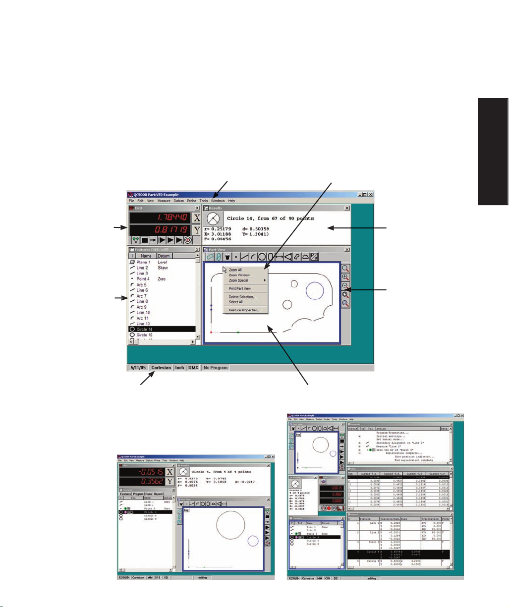
The QC5200
user interface is a workspace consisting of windows, menus, toolbars and a statusbar. The
overall appearance of the user interface can vary greatly and can be customized to satisfy the requirements
and personal preferences of the user. However, the individual elements of every workspace are consistent
in purpose and function, and do not significantly change. Workspace elements include:
• The DRO, Template, Results, Part View and Live Video windows
• Menu bar and on-screen menus
• Toolbars
• Statusbar
The overall appearance of the user interface, or workspace,
can be customized to vary greatly as shown here, but indi-
vidual workspace elements remain essentially unchanged.
DRO window
Results window
Part View window
to the
Part View window
Statusbar
Menubar menus
Introduction
Page 30
Windows
Four window types are used to present numeric, text and graphic information:
• DRO • Templates • Results • Part View • Live Video
DRO
The Digital Readout (DRO) presents numeric position information for
each axis.
Template windows present tabular data describing fea-
tures, programs, runs database contents and tolerance
measurements. The template windows shown here
are stacked. However, each window can be presented
alone.
Results
The Results window contains measurement data related
to a feature selected in a template or in the Part View
window.
Part View
The Part View window contains a graphic display of the
measurement reference frame and measured features.
Live Video
The Part View window contains a real-time display of the
video camera image including the part view at the active
magnification with the active video probe superimposed
over the part image.
Page 31

9
2 User Interface
Menus contain functions that control
file operations,
editing, measurements, displayed information and
overall system configuration and setup. Menus can be accessed by clicking on a menu item in the menubar,
or by right-clicking areas in the workspace.
Toolbars
Toolbars like the examples below contain
icons that provide quick access to functions that are also pro-
vided by menus. Toolbars can be located nearly anywhere within the workspace, and can be docked to
most windows.
Menu accessed from the menubar
Menu accessed by right-clicking a window
Measure toolbar
Program toolbar
Datum toolbar
Separate toolbars
Introduction
Page 32

The statusbar presents information regard-
ing
units of measure, current measure-
ments, programming and other
system
status information across the bottom of
the workspace. The information in the
statusbar changes to support current ac-
tivities.
The statusbar changes to display brief
definitions when the
mouse hovers over a
menu command, as in this example of a
statusbar definition displayed when hover-
ing over the Datum zero menu command.
Statusbar
Page 33

2 User Interface
Windows
Windows present numeric, text and graphic information describing
probe position,
feature measurement
results,
tolerance measurement results,
program content and
measurement database statistics.
Windows include:
• DRO (digital readout) window: Probe position referred to the current measurement reference
(machine zero or part zero)
• Part View window: Graphic display of measured features
• Results window: Measurement result data
• Live Video window: Real-time display of video camera image and active video probe
• Templates: Eight default templates display feature data, program steps,
database and report statistics and tolerance measurement results.
Additional custom templates can be created by the user.
The DRO window shows the current probe position with respect to the zero position
of the current reference frame.
Check the Windows/DRO menu item to display the DRO window, or clear the check
mark to hide it.
The zero location of each axis can be
temporarily changed by clicking the
axis button on the right side of the DRO
window.
Cartesian coordinates are changed to R and Ө for
polar
coordinate
The DRO window can be resized by clicking and dragging the side
or corner of the window.
Axis zero buttons
NOTE
The X and Y axis
systems.
Page 34

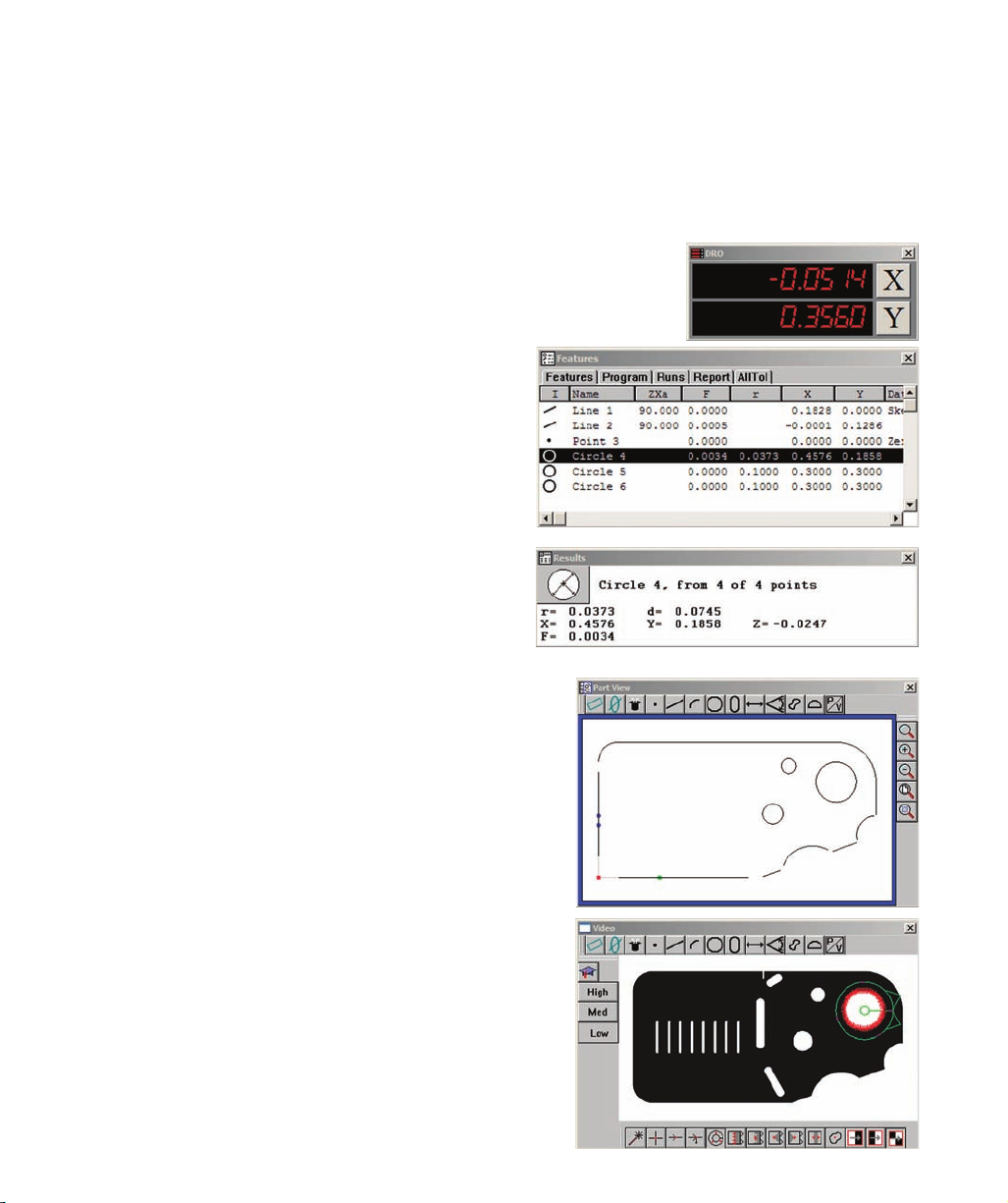
The
Part View window contains a
graphic display of the current measure-
ment
reference frame and all measured
features. This Part View window
shows features of the Metronics quickie
slide and
docked
toolbars. Check the
Windows/Part View
menu item to dis-
play the Part View
window, or clear
the check mark to
hide it.
The current reference frame is shown as X and Y axes and a coordinate zero point. The X-axis is identified
by a single green dot and the Y-axis by two blue dots.
A single part feature or multiple features can be selected by clicking features while pressing the Control
key, or by dragging a marquee across the desired features.
Selecting features by clicking them
Selecting features by dragging a marquee
Axis identifiers
Page 35

2 User Interface
When the marquee is dragged across fea-
tures from left to right, all features touched
by the marquee are selected.
When the marquee is dragged across
features from right to left, only features
completely enclosed by the marquee are
selected.
Adding feature data
Feature data can be added to the Part View window by clicking and dragging the desired data for a selected
feature from the Results window to the Part View window.
Dragging the marquee from left to right selects all features
touched by the marguee
Dragging the marquee from right to left selects only features
completely enclosed by the marguee
Data for the selected feature is clicked and dragged...
into the Part View window
clicked and dragged to the desired position
Page 36

Zoom and other Part View window functions can be accessed by clicking the Windows/View menu or by
right-clicking in the window. These functions are described in detail later in the Menus section of this
chapter.
The Part View window can be resized by click-
ing and dragging a corner of the window.
Accessing functions from the Menubar
Accessing functions from the on-screen menu
Page 37

2 User Interface
The Live Video window displays a real-
time image from the
video camera. The
active video probe is shown superimposed
over the image.
Check the Windows/
Live Video menu
item to display the
Live Video window,
or clear the check
mark to hide it.
The image size is controlled by the
Probe/Magnification menu and the Probe
toolbar.
Click the desired Probe/Magnification
menu item or
Probe toolbar button to
change the
camera
magnification.
or Probe toolbar to change the camera magnification
Page 38

The display of live video typically appears in its own
screen space when two monitors are used.
However, the display can be toggled between the Live Video window and the Part View window to con-
serve screen space when only a
single
monitor is used. Position the Live Video window directly over
the Part View window, matching the window sizes, then click the
P/V toolbar button
to toggle
between the two windows.
Page 39

2 User Interface
The
Results window contains measure-
ment data for the selected feature.
Check the Windows/Results menu item
to display the Results window, or clear
the check mark to hide it.
All basic
feature data is displayed for
the current coordinate system. The
information changes to reflect the new
coordinate system when the measure-
ment coordinate system is changed by
the user.
Results window functions can be accessed by right-clicking the window. These functions are described in
detail later in the Menus section of this chapter.
The size and shape of the Results window can be changed by clicking and
dragging a corner, but the content’s text format remains unchanged when this
method is used.
To change the text formatting of the Results window, right-click the title bar
of the Results window to display the Results window menu, then highlight the
desired Results window text format and release the mouse. The new format
will be displayed.
Simply changing the over-
all shape doesn’t change
the text formatting
changed from the Results
window menu
Page 40

Template Windows
Template Windows present tabular data and information
describing
features,
programs, runs
database content and
tolerance measurements. Template Windows can ap-
pear separately, or can be tabbed and stacked to
save screen space.
Check the desired template title in the recent template portion of the Windows menu
to display the template, or clear the check mark to hide it.
If the desired template is not shown in the list of recent templates, click the Windows/
Open Template menu item to select and open it, or right-click the Template window
and open a new template from the on-screen menu. Menubar and on-screen menu
functions are described in detail later in the Menus section of this chapter.
separating templates
and dropping one template onto
another.
Unstack templates that you wish
to appear separately by clicking
and dragging the title tab of one
template away from the stack.
windows presented separately
windows tabbed and stacked
onto the template stack
Page 41

2 User Interface
Eight default templates are included in the QC5200 system. These default templates include:
• Features
• Program
• Report
• Runs
• Tolerance (four tolerance templates are available)
Adding and
Each template contains default columns for displaying information appropriate for the template type.
However, columns can be deleted or added to suit the needs of the user. Columns are deleted using the on-
screen template menu described later in the Menus section of this chapter. Columns are added by dragging
and dropping data fields from the Results window as shown in the example below.
Template scrollbars provide access to information that extends
beyond the fixed boundaries of the template window.
Diameter is clicked in the Results
window and dragged...
from the Results window to the
Features template...
to create a diameter column in the
Features template
Scrollbars
NOTE
When the Results window is locked in the Tools/Options/Locks setup screen, data
fields cannot be dragged and dropped from the Results window into templates.
Page 42

Features template
The
Features template displays
dimensional
data for all measured, created or constructed
features. Default columns include the
feature icon, tolerance, feature name and
datum.
Use of the Features template is described in
detail in
Chapter 5: Measuring
Chapter 5: Measuring
Program template
The
Program template displays a list of
pro-
gram steps with information that includes
program status, tolerances, current step, ac-
tions to be performed and the program data
such as loop executions completed.
Use of the program template is described in
detail in
Chapter 8: Programming
Chapter 8: Programming
Report template
The
Report template displays a
tabular summary of
feature data
intended as the basis of printed re-
ports of measurement results.
Use of the report template is de-
scribed in detail in
Chapter 7: Reporting and Tem-
Chapter 7: Reporting and Tem-
plates
plates
Page 43

2 User Interface
Tolerance templates display tabular summaries of tolerance measurement results.
Four default Tolerance templates are available. Each template contains a feature icon, tolerance flag (pass-
fail), tolerance symbol, feature name, nominal value, actual value and deviation. Tolerance templates
include:
AllTol: Complete tolerance information for all features
•
EuroTol: Cartesian +/- tolerance values formatted for European users
TolRep: Complete tolerance information for only toleranced features
•
QDAS: Report of feature data formatted for European users
Use of Tolerance templates is described in detail in
Chapter 7: Database, Reporting and Templates
Chapter 7: Database, Reporting and Templates
Page 44

Menus can be displayed by clicking a menu title in the menubar, or by right-clicking certain items within
the workspace area.
Most menus accessed by right-clicking in the workspace area are also available in the menubar.
The menubar includes the following categories of menus:
File: Typical Windows file and print functions
•
Edit: Functions for editing features and programs
View: Workspace viewing alternatives
•
Measure: Feature measurement selections
•
Datum: Reference frame creation
Probe: Measurement probe selection and adjustment
•
Tools: Tolerance, CNC, programming, setup and language functions
Windows: Window selection and template functions
•
Help: User guide, backup and diagnostic utilities
A menu is displayed by clicking a menubar title
Another menu is displayed by right-clicking an item
within the workspace area
Page 45

2 User Interface
File menu
Most file menu functions are identical to those found in other Windows
applications and are shown below:
New
Opens a new part or initiates a new run of the current program.
Chapter 10: Supervisor Setup
Chapter 10: Supervisor Setup
, Tools/Options/Files
Open
Displays the Open Part file dialog box to select and
open an existing part.
Save
current filename. If the part is new and has no cur-
rent filename, the Save Part As file dialog box will
be displayed and a new filename will be required.
Save As
Displays the Save Part As file dialog box. The
part file and part program are then saved using a
filename of the user’s choice.
Import
Imports part files in one of many standard formats.
Refer to
Appendix A:
Appendix A:
Import
Import
File Formats
for
details.
NOTE
The QC5200 can be configured to automatically save
part changes when a new program run is initiated. Refer
to the
screen.
Page 46

Export
Exports highlighted feature data in one of many
standard file formats to a location of, and using a
file name of the user’s choice.
DDE output
Exports highlighted feature data to an application
of the user’s choice using Microsoft’s Direct Data
Exchange protocol.
Page setup
and configuring a printer.
Print preview
Displays a dialog box for selecting the source ma-
terial to print and the number of copies to be printed, then displays a preview of the printer output.
Print
Displays a dialog box for selecting the source material to print and the number of copies to be printed, then
prints the material.
Delete current part
Deletes the current part file and all associated files. Users are asked to confirm the delete request.
Exit
Closes the QC5200 application. Users are given the opportunity to save the part file before closing.
Chapter 10: Supervisor Setup
Chapter 10: Supervisor Setup
,
NOTE
The QC5200 can be configured to automatically save changes to part and template
files upon exiting the application. Refer to the
Tools/Options/Files screen.
Page 47

2 User Interface
Edit menu
The first seven items of the Edit menu provide standard Windows editing functions
for cutting, copying, pasting, deleting and selecting elements in one of the QC5200
templates.
In the example shown below, Circles 4, 5 and 6 are selected and then copied from the
Features template and pasted into a Notepad document.
NOTE
The use of these standard editing functions is shown throughout the remainder of this
guide as part of the many instructions and examples that follow.
Page 48

Find Features
Features listed in the Features, Report and Tolerance templates can be found and
highlighted (selected) by the system. This is useful when selecting features with
similar names from long lists containing many different feature types.
Clicking the Find Features menu item displays the Find Feature dialog box.
Feature names are entered directly into the Name field.
Checking the Add to Current Selection box adds the new
feature(s) to any existing selections. Clearing the box
replaces any existing selections with the new features.
The Find Feature function can be limited to features that
passed or failed tolerance tests by checking the Passed
or Failed Tolerances boxes, can find all features of the
specified name by clearing both boxes, or can find only
toleranced features of the specified name by checking both boxes.
Clicking the Advanced but-
ton displays the advanced
Find Feature dialog box.
Advanced search criteria
include characteristics
listed in the Item, Condi-
tion and Value drop-down
lists.
A wide variety of
search
criteria can be specified
and then included in, or
excluded from the search
using drop-down lists and
tool buttons on the advance
Find Feature dialog box.
Page 49

2 User Interface
Change feature
Features are measured by selecting feature types from the Measure menu or Measure toolbar and then
probing part features. When a specific feature type is selected prior to probing, the feature data is assigned
the specified feature type and cannot be changed. However, when Measure Magic is selected prior to
probing, the feature type can be changed using the Change Feature menu item.
The Change Feature function is useful when one set of fea-
ture data describes different feature types. In this example,
a shallow arc was interpreted as a line with marginal form,
and is changed from a line to an arc in the Features list.
Feature properties
The Feature Properties dialog box
contains tools for specifying feature
properties that include:
•
Name
The feature name
•
Display/Hidden
Hides or shows the feature in
the Part View window
Display/
Phantom
Displays the feature as a dashed
line or a solid line
Display/Guide
Displays the feature as a guide,
outlined in the Part View
window during program
executions
•
Display/Show Note
Displays a
note over the feature
in the Part View window
Display/Show Name
Displays the feature’s name in the Part View window
•
Point Filtration/
Filtered
Displays only data points within the specified sigma factor, and with errors lower in value than the
specified Quantization limit
Page 50

Chapter 10: Supervisor Setup
Chapter 10: Supervisor Setup
for additional details requiring display and
The
Type field displays the feature type and cannot be changed.
The
Run field displays the program run number used to record the feature data in the runs database.
NOTE
Refer to
point filtration properties.
Page 51

2 User Interface
The
View menu includes functions for:
Zooming in or out to show Part View, Feature stamp and Profile
window contents at different magnifications
•
Panning the contents of the Part View, Feature stamp and Profile
window
•
Profile window
•
• Displaying the Toolbar selection dialog box
• Specifying
English or
metric
units of measure
• Specifying
Cartesian or
polar coordinate systems
• Opening, saving or specifying workspaces
Zoom all
Click Zoom All to automatically fit all measured features in the Part View
window.
automatically zooms to fit all features into the
Part View window
Page 52

Zoom Window
Click Zoom Window to display the magnifying glass cursor. Click and drag
the cursor to select the portion of the Part View window to be magnified and
fit into the Part View window.
Zoom Special
Click Zoom Special to zoom in, Zoom out or zoom to fit a se-
lected feature or collection of features into the Part View win-
dow.
to select an area to fit into the Part View window
increases the magnification without changing position
Page 53

2 User Interface
Zoom Out...
decreases the magnification without changing position
Selecting a feature or features and clicking Zoom
Selected...
fits the selected feature or features into the Part View
window
Page 54

Pan
Click Pan to display the
hand
cursor. Click and drag the hand cursor in the
desired direction to reposition the image displayed in the Part View window.
Show
position indicator
The position of the probe can be shown in the Part View window as a large dot
by checking the Show Position Indicator menu item. Clicking the menu item
toggles a check mark on and off.
cursor...
moves the contents of the Part View window
Indicator on...
displays the probe position as a dot in the Part View
window
Position indicator
Page 55

2 User Interface
Show
reference frame indicator
The
X-Y reference frame can be shown in the Part View window as large dots
on the X and Y axes by checking the Show Reference Frame Indicator menu
item. The X-axis is indicated by a single dot. The Y-axis is indicated by two
dots. Clicking the menu item toggles the check mark on and off.
Units
Measurements can be shown in
English or
metric units, and in
Cartesian or
polar coordinates by checking the desired Units menu
item selections. Clicking a menu item toggles the check mark on
or off.
Checking Units selections displays the desired units of measure
and coordinate system in the Results window and in all templates.
The current units of measure and coordinate system are also dis-
played in the Status bar.
Frame Indicator on...
displays the X-Y reference frame indicators as dots on
axes in the Part View window
X indicator dot
Page 56

Workspaces
Click the Workspaces menu item to open or save a work-
space. Recently used workspaces are listed in the bottom
section of the Workspaces drop-down menu.
Page 57

2 User Interface
Measure menu
The measure menu provides access to the QC5200
measurement func-
tions. Detailed descriptions of the measurement functions are con-
tained in
Chapter 5: Measuring
Chapter 5: Measuring
Datum menu
The datum menu provides access to the tools required to establish a
measurement
reference frame. Measurement reference frame con-
struction is discussed in detail in
Chapter 5: Measuring
Chapter 5: Measuring
Probe menu
The Probe menu provides access to tools for:
• Selecting a
video probe
• Displaying the light control
• Associating light settings with the current camera
magnification
• Enabling or disabling light w/mag function
• Calibrating the video edge detection
• Displaying the Probe Library functions
• Selecting
camera
magnification levels
The contents of the Probe menu are described in detail in
Chapter 4: Probes
Chapter 4: Probes
Page 58

The Tools menu provides access to tools for:
• Conducting
tolerance measurements
• Filtering the video camera image for improved edge detection
• Moving the stage to the Worm probe start or stop position
• Controlling
CNC functions
• Capturing a bitmap of the current camera image
Programming automated and semiautomatic measurements
• Configuring
supervisor
setup parameters for the QC5200 system
• Specifying a
language for screen displays and file output
Tolerance menu items
The menu items available for per-
forming tolerance measurements
change in support of the feature
selected in the Part View window
or active template.
Tolerance menu items are
described in detail in
Chapter 6: Tolerancing
Chapter 6: Tolerancing
Filter functions
Clicking Filter launches the image processing functions that include tools for clean-
ing and optimizing the camera image to improve video edge detection. The filter
functions are described in detail in
Chapter 4: Probes
Chapter 4: Probes
Goto Worm functions
Clicking Goto Worm or Goto Stop Worm sends the stage to
the beginning or end of the Worm video probe path. The Goto
Worm functions are described in detail in
Chapter 4: Probes
Chapter 4: Probes
Page 59

2 User Interface
CNC control functions
CNC functions control the stage position,
joystick behavior and CNC
motors.
Goto
The Goto functions control the CNC stage. Clicking
Goto Position
moves the CNC stage to a specified coordinate. Clicking
Goto Click or
Goto Selected Feature moves the stage to a mouse location clicked on
the Part View window or to the center of a selected feature. The Goto
functions can be used anytime, but are typically used during a program-
ming session or during program execution. Detailed descriptions of the
Goto functions are contained in
Chapter 8: Programming
Chapter 8: Programming
Joystick
The
Joystick functions control the resolution of joystick motion, limit motion to a single axis
and enable/disable automatic
part following when part alignment has been performed.
These joystick functions are not included in part programs, but are typically used by the operator during
programming sessions or program execution. Detailed descriptions of the joystick functions are contained
in
Chapter 8: Programming
Chapter 8: Programming
Motors off
Checking the Motors Off menu item disables
CNC motor operation. Clicking the Motors Off menu item
toggles the check mark on and off.
Capture Image
Clicking Capture Image creates a bitmap (bmp) file of the current camera image and
stores the file in the QC5000\Parts folder using a name that includes time and date
information.
The Capture Image function can also be launched by pressing the Control and F8
computer keyboard keys simultaneously.
functions
Page 60

Programming functions
Programming functions are used during programming sessions, pro-
gram execution, for program editing and for program troubleshoot-
ing. The programming functions are described in detail in
Chapter 8: Programming
Chapter 8: Programming
Setup functions
The Customize, Options and
CNC menu items provide access
to the supervisor setup functions
that are used to configure most
operating characteristics of the
QC5200 system. The supervisor
setup functions are explained in
detail in
Chapter 10: Supervisor
Chapter 10: Supervisor
setup
setup
technical support group. Contact information is provided in
Chapter 11: Problem solving
Chapter 11: Problem solving
.
Language
A language for the display of information on the screen, in exported
files and on printed reports is specified by clicking the Language
menu item and then clicking the desired language.
Setup
functions
CAUTION
Changing setup functions may significantly impact the accuracy and reliability of
your QC5200 system. These setup functions should be used only by technically quali-
fied supervisors, OEMs and Metronics distributors. If you have questions regarding
the setup of your system, please contact your Metronics distributor or the Metronics
Page 61

2 User Interface
The Windows menu contains selections for:
• Displaying or hiding the
DRO (Digital readout) window
• Displaying or hiding the
Part View window
• Displaying or hiding the
Results window
• Displaying or hiding the
Live Video window
•
Creating a
new
template
Opening an existing template
•
• Saving the current template with a new name
• Displaying recently used templates
Displaying and
hiding
windows
Check a window name to display the window in the QC5200
workspace. Clear the check mark to hide it.
Creating a new template
Click the New Template menu item to create a new template. The New Template
Name dialog box will be displayed.
Enter the desired name into
the File Name field, then click
dialog box will be dis-
played.
Click the desired template
type, then click the Use
Defaults box to apply all
the selected template’s
defaults to the new tem-
plate, or clear the box to
create a blank template.
window to
display it
DRO window
Part View window
Results window
Live Video window
Page 62

40
Opening an existing template
Click the Open Template
menu item to open an existing
template. The Open Feature
Template dialog box will be
displayed.
click Open.
Saving templates
Templates that have been modified can be saved using
the existing file name or a new filename.
Save with an existing file name
Click the Save Templates menu item. All current templates will be saved using
their existing filenames.
Save with a new filename
Click the Save Template As
menu item. The Save Feature
Template As dialog box will be
displayed.
Only the active template will
be saved with a new filename.
Enter the desired filename and click Save.
Displaying recently used templates
Recently used templates are displayed in the lower portion of the Windows menu.
Check a template to display it, or clear the check mark to hide it.
name to display it
Page 63

41
2 User Interface
On-screen menus are displayed by right-clicking different areas of the screen within the QC5200 work-
space. The following categories of on-screen menus are available:
• Template window menus
• Results window menus
• Part View window menus
• Live Video window menus
• Toolbar menus
Template window menus consist of template edit and program edit menus.
Template edit menus provide access to standard Windows editing functions, feature editing functions,
template functions and chart functions. Template edit menus are displayed by right-clicking a column
heading of any template.
A slightly simpler version of the template edit menu can be displayed by right-clicking the title bar of any
template except the programming template. This simpler edit menu does not include the Column Proper-
ties and Delete Column functions.
Page 64

42
Common editing functions
The common
editing functions include:
•
Feature Properties
Cut
•
Copy
Delete Selection
•
•
Change Feature
These first 6 common editing functions are identical to menubar items described earlier in this chapter and
are included again in on-screen menus as a convenience for the user.
Print selection
A feature or collection of features can be selected using standard Windows methods. Selected features are
highlighted, and can be printed by clicking the Print Selection menu item.
prints the selected feature data
Page 65

43
2 User Interface
Template properties
Clicking the Template Properties menu item provides access to tools for specifying parameters for the
current template. The Properties tool are slightly different for each template type.
The template tools are discussed in detail in
Chapter 7: Reporting and Templates
Chapter 7: Reporting and Templates
Template file operations
Template file operations include:
•
New Template
Open Template
•
These menu items are identical to menubar items described earlier
in this chapter and are also included in on-screen menus as a con-
venience for the user.
displays tools for specifying template parameters
operations
Page 66

44
Charts
Clicking the Charts menu item provides access to charts charac-
terizing the statistical performance of feature data collected by
a series of program executions (runs).
The Charts function is discussed in detail in
Chapter 7: Reporting and Templates
Chapter 7: Reporting and Templates
Program edit menus
Program edit menus provide access to standard Windows edit-
ing and printing functions, template properties tools, and a wide
variety of programming functions. Program edit menus are
displayed by right-clicking the title bar or a content line of the
Program template.
Right-click the title bar...
or contents of the program template
Page 67

45
2 User Interface
Common editing, printing and template functions
The common editing, printing and template functions include:
•
Cut
Copy
•
Paste
Paste Special
•
Delete Selection
•
•
DDE Output
Print Selection
These menu items are identical to menubar items described earlier in this chapter
or are standard Windows functions. They are included in on-screen menus as a
convenience for the user
Programming functions
Programming functions include:
Copy and mirror
•
Pause Mode
•
Record/Edit Mode
CNC Mode Steps
•
Editing Steps
•
Flow Control Steps
Programming Wizards
•
The programming functions are described in detail in
Chapter 8: Programming
Chapter 8: Programming
Page 68

46
Results window menus
The Results window menus provide access to tools for:
• Specifying a fit algorithm for the probed data points
• Redefining the feature type (when Measure Magic is used)
• Specifying tolerance parameters
• Exporting feature data using the Microsoft DDE protocol
• Deleting the selected feature
• Specifying feature display and filtration properties
• Formatting the display of the Results window
Results window menus are displayed
by selecting a feature in the Features
template or on the Part View window,
and then right-clicking anywhere in the
Results window.
Specifying a
fit
algorithm
When more than the minimum required number of points are probed to capture a
feature, alternative algorithms can be specified to fit the data.
Click the desired fitting algorithm to re-fit the probed data points.
NOTE
The contents of the Results window menu changes to support the selected feature type.
For example, the menu for a line feature is different than the menu for a circle fea-
ture.
Page 69

47
2 User Interface
Redefining the
feature type
When
Measure Magic is used to capture feature data and the probed data could fit more than one feature
type, the wrong feature might be displayed in the Feature template and Results windows.
In this example, a shallow arc is initially clas-
sified as a line with poor form (0.0113).
Clicking the Arc feature alternative changes
the feature classification to Arc, with a better
form (0.0038).
Change the current feature type by clicking
the desired feature type in the Results window
menu.
Change
name
Feature names can be changed to make feature names consistent with drawing nomenclature or to simplify
reporting.
Click the Change Name menu
item to display the Change Fea-
ture Name dialog box, then en-
ter the desired name and click
OK.
The original feature (type)
name will be retained by the
system, but the new name will
be shown in the Part View win-
dow, in templates, in reports
and in exported data files.
NOTE
Feature alternatives are not
provided when a specific
measure function is used in
place of Measure Magic.
Page 70

48
Tolerance
The
Tolerance menu item provides access to tools for specifying
tolerance parameters for the current feature.
The tolerance menu item functions are described in detail in
Chapter 6: Tolerancing
Chapter 6: Tolerancing
DDE output
Click the DDE Output menu item to export data for the current
feature to an application using Microsoft’s DDE protocol.
Delete selection
Click the Delete Selection menu item to delete the current feature.
Feature properties
The Feature Properties functions are identical to menubar items described earlier in this chapter and are
included in on-screen menus as a convenience for the user.
Format
The Format menu item provides access to tools for:
• Specifying a
narrow or
wide window
Left or
right justifying label text
• Specifying
text
font size
• Editing Results window fields
Narrow Format/Wide Format
Click the Narrow Format or Wide Format menu item to specify
the desired Results window aspect ratio.
Narrow format
Page 71

49
2 User Interface
Left Justify/
Right Justify labels
Click the Left Justify or Right Justify menu item to specify the
desired Results window label text justification.
Font size
Click the Font Size menu item to choose a specific point
size for all text in the Results window, or click Auto Size to
allow the QC5200 to determine the optimum font size.
Fields
The Fields menu item provides access to advanced formula
and field editing tools that are reserved for qualified special
application developers.
Left justified
Right justified
Page 72

Part View window menus
The Part View window menus provide access to tools for:
• Zooming in or out to show Part View window contents at different magnifications
• Printing the contents of the Part View window
• Deleting selected features
• Selecting all features
• Specifying feature properties
Zoom functions
The
Zoom All,
Zoom Window and
Zoom Special functions are identical to menubar
items described earlier in this chapter and are included in on-screen menus as a con-
venience for the user.
Print part View
Click Print Part View to display the Enter Report Header Data dialog box.
Enter the desired header information
and click OK. The contents of the Part
View window will be printed in the
format determined by the current Page
Delete selection
Click the Delete Selection menu item
to remove the highlighted feature(s).
Select all
Click Select All to select all features.
Feature properties
The Feature Properties functions are
identical to menubar items described
earlier this chapter and are included in
on-screen menus as a convenience for
the user.
Part View printout
Page 73

2 User Interface
Live
The
Live Video window menus provide access to tools for:
• Firing the current video probe
• Selecting the New VED probe
• Selecting a VED probe
• Teaching (calibrating) video edge detection
• Filtering camera images to improve video edge recognition
• Sending the stage to the beginning (Goto Worm) or the end (Goto Worm Stop) of the
worm probe travel
• Capturing a bitmap of the current camera image
• Automatically finishing a feature measurement (Auto Finish) after a video tool is fired
• Selecting the High Accuracy mode for data acquisition
• Selecting the Continuous Fire mode for probe positioning
• Entering or removing data points and completing or cancelling a measurement
Most Live Video window menu items pertain to video probe calibration or use in mea-
surements and are described in detail in
Chapter 4: Probes
Chapter 4: Probes
and
Chapter 5: Measuring
Chapter 5: Measuring
Dry
fire probe
During a probe setup process, when Measure Magic is not used, click Dry Fire Probe
to indicate data points that will be collected during actual measurements. During a
measurement session, when Measure Magic is used, clicking Dry Fire Probe collects
feature data.
New VED Probe
Click New VED Probe to select the New VED Probe for a measure-
ment.
VED Probes
Click VED Probes to select a probe from the list of VED probes. Click
Load Video Chart to import a dxf overlay file as a basis of qualitative
visual part inspections.
Teach VED Edge
Click Teach VED Edge to calibrate VED edge detection. Follow in-
structions presented on the screen. Details are provided in
Chapter 4: Probes
Chapter 4: Probes
Filter
Click Filter to launch an image processing utility that can be used to optimize the camera image for video
edge detection. Follow instructions presented on the screen. Details are provided in
Chapter 4: Probes
Chapter 4: Probes
Page 74

Goto Worm/
Goto Worm Stop
Click Goto Worm or Goto Worm Stop to send the stage to the beginning or end of the
Worm probe path during a measurement session using the Worm probe. Details are
provided in
Chapter 4: Probes
Chapter 4: Probes
Capture Image
Click Capture Image to capture the current camera image as a bmp file in the QC5000\
Parts folder. The file will be given a name that includes the time and date of the capture
operation.
Auto Finish
Click auto Finish to toggle the Auto Finish function on or off. When Auto Finish is enabled, a feature
measurement will be completed when a video probe is fired.
Other/
High Accuracy
Click High Accuracy to toggle the High Accuracy measurement mode on
or off. When the High Accuracy mode is enabled, three sets of data will be
collected and averaged when a probe is fired. The average will be returned
as feature data.
Other/
Continuous
Click Continuous to continuously fire the active video probe for probe per-
formance evaluations. Data will not be collected until the probe is fired by
the operator, but data points will be displayed at the probe continuously.
The Live Video window menu changes slightly during a measurement to the include
measurement functions Enter Pt, Remove Last, OK and Cancel.
Enter Pt
Click Enter Pt to acquire a data point or data points by firing the current probe.
Remove Last
Click Remove Last to remove the last acquired point from the current collection of data
points.
OK
Click OK to complete the current measurement and send acquired data to the Feature list.
Cancel
Click Cancel to cancel the current feature measurement.
Page 75

2 User Interface
Toolbar menus
Toolbar menus are identical for all toolbars and are displayed by right-
clicking on a toolbar.
Toolbar menus provide access to functions for:
• Displaying or hiding toolbars
• Customizing toolbar content
• Changing toolbar appearance
Displaying or
hiding toolbars
Check a toolbar title to display the toolbar. Clicking a title toggles the
check mark on or off.
Click the
Customize menu item to display the Customize Toolbars
dialog box. The customize toolbar functions are described in detail in
Chapter
Chapter
10: Supervisor Setup
10: Supervisor Setup
Display
Clicking the
Display menu item provides access to tools for changing
the toolbar icon size and toolbar title.
Toolbar
icon size
Click Normal, Large or Huge to specify the toolbar icon size as pre-
ferred.
Normal icon size
Large icon size
Huge icon size
Page 76

Change
toolbar title
Click the Change Toolbar Title menu item to display the Change Toolbar Title dia-
log box.
Enter the desired toolbar title and click OK. The new title
will be displayed immediately in the toolbar.
Page 77

2 User Interface
Toolbars
Toolbars contain
icon
buttons that provide quick access to commonly used functions. Nearly all toolbar
functions are also available in menubar or in on-screen menus. Clicking a toolbar button initiates the
function.
Click the View/Toolbars
menu item to display the
Toolbars dialog box. High-
light the desired toolbar title,
and then click Show to dis-
play it, or click Hide to hide
it.
Toolbars can also be dis-
played or hidden by right-
clicking the toolbar. The list
of available toolbars will be
displayed. Check a toolbar
title to display it, or clear the
toolbar check mark to hide
it. Clicking the toolbar title
toggles the check mark on
and off.
Toolbar icon functions are shown in
tool tips when the mouse cursor hovers
over an icon. The tool tip function is enabled in the Tools/Customize/Help
screen.
Icon button
Program toolbar
Page 78

toolbar shape
Toolbars can be displayed as horizontal or vertical bars, or as blocks. The shape of a toolbar can be
changed by clicking and dragging a corner.
Toolbars can be docked to the DRO, Results window and Part View window
to conserve screen space and organize the workspace to suit the preferences of
individual users.
To dock a toolbar, click and drag the desired toolbar to the edge of the target
window, and then release the mouse. An edge of the toolbar should slightly
overlap the inner perimeter of the target
window as shown here.
When a toolbar is docked, its
title bar is replaced with two
parallel lines.
overlaps the perimeter of
the Part View window
docked to the Part View
window
its title bar is replaced with
two parallel lines
Parallel lines
datum toolbar
has title bar
Docked datum
toolbar has
parallel lines
Page 79

2 User Interface
To undock a toolbar, click on the toolbar’s parallel lines.
The toolbar will separate from its docked position. Then
click and drag the toolbar to a new location.
creating
toolbars
Toolbars can be customized by the user to better support
specific application requirements. New custom toolbars
can be created that include any collection of function icons.
Toolbar customizing and creation is described in detail in
Chapter 10: Supervisor Setup
Chapter 10: Supervisor Setup
Page 80

The statusbar presents information regarding measurement, program and other QC5200 status. Status
information fields can include:
•
Date
Coordinate system (Cartesian or polar)
•
Units of measure (English or metric)
• Current
probe
magnification
•
Angular display units (degrees, minutes, seconds or digital degrees)
Error correction enabled
Program status
•
Fine position enabled
Temperature compensation status
Click the Tools/Customize/Statusbar menu item
to display the Statusbar dialog box. Highlight the
desired status information, and then click Show to
display it or click Hide to hide it.
The Statusbar is also used to display descriptions
of functions. When the
mouse cursor hovers over
a menu item, the Statusbar
changes to provide a brief
description of the menu
item function.
The statusbar can be displayed from left to right, or from right to left. Check or clear the Display items...
box of the Tools/Customize/Statusbar screen as desired.
hovers over a menu
item...
the Statusbar displays
a description of the
function
Page 81

2 User Interface
Workspaces
QC5200 workspaces contain all elements of the user interface organized to satisfy the needs and prefer-
ences of individual users.
custom workspaces
Custom workspaces can be created by
using the tools discussed earlier in this
chapter to customize the shapes, content
and locations of Windows, templates
and toolbars. The two screens shown
on this page contain the same part data
but have customized to show it differ-
ently, illustrating the flexibility of custom
workspaces.
DRO window
Results window
Part View window
to the
Part View window
Statusbar
Menubar menus
Page 82

Workspaces are stored in the Workspaces folder of the QC5000 directory using a .5ws file extension. To
save a workspace, click the View/Workspaces menu item and then click Save Workspace as. The Save
Workspaces as file dialog box will be displayed. Enter the desired name and click Save.
When saved, the workspace name will be shown on the template tabs and in the View/Workspaces list of
available workspaces.
Custom workspaces can be opened to restore the user
interface to an organization of Windows, toolbars and
templates developed at an earlier time. To open a
custom workspace, click the View/Workspaces menu
item to display the list of available workspaces, and
then click the desired workspace name.
Page 83

2 User Interface
When multiple operators use the same QC5200 system and prefer different workspace layouts, it is conve-
nient to provide each operator with a unique desktop shortcut that launches the QC5200 program directly
into a specified workspace.
To create a custom desktop shortcut:
The Properties dialog box will be displayed.
2 Append the following information to the command line in the Target data
field:
space, path to specific workspace file in the workspaces folder
for example, to launch directly into a workspace previously saved as
Jeff,
the
revised command line would be:
C:\QC5000\QC5000.exe C:\QC5000\workspaces\Jeff.WS5
3 Click OK to save the new command line.
4 Right-click the QC5000 desktop shortcut icon, and then click Rename.
Enter a unique name for the desktop shortcut icon and then click the keyboard
Enter key.
Double-clicking the shortcut will now launch the QC5200 di-
rectly into the specified workspace. The workspace name will
be shown on templates.
Page 84

Page 85

Demonstration
This chapter demonstrates the operation of the QC5200 system. The demonstration is provided as a means
of quickly getting experienced operators started using the system. This material will be most helpful if you
perform the measurements and other activities as you follow along with this demonstration.
The demonstration will measure the
Metronics
QC Quickie slide part
skew and
datum,
measure some part
features, apply a few
tolerances,
export results data as a
comma separated variable (csv) file and print a
tolerance report. These activities will be recorded as a
program and saved as a
part file.
Measurements will be performed on a
video stage us-
ing
video edge detection, but could also be performed
on a
video microscope. When the program is run on a
CNC system using
temporary
fixturing, the user will
measure the datum of the first part, and then all subse-
quent measurements will be completed by the system
as the stage is repeatedly positioned and the required
points are automatically probed. When the program
is run on a manual system, the series of required points will be indicated by a blinking green dot that moves
over the part outline in the Part View window. The user need only probe locations indicated by the dot to
complete measurements.
Detailed information regarding measuring is contained in
Chapter 5: Measuring
Chapter 5: Measuring
regarding programming is contained in
Chapter 8: Programming
Chapter 8: Programming
Summary diagram of the Quick Start Demonstration
Individual steps are
recorded as a program
3 Quick Start
Page 86

This diagram shows the individual steps of
the quick start demonstration. References are
provided on the diagram and throughout the
demonstration to more detailed information in
this guide regarding each step.
Measure Magic will be used throughout this
demonstration so that video probes can be
fired on feature edges without the need to first
identify the feature type. Refer to
Chapter 5: Measuring
Chapter 5: Measuring
for details regarding
Measure Magic.
Individual steps are
recorded as a program
and page 65 of this chapter
and page 65 of this chapter
and page 66 of this chapter
and page 66 of this chapter
and page 67 of this chapter
and page 69 of this chapter
and page 70 of this chapter
and page 71 of this chapter
and page 72 of this chapter
and page 73 of this chapter
and page 73 of this chapter
and page 74 of this chapter
and page 74 of this chapter
Page 87

Demonstration
workspace
A detailed description of the user interface and methods of organizing, saving and opening workspaces is
provided by
Chapter 2: User Interface
Chapter 2: User Interface
• DRO • Results window • Part View window • Live Video window
• Features template • Program template • Runs template • TolRep template
• Measure toolbar • VED toolbar • Program toolbar • Datum toolbar
• Probe toolbar
A single monitor is used in this demonstration. The Win-
dows should be resized and relocated to optimize viewing.
Toolbars should be
docked to conserve
screen space. The
Part View and Live
Video windows are
also stacked to con-
serve space and are
toggled using the P/V
toolbar button.
A detailed description of
templates is provided by
Chapter 7:
Chapter 7:
Reporting and Templates
Reporting and Templates
TolRep (Tolerance Report) templates will be stacked on the Features and Program templates to facilitate
data collection in the Runs database and tolerance reporting.
are organized to optimize viewing
to add them to the Template
window
3 Quick Start
Page 88

Teaching the
video probe
A detailed description of video probes is provided by
Chapter 4:
Chapter 4:
Probes
Video edge detection must be taught (calibrated) to optimize recognition of
the contrast between dark and light levels prior to measurements. Click the
Probe/Teach Video Edge menu item to teach the probe.
You will be instructed to move the Simple probe
over an edge and press OK. You will also be
given the opportunity to select the type of edge
detection algorithm. Click Auto if it is not al-
ready selected, then click OK.
Position the simple probe over an edge oriented
to detect in the light to dark direction, and then
fire the probe. The acquired data point will be
shown by a red cross at the edge and you will be
notified that a point was acquired by the Simple
probe. Click OK to conclude the calibration.
Turning
A detailed description of programming is provided by
Chapter 8:
Chapter 8:
Pro
gramming
gramming
ton to begin recording your measurement activities as a program.
Page 89

Demonstration
skew and
datum
Detailed descriptions of measuring the part skew and datum are provided in
Chapter 5:
Chapter 5:
Measur
ing
ing
The part skew must be measured to eliminate errors resulting from part
misalignment. Use
the Buffer probe to
measure the bottom
edge.
Datum
A part datum point must be established as a reference for subsequent measurements. In this example, it
will be constructed at the intersection of the skew line and the vertical line
measured along the left edge of the part.
Use the buffer probe
to measure the left
vertical edge.
Measuring Part Skew and Datum
3 Quick Start
Page 90

Construct the datum point from the intersection of the skew line and the left part vertical line.
You will be asked to confirm that your reference frame is complete. Click Yes. The program will include
the datum and record the part registration.
The reference frame will be shown in the Part
View window, and subsequent measurements will
be referred to the new datum.
Select the Skew Line and the
vertical line...
click the Zero Point toolbar button...
Zero point construction
to complete the skew and datum
Page 91

Demonstration
features
In this example, the perimeter and the three holes of the QC Quickie slide
will be measured using the Buffer, New and Circle probes and Measure
Magic. A detailed description of measuring features is provided by
Chapter 5:
Chapter 5:
Measur
ing
ing
Measure the perimeter starting with the arc in the top
left corner of the part. In this example the New probe is
used to click and drag a probe and measure the arc.
Continue measuring perimeter features in a clockwise direction using the Buffer and New probes until the
entire slide perimeter is measured, and then measure the three holes using the Circle probe.
The final measurement steps are shown in the Program template
window.
Measuring Features
3 Quick Start
Page 92

Applying
feature
tolerances
A detailed description of applying tolerances to features is provided by
Chapter 6:
Chapter 6:
Tolerancing
Tolerancing
larity tolerances will be applied to the three
circles. The tolerance result data will be col-
lected automatically by the TolRep (Tolerance
Report) template, and will be printed later.
ance type.
Enter the tolerance data into the Tolerance Entry dialog box and click OK. The tolerance results will be
displayed in the Tolerance Results dialog box and in the feature lists. Click OK to complete applying
tolerances.
Select the three circles and then right-click the Results window and select the tolerance type
Enter the tolerance data...
to display tolerance results in the Tolerance Results dialog box
and in feature lists
Page 93

Demonstration
Adding data to the
A detailed description of the Runs template is provided by
Chapter 7:
Chapter 7:
Reporting and Templates
Reporting and Templates
Runs template will be used to collect user-specified measurement result data in the Runs database. In this
example, measurement results for the three circles will be collected by the Runs template. The contents of
the Runs template will be exported later as a .csv file.
Each part should have a unique Runs template and associated database. The Runs template can be made
unique by saving it using a unique template name. Change the name of the default Runs template for the
current part. Select the Runs template as the active template, right-click the template, click Save Template
As, enter the new unique template name and Click Save.
The desired feature measurement results must be loaded into the
renamed Runs template. Select the Features or Program template
as the active template then select the desired features. Select the
renamed Runs template as the active template, select the desired
feature parameters in the Results window and drag and drop them from the Results window into the Runs
template.
Make the Runs template active and save it using a name unique to this part
Select the desired results...
then drag and drop them...
into the Runs template as columns
Select the desired features
Adding Data to the Runs Template
3 Quick Start
Page 94

A detailed description of exporting data is provided by
Chapter 7:
Chapter 7:
Reporting and Templates
Reporting and Templates
exported from templates in a variety of file formats. This example will export the measurement result data
previously loaded into the Runs template as a comma separated variable (.csv) file.
select the data to be exported, click File/Ex-
port, enter the desired export file name into the
Export dialog box, select the export file type
and click Save.
click Export...
enter an export file name, select the file type and click Save
Select the template and data...
Page 95

Demonstration
A detailed description of printing reports is provided by
Chapter 7:
Chapter 7:
Reporting and Templates
Reporting and Templates
be printed from any template. This example will print the tolerance results for the three hole measurements
of the slide.
active template, select the desired
report contents (in this case the
tolerance data for the three holes),
right-click the selection and click
Print. The report will be printed to
the system’s active printer.
Turning program recording OFF
A detailed description of programming is provided by
Chapter 8:
Chapter 8:
Pro
gramming
gramming
toolbar button to finish recording your measurement activities as a program.
All measurement, tolerancing, exporting and printing activities recorded in the
program will be repeated each time the program is run.
Select the active template...
select the desired report contents, right-click the selection
and click Print Selection
Printing Reports
3 Quick Start
Page 96

Click the File/Save menu item to save the part including all feature data and the
program. The part data and program will be saved in a part (.5pa) file in the default
file location C:\QC5000\parts. The data from program executions will be saved in
a runs (.5ru) file at the same default location.
Click File and then click the part file name at the bottom of
the File menu to load the part. Click the New Run toolbar
button to run the program.
Page 97

4 Probes
Measurements are conducted using
video
edge detection on manually controlled systems or on automated
CNC systems. Part features can be probed manually by the user or automatically under program control.
This chapter explains how to use and calibrate video probes.
Chapter 5: Measuring
Chapter 5: Measuring
.
Here’s what you’ll find in this chapter:
Preparing to use video probes
...................................................................
7
7
..................................................................
7
7
video
magnification
............................................................
7
7
Adjusting
light control
.......................................................................
7
7
Associating lighting with magnifications
..........................................
7
7
Enabling and
disabling light associations
..........................................
7
8
Using video probes
....................................................................................
7
8
........................................................................
7
9
Changing probe position
....................................................................
7
9
Changing probe orientation
................................................................
7
9
Changing probe siz
e
...........................................................................
80
Changing scan directio
.....................................................................
80
Changing edge detection order
..........................................................
8
Enabling and disabling high accuracy scanning
................................
8
Firing video probes
............................................................................
8
3
Loading a
video
chart
.........................................................................
8
Video probe descriptions
..........................................................................
8
5
Crosshair probe
..................................................................................
8
6
......................................................................................
8
7
Buffer Probe
.......................................................................................
8
9
Average probe
....................................................................................
9
Nearest probe
.....................................................................................
9
3
Farthest probe
.....................................................................................
9
NOTE
The measurement, construction and creation of features using video probes is ex-
plained in
Page 98

Height probe
.......................................................................................
9
5
Width Probe
.......................................................................................
9
7
Circle Probe
.......................................................................................
9
8
Blob Probe
.........................................................................................
0
Worm probe
.......................................................................................
0
New probe
..........................................................................................
0
5
Pattern Finder probe
...........................................................................
0
8
Initial setup of the video probe system
.....................................................
Adding magnifications to the
Probe toolbar
......................................
7
Adding the
highest magnification to the
probe library
......................
8
Adding other magnifications and
associating
Zoom positions
.........
9
Deleting magnifications
..............................................................
20
Configuring the
highest magnification
..............................................
2
Configuring the
lower
magnifications
...............................................
Calibrating
auto
focus
........................................................................
2
2
Calibrating
video
edge recognition (
Teach)
......................................
Advanced
Edge
Teach
...............................................................
2
6
Calibrating
pixel
resolution
................................................................
2
7
Calibrating
offset
...............................................................................
9
Compensating for
camera
skew
.........................................................
3
2
Configuring
video
probe
data collection parameters
.........................
3
5
Page 99

4 Probes
The accuracy and repeatability of video probing depends on the general condition of the system and part,
video magnification, part lighting and optical focus.
The system is presumed to be well-maintained which implies a clean stage and optical system, free of
scratches and other damage. The part to be measured is also presumed to be clean and undamaged.
video
probe toolbar button or Probes/Magnifications menu item. The mag-
nifications that appear in the Probe menu and toolbar are setup in the
Probe Library by supervisors, distributors and
OEMs.
Adjusting
Video backlighting and surface lighting are adjusted by operat-
ing the Lights slider controls. Click the Probe/Light Control
menu item to display the Lights slider controls.
Lighting is described in detail in
Chapter 5: Measuring
Chapter 5: Measuring
Associating
Each video magnification can require unique
light adjustments for optimum video edge
recognition. The light adjustments can be stored by the system and automatically used
each time the magnification is selected.
Click the Probe/Associate Light w/Mag menu item to store the
current light levels for the current magnification.
NOTE
The Probe/Set Lights w/Mag Changes menu
item must be checked for stored light adjust-
ments to be applied to associated magnifica-
tions.
Preparing to Use Probes
Page 100

disabling light associations
Enable the light adjustments associated with magnifications by checking the
Probe/Set Lights w/Mag Changes menu item.
A wide variety of video probes is available for measuring regular geometric features such as points, lines,
arcs, circles and slots. Video probes are also available for measuring irregular features, features that extend
beyond the field of view and entire part profiles. In addition, pass/fail charts can be imported and used to
facilitate visual inspections.
Each video probe is comprised of one or
more
scan lines, each of which acquires a
point as the scan crosses an edge bounded
by light and dark areas of the screen image.
For example, the
a single scan line, while the default buffer
probe contains 50 scan lines.
Probe Library.
measure several different feature types. However, each video probe is intended for specific measurements
and measuring features for which the probe
was not specifically designed is discour-
aged. For example, while a circle probe can
perform a line measurement, higher accuracy
and repeatability will be obtained by using
the buffer probe to measure a line.
The video probe descriptions presented in
this chapter include recommended feature
measurements for each probe.
NOTE
The number of points acquired by multiscan video probes can be changed by supervi-
sors, distributors and OEMs in the
point with a single scan
many points with 50 scans
many feature types...
always use a probe intended
for the feature
 Loading...