

Page 1
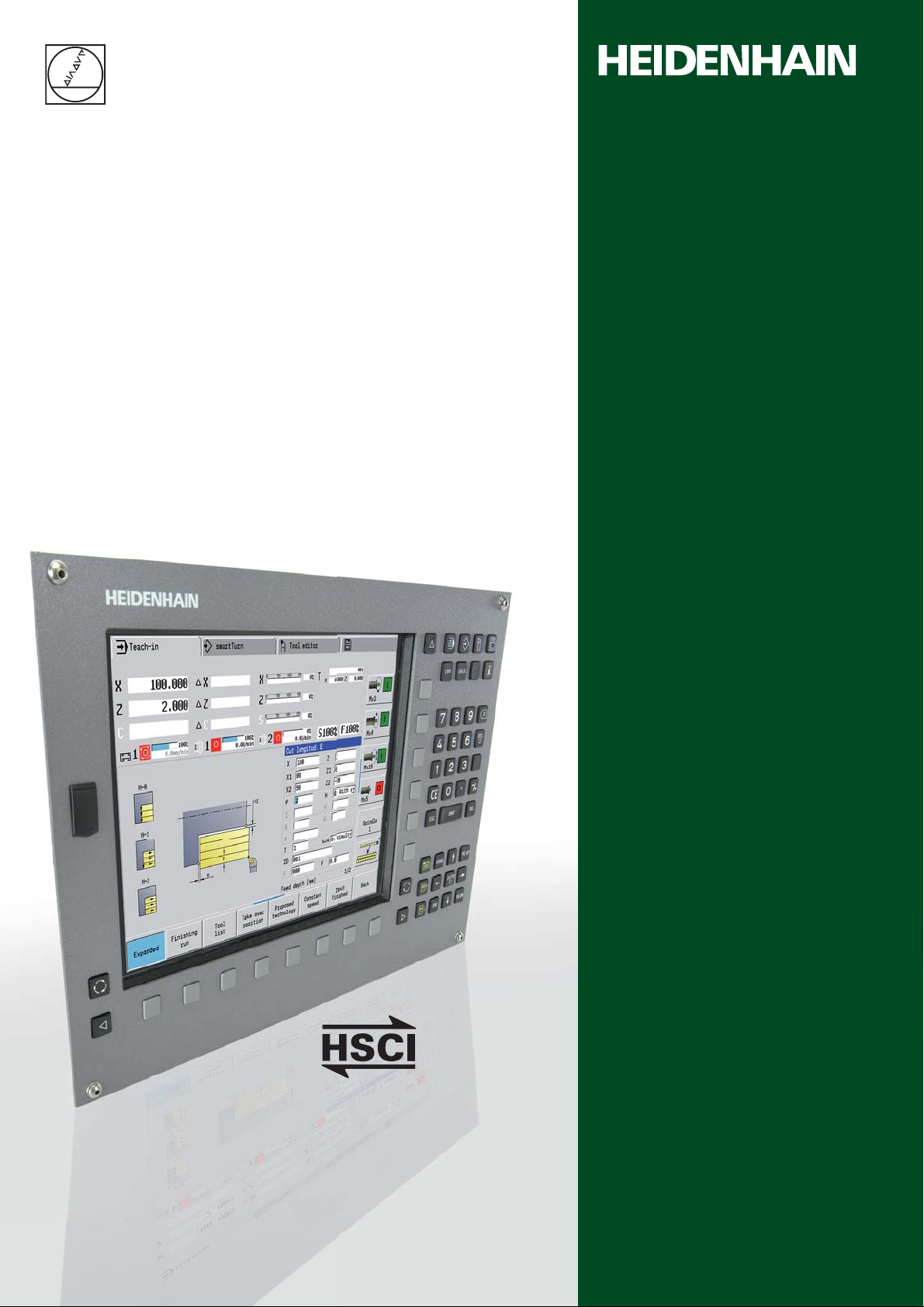
MANU ALplus 620
HSCI
The Contouring Control for
CNC and Cycle Lathes
Infor mation f or the
Machine T ool Builder
August 2010
Page 2
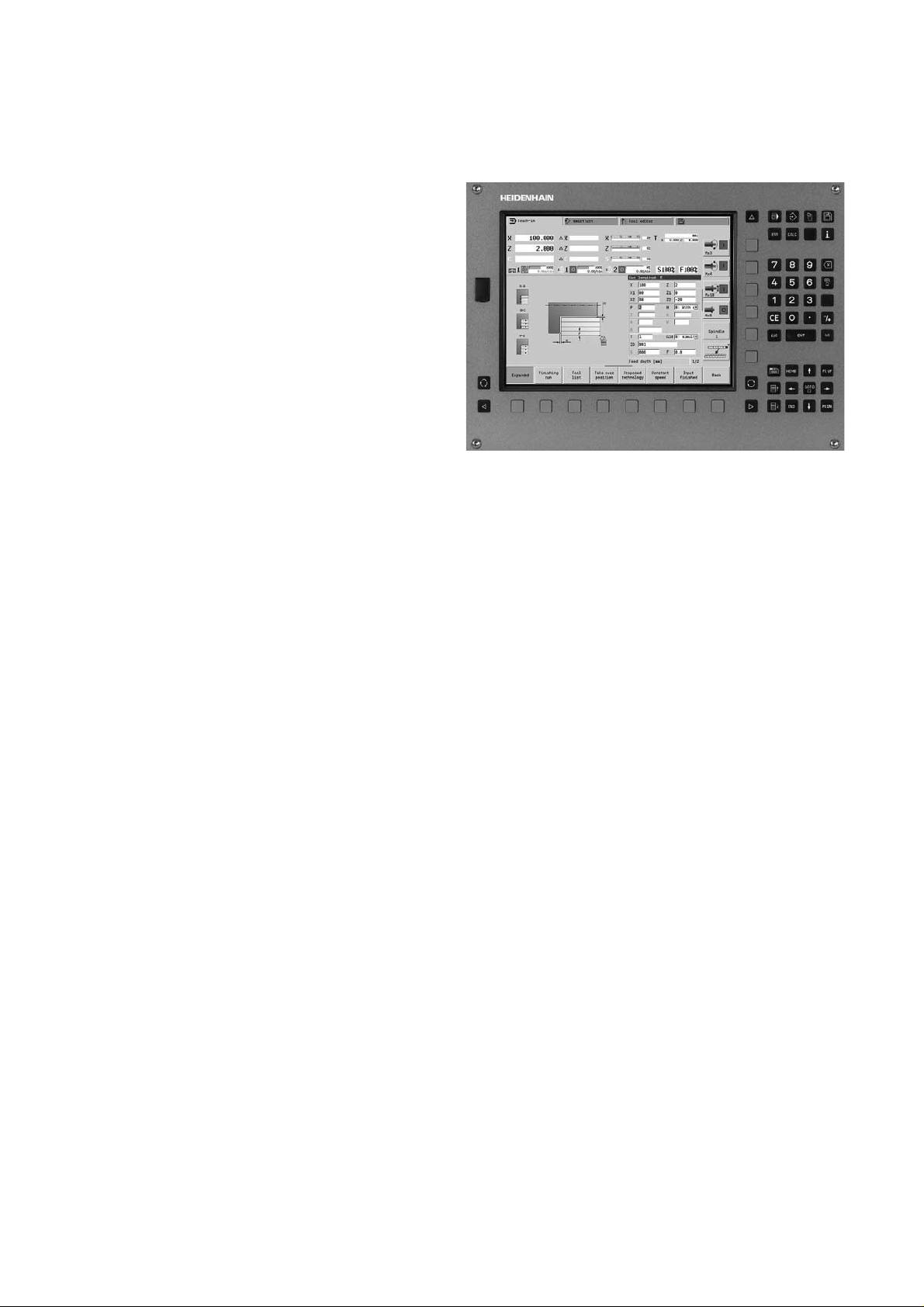
MANU ALplus 620
Contouring Control with Driv e S yst em fr om HEIDENHAIN
MANUALplus 620
Contouring control for lathes with up to 3 axes (X, Z and Y), •
controlled spindle, C axis and driven tools
In addition, a parallel W axis can be offset to the Z axis•
HEIDENHAIN inverter systems and motors recommended•
Compact design: Screen, keyboard and main computer all in one •
unit
12.1-inch TFT color fl at-panel display•
Storage medium for NC programs. CompactFlash memory card•
Cycle programming for t urning, drilling, boring and milling •
operations
smart.Turn programming for turning, boring, drilling and milling •
operations
DIN programming for turning, boring, drilling and milling •
operations
Free ICP contour programming f or t urning and milling contours•
The MANUALplus supports quick change tool posts (Multifi x) •
and tool turrets. The tool carrier can be located in front of or
behind the workpiece.
The MANUALplus also supports vertical lathes.•
USB removable media can be connected•
MANUALplus 620 (MC 6110 T)
System tests
Parts subject t o
wear
Standards
2
Controls, motors and encoders from HEIDENHAIN are in most
cases integrated as components in larger systems. In these cases,
comprehensive tests of the complete system are required,
irrespective of the specifi cations of the individual devices.
In particular the following parts in controls from HEIDENHAIN are
subject to wear:
Buff er battery•
Fan•
Standards (ISO, EN, etc.) apply only where explicitly stated in the
catalog.
Page 3

Contents
Tables with Technical Specifi cations, Mac hine Interf acing,
User Functions and A ccessories
Digital Control Design
Control Systems
Cable Overviews
Technical Description
Overall Dimensions
Documentation
Service
Subject Index
Please refer to the page r eferences in the tables with the
specifi cations.
Page
4
13
14
26
30
46
59
60
61
The feat ures and specifi cations described here apply f or the
following control and NC sof tware v ersion:
MANUALplus 620 ID 548 328-03
Some of these specifi cations require particular machine
confi gurations. Please note also that, for some functions, a special
PLC program must be created by the manufacturer.
This catalog supersedes all previous editions, which thereb y
become invalid.
Subject to change without notice
3
Page 4

Specifi cations
Specifi cations MANUALplus 620 Page
Control systems 14
Main computer MC 611 0 T main computer•
Integrated 12.1-inch TFT color fl at-panel display•
Integral MANUALplus operating panel•
HSCI interface•
Controller unit CC 61xx or
UEC 111 (inverter and system PL integrated) or
UEC 112 (in v erter and sy stem PL integrated)
PLC inputs/outputs PL 6xxx series or on UEC 11x series
Invert er syst ems *
Compact inverter
Modular inverters
1)
Axes
and spindles
Axes Up to 4 closed-loop axes
C axis With spindle motor or separate drive (option)
Driven tool Option
Spindle
Shaft speed
2)
✔
✔
X, Z: standard
Y, W: option
Closed-loop
Max. 60 000 min
–1
15
17
19
*
*
31
31
32
32
32
32
NC program memory
Input resolution and display step
Linear axes X axis: 0.5 µm (diameter: 1 µm)
C axis 0.001°
Interpolation
Straight line In 2 axes (max. ±100 m), optional in 3 principal axes
Circle In 2 axes (radius max. 999 m), optional additional linear interpolation of the
C axis Interpolation of X and Z linear axes with the C axis (option)
1)
As ordered
2)
On motors with two pole pairs
* For further information, refer to the Inverters broc hure (ID 622 420-xx)
** For further information, refer to the brochure MANUALplus 620
250 MB
Z axis: 1 µm
Y axis: 1 µm
W axis: 1 µm
third axis
**
**
**
4
Page 5

Specifi cations MANUALplus 620 Page
Axis feedback contr ol 33
With following error
With feedforward
With jerk limiting
✔
✔
✔
Feed rate
Constant surface speed
Maximum feed rate: · screw pitch [mm]
at f
= 5 000 Hz
PWM
✔
No. of pole pairs in motor
Input mm/min or mm/rev olution
Cycle times of main computer MC 611 0 T
Block processing 3 ms
Cycle times of controller unit
CC 610x/UEC 11x 34
Path interpolation 3 ms
Fine interpolation 0.2 ms
Position controller 0.2 ms
Speed controller 0.2 ms
60 000 min
33
33
35
–1
31
31
31
34
34
34
34
34
34
Current controller f
Per missible t emper at ur e r ang e
T
PWM
INT
3 333 Hz 150 µs
4 166 Hz 120 µs
5 000 Hz 100 µs
6 666 Hz 75 µs
8 333 Hz 60 µs
10 000 Hz 50 µs
Operation: 0 °C to 50 °C
Storage: –20 °C to 60 °C
34
5
Page 6

Mac hine Interf acing
Machine Interf acing MANUALplus 620 Page
Error compensation 37
Linear axis errors
Nonlinear axis errors
Backlash
Hysteresis, reversal peaks
Thermal expansion
Stick-slip friction
Sliding friction
Integral PLC 41
Program format Statement list
Program input via the control Via external USB ke yboard or via soft keys
Program input via PC
Symbolic PLC-NC interface
PLC memory 50 MB
PLC cycle time 21 ms, adjustable
✔
✔
✔
✔
✔
✔
✔
✔
✔
37
37
37
37
37
37
37
41
41
41
41
41
41
PLC inputs/outputs
PLC inputs, 24 V– Via PL or UEC 11x, max. 1024
PLC outputs, 24 V– Via PL or UEC 11x, max. 512
Analog inputs, ±1 0 V Via PL
Inputs for PT 100 thermistors Via PL
Analog outputs, ±1 0 V Via PL
PLC functions
PLC soft keys
PLC positioning
PLC basic program
Max. eight PL 6xxx (one PL 62xx or UEC 11x and max. seven PL 61xx)
✔
✔
✔
✔
19
19
19
19
19
19
41
41
41
42
6
Page 7

Mac hine Interf acing, A ccessories
Machine Interf acing MANUALplus 620 Page
Encoder inputs
UEC 111 UEC 112 CC 61 06 CC 6108
Position 4 5 6 8
Incremental 1 V
PP
Absolute EnDat
Rotational speed 4 5 6 8
Incremental 1 V
PP
Absolute EnDat
36
36
36
36
36
36
36
Commissioning and diagnostic aids 39
DriveDiag Software for diagnosis of digital drive sy stems
TNCopt Software for putting digital control loops into service
Integrated oscilloscope
Trace function
Logic diagram
API DATA function
✔
✔
✔
✔
39
39
40
40
40
40
Table function
OnLine Monitor (OLM)
Log
TNCscopeNT
✔
✔
✔
✔
40
39
40
40
Data interf aces 43
Ethernet (1 00BaseT)
✔
USB 2.0 3 (1 on the front, 2 on the rear)
RS-232-C/V.24 Can only be controlled via PLC
43
43
43
Protocols 43
Standard data transfer
Blockwise data transfer
LSV2
✔
✔
✔
43
43
43
7
Page 8

Accessories MANUALplus 620 Page
Machine operating panel
Electronic handwheels
MB 620 T
One HR 41 0, one HR 130, or up to three HR 150 via HRA 110•
21
22
Up to two HR 180•
Touch probes
One TS 220, TS 440, TS 444, TS 640 or TS 740 workpiece touch probe•
23
One TT 140 tool touch probe•
PLC input/output systems With HSCI interface 19
Basic module System PL
1)
PLB 6204 for 4 I/O modules
19
PLB 6206 for 6 I/O modules
PLB 6208 for 8 I/O modules
Expansion PL
PLB 61 04 f or 4 I/O modules
19
PLB 61 06 f or 6 I/O modules
PLB 61 08 f or 8 I/O modules
I/O modules PLD-H 16-08-00: 1 6 digital inputs and 8 digital outputs, 24 V
19
PLD-H 08-16-00: 8 digital inputs and 16 digital outputs, 24 V
PLA-H 08-04-04: 8 analog inputs ± 1 0 V , 4 analog outputs ± 10 V and 4 analog
PT 1 00 inputs
USB hub
PLC basic program
2)
Programming station
✔
✔
Control software for PCs f or programming, archiving, and training
43
42
*
DataPilot MP/CP 620
Softwar e
PLCdesignNT
KinematicsDesign
TNCremoNT
TNCremoPlus
TNCscopeNT
Driv eDiag
IOconfi g
TNCopt
TeleService
2)
2)
2)
2)
2)
2)
Data transfer software
2)
PLC software dev elopment en vironment
Software for kinematic confi guration
Data transfer software with liv e-screen function
Software for data recording
Software for diagnosis of digital drive sy stems
Software for confi guring PLC I/O and PROFIBUS-DP components
Software for putting digital control loops into service
Software for remote diagnostics, monitoring, and operation
* For further inf ormation, refer to the brochure MANUALplus 620
1)
Integrated in UEC 11x, otherwise necessary once in each HSCI control system
2)
These software products are available to registered customers for do wnloading from the Internet.
42
38
44
44
40
39
19
39
40
8
Page 9

User F unctions
User functions
Standard
Confi guration
Operating modes
Manual operation
Teach-in mode 8 Sequential linking of fi xed cycles, where eac h cy cle is r un immediately after input, or is
Program run
Setup functions •
•
55+0-3
70+0-3
94+0-3
•
•
•
•
•
•
•
Option
Basic version: X and Z axis, spindle
0-3
Positionable spindle and driv en tool
C axis and driven tool
Y axis
W axis (as closed-loop PLC axis)
Digital current and speed control
Manual slide movement through manual direction ke y s, intermediate switch or electronic
handwheels
Graphic support for entering and running cycles without sa ving the machining steps in
alternation with manual machine operation
11
Thread reworking (thread repair in a second w orkpiece set up)
graphically simulated and subsequently saved.
All are possible in single-block and full-sequence modes
DIN PLUS programs
9
smart.Turn programs
8
Cycle programs
Workpiece datum setting
Defi nition of tool-change position
Defi nition of protection zone
Tool measurement by touc hing the w orkpiece
17
Tool measurement with a TT tool touch probe
17
Tool measurement with an optical gauge
17
Workpiece measurement with a TS workpiece touch probe
Programming
Cycle programming
Interactive Contour
Programming (ICP)
8
8
8
8
8
8
8
8+55
8+55
8+55
8+55
8+55
8
8
8
8+9
8/9
8/9
8/9
8/9
8/9
8/9
8/9
Turning cycles for simple and complex contours, as w ell as contours defi ned with ICP
Contour-parallel turning cycles
Recessing cycles for simple or comple x contours, or contours defi ned with ICP
Repetitions with recessing cycles
Recess turning cycles f or simple and comple x contours, as w ell as contours defi ned with ICP
Undercut and parting cycles
Threading cycles for single or multi-start longitudinal, taper or API threads
Cycles for axial and radial drilling, pecking and tapping operations with the C axis
Thread milling with the C axis
Axial and radial milling cycles for slots, fi gures, single surfaces and polygons as well as for
complex contours defi ned with ICP for machining with the C axis
Helical slot milling with the C axis
Linear and circular patterns for drilling, boring and milling operations with the C axis
Context-sensitive help graphics
Transfer of cutting values from technology database
Use of DIN macros in cycle programs
Conversion of cycle programs to smart.Turn programs
Contour defi nition with linear and circular contour elements
Immediate display of entered contour elements
Calculation of missing coordinates, intersections, etc.
Graphic display of all solutions for selection by the user if more than one solution is possible
Chamfers, rounding arcs and undercuts av ailable as f orm elements
Input of form elements immediately during contour creation or by superimposition later
Changes to existing contours can be programmed
9
Page 10

User functions
Standard
Option
ICP (continued) 8/9+55
9+70
8/9+42
C-axis machining on face and lateral surf ace:
Description of individual holes and hole patterns (only in smart.Turn)
Description of fi gures and fi gure patterns for milling (only in smart.Turn)
Creation of freely defi nable milling contours
Y-axis machining on the XY and ZY planes (only in smart.Turn):
Description of individual holes and hole patterns
Description of fi gures and fi gure patterns for milling
Creation of freely defi nable milling contours
DXF import: Import of contours for lathe and milling operations
smart.Turn
programming
DIN PLUS
programming
9+55/70
•
•
•
•
•
•
•
•
•
•
9
9
9
9
9
9
9
9
9+55
9
9
9
9
55
70
8/9
9
The basis is the unit, which is the complete description of a machining block (geometry,
technology and cycle data)
Dialog boxes divided into ov erview and detail forms
Fast navigation between the fi llable forms and input groups via the “smart” keys
Context-sensitive help graphics
Start unit with global settings
Transfer of global values from the start unit
Transfer of cutting values from technology database
Units for all turning and recessing operations for simple contours and ICP contours
Units for boring, drilling and milling operations with the C and Y axes for simple holes, milling
contours and drilling and milling patterns or those programmed with ICP
Special units for activating/deactivating the C axis, subprograms and section repeats
V erifi cation graphics for blank and fi nished part and for C and Y axis contours
Turret assignment and other setup information in the smart.Turn program
Parallel programming
Parallel simulation
Programming in DIN 66025 format
Extended command format (IF... THEN ... ELSE...)
Simple geometry programming (calculation of missing data)
Po w erful machining cycles for turning, recessing, recess turning and thread machining
Po w erful machining cycles for boring, drilling and milling with the C axis
Po w erful machining cycles for boring, drilling and milling with the Y axis
Subroutines
Programming with variables
Contour description with ICP
Program verifi cation graphic for workpiece blank and fi nished part
Turret assignment and other setup information in the DIN PLUS program
Conversion of smart.Turn units into DIN PLUS command sequences
Parallel programming
Parallel simulation
Program verifi cation
graphics
Machining time analysis
10
•
•
•
•
•
•
•
•
•
•
•
Graphic simulation of the cycle process or of the cycle, smart.Turn or DIN PLUS program
Display of the tool paths as wire-frame or cutting-path graphics, special identifi cation of the
rapid-traverse paths
Machining simulation (2-D material-remov al graphic)
Side or face view, or 2-D view of cylindrical surface for v erifi cation of C-axis machining
Display of programmed contours
View of face and YZ plane for verifi cation of Y-axis machining
Three-dimensional display of the workpiece blank and fi nished part
Shifting and magnifying functions
Calculation of machining time and idle machine time
Consideration of switching commands triggered by the CNC
Representation of times per individual cycle or per tool change
Page 11

User functions
Tool database
Standard
Option
•
For 250 tools
10
For 999 tools
•
Tool description can be entered for every tool
•
Automatic inspection of tool-tip position with respect to the contour
•
Compensation of tool-tip position in the X/Y/Z plane
•
Precision path correction via handwheel, transfer ring compensation v alues to the tool table
•
Automatic tool-tip and cut ter radius compensation
•
Tool monitoring for lifetime of the insert (tool tip) or the number of w orkpieces produced
Tool monitoring with automatic tool change after tool insert wear
10
•
Management of multipoint tools (multiple inserts or reference points)
Technology database
Conversational languages
Access to cutting data after defi nition of workpiece material, cutting material and machining
8/9
mode. The MANUALplus distinguishes between 16 mac hining modes. Each workpiecematerial/tool-material combination includes the cutting speed, the main and secondary feed
rates, and the infeed for 16 machining modes.
Automatic determination of the mac hining modes from the cy cle or the machining unit
8/9
The cutting data are entered in the cycle or in the unit as def ault v alues
8/9
9 workpiece-material/tool-material combinations (144 entries)
8/9
62 workpiece-material/tool-material combinations (992 entries)
10
•
Chinese (simplifi ed), Chinese (traditional), Czech, Danish, Dutch, English, Finnish, French,
German, Hungarian, Italian, Polish, P ortuguese, Russian, Spanish, Swedish
41
For more conv ersational languages, see Option
11
Page 12

Options
Option
number
0
1
2
3
8
9
10
11
Option ID Comment
Additional axis 354 540-01
353 904-01
353 905-01
367 867-0 1
Software option 1
Teach-in
Software option 2
smart.Turn
Software option 3
Tools and technology
Software option 4
Thread cutting
632 226-01
632 227-0 1
632 228-01
632 229-01
Additional control loops 1 to 4
Cycle programming
Contour description with ICP•
Cycle programming•
Technology database with 9 workpiece-material/tool-material combinations•
smart.Turn
Contour description with ICP•
Programming with smart.Turn•
Technology database with 9 workpiece-material/tool-material combinations•
Tools and technology
Tool database expanded to 999 entries•
Technology database expanded to 62 w orkpiece-material/tool-material •
combinations
Tool life monitoring with ex change tools•
Threads
Thread recutting•
Handwheel superimposition during thread cutting•
17
41
42
55
70
94
Touch probe functions 632 230-01
Additional language 530 184-01
530 184-02
530 184-03
530 184-04
530 184-06
530 184-07
530 184-08
530 184-09
530 184-1 0
DXF- import 632 231-01
C-axis machining 633 944-01
Y-axis machining 661 881 -01
W-axis machining 679 67 6-01
Tool measurement and workpiece measur ement
Determining tool-setting dimensions with a tool touch probe•
Determining tool-setting dimensions with an optical gauge•
Automatic workpiece measurement with a touch probe•
Slovenian
Slovak
Latvian
Norwegian
Korean
Estonian
Turkish
Romanian
Lithuanian
DXF import
Import of DXF contours•
C-axis machining
Y-axis machining
Support of W axis
12
Page 13
Digital Control Design
Digital in every
way
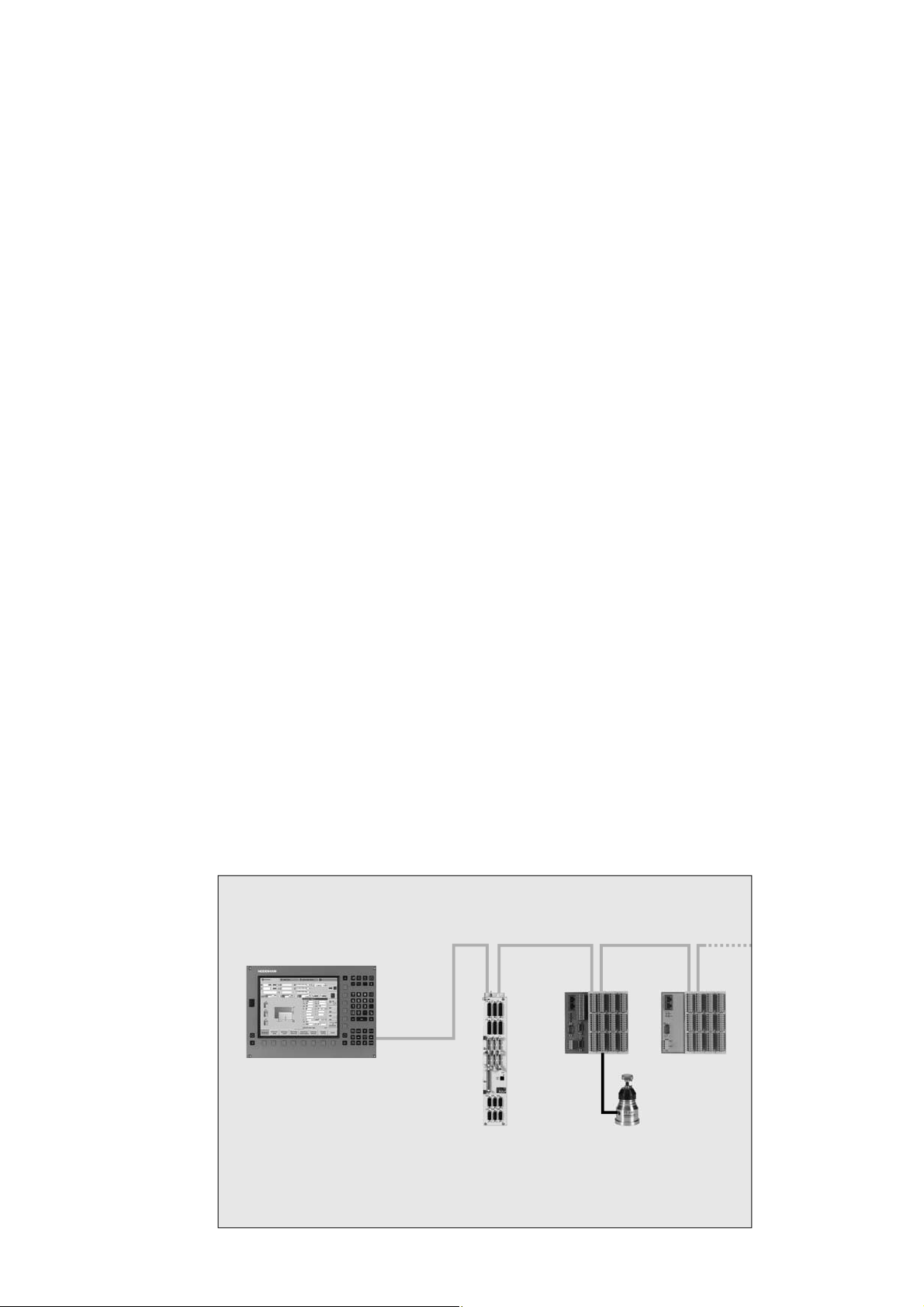
HSCI
In the uniformly digital control design from HEIDENHAIN, all
components are connected to each other via purely digital
interfaces: The control components are connected via HSCI
(HEIDENHAIN Serial Controller Interface), the new real-time
protocol from HEIDENHAIN for Fast Ethernet, and the encoders
are connected via EnDat 2.2, the bidirectional interface from
HEIDENHAIN. This achieves a high degree of av ailability for the
entire system. It can be diagnosed and is immune to noise—from
the main computer to the encoder . These outstanding properties
of the uniformly digital design from HEIDENHAIN guarantee not
only very high accuracy and surface quality, but rapid tra v erse
speeds as well. Please refer to the Unif ormly Digital tec hnical
Information sheet for more detailed information.
HSCI, the HEIDENHAIN Serial Controller Interface, connects the
main computer , controller(s) and other control components.
HSCI is based on 1 00BaseT Ethernet hardw are. A special interf ace
component developed by HEIDENHAIN has shortened cy cle times
for data transfer.
Main advantages of the contr ol design with HSCI:
Hardware platform for fl exible and scalable control system •
(e.g. local axis systems)
High noise immunity due to digital communication between •
components
Greater permissible cable lengths within the overall system•
More PLC inputs and outputs•
Simpler wiring (initial operation, confi guration)•
Inverters connected as before via w ell-pro v en PWM interf ace•
CC or UEC controller units, up to eight PL 6xxx input/output
modules, and an MB machine operating panel can be connected
to the serial HSCI bus of the MC main computer . The HR
handwheel is connected directly to the machine operating panel.
The combination of visual display unit and main computer housed
in the operating panel is especially advantageous. All that is
required is the power supply and an HSCI line to the controller in
the electrical cabinet.
HSCI HSCI HSCI
HSCI
MC main computer
PLC inputs/
outputs PL
CC controller unit Touch probe
13
Page 14

HSCI Control S yst em MANU ALplus 620
Overview
The MANUALplus 620 contouring control consists of the follo wing
components:
Type Page
MANUALplus 620
Accessories Machine operating
Main computer
with 12.1
Memory card
NC software license
Pow er supply unit
Controller unit
Control loops
PLC inputs/
outputs
System PL
Expansion PL
Connecting cables 26
panel
Electronic
handwheels
Touch probes
,,
screen
MC 6110 T 15
CFR 16
SIK component 16
PSL 130 (as required)
PSL 135 (for use with non-HEIDENHAIN
inverter systems)
UEC 11 1
Max. 4
PL 6xxx series
Integrated
Max. 7 PLB 61 0x
MB 620 T 21
HR 410, HR 1 80, HR 130 or HR 150 22
TS 220 or
TS 440 or
TS 444 or
TS 640 or
TS 740
1)
UEC 112
Max. 5
PL 6xxx series
Integrated
Max. 7 PLB 61 0x
1)
PSL 130 20
CC 6106
Max. 6
PL 6xxx series
One PLB 620x
Max. 7 PLB 61 0x
CC 6108
Max. 8
17
19
24
14
1)
Inverter and system PL integrated
TT 140
Page 15
Main Computer
Main computer
MC 6110 T
The MC 6110 T main computer consists of
1.0 GHz Celeron M processor•
1 GB RAM memory•
MANUALplus control panel•
12.1-inch TFT color fl at-panel display with soft keys, •
resolution: 1 024 x 768 pixels
HSCI interface to the controller unit and to other control •
components
Further interf aces, such as Ethernet, USB, RS-232-C/V.24•
To be ordered separately , and installed in the main computer by
the OEM:
CFR• memory card with the NC sof tware
SIK component• (System Identifi cation Key) for enabling control
loops and options
The following HSCI components are necessary for operation of the
MANUALplus 620:
PL 62xx• PLC input/output unit (system PL; integrated in
UEC 11x)
Weight 5.6 kg
ID 731 604-xx
Po w er supply If a CC 61 0x controller unit is used, the PSL 130 supplies 24 V of
power to the main computer and other HSCI components. If a
UEC controller unit is used, a PSL 130 is only required if the
current consumption is greater than 3.5 A.
Options
The capabilities of the MANUALplus 620 can also be adapted
retroactively with options to meet new requirements. These
options are described on page 11. T he y are enabled b y entering
keywords based on the SIK number, and are saved in the SIK
component. Please indicate your SIK number when ordering new
options.
15
Page 16
Main Computer—CFR Memory Card, SIK Component
CFR CompactFlash
SIK component
Master keyword
(general key)
The NC software f or the MANUALplus 620 is on the
CFR CompactFlash memory card (CFR = CompactFlashRemovable).
It is also the memory medium for NC programs (up to 250 MB)
and the PLC program (up to 50 MB).
MANUALplus 620 ID 733 606-51
The SIK component contains the NC software license for enabling
control loops and software options. It gives the main computer an
unambiguous ID code—the SIK number . The SIK component is
ordered and shipped separately . It must be inserted in a special
slot in the MC 611 0 T main computer .
The SIK component with the NC software license is a v ailable in
various versions, depending on the enabled control loops.
Additional control loops can be enabled later by entering a
keyword. HEIDENHAIN pro vides the k e yw ord, which is based on
the SIK number . When ordering, please indicate the SIK number of
your control. When the keywords are entered in the control, they
are saved in the SIK component. This enables and activates the
options. Should service become necessary, the SIK component
must be inserted in the replacement control to enable all required
options.
There is a master keyw ord (general k e y) f or putting the
MANUALplus 620 into service that will unlock all control loop
options for a duration of 90 days. After this period, only those
options with the correct keywords will be activ e. The general key is
activated using a soft k e y.
SIK component
NC softwar e
license and
enabling of control
loops
NC softwar e license SIK with software license and enabling for ID
Additional axes Option
There are always 3 control loops enabled in the basic version. The
controller unit must be capable of handling the number of
activated control loops. Maximum numbers:
UEC 111: 4 control loops•
UEC 112: 5 control loops•
CC 61 06: 6 control loops•
CC 61 08: 7 control loops•
Three control loops, including options:
Teach-in (option 8)•
smart.Turn (option 9)•
Thread recutting (option 11)•
C-axis machining (option 55)•
number
1st additional axis (4th control loop) 0 354 540-01
733 604-53
ID
16
2nd additional axis (5th control loop) 1 353 904-01
3rd additional axis (6th control loop) 2 353 905-01
4th additional axis (7th control loop) 3 367 867-01
Page 17
Controller Unit
Controller unit
Number of
control loops
V ersions Controller units and main computers operate in any desired
CC 610x
Due to the very short cycle times of the position, velocity and
current controllers, the controller units from HEIDENHAIN are
equally suited for conventional driv es, f or direct driv es (linear
motors, torque motors) and for HSC spindles. They permit a high
loop gain and short reaction times to changing machining forces,
and so make the high contour accuracy and surface quality of the
workpiece possible.
The number of enabled control loops depends on the SIK (see
Main Computer ), or on additionally enabled control loops, which
can also be ordered as needed at a later date.
combination. HEIDENHAIN off ers the f ollo wing v ersions:
Modular CC 61 0x controller unit with PWM interf ace to the •
inverters
Compact UEC 11x controller units with integrated inverter•
The CC 61 0x controller unit features:
Position controller•
Speed controller•
Current controller•
HSCI interfaces•
PWM interfaces to the UM 1xx, UR 2xx, and UE 2xx power •
modules
Interfaces to the speed encoders•
Interfaces to the position encoders•
Interfaces for the pow er supply (supply via UVR 1xx D, UE 2xx D •
or UR 2xx)
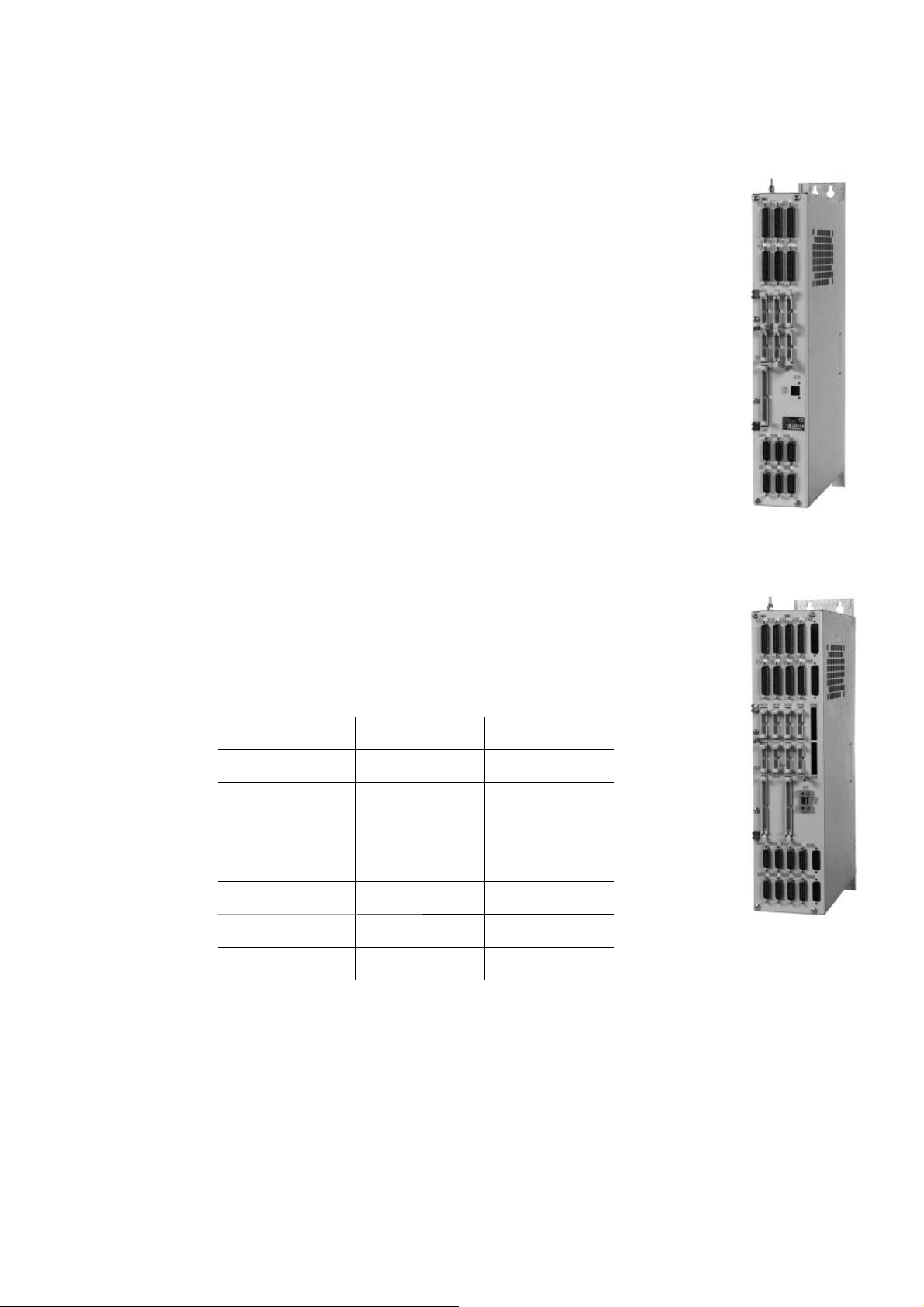
CC 6106
CC 6106 CC 6108
Digital control loops
Speed inputs
Position inputs
PWM outputs
Weight
ID
Max. 6 Max. 8
PP
PP
or
or
6 x 1 V
EnDat 2.2
6 x 1 V
EnDat 2.2
68
4.1 kg 4.7 kg
662 636-xx 662 637-01
8 x 1 V
EnDat 2.2
8 x 1 V
EnDat 2.2
PP
PP
or
or
CC 6108
17
Page 18
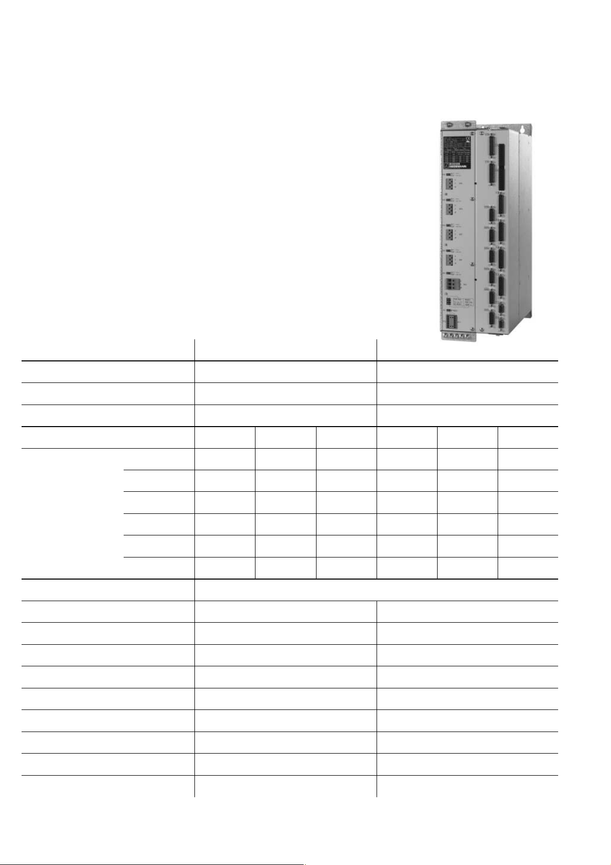
UEC 11x
Controller Position controller•
Inverters Po w er electronics•
System PL Interfaces for one workpiece touch probe and one tool •
Along with the controller with PLC inputs and outputs, the
UEC 11x compact controller units also include an inverter with
integrated braking resistor . They offer a complete solution for
machines with a limited number of axes and lo w po w er demands.
Speed controller•
Current controller•
HSCI interface•
Interfaces to the speed and position encoders•
Connections for axis motors and spindle motor•
Braking resistor•
Connections for motor holding brakes•
touch probe
PLC with 38 inputs and 23 outputs (of which 7 outputs can be •
switched off) freely available (expandable via PL 61xx)
Confi guration with IOconfi g • PC software
UEC 111 UEC 112
Controller
Speed inputs
Position inputs
Inverters
Rated curr ent I
Max. current I
N
max
/
1)
for PWM frequency
Pow er supply
Rated power of DC link
Peak pow er
2)
of DC link 18 kW/25 kW 18 kW/25 kW
Pow er loss (appr ox.) at I
4 digital control loops 5 digital control loops
4 x 1 V
4 x 1 V
or EnDat 2.2 5 x 1 V
PP
or EnDat 2.2 5 x 1 VPP or EnDat 2.2
PP
or EnDat 2.2
PP
2 axes 1 axis Spindle 3 axes 1 axis Spindle
3 333 Hz 6.0/12.0 A 9.0/18.0 A 24.0/36.0 A 6.0/12.0 A 9.0/18.0 A 24.0/36.0 A
4 000 Hz 5.5/11 .0 A 8.3/16.5 A 22.0/33.0 A 5.5/11.0 A 8.3/1 6.5 A 22.0/33.0 A
5 000 Hz 5.0/1 0.0 A 7.5/1 5.0 A 20.0/30.0 A 5.0/1 0.0 A 7.5/1 5.0 A 20.0/30.0 A
6 666 Hz 4.2/8.4 A 6.3/12.6 A 16.8/25.2 A 4.2/8.4 A 6.3/1 2.6 A 1 6.8/25.2 A
8 000 Hz 3,6/7.3 A 5.5/1 1.0 A 1 4.6/21.9 A 3,6/7.3 A 5.5/11.0 A 14.6/21.9 A
10 000 Hz 3.0/6.0 A 3.0/6.0 A 12.2/1 8.3 A 3.0/6.0 A 3.0/6.0 A 12.2/18.3 A
3 x 400 V (± 10 %); 50 Hz to 60 Hz or 3 x 480 V (± 10 %); 50 Hz to 60 Hz
14 kW 14 kW
N
450 W 450 W
DC-link voltage
Integral braking r esistance
Pow er pac k f or HSCI components
Module width
Weight (approx.)
ID
1)
Axes: 0.2 s Cyclic duration factor for duty cycle time of 10 s with 70 % rated current preload
Spindle: 10 s Cyclic duration factor f or duty cycle time of 60 s with 70 % rated current preload
2)
1st value: 40 % Cyclic duration f actor f or duty cycle time of 10 minutes (S6-40 %)
565 V 565 V
2.1 kW/27 kW 2.1 kW/27 kW
24 V/3.5 A 24 V/3.5 A
175 mm 175 mm
20 kg 20 kg
625 777-xx 625 779-xx
2nd value: 4 s Cyclic duration factor f or duty cycle time of 20 s
18
Page 19
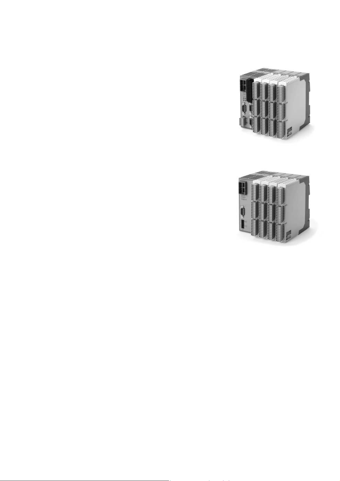
PL 6xxx PLC Input/Output Sy stems with HSCI
Basic modules
System PL
PLB 6204
PLB 6206
PLB 6208
Expansion PL
PLB 61 04
PLB 61 06
PLB 61 08
The PLC inputs and outputs are available via e xternal modular
PL 6xxx PLC input/output systems. These consist of a basic
module and one or more I/O modules, and are connected to the
MC main computer via the HSCI interface. The PL 6xxx units are
confi gured with the PC software IOconfi g.
There are basic modules with HSCI interf ace a v ailable f or 4, 6 or
8 I/O modules. They are mounted on standard NS 35 rails
(DIN 46 227 or EN 50 022).
Supply voltage 24 V–
Po w er consumption Appro x. 20 W
Weight 0.36 kg (bare)
One required per control system•
Includes connections for TS touch probes (except with UEC)•
Safety-relev ant inputs/outputs•
For 4 I/O modules ID 591 832-01
For 6 I/O modules ID 630 054-01
For 8 I/O modules ID 630 055-01
For connection to the system PL to increase the number of PLC
inputs/outputs
For 4 I/O modules ID 591 828-01
For 6 I/O modules ID 630 058-01
For 8 I/O modules ID 630 059-01
PL 62xx
Up to eight PL 6xxx units can be connected to the control (one
PLB 62xx or UEC 11x and up to seven PLB 61xx). The maximum
cable length results from the maximum permissible length of the
HSCI chain of 100 m.
I/O modules With HSCI interface:
There are I/O modules with digital and analog inputs and outputs.
For partially occupied basic modules, the unused slots must be
occupied by an empty housing.
PLD-H 16-08-00
PLD-H 08-16-00
PLA-H 08-04-04 Analog module for PL 6xxx with
Empty housing
I/O module with 16 digital inputs and 8 digital outputs
I/O module with 8 digital inputs and 16 digital outputs
Total current Outputs 0 to 7: † 8 A per output
(† 8 A simultaneously)
Po w er output Max. 200 W
Weight 0.2 kg
PLD-H 16-08-00 ID 594 243-01
PLD-H 08-16-00 ID 650 891-01
8 analog inputs for ±10 V
4 analog outputs for ±10 V
4 analog inputs for PT 100 thermistors
Weight 0.2 kg
ID 675 572-01
For unused slots
ID 383 022-01
PL 61xx
IOconfi g
(accessory)
PC software for confi guring the PL 6xxx and PL 550 (PROFIBUS-DP)
components
19
Page 20

P o w er Supply f or HSCI Components
To power the HSCI components HEIDENHAIN offers the PSL 1 3x
power supply units.
The PSL 13x is pro vided either with line and DC-link v oltage or only
with line voltage.
The PSL 13x pro vides the safely separated +24 volt NC power
supply required for the HSCI components by EN 61 800-5-1. The
NC and PLC are powered by two separate, metallically isolated
power supply units.
Supply voltage Line voltage: 400 V~ ± 10 % 50 Hz, and
DC-link voltage 400 V– to 750 V–
Po w er consumption: Max. 1000 W
Outputs NC: 24 V–/† 20 A (double isolation)
5 V–/† 1 6 A (only with PSL 135)
electrically connected with 24 V NC
PLC: 24 V–/† 20 A (basic isolation)
Total: Max. 32 A/750 W
The PSL 130 serves as a 24-V power supply unit for supplying the
HSCI components. If a UEC controller unit is used, then the
PSL 130 is not necessary if the total current consumption of the
connected HSCI components does not exceed 3.5 A.
PSL 130
PSL 130
PSL 135
Conductor bars
HSCI component MC 6120 TE 615 QT PL 62xx
(incl. TS
and TT)
Current
consumption
When a non-HEIDENHAIN inverter system is used (e.g. Siemens
SIMODRIVE 611 D), the PSL 135 power supply unit is required for
supplying the CC controller unit and the MC main computer .
Module width Degree of
50 mm IP 20 2.1 kg 575 047-xx
50 mm IP 20 2.5 kg 627 032-xx
For connecting the PSL 1 30 to the dc-link v oltage.
If the 24 V po w er supply unit PSL 130 is arranged to the left ne xt
to the UV(R) 1xx D or UE 2xx D/UR 2xx D, it can be connected
directly to the DC link through special conductor bars. The
conductor bars are insulated. The +U
blue. The following lengths are available:
1.8 A 1.1 A 0.5 A 0.2 A
Weight ID
protection
bar is red and the –Uz bar is
z
PL 61xx
PSL 135
20
Length Red Blue
150 mm (UVR 120 D/1 30 D/UV 130) 682 996-0 1 682 996-51
200 mm (UVR 140 D/150 D/UE 21x D) 682 996-02 682 996-52
250 mm (UVR 160 D/UR 2xx D) 682 996-03 682 996-53
Page 21

Accessories
Mac hine Operating Panel
Machine operating
panel
MB 620 T
HSCI adapter
21 exc hangeable snap-on k e y s, freely defi nable via PLC•
Operating elements: 12 axis ke y s, 16 function keys, NC start•
NC stop
Snap-On Keys); emergency stop button, control voltage on
2 holes for additional keys or detachable-key switch
HSCI interface•
8 PLC inputs and 8 PLC outputs•
Spindle-speed and feed-rate ov erride potentiometers•
Weight 0.9 kg
ID 737 610-01
Po w er supply: 24 V , current consumption: 1 A•
Confi guration of the PLC inputs/outputs with the IOconfi g •
PC software
1)
Keys illuminated
For the OEM mac hine operating panel.
The PLB 600 1 HSCI adapter is required in order to connect an
OEM-specifi c machine operating panel to the iTNC 620 HSCI. The
override potentiometers of the TE 6xx and the HR xxx handwheel
for spindle speed and feed rate are also connected to this adapter.
1)
, spindle start, spindle stop (all are snap-on keys; see
1)
,
1)
;
MB 620 T
PLB 6001 HSCI interface•
Connection for HR xxx•
Terminal for 64 inputs and 32 outputs (inputs/outputs for keys/•
key illumination)
Connection for spindle speed override and feed-rate override•
Screw fastening or DIN-rail mounting•
Confi guration of the PLC inputs/outputs with the IOconfi g •
PC software
Weight Approx. 1.2 kg
ID 668 792-01
21
Page 22

Electronic Handwheels
Function
HR 180
The standard MANUALplus 620 supports the use of electronic
handwheels.
The following handwheels can be installed:
For connection to the position inputs,•
up to two HR 180 panel-mounted handwheels
For connection to the handwheel input of the MB mac hine •
operating panel or the PLB 6001 HSCI adapter,
one HR 410 portable handwheel, or
one HR 130 panel-mounted handwheel, or
up to three HR 150 panel-mounted handwheels through the
HRA 110 handwheel adapter
Any combination is possible. Cycle machines, for example,
typically use HR 180 and—if required—one HR 41 0, or if there are
not enough position inputs, up to three HR 150 handwheels via
the HRA 11 0 handwheel adapter. CNC machines usually require
only one HR 130 or HR 410.
Incremental traverse of the slide:•
1 µm/1 0 µm/100 µm per increment
The handwheels with detent have 100 stops per revolution•
Positioning the slide to the starting position of MANUALplus •
cycles
Fine adjustment of tool position•
Panel-mounted handwheel with ergonomic control knob for
connection to a position encoder input.
HR 130
HRA 110
Weight Approx. 0.7 kg
HR 180 with detent ID 540 940-08
Panel-mounted handwheel with ergonomic control knob for
connection to the handwheel input.
Weight Approx. 0.7 kg
HR 130 without detent ID 254 040-05
HR 130 with detent ID 540 940-01
Handwheel adapter for connection of up to three HR 150 panelmounted handwheels and two switches for axis selection and f or
selecting the interpolation factor. The fi rst two handwheels are
permanently assigned to axes 1 and 2. The third handwheel is
assigned to the axes over a selection switch (accessory) or by
machine parameters. The position of the second selection switch
(accessory) is evaluated by the PLC, for example to set the proper
interpolation.
HRA 110
ID 261 097-xx
Weight Approx. 1.5 kg
Handwheel selection switch with knob and cable
ID 270 908-xx
HR 150
22
Panel-mounted handwheel with ergonomic control knob for
connection to the HRA 110 handwheel adapter.
Weight Approx. 0.7 kg
HR 150 without detent ID 540 940-06
HR 150 with detent ID 540 940-07
Page 23

HR 410
HR 41 0 v ersion Mechanical detent
With Without
Portable electronic handwheel with
Keys for the selection of 5 axes•
Traverse direction keys•
Keys for three preset feed rates•
Actual-position-capture k e y•
Three keys with machine functions (see below)•
Two permissive buttons (24 V)•
Emergency stop button (24 V)•
Magnetic holding pads•
All keys are designed as snap-on keys and can be replaced by keys
with other symbols. (For ke y symbols see Snap-On Keys.)
Weight Approx. 1 kg
Standard assignment with the
FCT A, FCT B, FCT C function
keys
For PLC basic program with
NC start/stop, spindle start
With spindle right/left/stop – 296 469-54
– 296 469-53
535 220-05 296 469-55
HR 410
23
Page 24

Touch P robes
Wor kpiece
measurement
TS 220 TTL version
TS 440 Compact dimensions
TS 444 Compact dimensions, battery-free power supply through
TS 640 Standard touch probe with wide-range infrared transmission and
Touch probes f or w orkpiece measurement are connected via the
system PL 62xx or the UEC 11x. T hese touch probes generate a
trigger signal that saves the current position value to the NC. For
more information on the touch probes, ask f or our brochure or
CD-ROM entitled Touch Probes.
The TS touch trigger probe has a stylus with which it probes
workpieces. The MANUALplus 620 provides a sample cycle for
measuring workpieces. Additionally, the machine manufacturers
off er specially de v eloped measuring cy cles that are individually
adapted to the machine series. The touch probes are av ailable with
various taper shanks. Assorted styli are available as accessories.
Touch probe with cable connection f or signal tr ansmission for
machines with manual tool change:
Touch probe with infr ar ed signal tr ansmission f or machines with
automatic tool change (e.g. turret magazine):
integrated air turbine generator over central compressed air supply
long operating time
TS 220
TS 740 High probing accuracy and repeatability, low probing force
The infrared transmission is established between the TS touch
probe and the SE transceiver unit. The following SE units can be
combined with the TS touch probes:
SE 640 for integration in the machine’ s w orkspace
SE 540 for integration in the spindle head
Tool calibration
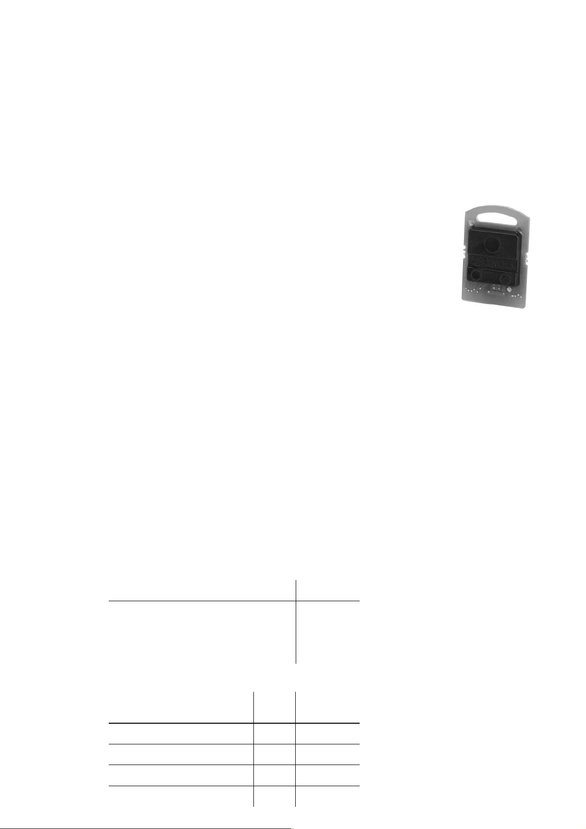
TT 140 With the triggering TT 140 touch pr obe, the cuboid probe contact
Cuboid probe
contact
The touch probe f or tool measurement from HEIDENHAIN is suited
for probing tools directly on the machine. The MANUALplus 620
off ers standard cycles. The MANUALplus 620 automatically sav es
the results of measurement in a tool table. It is also possible to
measure tool wear between two machining steps. After measuring
the tool, the MANUALplus 620 compensates the tool data
automatically for subsequent machining.
is defl ected from its rest position upon contact with a stationary or
rotating tool, sending a trigger signal to the MANUALplus 620.
The standard TT 140 is shipped with a disk-shaped probe contact.
For use with lathes, it must be replaced by the cuboid probe
contact.
ID 67 6 497-01
TS 440 with SE 640
TT 140
24
Page 25

Snap-On Keys
The snap-on keys make it easy to replace the key symbols. In this way, the MB machine operating panel and the
HR 41 0 handwheel can be adapted to different requirements.
The snap-on keys are available in packs of 5 keys.
Axis keys
Orange
ID 330 816-42
ID 330 816-24
ID 330 816-43
ID 330 816-37
Gray
Machine functions
ID 330 816-26
ID 330 816-23 ID 330 816-25
ID 330 816-95
ID 330 816-96
ID 330 816-97
ID 330 816-98
ID 330 816-99
ID 330 816-0A
ID 330 816-0B
ID 330 816-0C
ID 330 816-70
ID 330 816-0X
ID 330 816-36
ID 330 816-69
ID 330 816-0G
ID 330 816-0H
ID 330 816-71
ID 330 816-72
ID 330 816-63
ID 330 816-64
ID 330 816-18
ID 330 816-17
ID 330 816-75
ID 330 816-38
ID 330 816-45
ID 330 816-0W
ID 330 816-0V
ID 330 816-0N
ID 330 816-0M
ID 330 816-67
ID 330 816-68
ID 330 816-21
ID 330 816-20
ID 330 816-0P
ID 330 816-0T
Y
Y
Z
ID 330 816-0R
ID 330 816-0D
ID 330 816-0E
ID 330 816-65
ID 330 816-66
ID 330 816-19
ID 330 816-16
ID 330 816-0L
ID 330 816-0K
ID 330 816-86
Spindle functions
Other keys
ID 330 816-1Y
ID 330 816-30
ID 330 816-31
ID 330 816-32
ID 330 816-73
ID 330 816-74
ID 330 816-08
ID 330 816-09 ID 330 816-46
ID 330 816-01
ID 330 816-61
(green)
ID 330 816-11
(red)
ID 330 816-12
ID 330 816-76
ID 330 816-77
ID 330 816-78
ID 330 816-79
ID 330 816-80
ID 330 816-0S
ID 330 816-41
ID 330 816-50
ID 330 816-33
ID 330 816-34
ID 330 816-35
ID 330 816-81
ID 330 816-82
ID 330 816-83
ID 330 816-84
ID 330 816-89
ID 330 816-85
(red)
ID 330 816-47ID 330 816-40
(green)
ID 330 816-90
ID 330 816-27
ID 330 816-28
ID 330 816-29
ID 330 816-87
ID 330 816-88
ID 330 816-94
ID 330 816-0U
ID 330 816-91
ID 330 816-3L
ID 330 816-48
ID 330 816-93
0
ID 330 816-0Y
ID 330 816-4M
ID 330 816-3M
ID 330 816-49
ID 330 816-22
ID 330 816-92
ID 330 816-3N
25
Page 26

Cable Overview
Control Sy stem with UEC 11x
60m
07.06.2010
12m
VL: Extension cable
for separation points with connecting cable
HSCI total length 100 m
for extending existing connecting cable
PP
1 V
PP
1 V
RCN 729
RCN 226
RCN 228
LC
LC x83
631-xx max. 6m
533
60m
RCN 729
RCN 226
RCN 228
60m
PP
1 V
30m
LC x83
1m
1m
LC x83
631-xx max. 6m
533
60m
LB/LS
max. 9m
PP
1 V
298 429-xx
298 430-xx
MB 620 T
739 545-xx
MC 6110 T
X500
X502
X
X500
310 199-xx
309 783-xx
X502
UEC 11x
558 714-xx
Position inputs
X201 ... X204 (UEC 111)
X201 ... X205 (UEC 112)
PLC I/O
VL
323 897-xx
332 115-xx
X15 ... X18 (UEC 111)
X15 ... X19 (UEC 112)
23 outputs
38 inputs
509 667-xx
Adapter connector 544 703-01
for spindle (if necessary)
Only for connection of the KTY
2)
1)
1)
289 440-xx
VL
323 897-xx
2)
Voltage controller 5 V
368 210-01
336 376-xx
Speed inputs
289 440-xx
KTY
KTY
Voltage controller 5 V
383 951-01
289 440-xx
1)
336 376-xx
Axes: 15m
26
HSCI
618 893-xx
HSCI
618 893-xx
PP
1 V
VL
336 847-xx
VL (max. 6m)
30m
Axes + spindle:
Voltage controller 5 V
336 847-xx
60m
Axes + spindle:
VL
340 302-xx
370 226-01
Voltage controller 5 V
370 224-01
VL (max. 6m)
340 302-xx
EnDat 2.1 interface
Axes: 60m
Page 27

Control Sy stem with CC 610x
60m
07.06.2010
12m
PP
1 V
PP
1 V
RCN 729
RCN 226
RCN 228
LC
LC x83
631-xx max. 6m
533
60m
RCN 729
RCN 226
RCN 228
60m
PP
1 V
30m
LC x83
1m
1m
LC x83
631-xx max. 6m
533
60m
LB/LS
PP
1 V
VL: Extension cable
HSCI total length 100 m
for separation points with connecting cable
for extending existing connecting cable
MC 6110 T
X500
298 429-xx
298 430-xx
X502
MB 620 T
739 545-xx
X
310 199-xx
X500
309 783-xx
558 714-xx
Position inputs
X201 ... X206
CC 6106
X502
VL
323 897-xx
332 115-xx
X15 ... X20
X500
X51...X56
PWM
out
Adapter connector 544 703-01
1)
509 667-xx
Voltage controller 5 V
for spindle (if necessary)
Only for connection of the KTY
2)
1)
289 440-xx
289 440-xx
VL
323 897-xx
2)
368 210-01
336 376-xx
Speed inputs
1)
KTY
Axes: 15m
Voltage controller 5 V
383 951-01
max. 9m
KTY
289 440-xx
336 376-xx
HSCI
618 893-xx
X502
HSCI
618 893-xx
VL
340 302-xx
370 226-01
Voltage controller 5 V
370 224-01
VL (max. 6m)
340 302-xx
EnDat 2.1 interface
Axes: 60m
VL (max. 6m)
336 847-xx
60m
Axes + spindle:
Voltage controller 5 V
VL
336 847-xx
PL 610x
HSCI
PL 620x
30m
PP
1 V
X502
X500
HSCI
618 893-xx
Axes + spindle:
27
Page 28

Inv erter S y stems
X51 ... X62
(if needed)
250 479-07...-16
24V
X51 ... X62
250 479-07...-16
325 817-xx
X79
X69
325 816-xx
X69
See Motors catalog
for power cable to motor
UM 1xx UP 110
250 479-07 ... -16
(if needed)
ZKF 1xx
UM 1xxUM 1xx
250 479-07 ... -16
CC 6106
UM 111
Compact inverter (regenerative)
UR 2xx
Uz Uz Uz
X69
325 817-xx
325 816-xx
See Motors catalog
for power cable to motor
PSL 130
15m
D
Uz Uz Uz Uz Uz Uz Uz
UVR
1xx
24V
PSL 130
EPCOS xx
Line filter
X79
X69
15m
Three-phase
ac capacitor
348 993-01
KDR 120
Line filter
EPCOS 35 A
L1 L2 L3
L1 L2 L3
Compact inverter (nonregenerative)
L1 L2 L3
HSCI
Uz Uz Uz Uz
UEC 11x
Uz
CC 6106
CC 42x
UV 105
(if needed)
UM 111
(if needed)
B
UE 2xx
24V
PSL 130
24V
PSL 130
X51 ... X62
250 479-07...-16
PW 210
Three-phase
ac capacitor
325 817-xx
X79
348 993-01
X69
325 816-xx
X69
(if needed)
L1 L2 L3
KDR 1xx
See Motors catalog
for power cable to motor
15m
X69
250 479-07...-16
See Motors catalog
for power cable to motor
X51 ... X62
325 817-xx
X79
325 816-xx
X69
CC 6106 CC 6106
15m
UM 1xxUM 1xxUM 1xx
250 479-07...-16
250 479-07...-16
See Motors catalog
for power cable to motor
15m
Modular inverter (nonregenerative) Modular inverter (regenerative)
Uz Uz Uz Uz Uz
UV
D
130
24V
PSL 130
28
(if needed)
PW 210
PW 210
Page 29

Accessories
HR 410
296 469-xx
535 220-xx
50m
3m
HR 130
540 940-01
-03
HR 150
540 940-06
03.08.2007
-07
296 467-xx
296 687-xx
312 879-01
296 466-xx
VL
281 429-xx
50m
max. 20 m
3 inputs
HRA 110
261 097-xx
683 259-xx
X23
20m
366 964-xx
PC
V.24/RS-232-C
274 545-xx
HSCI total length 100 m
VL: Extension cable
for separation points with connecting cable
for extending existing connecting cable
SE 640
631 225-xx
0.5m
633 611-xx
633 608-xx
TS 640
620 189-xx
517 375-xx
TS 220
293 488-xx
TS 44x
SE 540
626 001-xx
30m
588 008-xx
50m
TT 140
527 797-xx
Accessories
USB hub
582 884-01
MB 620 T
Adapter 25 pin
Adapter 9 pin
363 987-02
355 484-xx
Ethernet
X26
310 085-01
365 725-xx
X27
5m
354 770-xx
X141
X142
624 775-xx
X112
633 613-xx
633 616-xx
X500
X113
PL 61xx
7 x max.
PLC
MC 6110 T
PL 62xx
UEC 11x
29
Page 30

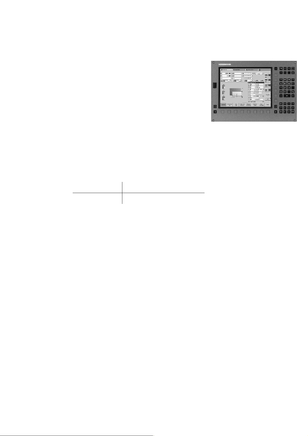
MANU ALplus 620
The Contouring Control for CNC and Cycle Lathes
The MANUALplus 620 for cy cle lathes
Conceived for general repairs, thread repairs, single parts and •
short production runs
Supports action-oriented machining•
Quickly learned—requires minimum training time•
Supports boring, drilling and milling operations on the face and •
lateral surface
Features a wide machining spectrum, from simple turned parts •
to complex workpieces
The MANUALplus 620 for CNC lathes
Conceived for medium-sized and large production r uns•
Programming via smart.Turn and/or DIN PLUS•
smart.Turn is quickly learned and requires v ery little training time•
Supports boring, drilling and milling operations on the face and •
lateral surface
Features a wide machining spectrum, from simple turned parts •
to complex workpieces
30
Page 31

Technical Description
Axes
The MANUALplus 620 is a contouring control f or lathes with one
spindle and a slide (X, Z and Y) for tool movement. The control can
also offset the display of mo v ements in the Z axis with those of its
secondary axis W.
The MANUALplus supports both horizontal and vertical lathes.
Display and
programming
Traverse range –99 999.9999 to +99 999.9999 [mm]
Tool carriers The MANUALplus 620 supports quic k change tool posts (Multifi x)
Feed rate in
mm/min•
mm/revolution•
Feed rate ov erride: 0 to 150%•
Maximum feed rate at f•
60 000 min
No. of pole pairs in motor
The machine tool builder defi nes the traverse range. It is also
possible for the operator to limit the traverse range if he wishes to
reduce the working space (with software limit switches).
A protection zone for the spindle (Z–) can also be specifi ed.
and tool turrets. The tool carriers can be located in front of or
behind the workpiece.
–1
= 5 000 Hz:
PWM
· screw pitch [mm]
C1(S4)
Y1 Z1
31
Page 32

Spindle
For machines featuring a higher le v el of automation, y ou can
position the spindle or switch to C-axis operation.
Display and
programming
Spindle positioning Input resolution and display step: 0.001°
Spindle override 50 to 150%
Maximum speed n
Speed limiting The MANUALplus monitors the actual speed.•
Gear ranges A specifi c parameter can be defi ned for each gear range. The
C-axis operation For milling, drilling and boring cycles, either the spindle is switched
Spindle speed:
Constant shaft speed: 1 to 99 999 rpm•
Constant surface speed: 1 to 9 999 m/min•
max
f
PWM
NPP = number of pole pairs
Speed limiting can be adjusted via parameter and in the feed •
rate/spindle/tool menu.
gears are switched via the PLC. Up to 10 gear ranges are
supported.
to C-axis operation or a separate C-axis drive is activated.
Input resolution and display step: 0.00 1°
NPP · 5 000 Hz
= PWM frequency in Hz
f
· 60 000 min
PWM
=
–1
Driven T ool
The live (i.e. driv en) tool is used f or drilling and tapping holes as
well as for milling in M1 9 or C-axis operation. P rograms f or a driv en
tool can be entered in manual operation, via cycles with smart.Turn
or in the DIN editor .
Display and
programming
Speed limiting The MANUALplus monitors the actual speed.•
Speed of the driven tool:
Constant shaft speed: 1 to 99 999 rpm•
Constant surface speed: 1 to 9 999 m/min•
Speed limiting can be defi ned via parameter and in the feed-rate/•
spindle/tool menu (TSF menu).
32
Page 33

Digital Control
Integrated in v er t er
Servo drive control
Velocity
Nominal
velocity
Nominal
position
feedforward
Position
controller
Position controllers, speed controllers, current controllers and
inverters are integrated in the control. HEIDENHAIN sync hronous
and asynchronous motors are connected to the MANU ALplus 620.
Inverter
Acceleration
Nominal
acceleration
Nominal
speed
feedforward
Speed
controller
Nominal
current
Current
controller
Power stage
Actual current
Actual speed
Motor with
rotary encoder
for shaft speed
and rotor position
Machine
Machine slide
with linear or
angle encoder
Axis feedback
control
Operation with
following er r or
(servo lag)
Servo control with
feedforw ar d
Actual position
The MANUALplus 620 operates with f eedf orward control.
The term “f ollo wing er ror” denotes the distance between the
momentary nominal position and the actual position of the axis.
The velocity is calculated as follows:
v = k
· s
v
a
k
s
v = velocity
= position loop gain
v
= following error
a
Feedforward control means that a velocity and acceleration input
is adapted to the machine while taking the jerk limiting into
account. Together with the values calculated from the f ollo wing
error , it f orms the nominal v alue. This greatly reduces the following
error (to within a few µm).
The feedf orward is adjustable from 0 to 1 00 % via a mac hine
parameter .
33
Page 34

Compensation of
torque r ipples
The torque of synchronous, torque and linear motors is subject to
periodic oscillations, one cause of which can be permanent
magnets. The amplitude of these oscillations depends on the
motor design, and under certain circumstances can have an eff ect
on the workpiece surface. After the axes have been commissioned
with the TNCopt software, the Torque Ripple Compensation (TRC)
of the CC 61 0x or UEC 11x can be used to compensate this torque
ripple.
Control loop
cycle times
CC 6xxx/UEC 11x
Path interpolation
Fine interpolation
Position controller
Speed controller
Current controller
The cycle time for path int erpolation is defi ned as the time
interval during which interpolation points on the path are
calculated. The cycle time for fi ne interpolation is defi ned as the
time interval during which interpolation points are calculated that
lie between the interpolation points calculated for path
interpolation. The cycle time for the position controller is defi ned
as the time interval during which the actual position v alue is
compared to the calculated nominal position value. The cycle time
for the speed controller is defi ned as the time interval during
which the act ual speed v alue is compared to the calculated
nominal speed value. The cycle time for the curr ent contr oller is
defi ned as the time interval during which the actual current v alue
is compared to the calculated nominal current value.
3 ms
0.2 ms
0.2 ms
0.2 ms
0.1 ms at f
PWM
Position
Time
= 5 000 Hz
Fast Machining
Look-ahead
34
The MANUALplus 620 calculates the geometry ahead of time in
order to adjust the feed rate. In this wa y directional changes are
detected in time to accelerate or decelerate the appropriate
NC axes.
Page 35

Jerk Limiting
Jerk
Jerk limiting
Jerk smoothing
The derivative of acceleration is referred to as jerk. A linear c hange
in acceleration causes a jerk step. This jerk causes oscillations that
result in contour damage.
To prevent machine oscillations, the jerk is limited to attain
optimum path control. The MANUALplus 620 produces smooth
surfaces at the highest possible feed rate, and y et k eeps the
contour accurate. The machine manufacturer sets the permissible
tolerance via parameter .
The jerk is smoothed by nominal position value fi lters. The
MANUALplus 620 mac hines smooth surf aces at the highest
possible feed rate. The machine manufact urer sets the permissible
tolerance via parameter .
v
a
j
t
t
t
Mac hine Confi guration
A control must have access to specifi c machine data (e.g. traverse
distances, acceleration, speeds) before it can execute its
programmed instructions. These data are defi ned in machine
parameters. Every machine has its own set of parameters.
Structur ed
organization of
machine parameters
Quick access using
MP numbers
The MANUALplus 620 f eat ures a simplifi ed confi guration editor.
The machine parameters are displa y ed on the control's screen in a
clear tree structure. Mov e through the structure with the operating
panel keys or a USB mouse. The parameters are entered in
windows, similar to a PC.
As an alternative, the confi guration editor can display a table view.
This is especially useful when confi guring the parameter blocks,
since the parameters of all axes are then visible at a glance.
Each machine parameter has a unique 6-digit MP number. The
GOTO function can be used for quic k access to an y machine
parameter .
35
Page 36

Encoders
For speed and position control of the axes and spindle,
HEIDENHAIN off ers both incremental as well as absolute
encoders.
Incremental
encoders
Incremental encoders have as measuring standard a grating
consisting of alternate lines and spaces. Relative mov ement
between the scanning head and the scale causes output of
sinusoidal scanning signals. The measured value is calculated by
counting the signals.
Reference mark When the machine is switc hed on, the machine axes need to
traverse a ref erence mark f or an accurate reference to be
established between measured value and machine position. F or
encoders with distance-coded reference marks, the maximum
travel until automatic ref erence mark e v aluation f or linear encoders
is only 20 mm or 80 mm, depending on the model, or 1 0° or 20°
for angle encoders.
Reference mark
evaluation
The routine for trav ersing the reference marks can also be started
for specifi c axes via the PLC during operation (reactivation of
parked axes).
Output signals Incremental encoders with sinusoidal output signals with
» 1 V
levels are suitable for connection to HEIDENHAIN
PP
numerical controls.
Absolute encoders
With absolute encoders, the position information is contained in
several coded trac ks. Thus, an absolute reference is a v ailable
immediately after switch-on. Reference-mark tra v erse is not
necessary. A dditional incremental signals are output for
highly-dynamic control loops.
EnDat interface The MANUALplus 620 is fi tted with the serial EnDat 2.2 interface
for the connection of absolute encoders.
Note: The EnDat interface on HEIDENHAIN encoders diff ers in its
pin assignment from the interface on Siemens motors with
integrated absolute ECN/EQN rotary encoders. Special adapter
cables are available.
Encoder inputs
Incremental and absolute linear, angle or rotary encoders from
HEIDENHAIN can be connected to all position encoder inputs of
the controller unit.
Incremental and absolute rotary encoders from HEIDENHAIN can
be connected to all speed encoder inputs of the CC controller
unit.
Inputs Signal level/
Interface
1)
Input frequency
1)
Position Rotational
speed
Incremental » 1 V
PP
Absolute EnDat 2.2 / 02
» 1 V
EnDat 2.2
1)
Switc hable
2)
EnDat 2.2 includes EnDat 2.1
PP
2)
36
33 kHz/350 kHz 350 kHz
–
33 kHz/350 kHz–350 kHz
/22 – –
Page 37

Types of Error Compensation
Linear error
Nonlinear error
Backlash
Hysteresis
Reversal peaks
The MANUALplus 620 f eat ures functions f or automatic
compensation of mechanical errors of the machine.
Linear error can be compensated over the entire trav el range f or
each axis.
The MANUALplus 620 compensates for axis er rors and errors that
result from other axes (spindle-pitch er ror, sagging, misaligned
axes, etc.).
The play between table movement and rotary encoder movement
on direction changes can be compensated in length
measurements by spindle and rotary encoder. This backlash is
outside the controlled system.
The hysteresis between table mov ement and motor mo v ement is
also compensated in length measurements. In this case the
hysteresis is within the controlled system.
In circular movements, rev ersal peaks can occur at quadrant
transitions due to mechanical infl uences. T he MANU ALplus 620
can compensate for these reversal peaks.
Stick-slip friction
Sliding friction
Thermal expansion
At very low feed rates, high static friction can cause the slide to
stop and start repeatedly for short periods. This is also known as
stiction. The MANUALplus 620 can compensate for this problem
condition.
Sliding friction is compensated by the speed controller of the
MANUALplus 620.
To compensate thermal expansion, the mac hine's e xpansion
behavior must be known.
The temperature can be recorded via temperature measurement
thermistors connected to the analog inputs of the
MANUALplus 620. The PLC evaluates the temperature information
and transfers the compensation value to the NC.
37
Page 38

Monitoring F unctions
During operation, the MANUALplus 620 monitors:
Amplitude of the encoder signals•
Edge separation of the encoder signals•
Absolute position with encoders with distance-coded •
reference marks
Current position (following error monitoring)•
Actual path trav ersed (mo v ement monitoring)•
Position de viation at standstill•
Nominal speed value•
Checksum of saf ety-related functions•
Supply voltage•
Buff er battery voltage•
Operating temperature of the MC and CPU•
Running time of the PLC program•
Motor current and temperature•
Temperature of pow er module•
DC-link voltage•
With EnDat 2.2 encoders:
CRC checksum of the position value•
EnDat-Alarm Error1 • EnDat status alarm register (0xEE)
EnDat alarm Error2•
Edge speed of 5 µs (monotime)•
Transmission of the absolute position value on the time grid•
In the case of hazardous errors, an EMERGENCY STOP message
is sent to the external electronics via the control-is-ready output,
and the axes are brought to a stop. The correct connection of the
MANUALplus 620 into the mac hine ’s EMERGENCY STOP loop is
checked when the control system is switc hed on. In the e v ent of
an error , the MANU ALplus 620 displa y s a message in plain
language.
Context-sensitive
help
KinematicsDesign
The HELP and ERR keys provide the user with context-sensitive
help. This means that in the event of an error message, the
MANUALplus 620 displays inf ormation on the cause of the er ror
and proposes solutions. The machine manufacturer can also use
this function for PLC error messages.
KinematicsDesign is a PC program for creating adaptable fl exible
kinematic confi gurations. When used with MANU ALplus 620, it
supports:
Complete kinematic confi gurations•
Transfer of confi guration fi les between control and PC•
Activation of dif ferent kinematics confi gurations•
Visualization of transformation c hains•
38
Page 39

Commissioning and Diagnostic Aids
DriveDiag (accessory) The DriveDiag sof tware f or PCs permits a simple and f ast
TNCopt (accessory) PC software for commissioning digital control loops
The MANUALplus 620 provides comprehensiv e, internal
commissioning and diagnostic aids. In addition, highly eff ectiv e
PC software for diagnosis, optimization and remote control is
available.
diagnosis of the drives. It also makes it possible to display and
evaluate the electronic ID labels.
The following diagnostic functions are a v ailable:
Reading and displaying the electronic ID labels of QS Y motors •
with EQN 13xx or ECN 13xx
Reading and displaying the electronic ID labels of the UVR 1xx D •
and UM 1xx D inverter modules
Displaying and evaluating the internal control conditions and the •
status signals of the inverter components
Displaying the analog values av ailable to the driv e controller•
Automatic test for proper function of motors and inv erters•
Automatic test of position and speed encoders•
Functions:
Commissioning the current controller•
(Automatic) commissioning of the speed controller•
(Automatic) optimization of sliding-friction compensation•
(Automatic) optimization of the reversal-peak compensation•
(Automatic) optimization of kV factor•
Circular interpolation test, contour test•
Requirements DriveDiag and TNCopt place the following demands on the PC:
Windows 2000/XP/Vista/7 operating system•
At lease VGA—XGA recommended•
At least 16 MB RAM•
At least 15 MB of free hard-disk space•
Serial or Ethernet interface•
DriveDiag and TNCopt for MANUALplus 620 are available for
downloading as PC software from the HEIDENHAIN “HESIS-Web
Including Filebase “ on the Internet.
OLM
Online monitor
The online monitor (OLM) supports the commissioning and
diagnosis of control components through:
Display of control-internal variables for ax es and channels•
Display of controller-internal variables (if a CC is present)•
Display of hardware signal states•
Various trace functions•
Activation of spindle commands•
Enabling control-internal debug outputs•
The online monitor is a component part of the MANUALplus 620
and is called over a code number.
39
Page 40

Oscilloscope
Logic signals Simultaneous graphic representation of the logic states of
The MANUALplus 620 f eat ures an integrated oscilloscope. B oth
X/t and X/Y graphs are possible. The following characteristic curves
can be recorded and saved in six c hannels:
Actual value of axis feed rate•
Nominal value of axis feed rate•
Contouring feed rate•
Actual position•
Nominal position•
Following error of the position controller•
Nominal values for speed, acceleration and jerk•
Actual values f or speed, acceleration and jerk•
Content of PLC operands•
Encoder signal (0° – A)•
Encoder signal (90° – B)•
Diff erence between position and speed encoder•
Nominal velocity value•
Integral-action component of the nominal current value•
Torque-determining nominal current value•
up to 16 operands (markers, w ords, inputs, outputs, counters,
timers)
Marker (M)•
Input (I)•
Output (O)•
Timer (T)•
Counter (C)•
IpoLogik (X)•
TNCscopeNT
(accessory)
API DATA
Table function
Trace function
Log
TeleService
(accessory)
PC software for transferring the oscilloscope fi les to the PC.
Note: The trace fi les are saved in the TNCscopeNT data format.
The API DATA function enables the control to display the states or
contents of the symbolic API markers and API double w ords. This
function requires that your PLC program use the new symbolic
memory interface.
The current conditions of the markers, words, inputs, outputs,
counters and timers are displayed in tables. The conditions can be
changed through the ke yboard.
The current content of the operands and the accumulators is
shown in the instruction list in each line in HEX or decimal code.
The active lines of the instruction list are mark ed.
For the purposes of error diagnosis, there is one log for all er ror
messages and one for all key strok es.
PC software for remote diagnosis, remote monitoring, and remote
control of the MANUALplus 620. For further inf ormation, ask f or
the Remote Diagnosis with TeleService T echnical Information
sheet.
40
Page 41

Integral PLC
The PLC program is created by the mac hine manuf acturer either
with the PLC development sof tware PLCdesignNT (accessory) or
at the control with an external PC keyboard with a USB connection.
Machine-specifi c functions are activated and monitored through
the PLC inputs/outputs. The number of PLC inputs/outputs
required depends on the complexity of the machine.
PLC inputs/outputs
PLC programming
PLC inputs and outputs are available via the external PL 6xxx
PLC input/output systems or the UEC 11 .
The PLC inputs/outputs and the PROFIBUS-DP -capable input/
output system must be confi gured with the PC software IOconfi g.
Format Statement list
Memory 50 MB
Cycle time 21 ms, adjustable
Instruction set • Bit, byte and word commands
• Logical operations
• Arithmetic commands
• Comparisons
• Nested calculations (parentheses)
• Jump commands
• Subroutines
• Stack operations
• Submit Programs
• 952 timers
• 48 counters
• Comments
• PLC modules
• 100 strings
PLC soft ke ys
PLC positioning
PLC axes
The machine manuf acturer can display his own PLC sof t keys in
the vertical soft-k e y ro w on the screen.
All closed-loop axes can be also positioned through the PLC.
PLC-positioning of the NC-axes cannot be superimposed on
NC positioning.
Axes can be controlled by the PLC. They are programmed by
M-functions or OEM cycles. The PLC axes are positioned
independently of the NC axes.
41
Page 42

PLCdesignNT
(accessory)
PC software for PLC program de v elopment.
PLCdesignNT can be used to easily create PLC programs.
Comprehensive examples of PLC programs are included.
Functions:
Easy-to-use text editor•
Menu-guided operation•
Programming of symbolic operands•
Modular programming method•
"Compiling" and "linking" of PLC source fi les•
Operand commenting, creation of a documentation fi le•
Comprehensive help system•
Data transfer between the MANUALplus 620 and the PC•
Creation of PLC soft keys•
PC requirements:
Windows 2000/XP/Vista/7 operating system•
Compatible computer , Pentium 133 or higher•
At least 32 MB RAM•
At least 20 MB free memory on the hard disk•
At least VGA•
Serial interface; Ethernet interface recommended•
Internet Explorer 4.0 1 or higher•
PLC basic program
The PLC basic program serves as a basis for adapting the
MANUALplus 620 to the requirements of the respective machine.
Registered customers can download it from the Internet.
The following functions are co v ered b y the PLC basic program:
Controlling all axes•
Positioning the ax es after the reference run•
Clamped axes•
Homing the axes, reference end positions•
Compensating the axis temperature•
Feed rate control•
Controlling and orienting the spindle•
Spindle brake•
Gear switching via M functions•
C axis via main drive•
C axis via separate drive•
1)
PLC soft keys•
Displaying and managing PLC error messages•
Hydraulic control•
Hydraulic chuck•
Electronic handwheels•
Controlling the coolant system•
Handling of M and G functions•
Lubrication•
Chip conveyor•
Door control•
Tool change f or Multifi x (quick change tool holder)•
Positioning of the tool t urret with three-phase motor•
1)
Basic functions are implemented
1)
1)
1)
1)
1)
1)
1)
1)
42
Page 43

Data Interfaces
The MANUALplus 620 is connected to PCs, networks and other
data storage devices via data interfaces.
Ethernet
Protocol The MANUALplus 620 communicates using the TCP/IP protocol.
Network connection NFS fi le server•
Data transfer rate Approx. 40 to 80 Mbps (depending on fi le type and network
RS-232-C/V.24
Data transfer rate 115 200; 57 600; 38 400; 19 200;
Protocols The MANU ALplus 620 can transfer data using various protocols.
Standard
data transfer
Blockwise
data transfer
The MANUALplus 620 can be interconnected via the Ethernet
interface. The MANUALplus 620 features a 100BaseT Ethernet
(Twisted Pair Ethernet) connection to the data network.
Maximum transmission distance:
Unshielded 100 m
Shielded 400 m
Windows networks (SMB)•
utilization)
Data interface according to DIN 66 020 or EIA standard RS-232-C.
Maximum transmission distance: 20 m
The RS-232-C/V.24 interface can be addressed only by the PLC.
9 600; 4 800; 2 400; 1 200; 600; 300; 150; 110 bits per second
The data is transferred character by character. T he number of data
bits, stop bits, the handshake and character parity must be set by
the user .
The data is transferred blockwise. A block check character (BCC) is
used to ensure data integrity. This method improves data security.
LSV2 Bidirectional transf er of commands and data according to
DIN 66 01 9. The data is divided into blocks and transf er red.
Adapter block For connecting the interface to the electrical cabinet or
operating panel.
RS-232-C/V.24 adapter 9-pin ID 363 987-02
25-pin ID 310 085-01
USB
USB hub
Cover The USB hub can be installed in the operating panel in such a way
The MC 6110 feat ures three USB 2.0 interf aces f or the connection
of standard USB devices, such as the mouse, drives, etc. Two are
on the back of the control. One USB interface is on the front and
stays accessible when the control is installed. A cover protects it
from contamination. The USB interfaces are rated for a maximum
supply current of 0.5 A. The maximum cable length for external
USB devices is 5 m without an amplifi er. For lengths of 6 m and
greater , USB connecting cables with integrated amplifi er are
required.
If you need further USB ports or if the supply current is not
suffi cient, a USB hub is required. The USB hub from HEIDENHAIN
off ers f our free USB ports.
Po w er supply: 24 V– / max. 300 mA
ID 582 884-01
that two USB ports can be accessed from the outside. An
optionally available cov er can be used to protect the ports from
contamination.
ID 508 921-01
43
Page 44

Sof tware f or Data Transfer
TNCremoNT
(accessory)
TNCremoPlus
(accessory)
This PC software package helps the user to transfer data from the
PC to the MANUALplus 620. The software on the PC carries out
block-wise data transfer with block check c haracter (BCC).
Functions:
Data transfer (also blockwise)•
Remote control (only serial)•
Management of the MANUALplus 620 fi les•
Backup of the MANUALplus 620 data•
Reading out the log•
Print-out of screen contents•
Text editor•
Managing more than one machine (TNCremoNT)•
Requirements:
Windows 98/98SE/NT4.0/2000/XP/Vista/7 operating system•
At least VGA•
At least 16 MB RAM•
At least 1 0 MB free memory on the hard disk•
Serial or Ethernet interface•
In addition to the features y ou are already f amiliar with from
TNCremoNT, TNCremoPlus can also transfer the current content of
the control’s screen to the PC (“live screen ”). This makes it very
simple to monitor the machine.
ID 340 447-xx
44
Page 45

Mounting Instr uctions
Installation
Mounting and
electrical installation
Degrees of
protection
Electromagnetic
compatibility
Intended place of
operation
When installing the MANUALplus 620, take note of the minimum
spacing, space needed for servicing, and the appropriate length
and location of the connecting cables.
Keep the following in mind during mounting and electrical
installation:
National regulations for power installations•
Interference and noise immunity•
Conditions of operation•
Mounting attit ude•
The following components fulfi ll the requirements for IP 54
(dust protection and splash-proof protection):
MANUALplus 620 (when properly installed)•
Machine operating panel (when properly installed)•
Handwheel•
The unit fulfi lls the requirements for a Class A device in
accordance with the specifi cations in EN 55 022, and is intended
for use in industrially zoned areas.
Protect your equipment from interf erence b y observing the rules
and recommendations specifi ed in the Technical Manual.
Leave space f or
air circulation and servicing!
20
Air out
25
Likely sources of
interference
Protective measures Keep a minimum distance of 20 cm from the MANUALplus 620 •
Interference is mainly produced by capacitiv e and inductiv e
coupling from electrical conductors or from device inputs/outputs,
such as:
Strong magnetic fi elds from transformers or electric motors•
Relays, contactors and solenoid valv es•
High-frequency equipment, pulse equipment and stray magnetic •
fi elds from switch-mode pow er supplies
Po w er lines and leads to the abo v e equipment•
and its leads to devices that carry interference signals.
Keep a minimum distance of 1 0 cm from the MANU ALplus 620 •
and its leads to cables that carry interference signals. For cables
in metallic ducting, adequate decoupling can be achieved by
using a grounded separation shield.
Shielding according to EN 50 178•
Use potential compensating lines with a cross section of 6 mm•
Use only genuine HEIDENHAIN cables, connectors and •
couplings.
25
Supply air
2
45
Page 46

Over all Dimensions
MC 611 0 T
Dimensions in mm
Tolerancing ISO 8015
ISO 2768 - m H
< 6 mm: ±0.2 mm
8
410
386±0.2
12
98+1
5+1
350
332±0.2
274±0.2 2
7
15x45°
0.5
m
386±0.2
270+1
f
¬ 5.5
4x M5
f = Cutout in machine panel
m = Mounting surface
¬ 10
1
¬ 8+1
46
f
400+1
Page 47

MB 620 T
Dimensions in mm
Tolerancing ISO 8015
ISO 2768 - m H
< 6 mm: ±0.2 mm
12
0
34.5
410
386±0.2
+1
56
0
8
M5
+1
49
0
79
94±0.2
76.50
X
+0.5
94
–0.3
f
386±0.5
f
394±0.2
12x45°
¬ 5.5
M5
m
110
94±0.2
0
+1
¬ 8
2.2
0
0
+0.4
24.1
f = Cutout in machine panel
m = Mounting surface
+0.4
X (2x)
2:1
1
4
¬ 22.3
¬ 10
+0.4
0
47
Page 48

CC 6106
Dimensions in mm
Tolerancing ISO 8015
ISO 2768 - m H
< 6 mm: ±0.2 mm
24.75
74.5+0.5
25
¬ 5.5
¬ 12
480
7
456+5
30420
280.5
22.5+1
48
Page 49

CC 6108
Dimensions in mm
Tolerancing ISO 8015
ISO 2768 - m H
< 6 mm: ±0.2 mm
24.75
CC 61 08: 8 control loops
CC 611 0: 10 control loops
99.5+0.5
50±0.2
¬ 5.5
7
¬ 12
30
280.5
22.5+1
480
456+5
420
49
Page 50

UEC 111, UEC 11 2
Dimensions in mm
Tolerancing ISO 8015
ISO 2768 - m H
< 6 mm: ±0.2 mm
480
7
456+5
¬ 5.5
¬ 12
430
5.5
100±0.2 24.75+0.5
149.5
284.5
280.5
PSL 1 30
Dimensions in mm
Tolerancing ISO 8015
ISO 2768 - m H
< 6 mm: ±0.2 mm
M4
M5
300+1
280+1
¬ 12
¬ 5.5
7
30162
10
85.1
212
M6
B
198±0.2
5.5
24.75
50
49
234.9
Page 51

PSL 1 35
Dimensions in mm
Tolerancing ISO 8015
ISO 2768 - m H
< 6 mm: ±0.2 mm
480
30
456±0.2
420
24.75
¬ 12
¬ 5.5
5.5
0
73.4
170.9
335.6
7
10
280.5+1
303+1
M4
M5
PL 6xxx
Dimensions in mm
Tolerancing ISO 8015
ISO 2768 - m H
< 6 mm: ±0.2 mm
51
PL 6x04: 139, PL 6x06: 183, PL6x08: 227
2.75
136
119
100 100
132
148
51
Page 52

PLB 600 1
Dimensions in mm
Tolerancing ISO 8015
ISO 2768 - m H
< 6 mm: ±0.2 mm
48
39.9
24
¬7
3.4
288.4
295±0.3
304
6
133
109.5
52
Page 53

HR 1 30, HR 150, HR 180 with Control Knob
Dimensions in mm
Tolerancing ISO 8015
ISO 2768 - m H
< 6 mm: ±0.2 mm
e
C
¬ 36f8
¬ 0.08 B
B
e
0.01
0.02
¬ 10
0.08 A
0.03 A
20±0.5
36.7±0.5
10
A
¬ 6
4.4
¬ 56
¬ 58
3x 120°
¬ 48
3xM3 x 5
¬ 0.25 C
53
Page 54

HRA 11 0
Dimensions in mm
Selection Switch
Dimensions in mm
Tolerancing ISO 8015
ISO 2768 - m H
< 6 mm: ±0.2 mm
32
24.1
8
2x M 2.5 x 5
SW 14
20 max.
¬ 60.03
Tolerancing ISO 8015
ISO 2768 - m H
< 6 mm: ±0.2 mm
26
M 10
2.6+0.1
12.8+0.3
39
10.1+0.1
54
Page 55

HR 410
Dimensions in mm
Tolerancing ISO 8015
ISO 2768 - m H
< 6 mm: ±0.2 mm
Adapter Cable f or HR 410
Dimensions in mm
Tolerancing ISO 8015
ISO 2768 - m H
< 6 mm: ±0.2 mm
M5
¬ 55
Mounting opening for wall thic kness S†4 Mounting opening for wall thic kness S>4
44
¬ 34
38
32x15
14
Ø 36
32
44
64
19
M4
23
4
¬ 5.5
S
¬ 37
S
55
Page 56

Line Drop Compensator for Encoders with EnDat Interf ace
Dimensions in mm
Tolerancing ISO 8015
ISO 2768 - m H
< 6 mm: ±0.2 mm
34
12.5
¬ 9
¬ 5
58
29
64
36
46
20
RS-232-C/V.24 Adapter
Dimensions in mm
Tolerancing ISO 8015
ISO 2768 - m H
< 6 mm: ±0.2 mm
*)
15
127
*)
Connection to KTY
32
56
Opening for
mounting the
adapter
Page 57

USB Hub
Dimensions in mm
Tolerancing ISO 8015
ISO 2768 - m H
< 6 mm: ±0.2 mm
M3
50
17.5
Cover (accessory)
28
40
68
37
¬ 3.4
109
100±0.2
A
93.2
A
180°
m
¬ 3.5
17.5
30±0.2
= Cutout for mounting
m
80
70±0.2
50±0.2
¬ 2.5
19
42
60±0.2
USB Extension Cable with Hubs
Dimensions in mm
Tolerancing ISO 8015
ISO 2768 - m H
< 6 mm: ±0.2 mm
L
n x 5000 50001000...5000
USBA USBB
¬ 20
n = 0 ... 4
L = Ordering length
115
57
Page 58

Cuboid Probe Contact for TT 1 40
Dimensions in mm
Tolerancing ISO 8015
ISO 2768 - m H
< 6 mm: ±0.2 mm
13.6
TT 1 40
0.01 A
7.5
¬ 20
¬ 40
0.1
¬ 34
¬ 20
7. 5
¬ 10
0
0.03 A
4.2
¬ 25
21.5
21.5
¬ 25
¬ 20
7.5
4.2
58
¬ 29.5
97
1x45°
13
18
A
¬ 43
¬ 48
0.2
0
21
70.9
37
6.7
M12
19±0.1
13
¬ 13.5
¬ 20
¬ 30
¬ 65
1
97
30.7
Dimensions in mm
Tolerancing ISO 8015
ISO 2768 - m H
< 6 mm: ±0.2 mm
Page 59

Documentation
Technical
documentation
User documentation
Other
documentation
MANUALplus 620• Technical Manual ID 634 863-xx
in English or German
Invert er S yst ems and Mot ors•
Technical Manual ID 208 962-xx
MANUALplus 620• User's Manual ID 634 864-xx
MANUALplus 620 •
smart.Turn and DIN programming ID 685 556-xx
Miscellaneous
TNCremo• User's Manual As integrated help and in PDF format
TNCremoNT• User's Manual As integrated help and in PDF format
TNCremoPlus• User's Manual As integrated help and in PDF format
PLCdesign• User's Manual As integrated help and in PDF format
IOconfi g• User's Manual As integrated help and in PDF format
MANUALplus 620• brochure ID 634 865-xx
Touch Probes• brochure ID 208 951-xx
Invert er S yst ems• brochure ID 622 420-xx
• Motors brochure ID 208 893-xx
Product Overview•
Remote Diagnosis with TeleService ID 348 236-xx
Touch Probes• CD-ROM ID 344 353-xx
DataPilot MP/CP 620 • CD-R OM
Demo version In preparation
59
Page 60

HEIDENHAIN Service
Technical support
Replacement
control system
Hotline
HEIDENHAIN off ers the machine manufacturer technical support
to optimize the adaptation of the MANUALplus to the mac hine—
including on-site support.
In the event of a fault, HEIDENHAIN guarantees the rapid supply
of a replacement control system (usually within 24 hours in
Europe).
Our service engineers are naturally at your disposal by telephone if
you have an y questions on the interf acing of the control or in the
event of faults.
TNC support { +49 8669 31-3101
E-mail: service.nc-support@heidenhain.de
PLC programming { +49 8669 31-3102
E-mail: service.plc@heidenhain.de
NC programming { +49 8669 31-3103
E-mail: service.nc-pgm@heidenhain.de
Measuring systems { +49 8669 31-3104
E-mail: service.ms-support@heidenhain.de
Lathe controls { +49 8669 31-3105
E-mail: service.lathe-support@heidenhain.de
Seminars
HEIDENHAIN provides technical customer training in the
following subjects:
NC programming•
PLC Programming•
MANUALplus 620 mounting and commissioning•
MANUALplus 620 service•
Encoder service•
Special training for specifi c customers•
For more information on dates, registration, etc. call in German y:
{ 08669 31-2293 or 31-1695
| 08669 31-1999
E-mail: mtt@heidenhain.de
www .heidenhain.de
60
Page 61

Subject Index
A
Absolute encoders ............................. 36
Accessories .......................................... 8
API DATA ............................................ 40
Axes ................................................... 31
B
Basic modules ................................... 19
C
Cable overview .................................. 26
C-axis operation ................................. 32
CC 61 0x .............................................. 17
CC 61 06......................................... 1 7, 48
CC 61 08......................................... 1 7, 49
CFR .................................................... 16
CFR CompactFlash ............................ 16
Commissioning and diagnostic aids .. 39
Compensation of torque ripples ........ 34
Conductor bars .................................. 20
Context sensitive help ....................... 38
Controller unit .................................... 17
D
Data interfaces ................................... 43
Digital control ..................................... 33
Digital Control Design ........................ 13
Documentation .................................. 59
DriveDiag............................................ 39
Driven tool .......................................... 32
E
Electromagnetic compatibility ........... 45
Electronic handwheels ...................... 22
Encoders ............................................ 36
Error compensation ........................... 37
Ethernet ............................................. 43
Expansion PL ..................................... 19
H
HR 130 ......................................... 22, 53
HR 150 ......................................... 22, 53
HR 180 ......................................... 22, 53
HR 41 0 ......................................... 23, 55
HRA 11 0 ....................................... 22, 54
HSCI ................................................... 13
HSCI adapter ...................................... 21
I
Incremental encoders....................... 36
Integral PLC ....................................... 41
IOconfi g software for PCs ................. 18
I/O modules ....................................... 19
J
Jerk ..................................................... 35
Jerk limiting ........................................ 35
Jerk, smoothed .................................. 35
K
KinematicsDesign .............................. 38
L
Log ..................................................... 40
Look-ahead ......................................... 34
M
Machine confi guration ....................... 35
Machine operating panel ................... 21
Main computer .................................. 15
MANUALplus 620 ......................... 2, 14
Master keyword ................................. 16
MB 620 T ............................................ 21
MC 611 0 T ..................................... 15, 46
Monitoring functions ......................... 38
Mounting instructions ........................ 45
N
NC software license .......................... 16
O
Online monitor ................................... 39
Options......................................... 12, 15
Oscilloscope....................................... 40
P
PL 6xxx......................................... 19, 51
PLB 6001 ...................................... 21, 52
PLC basic program ............................ 42
PLCdesignNT ..................................... 42
PLC input/output systems ................. 19
PLC inputs/outputs ............................ 41
PLC Programming ............................. 41
Po wer supply f or HSCI components .. 20
Probe contact, cuboid ........................ 24
PSL 130 ........................................ 20, 50
PSL 135 ........................................ 20, 51
R
RS-232-C/V.24 .................................... 43
S
Secondary axes ................................. 16
Seminars ............................................ 60
SIK component .................................. 16
Snap-on keys ...................................... 25
Software for data transf er .................. 44
Spindle ............................................... 32
System PL .......................................... 19
T
Table function ..................................... 40
TeleService ......................................... 40
TNCopt ............................................... 39
TNCremoNT ....................................... 44
TNCremoPlus .................................... 44
TNCscopeNT ..................................... 40
Tool carrier .......................................... 31
Touch probes ...................................... 24
Trace function..................................... 40
TS 220 ................................................ 24
TS 440 ................................................ 24
TS 444 ................................................ 24
TS 640 ................................................ 24
TS 740 ................................................ 24
TT 140 ................................................ 24
U
UEC 11x ............................................. 18
UEC 111 ........................................ 18, 50
UEC 112 ....................................... 18, 50
Uniformly digital ................................. 13
USB .................................................... 43
USB hub ....................................... 43, 57
User functions ..................................... 9
W
Workpiece measurement .................. 24
61
Page 62

DR. JOHANNES HEIDENHAIN GmbH
Dr.-Johannes-Heidenhain-Straße 5
83301 Traunreut, Germany
{ +49 8669 31-0
| +49 8669 5061
E-mail: info@heidenhain.de
www.heidenhain.de
Vollständige und weiter e Adressen siehe www .heidenhain.de
For complete and further addr esses see www.heidenhain.de
DE HEIDENHAIN Technisches Büro Nord
12681 Berlin, Deutschland
{ 030 54705-240
HEIDENHAIN Technisches Büro Mitte
08468 Heinsdorfergrund, Deutschland
{ 03765 69544
HEIDENHAIN Technisches Büro West
44379 Dortmund, Deutschland
{ 0231 618083-0
HEIDENHAIN Technisches Büro Südwest
70771 Leinfelden-Ec hterdingen, Deutschland
{ 0711 993395-0
HEIDENHAIN Technisches Büro Südost
83301 T raunreut, Deutschland
{ 08669 31-1345
AR NAKASE SRL.
B1653AO X Villa Ballester, Argentina
www.heidenhain.com.ar
AT HEIDENHAIN Techn. Büro Österr eic h
83301 T raunreut, Germany
www.heidenhain.de
AU FCR Motion Technology Pty. Ltd
Laverton North 3026, A ustralia
E-mail: vicsales@fcrmotion.com
BA Bosnia and Herzegovina − SL
BE HEIDENHAIN NV/SA
1760 Roosdaal, Belgium
www.heidenhain.be
BG ESD Bulgaria Ltd.
Sofi a 1172, Bulgaria
www.esd.bg
BR DIADUR Indústria e Comércio Ltda.
04763-070 – São Paulo – SP, Brazil
www.heidenhain.com.br
BY Belarus
GERTNER Service GmbH
50354 Huerth, Germany
www.gertner.biz
CA HEIDENHAIN CORPORATION
Mississauga, OntarioL5T2N2, Canada
www.heidenhain.com
CH HEIDENHAIN (SCHWEIZ) AG
8603 Schwerzenbach, Switzerland
www.heidenhain.ch
CN DR. JOHANNES HEIDENHAIN
(CHINA) Co., Ltd.
Beijing 1 01312, China
www.heidenhain.com.cn
CZ HEIDENHAIN s.r.o.
102 00 Praha 10, Czech Republic
www.heidenhain.cz
DK TP TEKNIK A/S
2670 Greve, Denmark
www.tp-gr uppen.dk
ES FARRESA ELECTRONICA S.A.
08028 Barcelona, Spain
www.f ar resa.es
FI HEIDENHAIN Scandinavia AB
02770 Espoo, Finland
www.heidenhain.fi
FR HEIDENHAIN FRANCE sarl
92310 Sèvres, France
www.heidenhain.fr
GB HEIDENHAIN (G.B.) Limited
Burgess Hill RH15 9RD , United Kingdom
www.heidenhain.co.uk
GR MB Milionis Vassilis
17341 Athens, Greece
www.heidenhain.gr
HK HEIDENHAIN LTD
Kowloon, Hong Kong
E-mail: service@heidenhain.com.hk
HR Croatia − SL
HU HEIDENHAIN Kereskedelmi Képviselet
1239 Budapest, Hungary
www.heidenhain.hu
ID PT Servitama Era Toolsindo
Jakarta 13930, Indonesia
E-mail: ptset@group.gts.co.id
IL NEUMO VARGUS MARKETING LTD .
Tel Aviv 61570, Israel
E-mail: neumo@neumo-vargus.co.il
IN HEIDENHAIN Optics & Electronics
India Privat e Limit ed
Chennai – 600 031, India
www.heidenhain.in
IT HEIDENHAIN ITALIANA S.r.l.
20128 Milano, Italy
www.heidenhain.it
JP HEIDENHAIN K.K.
Tokyo 194-021 5, J apan
www.heidenhain.co.jp
KR HEIDENHAIN Korea LTD.
Gasan-Dong, Seoul, Korea 153-782
www.heidenhain.co.kr
ME Montenegro − SL
MK Macedonia − BG
MX HEIDENHAIN CORPORA TION MEXICO
20235 Aguascalientes, Ags., Mexico
E-mail: info@heidenhain.com
MY ISOSERVE Sdn. Bhd
56100 Kuala Lumpur, Malaysia
E-mail: isoserve@po.jaring.my
NL HEIDENHAIN NEDERLAND B.V.
6716 BM Ede, Netherlands
www.heidenhain.nl
NO HEIDENHAIN Scandinavia AB
7300 Orkanger, Norway
www.heidenhain.no
PH Machinebanks` Corporation
Quezon City, Philippines 11 13
E-mail: info@machinebanks.com
PL APS
02-489 Warszawa, Poland
www.apserwis.com.pl
PT FARRESA ELECTRÓNICA, LDA.
4470 - 177 Maia, Portugal
www.f ar resa.pt
RO HEIDENHAIN Reprezentant¸a˘ Romania
Bras¸ov, 500338, Romania
www.heidenhain.ro
RS Serbia − BG
RU OOO HEIDENHAIN
12531 5 Mosco w, Russia
www.heidenhain.r u
SE HEIDENHAIN Scandinavia AB
12739 Skärholmen, Sw eden
www.heidenhain.se
SG HEIDENHAIN P A CIFIC PTE LTD.
Singapore 408593
www.heidenhain.com.sg
SK KOPRETINA TN s.r.o.
91 10 1 T rencin, Slovakia
www.k opretina.sk
SL Posredništvo HEIDENHAIN
NA VO d.o.o.
2000 Maribor, Slovenia
www.heidenhain-hubl.si
TH HEIDENHAIN (THAILAND) LTD
Bangkok 10250, Thailand
www.heidenhain.co.th
TR T&M Mühendislik San. ve Tic. LTD. S¸TI·.
34728 Ümraniye-Istanbul, Turkey
www.heidenhain.com.tr
TW HEIDENHAIN Co., Ltd.
T aichung 40768, Taiw an R.O.C.
www.heidenhain.com.tw
UA Gertner Service GmbH Büro Kiev
01133 Kiev, Ukraine
www.gertner.biz
US HEIDENHAIN CORPORATION
Schaumburg, IL 60173-5337, USA
www.heidenhain.com
VE Maquinaria Diekmann S.A.
Caracas, 1040-A, Venezuela
E-mail: purchase@diekmann.com.ve
VN AMS Co. Ltd
HCM City, Vietnam
E-mail: davidgoh@amsvn.com
ZA MAFEMA SALES SERVICES C.C.
Midrand 1685, South Africa
www.heidenhain.co.za
Zum Abhef t en hier falzen! / Fold here f or fi ling!
743 682-21 · 5 · 8/2010 · H · Printed in Germany
 Loading...