


harman/kardon
hk3370/3470
STEREO RECEIVER
PRELIMINARY
SERVICE MANUAL
CONTENTS
ESD WARNING……………………..…….…….2 LEAKAGE TESTING………………..…….…....3 BASIC SPECIFICATIONS hk3370………..…..4 BASIC SPECIFICATIONS hk3470………..…..5 FRONT PANEL CONTROLS hk3370.….…….6 REAR PANEL CONNECTIONS hk3370…..…8 REMOTE CONTROL FUNCTIONS HK3370..10 FRONT PANEL CONTROLS hk3470.……….12 REAR PANEL CONNECTIONS hk3470…..…15 REMOTE CONTROL FUNCTIONS HK3470..17 TROUBLESHOOTING GUIDE…...….….....…19 ALIGNMENT PROCEDURES…………….…..20 WAVEFORMS……………………………..…..23
BLOCK DIAGRAM…………..………………28 EXPLODED VIEW HK3370………….……..29 EXPLODED VIEW HK3470…….……...…..30 DISASSEMBLY PROCEDURES…………..31 MECHANICAL PARTS LIST HK3370.……39 ELECTRICAL PARTS LIST HK3370.….…40 MECHANICAL PARTS LIST HK3370.……57 ELECTRICAL PARTS LIST HK3370.….…58 IC DESCRIPTIONS………………….……..75 PCB DRAWINGS……………………...……86 SCHEMATICS………………….……………92 WIRING DIAGRAM………………………...103 PACKAGE………………….………………..104
harman/kardon, Inc. 250 Crossways Park Dr.
Woodbury, New York 11797

Some semiconductor (solid state) devices can be damaged easily by static electricity. Such components commonly are called Electrostatically Sensitive (ES) Devices. Examples of typical ES devices are integrated circuits and some field effect transistors and semiconductor "chip" components.
The following techniques should be used to help reduce the incidence of component damage caused by static electricity.
1.Immediately before handling any semiconductor component or semiconductor-equipped assembly, drain off any electrostatic charge on your body by touching a known earth ground. Alternatively, obtain and wear a commercially available discharging wrist strap device, which should be removed for potential shock reasons prior to applying power to the unit under test.
2.After removing an electrical assembly equipped with ES devices, place the assembly on a conductive surface such as aluminum foil, to prevent electrostatic charge build-up or exposure of the assembly.
3.Use only a grounded-tip soldering iron to solder or unsolder ES devices.
4.Use only an anti-static solder removal device. Some solder removal devices not classified as "anti-static" can generate electrical charges sufficient to damage ES devices.
5.Do not use freon-propelled chemicals. These can generate electrical change sufficient to damage ES devices.
6.Do not remove a replacement ES device from its protective package until immediately before you are ready to install it. (Most replacement ES devices are packaged with leads electrically shorted together by conductive foam, aluminum foil or comparable conductive material.)
7.Immediately before removing the protective material from the leads of a replacement ES device, touch the protective material to the chassis or circuit assembly into which the device will be installed.
CAUTION : Be sure no power is applied to the chassis or circuit, and observe all other safety precautions.
8.Minimize bodily motions when handling unpackaged replacement ES devices. (Otherwise harmless motion such as the brushing together or your clothes fabric or the lifting of your foot from a carpeted floor can generate static electricity sufficient to damage an ES devices.
Each precaution in this manual should be followed during servicing.
Components identified with the IEC symbol in the parts list are special significance to safety. When replacing a component identified with
  , use only the replacement parts designated, or parts with the same ratings or resistance, wattage, or voltage that are designated in the parts list in this manual. Leakage-current or resistance measurements must be made to determine that exposed parts are acceptably insulated from the supply circuit before retuming the product to the customer.
2
Before returning the unit to the user, perform the following safety checks :
1. Inspect all lead dress to make certain that
leads are not pinched or that hardware is not
lodged between the chassis and other metal
parts in the unit.
2. Be sure that any protective devices such as
nonmetallic control knobs, insulating fish-
papers, cabinet backs, adjustment and
compartment covers or shields, isolation
resistor-capacity networks, mechanical
insulators, etc. Which were removed for the
servicing are properly re-installed.
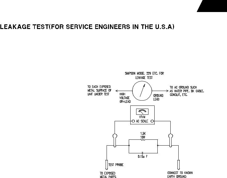
3. Be sure that no shock hazard exists ; check for leakage
current using Simpson Model 229 Leakage Tester, standard
equipment item No. 21641, RCA Model WT540A or use
alternate method as follows : Plug the power cord directly
Into a 120 volt AC receptacle (do not use an Isolation
Transformer for this test). Using two clip leads, connect a
1500 ohms, 10watt Resistor paralleled by a 0.15uF capacitor, in series with all exposed metal cabinet parts and a known earth ground, such
as a water pipe or conduit. Use a VTVM or VOM with 1000 ohms per volt, or higher sensitivity to measure the AC voltage drop across the
resistor. (See diagram) Move the resistor connection to each exposed metal part having a return path to the chassis (antenna, metal,
cabinet, screw heads, knobs and control shafts, escutcheon, etc.) and measure the AC voltage drop across the resistor. (This test should be
performed with the 0.35 volt RMS or more is excessive and indicates a potential shock hazard which must be corrected before returning the
unit to the owner.
3

hk3370
Technical Specifications
Audio Section
Stereo Mode
Continuous Average Power (FTC)
70 Watts per channel, 20Hz–20kHz
@< 0.07% THD, both channels driven into 8 ohms 95 Watts per channel, 20Hz–20kHz
@< 0.2% THD, both channels driven into 4 ohms
Input Sensitivity/Impedance |
|
Linear (High Level) |
200mV/47kohms |
Signal-to-Noise Ratio (IHF-A) |
95dB |
Frequency Response |
|
@ 1W (+0dB, –3dB) |
10Hz– 110kHz |
High Instantaneous |
|
Current Capability (HCC) |
±42 Amps |
Transient Intermodulation |
|
Distortion (TIM) |
Unmeasurable |
Rise Time |
16 µsec |
Slew Rate |
40V/µsec |
Depth measurement includes knobs, buttons and terminal connections. Height measurement includes feet and chassis.
All features and specifications are subject to change without notice. Harman Kardon is a registered trademark, and Power for the digital revolution is a trademark, of Harman Kardon, Inc.
FM Tuner Section
Frequency Range |
87.5 –108MHz |
Usable Sensitivity |
IHF 1.12 µV/13.5dBf |
Signal-to-Noise Ratio |
Mono/Stereo 73/72dB |
Distortion |
Mono/Stereo 0.3/0.4% |
Stereo Separation |
40dB @ 1kHz |
Selectivity |
±400kHz, 65dB |
Image Rejection |
>80dB |
IF Rejection |
>100dB |
Tuner Output Level |
1kHz, ±100kHz Dev 500mV |
AM Tuner Section |
|
Frequency Range |
520–1710kHz |
Signal-to-Noise Ratio |
>40dB |
Usable Sensitivity |
Loop 500µV/M |
Distortion |
1kHz, 50% Mod 0.8% |
Selectivity |
±10kHz, >25dB |
General |
|
Power Requirement |
AC 120V/60Hz |
Power Consumption |
72W idle, 332W maximum |
|
(both channels driven) |
Dimension (Max) |
|
Width |
17.4 inches (442mm) |
Height |
6.1 inches (156mm) |
Depth |
16.3 inches (415mm) |
Weight |
24.6 lb (11.2kg) |
|
4 |

Technical Specifications
Audio Section
Stereo Mode
Continuous Average Power (FTC)
100 Watts per channel, 20Hz –20kHz
@< 0.07% THD, both channels driven into 8 ohms 135 Watts per channel, 20Hz –20kHz
@< 0.2% THD, both channels driven into 4 ohms
Input Sensitivity/Impedance |
|
Linear (High Level) |
200mV/47kohms |
Signal-to-Noise Ratio (IHF-A) |
95dB |
Frequency Response |
|
@ 1W (+0dB, –3dB) |
10Hz –110kHz |
High Instantaneous |
|
Current Capability (HCC) |
±45 Amps |
Transient Intermodulation |
|
Distortion (TIM) |
Unmeasurable |
Rise Time |
16 µsec |
Slew Rate |
40V/µsec |
FM Tuner Section
Frequency Range |
87.5–108MHz |
Usable Sensitivity |
IHF 1.12 µV/13.5dBf |
Signal-to-Noise Ratio |
Mono/Stereo 73/72dB |
Distortion |
Mono/Stereo 0.3/0.4% |
Stereo Separation |
40dB @ 1kHz |
Selectivity |
±400kHz, 65dB |
Image Rejection |
>80dB |
IF Rejection |
>100dB |
Tuner Output Level |
1kHz, ±100kHz Dev 500mV |
AM Tuner Section |
|
Frequency Range |
520 –1710kHz |
Signal-to-Noise Ratio |
>40dB |
Usable Sensitivity |
Loop 500µV/M |
Distortion |
1kHz, 50% Mod 0.8% |
Selectivity |
±10kHz, >25dB |
General |
|
Power Requirement |
AC 120V/60Hz |
Power Consumption |
72W idle, 332W maximum |
|
(both channels driven) |
Dimension (Max) |
|
Width |
17.4 inches (442mm) |
Height |
6.1 inches (156mm) |
Depth |
16.3 inches (415mm) |
Weight |
26.8 lb (12.1kg) |
Depth measurement includes knobs, buttons and terminal connections. Height measurement includes feet and chassis.
All features and specifications are subject to change without notice.
Harman Kardon is a registered trademark, and Power for the digital revolution is a trademark, of Harman Kardon, Inc.
VMAx is a registered trademark of Harman International Industries, Inc., and is an implementation of Cooper Bauck Transaural Stereo under patent license.
250 Crossways Park Drive, Woodbury, New York 11797 www.harmankardon.com
© 2000 Harman Kardon, Incorporated Part #YIAR-K1001-02A
5

Front Panel Controls HK3370 ONLY
27 |
26 |
25 |
24 |
23 |
MUTE T-MON |
AUTO TUNED ST |
MEMORY PRESET |
|
|
SLEEP |
1 |
|
|
|
2 |
|
|
|
3 |
5 |
7 |
9 ! |
4 |
6 |
8 |
) |
# % |
|
@ $ |
^ |
& |
( |
21 |
* |
20 |
22 |
1 Main Power Switch
2 System Power Control
3 Power Indicator
4 Headphone Jack
5 Mute
6 Speaker 1 Selector
7 Speaker 2 Selector
8 Phone Input Selector
9 T-Mon Input Selector
1 Main Power Switch: Press this button to apply power to the HK 3370. When the switch is pressed in, the unit is placed in a Standby mode, as indicated by the amber LED 3surrounding the System Power Control 2. This button MUST be pressed in to operate the unit. To turn the unit off and prevent the use of the remote control, this switch should be pressed until it pops out from the front panel so that the word “OFF” may be read at the top of the switch.
NOTE: In normal operation this switch is left in the “ON” position.
) Tuning Button
! Tape Input Selector
@ Preset Scan
# CD Input Selector
$ Aux Input Selector
% Preset Selector
^ Dimmer Button
& FM/AM Selector
* FM Mode Selector
2 System Power Control: When the
Main Power Switch 1is “ON,” press this button to turn on the HK 3370; press it again to turn the unit off. Note that the Power Indicator surrounding the switch 3will turn green when the unit is on.
3 Power Indicator: This LED will illuminate in amber when the unit is in the Standby mode to signal that the unit is ready to be turned on. When the unit is in operation, the indicator will briefly turn red, and then change to green. A red indicator during normal operation means that the unit is in the Protect mode, and should be turned off and then checked for a possible speaker-wire short circuit.
( Sleep Button
î Bass Control
ï Treble Control
ð Balance Control
ñ Volume Control
ò Volume/Mute Indicator
ó Information Display
ô Speaker Selection Indicators
õ Remote Sensor Window
4 Headphone Jack: This jack may be used to listen to the HK 3370’s output through a pair of headphones. Be certain that the headphones have a standard 1⁄4" stereo phone plug.
5 Mute: Press this button to momentarily silence the speaker output of the HK 3370.
6 Speaker 1 Button: Press this button to turn the speakers connected to the Speaker 1 output terminals à on or off.
7 Speaker 2 Button: Press this button to turn the speakers connected to the Speaker 2 output terminals ¡ on or off.
6 FRONT PANEL CONTROLS
Front Panel Controls HK3370 ONLY
8 Phono Input Selector: Press this button to select the output of a turntable that is connected to the Phono inputs ¤.
9T-Mon Input Selector: Press this button to listen to the output of a tape recorder connected to the Tape Monitor inputs ». The T-Mon indicator will illuminate to indicate that the input source is being monitored when the HK 3370 is connected to a three-head tape deck or another unit with off-head playback.
)Tuning Button: Press the left side of the button to tune lower frequency stations and the right side of the button to tune higher frequency stations. When a station with a strong signal is tuned, the TUNED indicator will illuminate in the Information Display ó. A brief (1/2 second) press of the button will manually tune to the next frequency increment, while pressing and holding the button for a longer period will automatically tune to the next station with a signal strong enough for acceptable reception.
!Tape Input Selector: Press this button to listen to the output of a tape recorder or other device connected to the Tape 2 inputs Ú.
@ Preset Scan: Press this button to automatically scan through the stations that have been programmed in the HK 3370’s memory. The tuner will play five seconds of each station before moving to the next preset station. To stop the scan when the desired station is heard, press the button again. (See page 14 for more information on the tuner memory system.)
# CD Input Selector: Press this button to listen to the output of a CD player connected to the CD inputs ¦.
$ Aux Input Selector: Press this button to listen to the output of a device connected to the Aux inputs ¥.
% Preset Selector: Press this button to step up or down through the list of stations that has been entered into the preset memory. (See page 14 for more information on tuner programming.)
^ Dimmer Button: Press this button to dim the front panel displays and indicators. The first press of the button will dim the displays to one-half normal brightness; the next press will turn all displays off except for the Power Indicator 3and the Speaker Selection Indicators ô. Note that when the panel is dimmed, it will return to normal brightness after the unit is turned off, then on again.
& FM/AM Selector: Press this button to select the tuner as the input to the receiver. When the tuner is in use, press this button to change between the AM and FM frequency bands.
* FM Mode Selector: Press this button to select the stereo or mono mode for FM tuning. In the STEREO mode, a Stereo indicator will illuminate in the Information Display ó, and stereo reception will be provided when stations are transmitting stereo signals. In the MONO mode, the left and right signals from stereo broadcasts will be mixed together and reproduced through all channels. Select MONO for better reception of weak signals.
( Sleep Button: Press this button to place the unit in the Sleep mode. Each press of the button selects the amount of time that will remain before the unit automatically goes
into the Standby mode, as shown in the
Information Display ó, in the following order:
|
|
|
90 |
|
80 |
|
|
70 |
|
60 |
|
50 |
|
|||
|
|
|
min |
|
|
min |
|
min |
|
|
min |
|
|
min |
|
|
|
|
|
|
|
|
|
|
|
|
|
|
|
|
|
|
|
|
|
40 |
|
|
30 |
|
|
20 |
|
|
10 |
|
|
OFF |
||
|
|
|
min |
|
|
min |
|
min |
|
|
min |
|
|
|||
|
|
|
|
|
|
|
|
|
|
|
|
|||||
î Bass Control: Turn this control to modify the low-frequency output of the left/right channels by as much as ±10dB. Set this control to a suitable position for your taste and room acoustics.
ïTreble Control: Turn this control to modify the high-frequency output of the left/right channels by as much as ±10dB. Set this control to a suitable position for your taste and room acoustics.
ð Balance Control: Turn this control to change the relative volume for the front left/right channels.
ñVolume Control: Turn the knob clockwise to increase volume, counterclockwise to decrease the volume.
òVolume/Mute Indicator: This indicator will glow green when the HK 3370 is turned on. Its position will enable you to judge the relative volume of the unit even when the speakers are muted or turned off. When the indicator is pointing toward the left, at an
“8 o’clock” position, the volume is low; when it is pointing to the right, as in a “3 o’clock” position, the volume is loud. When the unit has been muted by pressing the Mute button 5 ¨, the indicator will flash.
ó Information Display: This display delivers messages and status indications to help you operate the receiver.
ô Speaker Selection Indicators:
These indicators light as a green LED next to the designation for each speaker pair to show when they are active. Press the Speaker 1
7or Speaker 2 7 Selectors to activate either pair of speakers.
õ Remote Sensor Window: The sensor behind this window receives infrared signals from the remote control. Aim the remote at this area and do not block or cover it unless an external remote sensor is installed.
7 FRONT PANEL CONTROLS
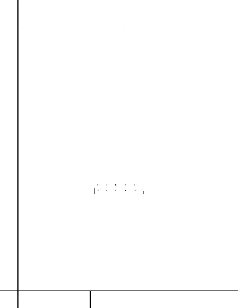
Rear Panel Connections |
HK3370 ONLY |
|
|
|
||||||||
Á |
AM |
|
|
|
|
|
|
|
|
|
|
|
LOOP |
|
|
|
|
|
|
|
|
|
|
|
|
|
|
|
|
|
|
|
|
|
|
|
|
|
ª FM |
|
|
|
|
|
|
|
S P E A K E R 1 ( 8 O h m s ) |
(120V, 60Hz) |
|
|
|
|
|
|
|
|
|
|
|
|
AC 120V 60HZ |
|||
£ |
75 Ω |
GND |
|
|
|
|
|
RIGHT |
LEFT |
|
|
|
|
|
|
|
|
|
|
|
|
|
|
||
|
|
|
|
|
|
|
|
|
|
|
|
|
|
|
PHONO |
CD |
AUX |
TAPE MON. |
TAPE 2 |
MAIN IN PRE OUT SUB OUT |
|
|
|
|
|
|
IN |
|
|
|
|
|
|
L |
|
|
|
400W |
¢ |
|
|
|
|
|
|
|
|
|
|
||
° |
OUT |
IN |
IN |
IN |
PLAY REC. OUT |
PLAY REC. OUT |
MONO |
R |
S P E A K E R 2 ( 8 O h m s ) |
|
|
|
|
|
¤ ¥ â Û Ý ß |
|
¡ |
|
|
||||||
|
|
¦ » Ú Ü Þ à |
|
|
á |
a |
||||||
Á AM Antenna |
|
|
|
|
¥ Aux Inputs |
|
|
Þ Preamp Out |
|
|||
ª FM Antenna |
|
|
|
|
» Tape Monitor Play/In |
|
ß Subwoofer Out |
|
||||
£ Phono Ground |
|
|
|
|
â Tape Monitor Record/Out |
|
à Speaker 1 Terminals |
|
||||
¢ Remote IR In |
|
|
|
|
Ú Tape 2 Play/In |
|
¡ Speaker 2 Terminals |
|
||||
° Remote IR Out |
|
|
|
|
Û Tape 2 Record/Out |
|
á Accessory Outlets |
|
||||
¤ Phono Inputs |
|
|
|
|
Ü Main In |
|
|
a Power Cable |
|
|||
¦ CD Inputs |
|
|
|
|
Ý Pre-Out/Main-In Jumper Pins |
|
|
|
||||
|
|
|
|
|
|
|
|
|
|
|
8 REAR PANEL CONNECTIONS |
|

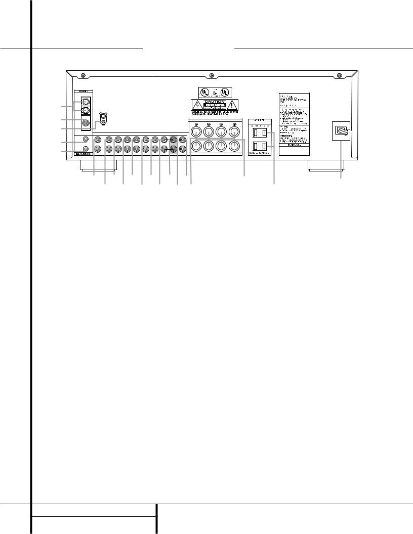
Rear Panel Connections HK3370 ONLY
Á AM Antenna: Connect the AM loop antenna supplied with the receiver to these terminals. If an external AM antenna is used, make connections to the AM and GND terminals in accordance with the instructions supplied with the antenna.
ª FM Antenna: Connect an indoor or external FM antenna to this terminal.
£ Phono Ground: Connect the ground wire from a turntable to this terminal to reduce system hum.
¢ Remote IR In: If the HK 3370’s front panel IR sensor is blocked due to cabinet doors or other obstructions, an external IR sensor may be used. Connect the output of the sensor to this jack.
° Remote IR Out: This connection permits the IR sensor in the receiver to serve other remote controlled devices. Connect this jack to the “IR IN” jack on Harman Kardon or other compatible equipment.
¤ Phono Inputs: Connect the outputs of your turntable or tone arm to these jacks. Note that only Moving Magnet (MM) type cartridges may be used.
¦ CD Inputs: Connect these jacks to the output of a compact disc player or CD changer.
¥ Aux Inputs: Connect these jacks to the line-level output of any audio device such as a TV, cable converter or portable audio player.
»Tape Monitor Play/In: Connect these jacks to the Play/Out jacks of an audio recorder.
âTape Monitor Record/Out: Connect these jacks to the Rec/In jacks of an audio recorder.
NOTE: When these jacks are connected to a three-head recorder or another device with offhead playback, it will be possible to monitor the source being recorded.
ÚTape 2 Play/In: Connect these jacks to the PLAY/OUT jacks of a second audio recorder.
ÛTape 2 Record/Out: Connect these jacks to the Rec/In jacks of a second audio recorder.
Ü Main In: These jacks are the input to the HK 3370’s power amplifier. Unless an external power amplifier is used, the jumper pins should remain connected to the Preamp Out jacks Ý.
Ý Pre-Out/Main-In Jumper Pins:
These pins connect the receiver’s preamp and amplifier sections. Unless an external amplifier, equalizer or speaker processor is used, they should be left connected. See page 12 for more information on external amplifier connections.
Þ Preamp Out: These jacks provide an output for the left and right channels to an optional external amplifier. In normal operation, unless an external power amplifier is used, the jumper pins should remain connected to the Main In jacks Ü.
ß Subwoofer Out: Connect these jacks to the line level input of a powered subwoofer. If an external subwoofer amplifier is used, connect this jack to the subwoofer amplifier input. When a single, mono subwoofer is used, make the connection to the bottom jack.
à Speaker 1 Terminals: Connect these terminals to the appropriate terminals on your speakers.
¡ Speaker 2 Terminals: Connect these terminals to the appropriate terminals on your speakers.
á Accessory Outlets: These outlets may be used to power low-current draw devices such as CD players or cassette decks. The power to these outlets remains on as long as the receiver itself is on. When the receiver is turned off, or placed in the Standby mode, power to these outlets is removed.
NOTE: The power consumption of the devices plugged into these outlets should not exceed 100 watts.
a Power Cable: Connect the AC plug to a nonswitched AC wall output.
9 REAR PANEL CONNECTIONS
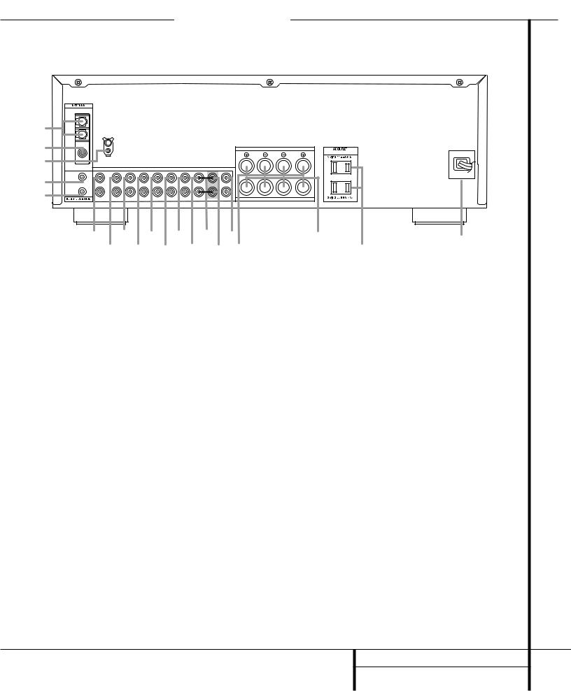
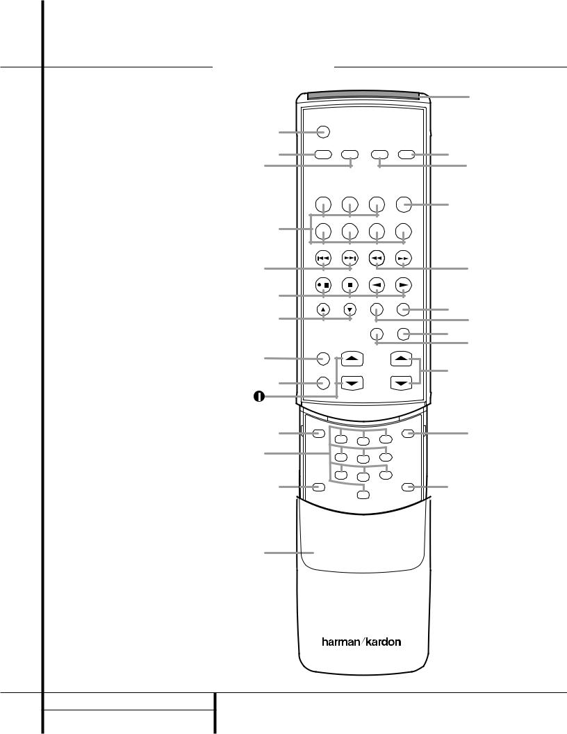
Remote Control Functions HK3370 ONLY
ΠMain Power On
º Main Power Off
• Source Selectors
¶ Preset Up/Down
- Transport Controls
Ä Disc Skip
© Sleep Button
úDimmer Button
”Tuning
Æ Direct Button
û Numeric Keys
 Auto Preset
µ Secondary Control Cover
„ Clear Button
¿ Memory Button
¹ Master Volume
Ï P. Scan Button
¨ Mute Button
§FM Mode Button Tuning Up/Down
† Speaker 1 Selector
à Speaker 2 Selector
· Transmitter Window
|
|
|
|
|
|
· |
Π|
MAIN POWER |
|
SPEAKER |
|
||
ON |
OFF |
|
1 |
2 |
à |
|
º |
|
|
|
|
|
¬¬† |
|
PHONO |
TAPE MON |
TAPE 2 |
|
|
|
|
CD |
AUX |
|
AM |
FM |
|
• |
|
|
|
|
|
|
|
DWN - PRESET - UP DWN - TUNING - UP |
|
||||
¶ |
|
|
|
|
|
|
|
/ |
|
|
|
|
|
- |
DISC SKIP |
|
FM MODE |
|
|
|
Ä |
|
|
|
|
|
§ |
|
|
|
P. SCAN |
MUTE |
|
|
|
|
|
|
|
||
|
SLEEP |
|
|
|
|
¨ Ï |
|
|
|
|
|
|
|
© |
|
|
|
|
|
|
|
DIMMER |
TUNING |
|
MASTER VOL. |
¹ |
|
ú |
|
|
|
|
|
|
Æ |
DIRECT |
|
|
|
MEMORY |
¿ |
|
1 |
2 |
3 |
|
||
|
|
|
|
|||
|
|
|
|
|
|
|
û |
|
4 |
5 |
6 |
|
|
|
|
|
|
|
|
|
|
AUTO |
7 |
8 |
9 |
CLEAR |
|
|
|
|
|
|||
 |
|
0 |
|
„ |
||
|
PRESET |
|
|
|
|
|
µ |
|
|
|
|
|
|
HK 3370 RC
1 0 REMOTE CONTROL FUNCTIONS
Remote Control Functions HK3370 ONLY
ΠMain Power On: When the HK 3370 is in the Standby mode, as indicated by the Power Indicator 3glowing amber, press this button to turn the HK 3370 on.
º Main Power Off: When the HK 3370 is turned on, press this button to place it in the Standby mode. Note that in this condition,
the unit is still connected to AC Power.
•Source Selectors: Press these buttons to select an input source for the HK 3370.
¶ Preset Up/Down: When the tuner is in use, these buttons scroll through the stations that have been programmed into the HK 3370’s memory. These buttons also control the track Skip Up and Down on compatible Harman Kardon compact disc players/changers.
-Transport Controls: These buttons are used to control Play, Play Forward, Play Reverse, Stop, Pause and Record functions on compatible Harman Kardon compact disc players/changers and cassette tape decks.
Ä Disc Skip: These buttons do not have any functions when controlling the HK 3370, but they operate the Disc Skip functions of compatible Harman Kardon compact disc changers.
© Sleep Button: Press this button to place the unit in the Sleep mode. Each press of the button selects the amount of time that will remain before the unit will automatically go into the Standby mode, as shown in the
Information Display ó, in the following order:
|
|
|
90 |
|
80 |
|
|
70 |
|
60 |
|
50 |
|
|||
|
|
|
min |
|
|
min |
|
min |
|
|
min |
|
|
min |
|
|
|
|
|
|
|
|
|
|
|
|
|
|
|
|
|
|
|
|
|
40 |
|
|
30 |
|
|
20 |
|
|
10 |
|
|
OFF |
||
|
|
|
min |
|
|
min |
|
min |
|
|
min |
|
|
|||
|
|
|
|
|
|
|
|
|
|
|
|
|||||
ú Dimmer Button: Press this button once to reduce the brightness of the front panel display to half the normal intensity. Press it again to turn the front panel display completely off.
When the display is completely off, press the button to return to normal brightness.
”Tuning: Press these buttons to tune up or down through a selected frequency band.
Æ Direct Button: Press this button to select a radio station by entering its frequency using the Numeric Keys K. (See page 13 for more information.)
û Numeric Keys: These buttons serve as a ten-button numeric keypad to enter tuner preset positions or to tune stations directly.
 Auto Preset: When the tuner and FM band have been selected, this button may be used to automatically program the tuner presets for all active stations. To start the auto preset scan, press and hold the button. Note that the MEMO and PRESET indicators will flash. After a few seconds, the tuner will start to “look” for active stations, as shown by increasing frequency numbers in the Information Display. Release the button and note that the tuner will briefly stop at each active station and add a preset number to the memory. If the FM tuner finds fewer than 30 FM stations with acceptable signal strength, the Auto Preset tuning will scan two more cycles or until the remaining vacant preset memory spaces have been filled with those found in the first scan. The scan will stop when all 30 preset memory spaces have been filled or when three scans through the band have been completed.
µ Secondary Control Cover: This sliding cover normally is in the “up” position so that it hides the secondary controls. To access these controls, place your thumb on the small recessed area at the top center of the control, and gently press the cover down and towards you.
„ Clear Button: This button is used to clear preset memory information for the HK 3370’s tuner. (See page 14 for more information on tuner presets.)
¿ Memory Button: Press this button to open a memory position that stores a preset location for the HK 3370’s tuner. (See page 14 for more information on tuner presets.)
¹ Master Volume: Press these buttons to raise or lower the HK 3370’s volume.
Ï P. Scan Button: Press this button to automatically scan through the list of stations that are programmed into the HK 3370’s tuner memory. When the button is pressed, each preset station will play for five seconds before the next station is selected. Press the button again when the desired station is heard to stop the preset scan.
¨ Mute Button: Press this button to momentarily silence the HK 3370.
§ FM Mode Button: Press this button when the tuner is in use in the FM band to switch to monaural reception if the station is weak and noisy. (See page 13 for more information.)
Tuning Up/Down: When the tuner is in use, these buttons will tune up or down through the selected frequency band. A brief (1⁄2 second) press of the button will manually tune to the next frequency increment, while pressing and holding the button for a longer period will automatically tune to the next station with a signal strong enough for acceptable reception. These buttons will also control Fast Forward and
Fast Reverse (or Rewind) for compatible Harman Kardon compact disc players/changers and cassette tape decks.
† Speaker 1 Selector: Press this button to turn the speakers connected to the Speaker 1 Output terminals à on or off.
à Speaker 2 Selector: Press this button to turn the speakers connected to the Speaker 2 Output terminals ¡ on or off.
·Transmitter Window: Point this area of the remote toward the receiver when using the remote.
11 REMOTE CONTROL FUNCTIONS

Front Panel Controls HK3470 ONLY
27 |
26 |
25 |
24 |
23 |
MUTE T-MON |
AUTO TUNED ST |
MEMORY PRESET |
|
|
SLEEP |
1 |
|
|
|
2 |
|
|
|
3 |
5 |
7 |
9 ! |
4 |
6 |
8 |
) |
VMAx |
|
|
VMAx |
# % |
|
@ $ |
^ |
& |
( |
21 |
* |
20 |
22 |
1 Main Power Switch |
) Tuning Button |
( Sleep Button |
2 System Power Control |
! Tape Input Selector |
Ó Bass Control |
3 Power Indicator |
@ Preset Scan |
Ô Treble Control |
4 Headphone Jack |
# CD Input Selector |
Balance Control |
5 Mute |
$ Aux Input Selector |
Ò Volume Control |
6 Speaker 1 Selector |
% Preset Selector |
Ú Volume/Mute Indicator |
7 Speaker 2 Selector |
^ VMAx Selector |
Û Main Information Display |
8 Phono Input Selector |
& FM/AM Selector |
Ù Speaker Selection Indicators |
9 T-Mon (Tape Monitor) Input Selector |
* FM Mode Selector |
ı Remote Sensor Window |
1 Main Power Switch: Press this button to apply power to the HK 3470. When the switch is pressed in, the unit is placed in a Standby mode, as indicated by the Power Indicator 3 surrounding the System Power Control 2. This button MUST be pressed in to operate the unit. To turn the unit off and prevent the use of the remote control, this switch should be pressed until it pops out from the front panel so that the word “OFF” may be read at the top of the switch.
NOTE: In normal operation this switch is left in the “ON” position.
2 System Power Control: When the Main Power Switch 1 is “ON,” press this button to turn on the HK 3470; press it again to turn the unit off. Note that the Power Indicator
3surrounding the switch will turn green when the unit is on.
3Power Indicator: This LED will light in amber when the unit is in the Standby mode to signal that the unit is ready to be turned on. When the unit is in operation, the indicator will briefly turn red, and then change to green. A red indicator during normal operation means that the unit is in the Protect mode, and should be turned off and then checked for a possible speaker-wire short circuit.
4 Headphone Jack: This jack may be used to listen to the HK 3470’s output through a pair of headphones. Be certain that the headphones have a standard 1⁄4" stereo phone plug.
5 Mute: Press this button to momentarily silence the speaker output of the HK 3470.
6 Speaker 1 Button: Press this button to turn the speakers connected to the Speaker 1 output terminals ‡ on or off.
7 Speaker 2 Button: Press this button to turn the speakers connected to the Speaker 2 output terminals ° on or off.
12 FRONT PANEL CONTROLS
Front Panel Controls HK3470 ONLY
8 Phono Input Selector: Press this button to select the output of a turntable that is connected to the Phono inputs §.
9T-Mon (Tape Monitor) Input Selector:
Press this button to listen to the output of a tape recorder connected to the Tape Monitor inputs ª. The T-Mon indicator will light to indicate that the input source is being monitored when the HK 3470 is connected to a three-head tape deck or another unit with offhead playback.
)Tuning Button: Press the left side of the button to tune lower-frequency stations and the right side of the button to tune higher-frequency stations. When a station with a strong signal is tuned, the TUNED indicator will light in the
Main Information Display Û. A brief (1/2 second) press of the button will manually tune to the next frequency increment, while pressing and holding the button for a longer period will automatically tune to the next station with a signal strong enough for acceptable reception.
!Tape Input Selector: Press this button to listen to the output of a tape recorder or other device connected to the Tape 2 inputs ⁄.
@ Preset Scan: Press this button to automatically scan through the stations that have been programmed in the HK 3470’s memory.
The tuner will play five seconds of each station before moving to the next preset station. To stop the scan when the desired station is heard, press the button again. (See page 15 for more information on the tuner memory system.)
# CD Input Selector: Press this button to listen to the output of a CD player connected to the CD inputs ¶.
$Aux Input Selector: Press this button to listen to the output of a device connected to the Aux inputs •.
% Preset Selector: Press this button to step up or down through the list of stations that has been entered into the preset memory. (See page 15 for more information on tuner programming.)
^VMAx Selector: Press this button to engage VMAx processing of a stereo input. The
VMAx Mode Indicator A will light, and you will notice a wider, more spacious sound field. In order to obtain maximum benefit, you should
be seated midway between the two loudspeakers, and the same distance from the speakers as the speakers are from each other. The speakers must be placed facing parallel and evenly with each other so that their baffles are in the same plane. Press the button again to return to Stereo mode.
& FM/AM Selector: Press this button to select the tuner as the input to the receiver. When the tuner is in use, press this button to change between the AM and FM frequency bands.
* FM Mode Selector: Press this button to select the Stereo or Mono mode for FM tuning. In the STEREO mode, a Stereo indicator will light in the Main Information Display Û, and stereo reception will be provided when stations are transmitting stereo signals. In the MONO mode, the left and right signals from stereo broadcasts will be mixed together and reproduced through all channels. Select MONO for better reception of weak signals. VMAx will have no effect in MONO mode.
( Sleep Button: Press this button to place the unit in the Sleep mode. Each press of the button selects the amount of time that will remain before the unit automatically goes into the Standby mode, as shown in the Main Information Display Û, in the following order:
|
|
|
90 |
|
80 |
|
|
70 |
|
60 |
|
50 |
|
|||
|
|
|
min |
|
|
min |
|
min |
|
|
min |
|
|
min |
|
|
|
|
|
|
|
|
|
|
|
|
|
|
|
|
|
|
|
|
|
40 |
|
|
30 |
|
|
20 |
|
|
10 |
|
|
OFF |
||
|
|
|
min |
|
|
min |
|
min |
|
|
min |
|
|
|||
|
|
|
|
|
|
|
|
|
|
|
|
|||||
Ó Bass Control: Turn this control to modify the low-frequency output of the left and right channels by as much as ±10dB. Set this control to a suitable position for your taste and room acoustics.
ÔTreble Control: Turn this control to modify the high-frequency output of the left and right channels by as much as ±10dB. Set this control to a suitable position for your taste and room acoustics.
Balance Control: Turn this control to change the relative volume for the left and right channels.
ÒVolume Control: Turn the knob clockwise to increase volume, counterclockwise to decrease the volume.
ÚVolume/Mute Indicator: This indicator will glow green when the HK 3470 is turned on. Its position will enable you to judge the relative volume of the unit even when the speakers are muted or turned off. When the indicator is pointing toward the left, as in an “8 o’clock” position, the volume is low; when it is pointing to the right, as in a “3 o’clock” position, the volume is loud. When the unit has been muted by pressing the Mute button 5, the indicator will flash.
Û Main Information Display: This display delivers messages and status indications to help you operate the receiver.
Ù Speaker Selection Indicators: These indicators light as a green LED next to the designation for each speaker pair to show when they are active. Press the Speaker 1 6 or
Speaker 2 7 Selectors to activate either pair of speakers. Both sets of speakers may be selected simultaneously as long as all speakers have a nominal impedance of 8 ohms or greater. However, occasionally the actual impedance will vary, depending upon the program material. If the impedance drops to a point where there may be potential damage to the equipment, the HK 3470 will go into protect mode.
ı Remote Sensor Window: The sensor behind this window receives infrared signals from the remote control. Aim the remote at this area and do not block or cover it unless an external remote sensor is installed.
13 FRONT PANEL CONTROLS
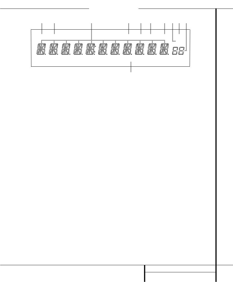
Front Panel Information Display HK3470 ONLY
K |
J |
I |
H |
G F |
E D C B |
MUTE |
T-MON |
|
AUTO |
TUNED ST |
MEMORY PRESET |
|
|
|
|
|
SLEEP |
|
|
|
VMAx |
|
|
|
|
|
A |
|
|
A VMAx Mode Indicator |
|
E Memory Indicator |
|
I Main Information Display |
|
B Preset Number/Sleep Timer |
F Stereo Indicator |
|
J Tape Monitor (T-Mon) Indicator |
||
C Preset Indicator |
|
G Tuned Indicator |
|
K Mute Indicator |
|
D Sleep Indicator |
|
H Auto Indicator |
|
|
|
AVMAx Mode Indicator: This indicator lights when the VMAx mode is in use. (See page 14 for a description of the VMAx Mode.)
B Preset Number/Sleep Timer: When the tuner is in use, these numbers indicate the specific preset memory location in use. (See page 15 for more information on preset stations.) When the Sleep function is in use, these numbers show how many minutes remain before the unit goes into the Standby mode.
C Preset Indicator: This indicator lights when the tuner is in use to show that the
Preset Number/Sleep Timer B is showing the station’s preset memory number. (See page 15 for more information on tuner presets.)
D Sleep Indicator: This indicator lights when the Sleep function is in use. The numbers in the Preset Number/Sleep Timer Indicators will show the minutes remaining before the HK 3470 goes into the Standby mode. (See page 14 for more information on the Sleep function.)
E Memory Indicator: This indicator flashes when entering presets and other information into the tuner’s memory.
F Stereo Indicator: This indicator lights when an FM station is being tuned in stereo.
G Tuned Indicator: This indicator lights when a station is being received with sufficient signal strength to provide acceptable listening quality.
HAuto Indicator: This indicator lights when the tuner’s Auto mode is in use.
I Main Information Display: This display shows messages relating to the status, input source, tuner or other aspects of the HK 3470’s operation.
JTape Monitor (T-Mon) Indicator: When used with three-head cassette decks, or other recording devices that offer immediate playback of the recording as it is being made, the
HK 3470 allows you to monitor a recording rather than merely listening to the input source, or waiting until the recording session is complete in order to hear the recording. Press the
Tape Monitor Input Selector 9ç, and the
T-Mon Indicator J will light to remind you that you are monitoring the recording. Press the
Tape Monitor Input Selector 9ç again to hear the input source.
K Mute Indicator: This indicator lights to remind you that the HK 3470’s output has been silenced by pressing the Mute button 5®. Press the Mute button again to return to the previously selected output level.
14 FRONT PANEL INFORMATION DISPLAY
Rear Panel Connections |
|
HK3470 ONLY |
|
|
|
|
||||||||
|
|
|
|
|
|
|
|
|
|
|
|
|
|
HK3470 |
¡ |
AM |
|
|
|
|
|
|
|
|
|
|
|
|
|
LOOP |
|
|
|
|
|
|
|
|
|
|
|
|
|
|
|
|
|
|
|
|
|
|
|
|
|
|
|
|
|
™ |
FM |
|
|
|
|
|
|
|
|
S P E A K E R 1 ( 8 O h m s ) |
|
(120V, 60Hz) |
|
|
|
|
|
|
|
|
|
|
|
|
|
AC 120V 60HZ |
|||
£ |
75 Ω |
GND |
|
|
|
|
|
|
RIGHT |
LEFT |
|
|
|
|
|
|
|
|
|
|
|
|
|
|
|
|
|
||
|
|
|
|
|
|
|
|
|
|
|
|
|
|
|
|
PHONO |
CD |
AUX |
TAPE MON. |
|
TAPE 2 |
MAIN IN PRE OUT SUB OUT |
|
|
|
|
|
||
|
IN |
|
|
|
|
|
|
|
L |
|
|
|
|
400W |
¢ |
|
|
|
|
|
|
|
|
|
|
|
|
||
|
|
|
|
|
|
|
|
|
|
|
|
|
|
|
∞ |
OUT |
|
|
|
|
|
|
|
R |
|
|
|
|
|
IN |
IN |
IN |
PLAY REC. OUT |
PLAY |
REC. OUT |
|
MONO |
S P E A K E R 2 ( 8 O h m s ) |
|
|
|
|
||
|
§ |
|
• |
|
‚ |
¤ |
› |
fl |
|
° |
|
|
a |
|
|
|
¶ |
|
ª |
⁄ |
‹ |
fi ‡ |
|
|
|
· |
|||
|
|
|
|
|
|
|
||||||||
¡ AM Antenna |
|
|
|
|
|
|
• Aux Inputs |
|
|
|
|
fi Preamp Out |
||
™ FM Antenna |
|
|
|
|
|
|
ª Tape Monitor Play/In |
|
|
|
fl Subwoofer Out |
|||
£ Phono Ground |
|
|
|
|
|
|
‚ Tape Monitor Record/Out |
|
|
|
‡ Speaker 1 Terminals |
|||
¢ Remote IR In |
|
|
|
|
|
|
⁄ Tape 2 Play/In |
|
|
|
|
° Speaker 2 Terminals |
||
∞ Remote IR Out |
|
|
|
|
|
|
¤ Tape 2 Record/Out |
|
|
|
· Accessory Outlets |
|||
§ Phono Inputs |
|
|
|
|
|
|
‹ Main In |
|
|
|
|
a Power Cable |
||
¶ CD Inputs |
|
|
|
|
|
|
|
› Pre-Out/Main-In Jumper Pins |
|
|
|
|
||
15 REAR PANEL CONNECTIONS |
|
|
|
|
|
|
|
|
|
|||||

Rear Panel Connections HK3470 ONLY
¡AM Antenna: Connect the AM loop antenna supplied with the receiver to these terminals. If an external AM antenna is used, make connections to the AM and GND terminals in accordance with the instructions supplied with the antenna.
™ FM Antenna: Connect an indoor or external FM antenna to this terminal.
£ Phono Ground: Connect the ground wire from a turntable to this terminal to reduce system hum.
¢ Remote IR In: If the HK 3470’s front panel IR sensor is blocked due to cabinet doors or other obstructions, an external IR sensor may be used.
Connect the output of the sensor to this jack.
∞ Remote IR Out: This connection permits the IR sensor in the receiver to serve other remote-controlled devices. Connect this jack to the “IR IN” jack on Harman Kardon or other compatible equipment.
§ Phono Inputs: Connect the outputs of your turntable or tonearm to these jacks. Note that only turntables with Moving Magnet (MM) type cartridges may be used.
¶ CD Inputs: Connect these jacks to the output of a compact disc player or CD changer.
•Aux Inputs: Connect these jacks to the line-level output of any audio device such as a TV, cable converter, portable audio player or MP3 player.
ªTape Monitor Play/In: Connect these jacks to the Play/Out jacks of an audio recorder.
‚Tape Monitor Record/Out: Connect these jacks to the Rec/In jacks of an audio recorder.
NOTE: When these jacks are connected to a three-head recorder or another device with offhead playback, it will be possible to monitor the source being recorded.
⁄Tape 2 Play/In: Connect these jacks to the PLAY/OUT jacks of a second audio recorder.
¤Tape 2 Record/Out: Connect these jacks to the Rec/In jacks of a second audio recorder.
‹ Main In: These jacks are the input to the HK 3470’s power amplifier. Unless an external power amplifier is used, the jumper pins should remain connected to the Preamp Out jacks fi.
› Pre-Out/Main-In Jumper Pins: These pins connect the receiver’s preamp and amplifier sections. Unless an external amplifier, equalizer or speaker processor is used, they should be left connected. See page 13 for more information on external amplifier connections.
fi Preamp Out: These jacks provide an output for the left and right channels to an optional external amplifier. In normal operation, unless an external power amplifier is used, the jumper pins should remain connected to the Main In jacks ‹.
fl Subwoofer Out: Connect these jacks to the line-level input of a powered subwoofer. If an external subwoofer amplifier is used, connect this jack to the subwoofer amplifier input. When a single, mono subwoofer is used, make the connection to the bottom jack.
‡ Speaker 1 Terminals: Connect these terminals to the appropriate terminals on your speakers.
° Speaker 2 Terminals: Connect these terminals to the appropriate terminals on your speakers.
·Accessory Outlets: These outlets may be used to power low-current draw devices such as CD players or cassette decks. The power to these outlets remains on as long as the receiver itself is on. When the receiver is turned off, or placed in the Standby mode, power to these outlets is removed.
NOTE: The power consumption of the devices plugged into these outlets should not exceed 100 watts.
a Power Cable: Connect the AC plug to a nonswitched AC wall output.
16 REAR PANEL CONNECTIONS
Remote Control Functions HK3470 ONLY
å Main Power On
∫ Main Power Off
ç Source Selectors
∂ Preset Up/Down
≠ Transport Controls
ƒ Disc Skip
© Sleep Button
˙Dimmer Button
îTuning
∆ Direct Button
˚ Numeric Keys
¬ Auto Preset
µ Secondary Control Cover
Ñ Clear Button
ø Memory Button
π Master Volume
œ P. Scan Button
® Mute Button
ß FM Mode Button
† VMAx Selector
Ü Tuning Up/Down
√ Learn Button
∑ Speaker 1 Selector
≈ Speaker 2 Selector
¥ Transmitter Window
Ω LED Indicator
|
|
|
|
|
|
¥ |
Ω |
|
|
|
|
|
|
å |
MAIN POWER |
|
SPEAKER |
|
||
ON |
OFF |
|
1 |
2 |
≈ |
|
|
|
|
|
|
||
∫ |
|
|
|
|
|
∑ |
|
PHONO |
TAPE MON |
TAPE 2 |
LEARN |
|
|
|
|
|
|
|
|
√ |
|
CD |
AUX |
|
AM |
FM |
|
ç |
|
|
|
|
|
|
|
DWN - PRESET - UP DWN - TUNING - UP |
|
||||
∂ |
|
|
|
|
|
Ü |
|
/ |
|
|
|
|
|
≠ |
DISC SKIP |
|
FM MODE VMAx |
|
||
|
|
|
||||
ƒ |
|
|
|
|
|
† |
|
|
|
P. SCAN |
MUTE |
ß |
|
|
|
|
|
|
||
|
SLEEP |
|
|
|
|
® œ |
|
|
|
|
|
|
|
© |
|
|
|
|
|
|
|
DIMMER |
TUNING |
|
MASTER VOL. |
π |
|
˙ |
|
|
|
|
|
|
∆ |
DIRECT |
|
|
|
MEMORY |
ø |
|
1 |
2 |
3 |
|
||
|
|
|
|
|||
|
|
|
|
|
|
|
˚ |
|
4 |
5 |
6 |
|
|
|
|
|
|
|
|
|
|
AUTO |
7 |
8 |
9 |
CLEAR |
|
|
|
|
|
|||
¬ |
|
|
|
Ñ |
||
PRESET |
|
0 |
|
|
||
|
|
|
|
|
||
µ |
|
|
|
|
|
|
HK 3470 RC
17 REMOTE CONTROL FUNCTIONS
Remote Control Functions HK3470 ONLY
å Main Power On: When the HK 3470 is in the Standby mode, as indicated by the Power Indicator 3glowing amber, press this button to turn the HK 3470 on.
∫ Main Power Off: When the HK 3470 is turned on, press this button to place it in the Standby mode. Note that in this mode, the unit is still connected to AC Power.
ç Source Selectors: Press these buttons to select an input source for the HK 3470.
∂ Preset Up/Down: When the tuner is in use, these buttons scroll through the stations that have been programmed into the HK 3470’s memory. These buttons also control the track Skip Up and Down on compatible Harman Kardon compact disc players and changers.
≠Transport Controls: These buttons are used to control Play, Play Forward, Play Reverse, Stop, Pause and Record functions on compatible Harman Kardon compact disc players/changers and cassette tape decks. Also, when a compatible Harman Kardon compact disc player or changer, or cassette deck, has been selected using the Source Selectors ç, additional transport control functions are available using the Preset Up/Down ∂ and Tuning Up/Down ü buttons.
ƒ Disc Skip: These buttons do not have any functions when controlling the HK 3470, but they operate the Disc Skip functions of compatible Harman Kardon compact disc changers.
© Sleep Button: Press this button to place the unit in the Sleep mode. Each press of the button selects the amount of time that will remain before the unit will automatically go into the Standby mode, as shown in the Main Information Display Û, in the following order:
|
|
|
90 |
|
80 |
|
|
70 |
|
60 |
|
50 |
|
|||
|
|
|
min |
|
|
min |
|
min |
|
|
min |
|
|
min |
|
|
|
|
|
|
|
|
|
|
|
|
|
|
|
|
|
|
|
|
|
40 |
|
|
30 |
|
|
20 |
|
|
10 |
|
|
OFF |
||
|
|
|
min |
|
|
min |
|
min |
|
|
min |
|
|
|||
|
|
|
|
|
|
|
|
|
|
|
|
|||||
˙ Dimmer Button: Press this button once to reduce the brightness of the front panel display to half the normal intensity. Press it again to turn the front panel display completely off. When the display is completely off, press the button to return to normal brightness.
îTuning: Press these buttons to tune up or down through a selected frequency band.
∆ Direct Button: Press this button to select a radio station by entering its frequency using
the Numeric Keys K. (See page 15 for more information.)
˚ Numeric Keys: These buttons serve as a ten-button numeric keypad to enter tuner preset positions or to tune stations directly.
¬Auto Preset: When the tuner and FM band have been selected, this button may be used to automatically program the tuner presets for all active stations. To start the auto preset scan, press and hold the button. Note that the MEMO and PRESET indicators will flash. After a few seconds, the tuner will start to “look”
for active stations, as shown by increasing frequency numbers in the Main Information Display. Release the button and note that the tuner will briefly stop at each active station and add a preset number to the memory. If the FM tuner finds fewer than 30 FM stations with acceptable signal strength, the Auto Preset tuning will scan two more cycles or until the remaining vacant preset memory spaces have been filled with those found in the first scan. The scan will stop when all 30 preset memory spaces have been filled or when three scans through the band have been completed.
µ Secondary Control Cover: This sliding cover normally is in the “up” position so that it hides the secondary controls (the Direct button, Numeric Keys, Auto Preset button, Clear button and Memory button) ∆˚¬Ñø. To access these controls, place your thumb on the small recessed area at the top center of the control, and gently press the cover down and towards you.
Ñ Clear Button: This button is used to clear preset memory information for the HK 3470’s tuner. (See page 15 for more information on tuner presets.)
ø Memory Button: Press this button to open a memory position that stores a preset location for the HK 3470’s tuner. (See page 15 for more information on tuner presets.)
π Master Volume: Press these buttons to raise or lower the HK 3470’s volume.
œ P. Scan Button: Press this button to automatically scan through the list of stations that are programmed into the HK 3470’s tuner memory. When the button is pressed, each preset station will play for five seconds before the next station is selected. Press the button again when the desired station is heard to stop the preset scan.
® Mute Button: Press this button to momentarily silence the HK 3470.
ß FM Mode Button: Press this button when the tuner is in use in the FM band to switch to monaural reception if the station is weak and noisy. (See page 15 for more
information.)
† VMAx Selector: Press this button to engage VMAx processing of a stereo input. The
VMAx Mode Indicator A will light, and you will notice a wider, more spacious sound field. In order to obtain maximum benefit, you should be seated midway between the two loudspeakers, and the same distance from the speakers as the speakers are from each other. The speakers must be placed facing parallel and evenly with each other so that their baffles are in the same plane. Press the button again to return to Stereo mode.
üTuning Up/Down: When the tuner is in use, these buttons will tune up or down through the selected frequency band. A brief (1⁄2 second) press of the button will manually tune to the next frequency increment, while pressing and holding the button for a longer period will automatically tune to the next station with a signal strong enough for acceptable reception. These buttons will also control Fast Forward and
Fast Reverse (or Rewind) for compatible Harman Kardon compact disc players/changers and cassette tape decks.
√ Learn Button: This button is used when you wish to program codes from another device’s remote control into the HK 3470 remote. The simple procedure is described on page 18.
∑ Speaker 1 Selector: Press this button to turn the speakers connected to the Speaker 1 Output terminals ‡ on or off.
≈ Speaker 2 Selector: Press this button to turn the speakers connected to the Speaker 2 Output terminals ° on or off.
¥Transmitter Window: Point this area of the remote toward the receiver when using the remote.
Ω LED Indicator: This indicator will light or blink to confirm various steps in the learning process as the HK 3470 remote is programmed. It will also flicker when a key is pressed during normal operation to indicate that it is transmitting an infrared code.
18 REMOTE CONTROL FUNCTIONS

Troubleshooting Guide
This unit is designed for trouble-free operation. Most problems users encounter are due to operating errors. So, if you have a problem, first check this list for a possible solution. If the problem persists, consult your authorized Harman Kardon Service Center.
If the problem is... |
Make sure that the... |
|
|
No lights illuminate when POWER button is pressed |
Unit is plugged into a live outlet |
|
|
|
Main power switch is pressed in |
|
|
|
|
|
|
No sound is heard |
Unit has not been muted |
|
|
|
Correct input function selector button has been pressed |
|
|
|
Volume is turned up |
|
|
|
The speakers have been turned on using the Speaker Selectors |
|
|
|
|
|
|
No output from one or more channels |
Cables are not defective: check/replace speaker cables |
|
|
|
|
|
|
Tuner sound has a large amount of interference, or |
The antenna is properly connected |
|
|
The “Stereo” display is not illuminated, or |
The antenna is properly located |
|
|
Tuner sound distorts and/or volume level is too low |
The antenna is set in the proper direction |
|
|
|
The antenna is adequate to receive the desired station |
|
|
|
|
|
|
Tuner is intermittent or continuously buzzing or hissing |
The unit is away from fluorescent lights, TVs, motors and |
|
|
|
other electrical appliances |
19 |
|
|
|
|
|
|
|
|
|
1. Test Equipment Required. |
|
AM Standard Signal Generator (AM SSG) |
Audio Generator |
Oscilloscope |
Distortion Meter |
AC Voltmeter |
DC Voltmeter |
FM Standard Signal Generator (FM SSG) |
Frequency Counter |
Stereo Modulator |
|
Note: Disconnect external FM antenna prior to alignment |
|
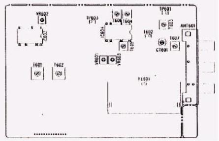
2. Alignment and Test Points |
|
3. AM IF and RF Alingment
Preparation
1.Output of signal Generator should not be higher than necessary to obtain an optimum output reading.
2.Signal Generator Modulation: 30%
3.Switch: Press to AM.
|
|
|
|
|
|
|
|
|
|
||||
|
|
|
|
|||
|
|
|||||
|
|
|
||||
|
|
|
|
|
|
|
|
|
|
|
|
! " # |
|
|
||||||
|
|
|
|
|
||
|
|
|
|
|
|
|
|
|
|
$ |
+ |
! " # |
|
$% &' ( )* |
||||||
|
|
|
|
|
||
|
|
|
|
|
|
|
|
|
|
$ |
|
! " # |
|
$% &' ( )* |
||||||
|
|
|
|
|
||
|
|
|
|
|
|
|
|
|
|
$ |
|
! ,-./ 0 1 '2% 1 |
|
$% &' ( )* |
||||||
|
|
|
|
|
||
|
|
|
|
|
|
|
|
|
|
. . 3 / |
4 |
5 ) ) 6 7 8$ |
|
339 /# 6 : ; < |
||||||
|
|
|
|
|
||
|
|
|
|
|
|
20
4. FM IF Alignment
Preparation
1.Signal Generator output should be no higher than necessary to obtain an optimum output reading.
2.Switch Press to FM
3.Signal Generator Deviation: 75KHz (HK 3370), 40KHz (HK 3470)
|
|
|
|
|
|
|
|
|
|
||||
|
|
|
|
|||
|
|
|||||
|
|
|
||||
|
|
|
|
|
|
|
|
; |
; |
|
|
= ! |
|
|
|
|||||
|
|
|
|
|||
|
|
|
|
|
|
|
|
; |
; |
. |
|
# . |
|
$% &' ( )* |
||||||
|
|
|
|
|
||
|
|
|
|
|
|
|
|
|
|
|
|
,-./ 0 1 '2% 1 5 ) |
|
|
; |
; |
3 . 3 / |
4 |
) 6 7 8 , 339 /# |
|
|
|
|
|
|
6 : >: |
21
5. MPX Alignment, SM Alignment
Preparation
1.Switch: Press to FM
2.Tuner for 98MHz on band.
3.Signal Generator output level: 1000µ V
5. ! " #$ $%& '$ ' %& (Ω
|
|
!"#$ |
|
|
|
|
|
|||
|
|
|
|
|
||||||
|
% |
|
|
|
|
|
||||
|
|
|
|
|
||||||
|
|
|
|
|
|
|||||
|
|
& |
|
|
|
|
|
|
|
|
|
+ |
/ . )8 |
|
$ $% |
|
|
$(#. : > # |
|||
|
4 |
|
&' ( )* : 4 )8 |
|
|
|
: # # /# |
|||
|
|
|
|
|
|
|
||||
|
|
|
|
|
|
|
|
|
|
|
|
|
|
/ . )8 |
|
$ $% |
|
|
$ ! |
||
|
+ |
4 |
|
|
||||||
|
- |
|
&' ( )* : 4 )8 |
|
|
.8 # > . |
||||
|
|
|
|
|
|
|
|
|||
|
|
|
|
|
|
|
|
|
|
? > 7 |
|
+ |
/ . )8 |
|
$ $% |
4 |
|
3 . 3 / |
|||
|
4 |
|
&' ( )* :-)8 |
|
|
|||||
|
|
|
|
|
|
|
|
|||
|
|
|
|
|
|
|
|
|
|
|
5: 0 # ) # |
> @ ? |
! 3 /. |
) / 7 8 3 / (#. 4 # |
0 # > |
||||||
@ ? |
!. : > 8 . /. |
2 . @ ? |
|
|
|
|
|
|||
|
|
|
|
|
|
|
|
|
|
|
22
Pin No. |
Pin Name |
I/O |
ACTIVE |
PORT NAME |
REMARK |
96 |
FIP4 |
O |
H |
G5 |
FIP grid output |
97 |
FIP3 |
O |
H |
G4 |
FIP grid output |
98 |
FIP3 |
O |
H |
G3 |
FIP grid output |
99 |
FIP1 |
O |
H |
G2 |
FIP grid output |
100 |
FIP0 |
O |
H |
G1 |
FIP grid output |
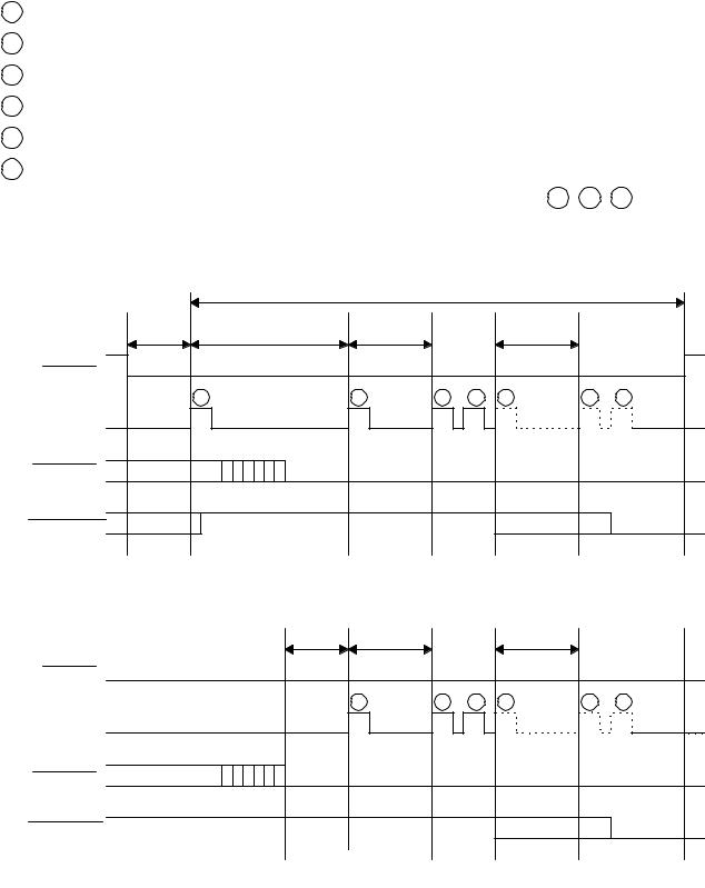
3. Timing Chart (IF Count)
1PLL MODE 1
2PLL MODE 2
3PLL MODE 3
4PLL MODE 2
5PLL MODE 3
6PLL MODE 1
...... |
4 5 6 |
A dotted line ( ) : In case that IF COUNT is not proper, follow PLL MODE of |
When changing BAND, selecting the PRESET STATION using TEN KEY and selecting the PRESET STATION using PRESET CHANNEL UP/DOWN
|
|
|
|
|
|
|
|
1 2 3 1 4 5 6
When IF COUNT is not proper in case that the frequency is not tuned |
|
|
|
||
|
|
|
|
|
|
|
|
|
|
|
|
2 |
3 |
1 |
4 |
5 |
6 |
23

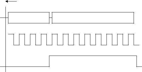
MANUAL TUNING UP/DOWN
|
|
|
|
|
|
|
|
|
|
|
|
|
|
|
|
|
|
|
|
|
|
1 |
1 |
1 |
1 |
1 |
1 |
MANUAL TUNING UP/DOWN KEY OFF
|
|
|
|
|
|
|
|
|
|
|
|
|
|
|
|
|
|
|
|
|
|
|
|
1 2 3 1 4 5 6


24

- POWER ON
|
|
|
|
|
|
|
|
|
|
|
|
|
|
|
|
|
|
|
|
1 2 3 1 4 5 6


- AUTO TUNING UP/DOWN
|
|
|
|
|
|
|
|
|
|
|
|
|
|
1 |
1 |
2 |
3 |
1 |
2 |
3 |
1 |
2 |
3 |
1 |
4 |
5 |
6 |
25
4. Pheriperal IC Operation
1) FUNCTION IC. : LC7821-1/3

26

2) PLL IC. (LC7218) |
|
|
|
|
|
|
|
|
|
|
|
|
|
|
|
|
|
|
|
|
|
|
|
|
|
|
|
|
|
|
|
|
|
|
|
|
|||||||||||
|
|
|
|
|
1) MODE 1 : FREQUENCY OUT/ TUNED CHECK |
|
|
|
|
|
|
|
|
|
|
|
|
|
|
|
|||||||||||||||||||||||||||
|
|
|
|
|
|
|
|
|
|
|
|
|
|
|
|
|
|
|
|
|
|
|
|||||||||||||||||||||||||
|
|
|
|
|
|
|
|
|
|||||||||||||||||||||||||||||||||||||||
|
|
|
|
|
|||||||||||||||||||||||||||||||||||||||||||
|
|
|
|
|
|
|
|
|
|
|
|
|
|
|
|
|
|
|
|
|
|
|
|
|
|
|
|
|
|
|
|
|
|
|
|
|
|
|
|
|
|
|
|
|
|
|
|
|
|
|
|
|
|
|
|
|
|
|
|
|
|
|
|
|
|
|
|
|
|
|
|
|
|
|
|
|
|
|
|
|
|
|
|
|
|
|
|
|
|
|
|
|
|
|
|
|
|
|
|
|
|
|
|
|
|
|
|
|
|
|
|
|
|
|
|
|
|
|
|
|
|
|
|
|
|
|
|
|
|
|
|
|
|
|
|
|
|
|
|
|
|
|
|
|
|
|
|
|
|
|
|
|
|
|
|
|
|
|
|
|
|
|
|
|
|
|
|
||||||||||||||||||||||||
|
|
|
|
|
|
|
|
|
|
|
|
|
|
||||||||||||||||||||||||||||||||||
|
|
|
|
|
|
|
|
|
|
|
|
|
|
|
|
|
|
|
|
|
|
|
|
|
|
|
|
|
|
|
|
|
|
|
|
|
|
|
|
|
|
|
|
|
|
|
|
|
|
|
|
|
|
|
|
|
|
|
|
|
|
|
|
|
|
|
|
|
|
|
|
|
|
|
|
|
|
|
|
|
|
|
|
|
|
|
|
|
|
|
|
|
|
|
|
|
|
|
|
|
2) MODE 2 : FREQUENCY OUT/ OUTPUT CONTROL |
|
|
|
|
|
|
|
|
|
|
|
|
|
|
|
|||||||||||||||||||||||||||
|
|
|
|
|
|
|
|
|
|
|
|
|
|
|
|
|
|
|
|
|
|||||||||||||||||||||||||||
|
|
|
|
|
|
|
|
|
|
|
|
|
|
|
|
|
|
|
|
|
|
|
|
|
|
|
|
|
|
|
|
|
|
|
|
|
|
|
|
|
|
|
|
|
|||
|
|
|
|
|
|
|
|
|
|
||||||||||||||||||||||||||||||||||||||
|
|
|
|||||||||||||||||||||||||||||||||||||||||||||
|
|
|
|
|
|
|
|
|
|
|
|
|
|
|
|
|
|
|
|
|
|
|
|
|
|
|
|
|
|
|
|
|
|
|
|
|
|
|
|
|
|
|
|
|
|
|
|
|
|
|
|
|
|
|
|
|
|
|
|
|
|
|
|
|
|
|
|
|
|
|
|
|
|
|
|
|
|
|
|
|
|
|
|
|
|
|
|
|
|
|
|
|
|
|
|
|
|
|
|
|
|
|
|
|
|
|
|
|
|
|
|
|
|
|
|
|
|
|
|
|
|
|
|
|
|
|
|
|
|
|
|
|
|
|
|
|
|
|
|
|
|
|
|
|
|
|
|
|
|
|
|
|
|
|
|
|
|
|
|
|
|
|
|
|
|
|
|
||||||||||||||||||||||||
|
|
|
|
|
|
|
|
|
|
|
|
|
|
||||||||||||||||||||||||||||||||||
|
|
|
|
|
|
|
|
|
|
|
|
|
|
|
|
|
|
|
|
|
|
|
|
|
|
|
|
|
|
|
|
|
|
|
|
|
|
|
|
|
|
|
|
|
|
|
|
|
|
|
|
|
|
|
|
|
|
|
|
|
|
|
|
|
|
|
|
|
|
|
|
|
|
|
|
|
|
|
|
|
|
|
|
|
|
|
|
|
|
|
|
|
|
|
|
|
|
|
3) MODE 3 : IF COUNT READ |
|
|
|
|
|
|
|
|
|
|
|
|
|
|
|
|
|
|
|
|
|
|
|
|
|
|
|
|||||||||||||||||
|
|
|
|
|
|
|
|
|
|
|
|
|
|
|
|
|
|
|
|
|
|
|
|
|
|
|
|
|
|
|
|||||||||||||||||
|
|
|
|
|
|
|
|
|
|
|
|
|
|
|
|
|
|
|
|
|
|
|
|
|
|
|
|
|
|
|
|
|
|
|
|
|
|
|
|
|
|
|
|
|
|
||
|
|
|
|
|
|
|
|
||||||||||||||||||||||||||||||||||||||||
|
|
|
|||||||||||||||||||||||||||||||||||||||||||||
|
|
|
|
|
|
|
|
|
|
|
|
|
|
|
|
|
|
|
|
|
|
|
|
|
|
|
|
|
|
|
|
|
|
|
|
|
|
|
|
|
|
|
|
|
|
|
|
|
|
|
|
|
|
|
|
|
|
|
|
|
|
|
|
|
|
|
|
|
|
|
|
|
|
|
|
|
|
|
|
|
|
|
|
|
|
|
|
|
|
|
|
|
|
|
|
|
|
|
|
|
|
|
|
|
|
|
|
|
|
|
|
|
|
|
|
|
|
|
|
|
|
|
|
|
|
|
|
|
|
|
|
|
|
|
|
|
|
|
|
|
|
|
|
|
|
|
|
|
|
|
|
|
|
|
|
|
|
|
|
|
|
|
|
|
|
|
|
|
|
||||||||||||||||||||||
|
|
|
|
|
|
|
|
|
|
|
|
|
|
|
|
|
|||||||||||||||||||||||||||||||
27

HK3370 / HK3470
4. BLOCK DIAGRAM
28

19
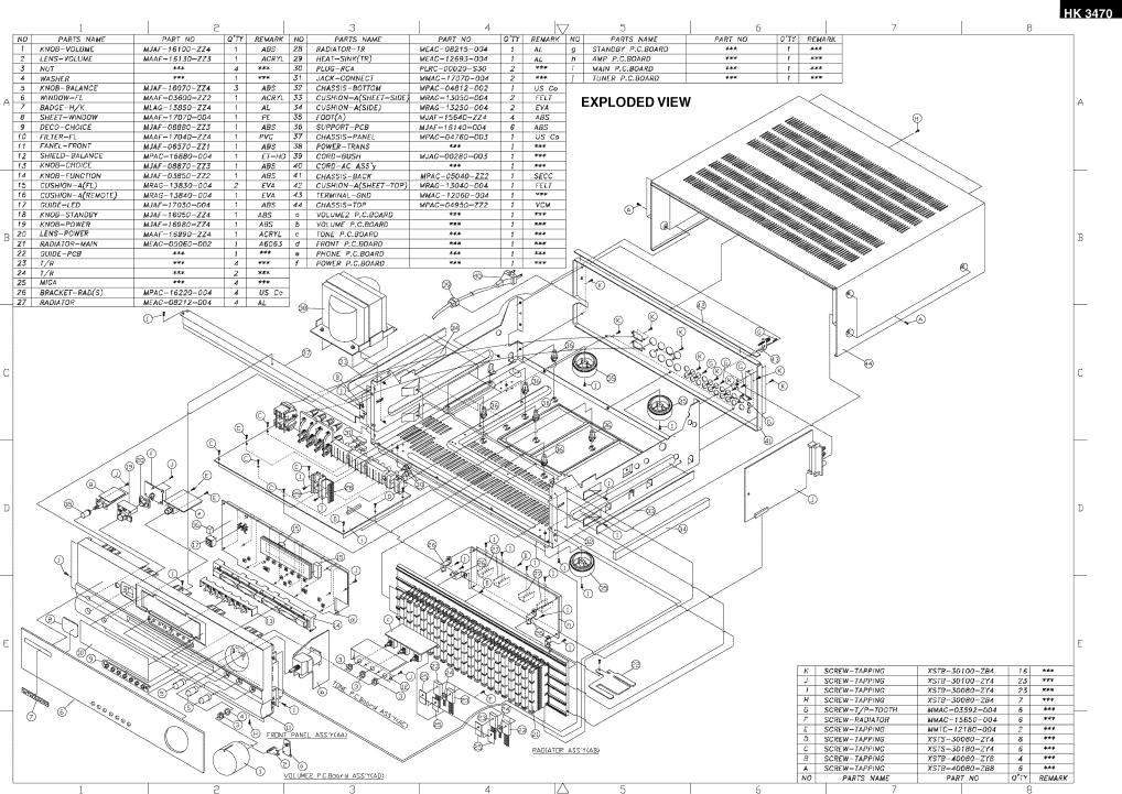
20
 Loading...