


GSK980TD Turning CNC
PLC User Manual

Book 1 PROGRAMMING
PLC specification, PLC address, ladder
Programming 1 Book
Book 2 FUNCTION
PLC function control logic and relative signals
Book 3 CNC CONFIGRUTION SOFTWARE
GSKCC software and usage
software Configuration CNC 3 Book Function 2 Book

APPENDIX
Appendix 1 input signal X ……………………………………………appendix-1
Appendix 2 output signal Y ………………………………………….appendix-2
Appendix 3 G, F signal……………………….…………………………. appendix-3 Appendix 4 GSK980TD standard function configuration……………. appendix-8
Appendix

BOOK 1
PROGRAMMING
Programming 1 Book

Contents
Chapter 1 SEQUENTIAL PROGRAM ........................................................................................ |
-1 |
1.1 PLC SPECIFICATION .................................................................................................... |
-1 |
1.2 STRUCTURE of SEQUENTIAL PROGRAM ............................................................... |
-1 |
1.2.1 Subprogram............................................................................................................ |
-1 |
1.2.2 Subprogram Embedding ........................................................................................ |
-2 |
1.2.3 Conditional Branch ................................................................................................ |
-3 |
1.3 EXECUTING SEQUENTIAL PROGRAM .................................................................... |
-3 |
1.3.1 Execution Process of Sequential Program ............................................................. |
-3 |
1.3.2 Cycle Execution of Sequential Program ................................................................ |
-4 |
1.3.3 Priority Order of Executing Sequential Program................................................... |
-4 |
1.4 PROCESSING INPUT/OUTPUT SIGNAL.................................................................... |
-5 |
1.4.1 Processing Input Signal.......................................................................................... |
-5 |
1.4.2 Processing Input Signal.......................................................................................... |
-6 |
1.4.3 Synchronous Procession of Short Pulse Signal ..................................................... |
-7 |
1.4.4 Interlock Signal...................................................................................................... |
-7 |
1.5 EDITING SEQUENTIAL PROGRAM........................................................................... |
-7 |
1.5.1 Distributing Interface (Step 1) ............................................................................... |
-8 |
1.5.2 Editing Ladder (Step 2).......................................................................................... |
-8 |
1.5.3 Debugging Ladder (Step 3).................................................................................... |
-8 |
1.5.4 Program Editing Limit ........................................................................................... |
-8 |
Chapter 2 ADDRESS.................................................................................................................... |
-1 |
2.1 MACHINE→PLC ADDRESS X .............................................................................. |
-1 |
2.1.1 X Address in I/O Interface ..................................................................................... |
-2 |
2.1.2 X Address on Operator Panel................................................................................. |
-2 |
2.2 PLC→MACHINE ADDRESS Y .............................................................................. |
-3 |
2.2.1 Y Address in I/O Interface ..................................................................................... |
-3 |
2.2.2 Y Addresses on Operator Panel.............................................................................. |
-4 |
2.3 PLC→NC ADDRESS G ........................................................................................... |
-4 |
2.4 NC→PLC ADDRESS F ........................................................................................... |
-4 |
2.5 INTERNAL RELAY ADDRESS..................................................................................... |
-4 |
2.6 INFORMATION DISPLAYING REQUEST ADDRESS A ..................................... |
-5 |
2.7 HOLD RELAY ADDRESS K ................................................................................... |
-5 |
2.8 COUNTER ADDRESS C ......................................................................................... |
-6 |
2.9 COUNTER PRESET VALUE ADDRESS DC ......................................................... |
-6 |
2.10 TIMER ADDRESS T .............................................................................................. |
-6 |
2.11 TIMER PRESET VALUE ADDRESS DT .............................................................. |
-7 |
2.12 DATA LIST ADDRESS D ...................................................................................... |
-7 |
2.13 LABEL ADDRESS L ............................................................................................. |
-8 |
2.14 SUBPROGRAM NUMBER P ................................................................................ |
-8 |
Chapter 3 PLC BASIC INSTRUCTIONS.................................................................................... |
-1 |
3.1 LD LDI OUT INSTRUCTION.................................................................................. |
-1 |
3.2 AND, ANI INSTRUCTION............................................................................................. |
-2 |
3.3 OR, ORI INSTRUCTION ............................................................................................... |
-2 |
3.4 ORB INSTRUCTION...................................................................................................... |
-3 |
3.5 ANB INSTRUCTION...................................................................................................... |
-3 |
Chapter 4 PLC FUNCTION INSTRUCTIONS ........................................................................... |
-1 |
Programming 1 Book
I

Programming 1 Book
|
|
GSK980TD Turning Machine CNC System |
|
|
|
|
|
|
|
|
|
|
4.1 END1 END of GRADE ONE PROGRAM .............................................................. |
-1 |
|
|
4.2 END2 END of GRADE TWO PROGRAM ............................................................. |
-1 |
|
|
4.3 SET .................................................................................................................................. |
-2 |
|
|
4.4 RST(RESET) ................................................................................................................... |
-2 |
|
|
4.5 CMP BINARY COMPARATIVE SET ..................................................................... |
-3 |
|
|
4.6 TMRB TIMER .......................................................................................................... |
-4 |
|
|
4.7 CTRC BINARY COUNTER .................................................................................... |
-5 |
|
|
4.8 MOVN BINARY DATA COPY ............................................................................... |
-6 |
|
|
4.9 DECB BINARY ENCODING .................................................................................. |
-7 |
|
|
4.10 CODB BINARY CODE CONVERSION ............................................................... |
-7 |
|
|
4.11 JMPB PROGRAM JUMPING ............................................................................... |
-9 |
|
|
4.12 LBL PROGRAM JUMPING LABEL .................................................................... |
-9 |
|
|
4.13 CALL SUBPROGRAM CALLING ..................................................................... |
-10 |
|
|
4.14 SP START of SUBPROGRAM , SPE END of SUBPROGRAM .................. |
-10 |
|
|
4.15 ROTB BINARY ROTATION CONTROL ........................................................... |
-11 |
|
|
4.16 PARI PARITY CHECK ........................................................................................ |
-13 |
|
|
4.17 ADDB BINARY DATA ADDING ........................................................................ |
-14 |
|
|
4.18 SUBB BINARY DATA SUBTRACTING ............................................................ |
-15 |
|
|
4.19 DIFU DRIFT UP SET .......................................................................................... |
-16 |
|
|
4.20 DIFD DRIFT DOWN SET ................................................................................... |
-16 |
|
|
4.21 MOVE AND ......................................................................................................... |
-17 |
|
|
4.22 ALT ALTERNATIVE OUTPUT .......................................................................... |
-18 |
|
II

Chapter 1 Sequential Program
Chapter 1 SEQUENTIAL PROGRAM
1.1 PLC SPECIFICATION
For different CNC PLC, there are different program capacity, processing speed, function instructions and nonvolatile memory addresses. Specifications of GSK980TD PLC are as follows:
Specification |
980TD-PLC |
||
Programming language |
Chinese ladder |
||
Programming software |
GSKCC.exe |
||
Programming grades |
2 |
||
Executive cycle of grade one program |
8ms |
||
Average processing time of basic instruction |
<2μs |
||
Max. step of program |
5000 steps |
||
Programming instruction |
Basic instruction +function instruction |
||
|
Internal relay address R |
R0000 R0999 |
|
|
Information displaying request address A |
A0000 A0024 |
|
|
Timer address T |
T0000 T0099 |
|
Programming |
Counter address C |
C0000 C0099 |
|
Data tablet address D |
D0000 D0999 |
||
Hold relay address K |
K0000 K0039 |
||
Counter preset value address DC |
DC0000 DC0099 |
||
Timer preset value address DT |
DT0000 DT0099 |
||
address |
|
|
|
Subprogram address P |
P0000 P9999 |
||
Label address L |
L0000 L9999 |
||
Machine→PLC address X |
X0000 X0029 |
||
|
|||
|
PLC→machine address Y |
Y0000 Y0019 |
|
|
CNC→PLC address F |
F0000 F0255 |
|
|
PLC→CNC address G |
G0000 G0255 |
|
1.2 STRUCTURE of SEQUENTIAL PROGRAM
Sequential program is defined to logically control the machine and relative devices according to sequence of ladder. The sequence of ladder is compiled in a traditional PLC but GSK980TD CNC PLC is integrated by traditional one and advanced structured programming, employed with subprogram, embedded subprogram and conditional branch and with apparent advantages compared to the traditional.
Programming 1 Book
1.2.1 Subprogram
In GSK980TD CNC PLC program, a special subprogram can be called according to requirements of programming. For example, subprogram P0001 can be called when contactor X0000.0 is closed as follows:
-1

GSK980TD Turning Machine CNC System
Programming 1 Book
1.2.2 Subprogram Embedding
Call subprogram P0001
Subprogram P0001
GSK980TD CNC PLC can realize 20 grades subprogram embedding as the following figure. Subprogram P0001 can be called when contractor X0000.0 is closed in main program; subprogram P0002 can be called when contractor X0002.0 is closed in the subprogram P0001.
Subprogram P0001
Subprogram P0001
Call subprogram P0002
-2
Chapter 1 Sequential Program
Subprogram P0002
1.2.3 Conditional Branch
The system can judge whether the setting conditions to execute a corresponding subprogram are satisfactory when a main program is executed circularly, otherwise the system executes subprograms in order as the above-mentioned figure.
Programming 1 Book
1.3 EXECUTING SEQUENTIAL PROGRAM
The edited sequential programs(ladder program)are downloaded to 980TD by serial, CNC reads the ladder and converts into some format identified by it after it is switched on again, and then CPU decodes and operation processes them to store into RAM, and last reads every instruction in memory to execute it by arithmetical operation.
1.3.1 Execution Process of Sequential Program
PLC sequence control is executed by software and there is different from general relay circuit, and so its method is understandingly considered in editing PLC sequential programs.
Every relay can output simultaneously for general relay control circuit as the following figure. Y0002.3 and Y0002.5 output simultaneously when contactor X0000.0, X0002.0 and X0002.2 are closed; in PLC sequence control, every relay outputs in order. For example, Y0002.3 outputs and then Y0002.5 does when X0000.0, X0002.0 and X0002.2 are closed, namely, outputs are executed in order as ladder.
-3

GSK980TD Turning Machine CNC System
Programming 1 Book
1.3.2 Cycle Execution of Sequential Program
Cycle execution of sequential program is defined that PLC executes ladder from its home to end, and again from its home to end after the run is completed.
Processing cycle is defined to runtime of ladder from home to end. The shorter the processing cycle is, the stronger the response of signal is.
1.3.3 Priority Order of Executing Sequential Program
GSK980TD PLC programs are divided into grade one and grade two programs which processing cycles are different. The first one is executed per 8ms to do with short pulse signal with quick reaction, and the second one is executed per 8n(ms),in which n is fraction times. PLC divides the grade two program into n blocks according to runtime, and executes one block per each 8(ms).
End of grade one program
Fraction 1: 0004 0006
Fraction 1: 0007 0011
End of grade one program
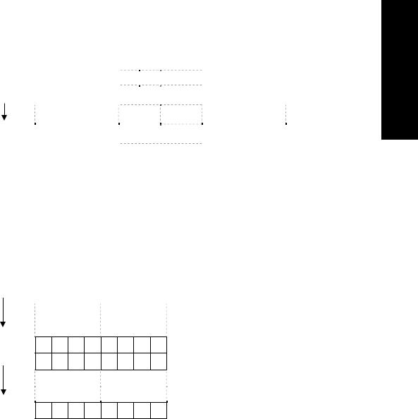
Fraction of the grade two program is to execute the first and execution process is as the following figure when the fraction number is n; T11, T12, T1n are runtime to execute the first. T21, T22, T2n separately corresponds to runtime of No. n block in executing the second when No. n cycle is execute. Tc1, Tc2, Tcn separately corresponds to hold time by CNC when No. n cycle is executed.
The program returns to its beginning to continue execution when the last fraction block of the second is executed completely. The first is executed every 8ms, No. n block of the second is done every 8n, and runtime
-4
Chapter 1 Sequential Program
of one cycle is 8n(ms). The more the fraction number of the second is, the longer the runtime of one cycle is.
|
|
|
|
|
8ms |
|
|
|
|
|
8ms |
|
|
|
|
|
8ms |
|
|
|
|
|
|
|
||||||||||
|
|
|
|
|
|
|
|
|
|
|
|
|
|
|
|
|
||||||||||||||||||
|
|
|
1ms |
|
|
|
|
|
1ms |
|
|
|
|
|
|
1ms |
|
|
|
|
|
|
|
|
|
|||||||||
|
|
|
|
|
|
|
|
|
|
|
|
|
|
|
|
|
|
|
|
|||||||||||||||
|
|
|
|
|
|
|
|
|
|
|
|
|
|
|
|
|
|
|
|
|
|
|
|
|
|
|
|
|
|
|
|
|
|
|
T11 |
|
Block 1 |
|
T12 |
Block 2 |
|
T1n |
Block n |
|
|
|
|
|
Block 1 |
||||||||||||||||||||
|
|
|
|
|
|
|
|
|
|
|
|
|
|
|
|
|
|
|
|
|
|
|
|
|
|
|
|
|
|
|
|
|
|
|
|
|
|
|
|
|
|
|
|
|
|
|
|
|
|
|
|
|
|
|
|
|
|
|
|
|
|
|
|
|
|
|
|
||
|
|
|
|
T21 |
|
|
|
|
|
|
|
|
T22 |
|
|
|
|
|
|
|
|
|
T2n |
|
|
|
|
|
|
|
|
|
|
|
|
|
|
|
|
|
|
|
|
|
|
|
|
|
|
|
|
|
|
|
|
|
|
|
|
|
|
|
|
|
|
|
|
|
|
|
|
|
|
|
|
|
|
|
|
|
|
|
|
|
|
|
|
|
|
|
|
|
|
|
|
|
|
|
|
|
|
|
|
|
|
|
|
|
|
|
|
|
|
|
|
|
|
|
|
|
|
|
|
|
|
|
|
|
|
|
|
|
|
|
|
|
|
|
|
|
|
|
|
|
|
|
|
Tc1 |
|
|
|
|
|
|
|
|
Tc2 |
|
|
|
|
|
|
|
|
|
|
Tcn |
||||||
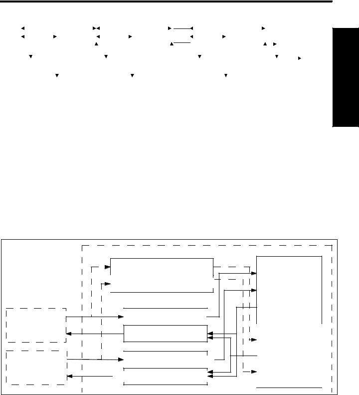
1.4 PROCESSING INPUT/OUTPUT SIGNAL
Processing of input/output signal is as the following figure. X signal of machine I/O interface and F signal of NC are separately input to input memories at machine side and NC side, and directly used by the first grade program; they separately input to synchronous input memories are used by the second. Output signals of the first and the second are separately output to output memories at NC side and machine side and then separately output to NC and I/O interface of machine
Signal states of the above-mentioned memories are displayed by diagnostic interface, and the diagnostic number corresponds to address number of program.
Programming 1 Book
|
|
PLC |
|
|
|
SynNC. input memory at CN side |
|
|
|
Syn. input memory at machine side |
Grade one program |
|
|
|
|
|
|
|
|
|
|
F |
|
|
|
NC |
|
N |
C |
Input memory at CN side |
|
G |
|
||
|
|
NC |
|
|
|
Output memory at CN side |
|
|
|
X |
Grade two program |
|
|
|
|
Machine |
|
Input memory at machine side |
|
|
Y |
|
|
|
|
Output memory at machine side |
|
1.4.1 Processing Input Signal
A Input signal of grade one program:
Input memory at NC side is scanned every 8ms and stores F signal from NC, and the system directly use its state when the first is executed.
B Input signal of grade two program:
Input signal of the second is the one stored by the first. The first directly use F and X signal and so the input
-5
GSK980TD Turning Machine CNC System
Programming 1 Book
signal of the second lags the first one and its max. lag time is runtime of one grade two program.
C Difference of input signal states of the first and the second:
For the same input signal, its states are different in the first and the second when PLC reads input signals, because the first reads input memories at NC side and machine side but the second reads the synchronous input memory at NC side and ones at machine side. The input signal of the second lags behind that of the first and its lag time is 8nms which should be noted.
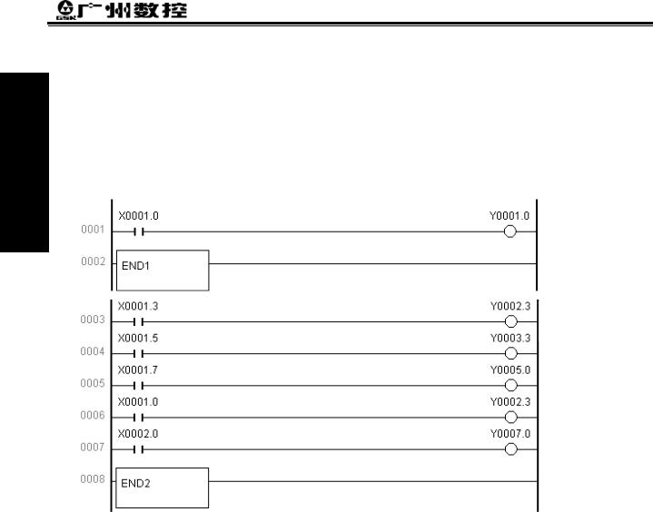
Example
End of grade one program
Fraction1: 0003 0005
Fraction1: 0006 0007
End of grade two program
When the lag time is the first 8ms, X0001.0=1 and the system executes the first Y0001.0=1. When the system starts to execute the second, X0001.0 1 inputs to the synchronous input memory and starts to execute the first block of the fractional second.
When the lag time is the second 8ms, X0001.0=0 and the system executes the first one Y0001.0=1. And then the system executes the second block of the fractional second but X0001.0 =1 which state is still the previous synchronous input memory and Y0002.3=1 after execution.
1.4.2 Processing Input Signal
A Signal to NC
PLC transmits output signal to the output memory at NC side every 8ms, and then directly outputs to NC. B Signal to machine
PLC transmits output signal to the output memory at machine side, and then directly outputs to memory every 2ms.
-6
Chapter 1 Sequential Program
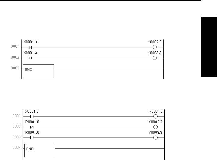
1.4.3 Synchronous Procession of Short Pulse Signal
The first is used for processing the short pulse signal. When it is less than 8ms, namely when the system executes the first, the input signal state may be changed, which may execute programs by mistake.
End of grade one program
As above, X0001.3=0 is changed to X0001.3=1 after Y0002.3=1 is executed, and if the system executes the next line of ladder and Y0003.3=1, at the moment Y0002.3=1 and Y0003.3=1. To avoid the above, process synchronously the short pulse signal as follows:
End of the first grade program
After the program is executed synchronously and when X0001.3=1 Y0003.3=1 Y0002.3=0 X0001.3=0 Y0002.3=1 and Y0003.3=0 but Y0003.3=1 or Y0002.3=1.
1.4.4 Interlock Signal
For safety, the signals must be employed with soft interlock in sequence control, and with hard interlock to relay control circuit of power electric box at machine side at the same time. Because the hardware is failure, the interlock is invalid in executing sequential program even if it is employed logically with soft interlock, which can ensure the operator is not injured and the machine is prevented from damage.
Programming 1 Book
1.5 EDITING SEQUENTIAL PROGRAM
Edit the sequential program from ladder which is composed of relay contacts, symbols and function instructions. Logic relationship in ladder consists of sequential program which is edited by two methods: one is employed with input to use program instructions and the other is with relay symbols by their corresponding contactor, symbol and function instruction. Edit the sequential program employed with the ladder format instead of mnemonic code language when the system is employed with the relay symbol.
In actual editing sequential program, use programming instruction or ladder to edit it according to PLC. In the User Manual, the system is employed with ladder as follows:
-7

GSK980TD Turning Machine CNC System
ogrammingPr 1 Book
1.5.1 Distributing Interface (Step 1)
The interfaces can be distributed after control target is defined and the corresponding input/output signal points are counted. Refer to input/output interface signal list
1.5.2 Editing Ladder (Step 2)
Edit the software GSKCC.EXE by 980TD ladder to represent the required control operations of machine. Counter, timer which are not done by relay symbol is represented by the specified function instructions. The edited ladder is downloaded to CNC by serial.
1.5.3 Debugging Ladder (Step 3)
After the ladder is downloaded to 980TD, the ladder is debugged as follows:
A emulator
Use one emulator instead of machine to debug it. Machine signal state is represented with switch ON/OFF, and output signal state is done with indicator ON/OFF. Observe if every indicator on the emulator is correct when executing CNC.
B CNC diagnosis
Observe if the diagnostic state of every signal is consistent with the function requirement when executing CNC. Check the ladder by checking each function in order.
C actual run
There may be an unexpected result in the actual debugging machine and so do preventive measures before debugging.
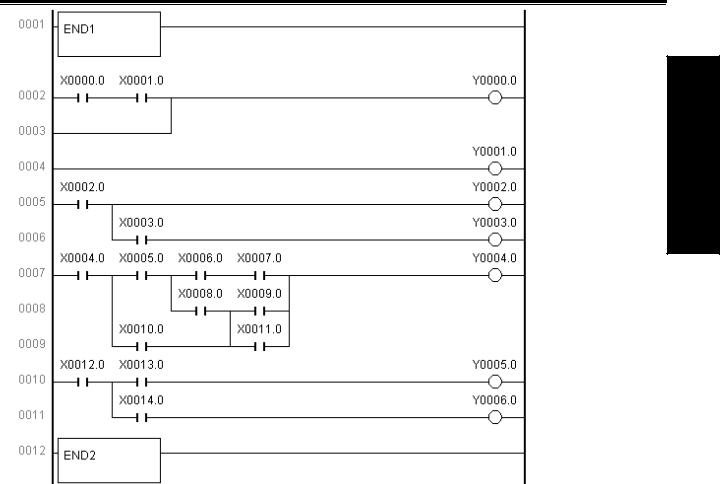
1.5.4 Program Editing Limit
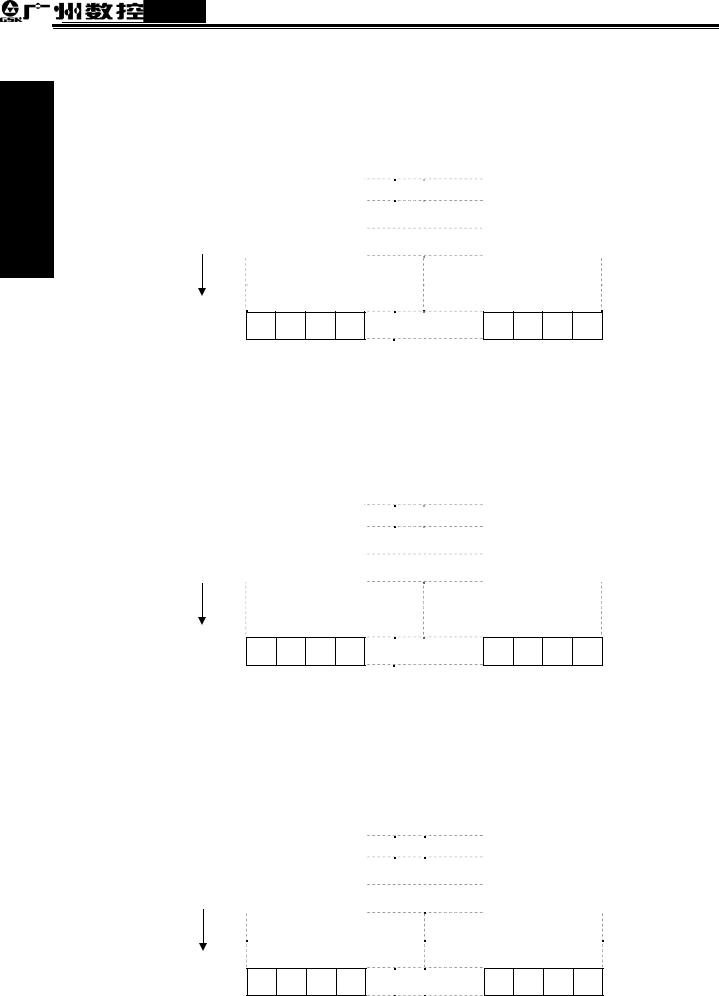
In program, END1 and END2 are needed, which are taken separately as ending character of the first and the second, and END1 must be before END2. The system only supports parallel output instead of multi grades output and there are syntactic errors as follows:
-8
Chapter 1 Sequential Program
End of grade one program
Syntactic error: 0002 0003
Syntactic error: 0004
Syntactic error: 0005 0006
Syntactic error: 0007 0009
Syntactic error: 0010 0011
Programming 1 Book
-9
Chapter 2 |
Address |
|
|
Chapter 2 ADDRESS
Addresses are used for distinguishing signals. Different addresses separately correspond to input/output signal at machine side and CNC side, internal relay, counter, timer, holding relay and data list. An address number is consisted of address type, address number and bit number as follows:
X 0001.6
Bit number
 Address number
 Address type
Address type: X, Y, R, F, G, K, A, T, DT, DC, C, D, L, P Address number: decimal number to express one byte
Bit number: octal number, 0 7 separately expressing byte 0 7 bit of front address number
980TD PLC addresses are divided into fixed addresses and definable addresses. Signal definitions of the fixed addresses cannot be changed and are defined by CNC; the definable addresses can be defined again by user according to the actual requirements. Address types are as follows:
Programming 1 Book
Address |
Explanation |
Range |
X |
Machine→PLC |
X0000 X0029 |
Y |
PLC→machine |
Y0000 Y0019 |
F |
NC→PLC |
F0000 F0255 |
G |
PLC→NC |
G0000 G0255 |
R |
Intermediate relay |
R0000 R0999 |
D |
Data register |
D0000 D0999 |
C |
Counter |
C0000 C0099 |
T |
Timer |
T0000 T0099 |
DC |
Counter preset value register |
DC0000 DC0099 |
DT |
Timer preset value register |
DT0000 DT0099 |
A |
Information displaying request signal |
A0000 A0024 |
K |
Hold relay |
K0000 K0039 |
L |
Jump label |
L0000 L9999 |
P |
Subprogram label |
P0000 P9999 |
Note: address R900 R999, K30 39 are used for reserved area of CNC program instead of output relay.
2.1 MACHINE→PLC ADDRESS X
980TD PLC X addresses are divided into two types,the first one is X0000.0 X0003.7,which are mainly distributed to CNC XS40 and XS41 I/O interfaces, including fixed addresses and definable addresses,and the second one is X0020.0 X0026.7,which are fixed addresses and mainly be distributed to input keys on operator panel. Other addresses are reserved ones. The value range is 0 or 1.
-1
GSK980TD Turning Machine CNC System
Programming 1 Book
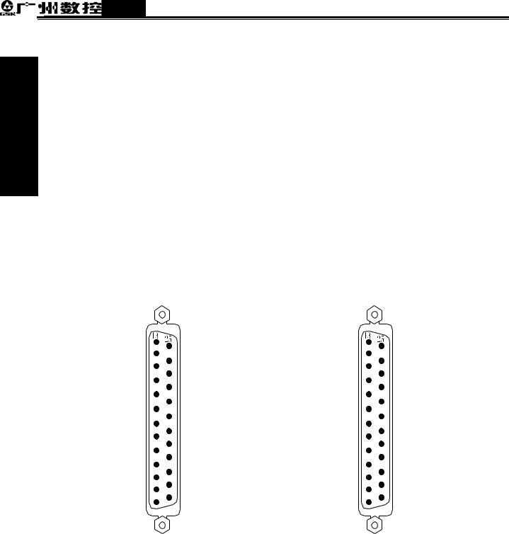
2.1.1 X Address in I/O Interface
zAddress range: X0000.0 X0003.7 are separately distributed to CNC XS40 and XS41 I/O interface.
zFixed address: X0000.3, X0000.5, X0001.3 separately corresponds to XDEC, ESP, ZDEC signal
which can be directly distinguished by CNC in CNC run.
Example: ESP signal is can be connected to X0000.5, CNC directly distinguishes signals on it and judge if there is ESP signal; CNC alarms to emergently stop when G8.4 signal is valid by PLC control.
Namely: CNC alarms to emergently stop when X0000.5 is 0;
CNC alarms to emergently stop when G8.4 is 0 by PLC control.
Input signal of fixed addresses
Signal |
Symbol |
Address |
Emergent stop signal |
ESP |
X0000.5 |
Deceleration signal of machine reference point return in X direction |
XDEC |
X0000.3 |
Deceleration signal of machine reference point return in Z direction |
ZDEC |
X0001.3 |
zDefinable address: their functions can be defined by user according to requirement and used for connecting with external electric circuit and ladder. Distribution graph of X address in I/O interface is as follows:
13 Y0001.7 |
25 COM |
13 X0002.1 |
25 COM |
|
12 Y0001.6 |
12 X0002.2 |
|||
24 COM |
24 COM |
|||
11 +24V |
11 +24V |
|||
23 +24V |
23 +24V |
|||
10 X0000.5 ESP |
10 X0002.3 |
|||
22 X0000.4 |
22 X0002.4 |
|||
9 X0001.3 ZDEC |
9 X0002.5 |
|||
21 X0001.2 |
21 X0002.6 |
|||
8 X0001.1 |
8 X0003.1 |
|||
20 X0001.0 |
20 X0003.2 |
|||
7 X0001.4 |
7 X0003.3 |
|||
19 X0001.5 |
19 X0003.4 |
|||
6 X0001.6 |
6 X0003.6 |
|||
18 COM |
18 COM |
|||
5 X0001.7 |
5 X0003.5 |
|||
17 COM |
17 COM |
|||
4 X0000.0 |
4 X0003.7 |
|||
16 COM |
16 COM |
|||
3 X0000.1 |
3 X0003.0 |
|||
15 COM |
15 COM |
|||
2 X0000.2 |
2 X0002.7 |
|||
14 COM |
14 COM |
|||
1 X0000.3 XDEC |
1 X0002.0 |
|||
|
|
XS40 female |
XS41 female |
2.1.2 X Address on Operator Panel
Address range: X0020.0 X0026.0 are fixed addresses which correspond to press keys on operator panel and which signal definitions cannot be changed by user.
-2

Chapter 2 |
Address |
|
|
Relationship between addresses and press keys is as follows:
X0020 |
7 |
6 |
5 |
4 |
3 |
2 |
1 |
0 |
Key |
SKIP |
SINGLE |
|
JOG |
|
|
AUTO |
EDIT |
|
|
|
MPG |
|
|
MDI |
|
|
|
|
|
|
|
|
|
X0021 |
7 |
6 |
5 |
4 |
3 |
2 |
1 |
0 |
|
|
|
|
|
|
|
MST |
MST |
Key |
|
|
|
|
|
|
DRY |
|
|
|
|
|
|
|
|
|
|
X0022 |
7 |
6 |
5 |
4 |
3 |
2 |
1 |
0 |
Key |
|
|
|
|
|
|
|
|
X0023 |
7 |
6 |
5 |
4 |
3 |
2 |
1 |
0 |
Key |
|
JOG |
|
|
|
|
|
|
CCW |
LUR. |
STOP |
COOLANT |
|
CW |
|
|
|
|
|
|
|
X0024 |
7 |
6 |
5 |
4 |
3 |
2 |
1 |
0 |
Key |
|
|
|
|
|
|
|
|
|
PAUSE |
|
|
|
|
|
|
TOOL |
X0025 |
7 |
6 |
5 |
4 |
3 |
2 |
1 |
0 |
Key |
|
|
|
|
|
|
|
RUN |
|
|
|
|
|
|
|
|
|
X0026 |
7 |
6 |
5 |
4 |
3 |
2 |
1 |
0 |
Key |
|
|
|
|
|
|
|
|
2.2 PLC→MACHINE ADDRESS Y
Programming 1 Book
980TD-PLC Y address are divided into two: Y0000.0 Y0003.7 are mainly distributed to CNC XS42 and XS39 I/O interfaces, including fixed address and definable address; Y0004.0 X0009.7 which are mainly distributed to indicators on the operator panel. Other addresses are reserved ones. Their values are 0 or 1.
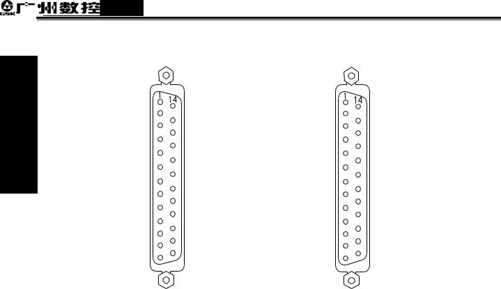
2.2.1 Y Address in I/O Interface
Address range: Y0000.0 Y0003.7 are separately distributed to CNC XS42 and XS39 I/O interfaces and their signal definitions can be defined by user according to requirements to connect to external
-3
GSK980TD Turning Machine CNC System
electric circuit and ladder.
Distribution graph of 980TD output interfaces address is as follows:
Programming 1 Book
1 Y0003.0 |
14 Y0003.1 |
1 Y0000.0 |
14 Y0000.1 |
|
2 Y0002.7 |
2 Y0000.2 |
|||
15 Y0002.5 |
15 Y0000.3 |
|||
3 Y0002.6 |
3 Y0000.4 |
|||
16 Y0002.4 |
16 Y0000.5 |
|||
4 Y0002.2 |
4 Y0000.6 |
|||
17 Y0002.3 |
17 Y0000.7 |
|||
5 Y0002.0 |
5 Y0001.0 |
|||
18 COM |
18 COM |
|||
6 Y0002.1 |
6 Y0001.1 |
|||
19 COM |
19 COM |
|||
7 Y0003.2 |
7 Y0001.2 |
|||
20 COM |
20 COM |
|||
8 Y0003.3 |
8 Y0001.3 |
|||
21 COM |
21 COM |
|||
9 Y0003.4 |
9 Y0001.4 |
|||
22 COM |
22 COM |
|||
10 Y0003.5 |
10 Y0001.5 |
|||
23 COM |
23 COM |
|||
11 Y0003.6 |
11 X0000.6 |
|||
24 COM |
24 COM |
|||
12 Y0003.7 |
12 X0000.7 |
|||
25 +24V |
25 +24V |
|||
13 +24V |
13 +24V |
|||
|
|
|||
|
XS42 male |
|
XS39 male |
2.2.2 Y Addresses on Operator Panel
Address range: Y0004.0 Y0009.0 are fixed addresses which correspond to indicators on the operator panel, and which signal definitions cannot be changed by user. Relationship corresponding to each state indicator is referred to Appendix2: Output signal(Y).
2.3 PLC→NC ADDRESS G
Address range: G0000.0 G0255.7, value range: 0 or 1. Refer to Appendix3: G, F signals about definitions of address signals.
2.4 NC→PLC ADDRESS F
Address range: F0000.0 F0255.7, value range: 0 or 1. Refer to Appendix3: G, F signal about definitions of address signals.
2.5 INTERNAL RELAY ADDRESS
Address range: R0000.0 R0999.7, value range: 0 or 1. They are zero after CNC is switched on.
-4

Chapter 2 |
Address |
|
|
Address
7 6 5 4 3 2 1 0
number R0000
R0001
Definable addresses
R0899
R0900
NC
R0999
2.6 INFORMATION DISPLAYING REQUEST ADDRESS A
Address range: A0000.0 A00024.7 and they are zero after CNC is switched on.
Address |
7 |
6 |
5 |
4 |
3 |
2 |
1 |
0 |
|
number |
|||||||||
|
|
|
|
|
|
|
|
||
A0000 |
|
|
|
|
|
|
|
|
|
A0001 |
|
|
|
|
|
|
|
|
|
|
|
|
|
|
|
|
|
||
|
|
|
|
|
|
|
|
|
A0024
2.7 HOLD RELAY ADDRESS K
Programming 1 Book
The address area is used for hold relay and setting PLC parameters and data are saved after the system is switched off. Address range: K0000.0 K0039.7, value range: 0 or 1.
Address
7 6 5 4 3 2 1 0
number K0000 K0001
Definable addresses
K0029
K0030
NC
K0039
-5
GSK980TD Turning Machine CNC System
Programming 1 Book
2.8 COUNTER ADDRESS C
The address area is used for storing current counting value of counter and data are saved after the system is switched off. Address range: C0000 C0099, value range: 0 21,4748,3647.
Address |
31 |
30 |
29 |
28 |
3 |
2 |
1 |
0 |
||
number |
||||||||||
|
|
|
|
|
|
|
|
|
||
C0000 |
|
|
|
|
|
|
|
|
|
|
C0001 |
|
|
|
|
|
|
|
|
|
|
|
|
|
|
|
|
|
|
|
||
|
|
|
|
|
|
|
|
|
|
|
C0099
2.9 COUNTER PRESET VALUE ADDRESS DC
The address area is used for storing preset value of counter and data are saved after the system is switched off. Address range: DC0000 DC0099, value range: 0 21,4748,3647.
Address |
31 |
30 |
29 |
28 |
3 |
2 |
1 |
0 |
||
number |
||||||||||
|
|
|
|
|
|
|
|
|
||
DC0000 |
|
|
|
|
|
|
|
|
|
|
DC0001 |
|
|
|
|
|
|
|
|
|
|
|
|
|
|
|
|
|
|
|
||
|
|
|
|
|
|
|
|
|
|
|
DC0099
2.10 TIMER ADDRESS T
The address area is used for storing current value of timer and T0000 T0079 are zero after the system is switched on.T0080 T0099 are saved after it is switched off. Value range: 0 21,4748,3647.
Address |
31 |
30 |
29 |
28 |
3 |
2 |
1 |
0 |
||
number |
||||||||||
|
|
|
|
|
|
|
|
|
||
T0000 |
|
|
|
|
|
|
|
|
|
|
T0001 |
|
|
|
|
|
|
|
|
|
|
|
|
|
|
|
|
|
|
|
||
|
|
|
|
|
|
|
|
|
|
|
T0099
-6
Chapter 2 |
Address |
|
|
2.11 TIMER PRESET VALUE ADDRESS DT
The address area is used for storing preset value of timer and data are saved after the system is switched off. Address range: DT0000 DT0099 and value range: 0 21,4748,3647.
Address |
31 |
30 |
29 |
28 |
3 |
2 |
1 |
0 |
|||
number |
|||||||||||
|
|
|
|
|
|
|
|
|
|
||
DT0000 |
|
|
|
|
|
|
|
|
|
|
|
DT0099 |
|
|
|
|
|
|
|
|
|
|
|
|
|
|
|
|
|
|
|
|
|
||
|
|
|
|
|
|
|
|
|
|
||
|
|
|
|
|
|
|
|
|
|
|
|
2.12 DATA LIST ADDRESS D
Programming 1 Book
D0000 D0299 are zero when CNC is switched on. D0300 D0999 are saved after it is switched off. Value range: 0 255.
Address |
7 |
6 |
5 |
4 |
3 |
2 |
1 |
0 |
|
number |
|||||||||
|
|
|
|
|
|
|
|
||
D0000 |
|
|
|
|
|
|
|
|
|
D0001 |
|
|
|
|
|
|
|
|
|
|
|
|
|
|
|
|
|
||
|
|
|
|
|
|
|
|
|
D0299
D0300
D0999
2.13 LABEL ADDRESS L
It is used for specifying jump target label in JMPB and LBL label.
Range: L0 L9999
2.14 SUBPROGRAM NUMBER P
It is used for specifying the target subprogram number to call in CALL and subprogram number in SP. Range: P0000 P9999
-7
Chapter 3 PLC Basic Instructions
Chapter 3 PLC BASIC INSTRUCTIONS
Basic instructions are used for editing sequential programs and executing 1-bit operation. There are basic instructions for GSK980TD PLC as follows:
Instruction |
Function |
Component |
name |
|
|
LD |
Read normally-open contact |
X, Y, F, G, R, K, A |
LDI |
Read normally-closed contact |
X, Y, F, G, R, K, A |
OUT |
Output coil |
Y, G, R, K, A |
AND |
Normally-open contact in series |
X, Y, F, G, R, K, A |
ANI |
Normally-closed contact in series |
X, Y, F, G, R, K, A |
OR |
Parallel normally-open contact |
X, Y, F, G, R, K, A |
ORI |
Parallel normally-closed contact |
X, Y, F, G, R, K, A |
ORB |
Parallel series circuit block |
|
ANB |
Parallel circuit block in series |
|
Programming 1 Book
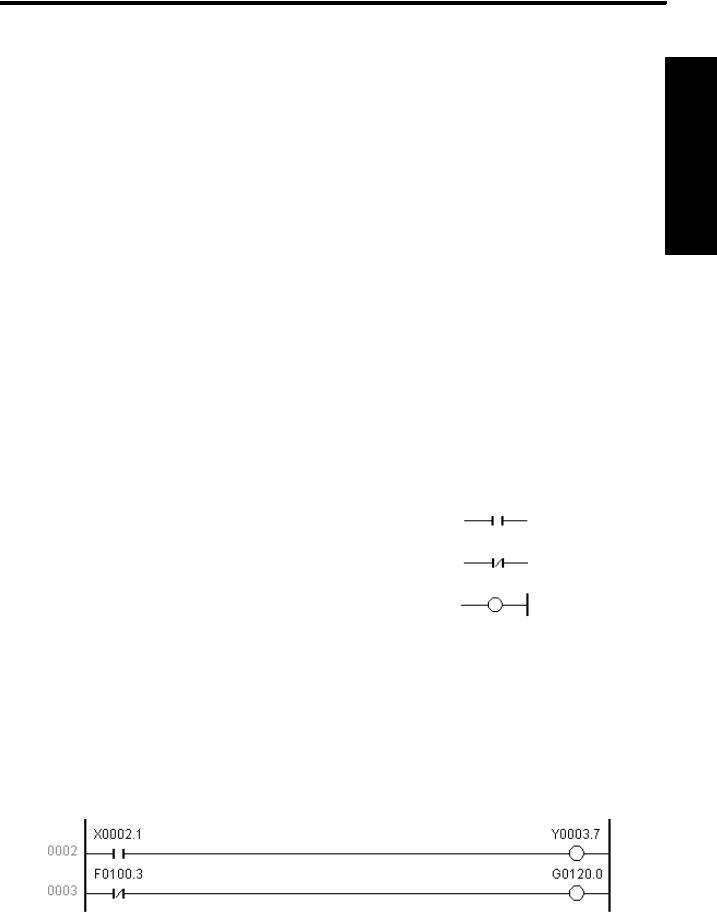
3.1 LD LDI OUT INSTRUCTION
● Mnemonic code and function
Mnemonic code |
Function |
Ladder symbol |
LD |
Read normally-open contact |
|
|
|
|
LDI |
Read normally-closed contact |
|
|
|
|
OUT |
Output coil |
|
|
|
|
●Instruction explanation
A:LD, LDI are used for connecting contact to bus bar. Each one can combine with instruction ANB and can be used at starting point of branch.
B:OUT is used for driving output relay, internal relay coil instead of input relay.
C:Parallel instruction OUT can be continuously used.
●Programming example
Program explanation
When X0002.1 is 1, the system outputs Y0003.7
When F0100.3 is 0, the system outputs G0120.0
-1
GSK980TD Turning Machine CNC System
ngimProgram 1 okBo
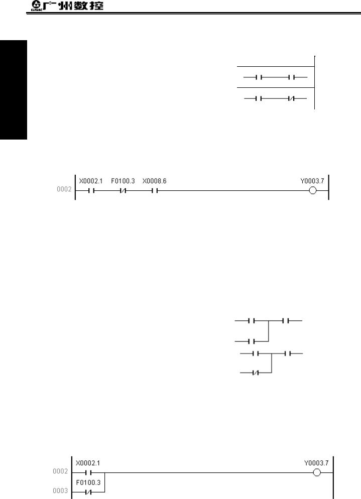
3.2 AND, ANI INSTRUCTION
● Mnemonic code and function |
|
|
|
|
Mnemonic code |
Function |
Ladder symbol |
|
AND |
Normally-open contact in series |
|
|
|
|
|
|
ANI |
Normally-closed contact in series |
|
|
|
|
|
● Instruction explanation
AND, ANI can connect one contact in serial. There can be many contacts in serial and the instructions can be used many times.
● Programming example
Program explanation
Use X0002.1,
Use F0100.3 and X0002.1 in series
Use X0008.6, and F0100.3 and X0002.1 in series
If X0002.1=1, X0008.6=1 and F0100.3 is 0, the system outputs Y0003.7.
3.3 OR, ORI INSTRUCTION
● Mnemonic code and function
Mnemonic code |
Function |
Ladder symbol |
OR |
Parallel normally-open contact |
|
|
|
|
ORI |
Parallel normally-closed contact |
|
|
|
|
●Instruction explanation
A:OR, ORI can be connected to one contact in parallel. When more than two contacts are connected in series and the serial loop is connected with other loop in parallel, the system should use ORB.
B:The system executes OR, ORI from its current step with LD, LDI in parallel.
●Programming example
-2
Chapter 3 PLC Basic Instructions
Program explanation
Use X0002.1
Use F0100.3 and X0002.1 in series
If X0002.1=1, and F0100.3 is 0, the system outputs Y0003.7.
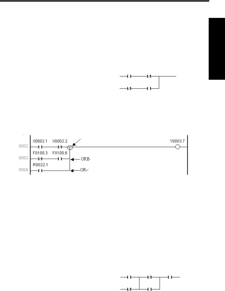
3.4 ORB INSTRUCTION
●Mnemonic code and function
Mnemonic code |
Function |
Ladder symbol |
ORB |
Parallel series circuit block |
|
|
|
|
●Instruction explanation
A:Serial loop block is defined to its loop combined by more than contacts in series. When the serial loop is connected in parallel, starting point of branch uses LD and its end point uses ORB.
B:ORB is sole instruction without address.
●Programming example
Programming 1 Book
Node
Program explanation
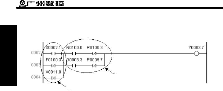
As above figure, there are three branches(0002,0003,0004) from left bus line to node, and 0002 and 0003 are serial circuit blocks. There is parallel serial circuit block between bus line and node or among nodes, the following ending of branch use ORB except for the first one. Use OR instruction if the branch 0004 is not serial circuit block.
ORB and ANB are instructions without operation function, representing or, and relationship among circuit blocks.
3.5 ANB INSTRUCTION
●Mnemonic code and function
Mnemonic code |
Function |
Ladder symbol |
ANB |
Parallel circuit block in series |
|
|
|
|
●Instruction explanation
A: Use ANB when the branch loop is serially connected with the previous loop. Use LD, LDI at the starting
-3
GSK980TD Turning Machine CNC System
point of branch, and use ANB to serially connect with the previous loop. B: ANB is sole instruction without address.
Programming 1 Book
● Programming example
Block 1
Block 2
Program explanation
As above ladder, ORB represents the parallel serial circuit block in block 2 and ANB represents block 1 and 2 in series.
-4
 Loading...