


 This user manual describes all proceedings concerning the operations of GS series AC servo products in details as much as possible. However, it is impractical to give particular descriptions for all unnecessary or unallowable system operations due to the manual text limit product specific applications and other causes. Therefore, the proceedings not indicated herein should be considered impractical or unallowable.
 This user manual is the property of GSK CNC Equipment Co., Ltd. All rights are reserved. It is against the law for any organization or individual to publish or reprint this manual without the express written permission of GSK and the latter reserves the right to ascertain their legal liability.

GS2000T Series AC Servo Drive Unit User Manual
Foreword
Dear user,
It’s our great pleasure for your patronage and selects our company products!
The capability, installation, connection, debugging, use as well as maintenance of
GS2000T series AC servo drive unit are described in this manual. In order to guarantee the product safety and the work can be effectively performed, the user must read carefully the manual before installing and using the drive unit.
To avoid the injury of the operators and the others, and the damage of the drive device, please pay special attention to the following alarms before reading this manual:
Danger |
Incorrect operation may result in death or severe |
|
|
|
injury. |
Caution |
Operating the machine incorrectly may result in |
|
|
|
injured or flesh wounded, as well as the loss in |
|
|
material. |
|
|
If the approved procedure is not observed, it may |
Notice |
||
|
|
result in the machine behaving unexpectedly. |
|
|
The vital requests and important indications are |
|
|
indicated during operating. |
|
|
It means Forbiddance (absolutely can not be done) |
It means Compulsion (must be done)
II

Safety Warnings
 Danger
III

GS2000T Series AC Servo Drive Unit User Manual
 Danger
 Caution
IV

Safety Warnings
 Caution
V

GS2000T Series AC Servo Drive Unit User Manual
Safety Responsibility
Manufacturer’s Responsibility
——Be responsible for the danger which should be eliminated and/or controlled on design and configuration of the provided Servo drive unit and accessories.
——Be responsible for the safety of the provided Servo drive unit and accessories.
——Be responsible for the provided information and advice for the users.
User’s Responsibility
——Be trained with the safety operation of Servo drive unit and familiar with the safety operation procedures.
——Be responsible for the dangers caused by adding, changing or altering to the original Servo drive units and the accessories.
——Be responsible for the failure to observe the provisions for operation, adjustment, maintenance, installation and storage in the manual.
All specifications and designs herein are subject to change without further notice.
This manual is reserved by end user.
We are full of heartfelt gratitude to you for supporting us in the use of GSK’s products.
VI
|
|
|
|
Contents |
|
|
|
|
|
|
|
|
Contents |
|
CHAPTER ONE |
PRODUCT INTRODUCTION............................................................. |
1 |
||
1.1 |
Basic Knowledge ................................................................................................................. |
1 |
||
1.2 |
The Confirmation of the Products Arrival ............................................................................. |
6 |
||
|
1.2.1 |
Servo Motor Model .................................................................................................... |
7 |
|
|
1.2.2 Servo drive unit model ............................................................................................... |
8 |
||
|
1.2.3 Servo drive unit appearance...................................................................................... |
9 |
||
1.3 |
Technical Specification ................................................................................................ |
12 |
||
|
1.3.1 Servo Motor Technical Specification........................................................................ |
12 |
||
|
1.3.2 The Technical Specification of Servo Drive Unit ...................................................... |
17 |
||
1.4 |
Order Guide ................................................................................................................. |
19 |
||
|
1.4.1 |
Model selection flow ................................................................................................ |
19 |
|
|
1.4.2 |
Order model example .............................................................................................. |
19 |
|
|
1.4.3 |
Standard configuration accessories......................................................................... |
22 |
|
CHAPTER TWO |
INSTALLATION .............................................................................. |
25 |
||
2.1 |
Servo Motor ....................................................................................................................... |
25 |
||
|
2.1.1 Installation Dimension of the Servo Motor ............................................................... |
25 |
||
|
2.1.2 Installation of the servo motor.................................................................................. |
28 |
||
2.2 |
Servo drive unit.................................................................................................................. |
29 |
||
|
2.2.1 Installation dimension installation dimension ........................................................... |
30 |
||
|
2.2.2 |
Installation interval ................................................................................................... |
31 |
|
CHAPTER THREE CONNECTION ............................................................................ |
34 |
|||
3.1 |
Connection of Peripheral Equipment ................................................................................. |
34 |
||
3.2 |
Terminal connection of Main Circuit................................................................................. |
41 |
||
|
3.2.1 Main circuit connection of the servo drive unit ......................................................... |
41 |
||
|
3.2.2 Wiring of main circuit ............................................................................................... |
42 |
||
|
3.2.3 Interfaces explanations of servo motor .................................................................... |
42 |
||
3.3 |
Connection of Control Signal ............................................................................................. |
44 |
||
|
3.3.1 CN1 control signal layout......................................................................................... |
44 |
||
|
3.3.2 |
Speed command input............................................................................................. |
45 |
|
|
3.3.3 |
Position command input .......................................................................................... |
46 |
|
|
3.3.4 |
Switching value input ............................................................................................... |
49 |
|
|
3.3.5 |
Switching value output............................................................................................. |
51 |
|
|
3.3.6 |
Position feedback output ......................................................................................... |
54 |
|
3.4 |
Feedback Signal Connection ............................................................................................. |
56 |
||
|
3.4.1 CN2 interface of GS series D-SUB servo drive unit................................................. |
56 |
||
|
3.4.2 CN2 interface of GS series MDR servo drive unit.................................................... |
57 |
||
|
3.4.3 Connection of motor’s encoder feedback input........................................................ |
58 |
||
|
3.4.4 Connection of the 2nd position feedback input ......................................................... |
60 |
||
3.5 |
GSK-CAN Communication Function .................................................................................. |
62 |
||
3.6 |
Connection Sample in Working Modes .............................................................................. |
64 |
||
|
3.6.1 Connection in speed working mode......................................................................... |
64 |
||
|
3.6.2 Connection in position working mode ...................................................................... |
66 |
||
VII

|
|
|
|
GS2000T Series AC Servo Drive Unit |
User Manual |
|
|
|
|
|
|
CHAPTER FOUR |
DISPLAY AND OPERATION ........................................................ |
68 |
|||
4.1 |
Operation Panel................................................................................................................. |
68 |
|||
4.2 |
Menu Display..................................................................................................................... |
69 |
|||
4.3 |
State Monitoring................................................................................................................. |
70 |
|||
4.4 |
Parameter Setting.............................................................................................................. |
72 |
|||
4.5 |
Parameter Management .................................................................................................... |
74 |
|||
CHAPTER FIVE |
DEBUGGING................................................................................... |
77 |
|||
5.1 |
Manual, JOG Operation..................................................................................................... |
78 |
|||
|
5.1.1 |
Manual run............................................................................................................... |
79 |
||
|
5.1.2 |
Jog run..................................................................................................................... |
80 |
||
5.2 |
Run in Speed Mode ........................................................................................................... |
81 |
|||
|
5.2.1 External analog voltage command .......................................................................... |
81 |
|||
|
5.2.2 |
Internal speed command ......................................................................................... |
83 |
||
5.3 |
Run in Position Mode......................................................................................................... |
85 |
|||
CHAPTER SIX |
FUNCTION DEBUGGING.................................................................. |
88 |
|||
6.1 |
Basic Performance Parameter Debugging ........................................................................ |
88 |
|||
6.2 |
HOLD Release Signal Application ..................................................................................... |
90 |
|||
6.3 |
Switching the Motor Rotation Directions ............................................................................ |
93 |
|||
6.4 |
Function Debugging of Position Mode ............................................................................... |
95 |
|||
|
6.4.1 Electronic Gear Ratio of Position Commands.......................................................... |
95 |
|||
|
6.4.2 |
Position Arrival Signal.............................................................................................. |
96 |
||
|
6.4.3 |
Pulse offset clear CLE ....................................................................................... |
97 |
||
|
6.4.4 |
Pulse command prohibition INH ........................................................................ |
98 |
||
6.5 |
Function Debugging in Speed Mode.................................................................................. |
98 |
|||
|
6.5.1 |
Analog Command Adjustment ................................................................................. |
98 |
||
|
6.5.2 |
Speed Arrival Signal ................................................................................................ |
99 |
||
|
6.5.3 |
Zero-speed Clamping ............................................................................................ |
100 |
||
CHAPTER SEVEN |
PARAMETER ............................................................................ |
101 |
|||
7.1 |
Parameter Table .............................................................................................................. |
101 |
|||
Chapter Eight |
ABNORMALITY and TROUBLESHOTTING ................................... |
109 |
|||
8.1 |
Abnormality for Abnormal Operations.............................................................................. |
109 |
|||
|
8.1.1 |
Speed mode .......................................................................................................... |
109 |
||
|
8.1.2 |
Position mode........................................................................................................ |
110 |
||
8.2 |
Alarms and Remedies ..................................................................................................... |
111 |
|||
8.3 |
Remedies for not Displaying Alarm Code ........................................................................ |
116 |
|||
8.4 |
Inspection and Maintenance............................................................................................ |
118 |
|||
Appendix A Model Code Parameters and Motors Table......................................... |
119 |
||||
Appendix B |
Peripheral Equipment ........................................................................ |
121 |
|||
B.1 |
External brake resistor .................................................................................................... |
121 |
|||
B.2 Circuit Breaker and Contactor (Necessary)..................................................................... |
122 |
||||
B.3 Three-phase AC filter (recommended) ............................................................................ |
122 |
||||
B.4 |
Isolation transformer (necessary) .................................................................................... |
123 |
|||
VIII

Chapter One Product Presentation
CHAPTER ONE PRODUCT INTRODUCTION
1.1Basic Knowledge
¾Fundamental of AC Servo Drive Unit
The AC Servo Drive Unit is composed of the AC servo drive unit and the AC servo motor (Three-phase permanent magnet synchronous servo motor, hereinafter referred to as Servo motor). The drive unit is treated the three-phase AC integrated current as AC current (i.e. AC DC), and ON or OFF of the power switch tube is controlled, the approximate sine wave current (that is DC—AC) of the phase potential difference 120° may occur in the three-phase stator winding of the servo motor. A rotation magnetic field is formed of this current in the servo motor, and the servo motor rotor may be introduced a sensitive current based on the rotation magnetic filed, the electromagnetic torque drive motor rotor rotation may create based on the interaction between the rotation magnetic field and the induction current. The higher the current frequency of the servo motor winding is, the faster the speed of the servo motor is; the higher current magnitude of amplitude value of the servo motor winding is, the bigger the torque (torque=force × arm length) output by the servo motor is.
The main circuit frame is shown in Fig. 1-1, and PG described in the figure is an encoder.
Fig. 1-1 Main circuit frame of servo drive unit
¾The basic structure of the AC servo drive device
The drive unit accepts the speed (or position) command of the control equipment (It is also called PC) including the CNC. The frequency and magnitude of the servo motor winding current can be controlled, so that the speed (or corner) of the servo motor rotor approximates the speed (or position) command value, and the error between the actual value of the servo motor rotor speed (corner) and the command value which can be gained by examining the encoder of servo motor. The frequency and magnitude of the current flowing through the servo motor winding is continuously adjusted by the servo motor, so that the error between the actual value of servo motor rotor speed (or corner) and command value which should be controlled within the required range. The basic structure of the servo system is shown in Fig. 1-2.
1

GS2000T Series AC Servo Drive Unit User Manual
CNC equipment
Given
|
Control |
Power drive unit |
Motor |
Driving |
|
unit |
machine |
||
|
|
|
||
|
|
|
|
|
|
|
Feedback |
|
|
|
|
check |
|
|
Fig.1-2 The basic structure of AC servo device
¾The general concept of control
Control: It is called control that the process making the characters (for example: speed) of the object (for example: servo motor) reach or approximate the anticipated value, and the former object is called as the controlled; the character of the controlled object is regarded as controlled amount, and the unit to be achieved which is called controllable unit; the expected value (command value) of the controlled amount received from the control unit is called the given; the controlled amount is assumed to the input of control unit, which is affected the process of controlled amount, is called the feedback, check the unit of being controlled amount is called feedback unit. The feedback can be divided into positive (same direction) and negative (reverse direction) based upon the controlled amount and the given direction output by the control unit. The drive equipment is composed of the control unit controlled by the controllable amount, the controlled object and the feedback unit. Drive units can be divided into closed-loop and open-loop equipments in terms of whether there is feedback unit or not or the position of the feedback unit in the drive unit. The closed-loop control equipments introduced in this manual are all negative feedback.
In the AC servo drive equipment introduced in this manual, the drive unit is control unit, the servo motor is controlled object, the motor speed (the corner of rotor) is controlled amount, the servo motor encoder is feedback unit, and the actual speed of the encoder motor detection is used for speed control to achieve the speed feedback. Therefore, the AC servo drive belongs to the close-loop control equipment.
z Open-loop control equipment: A feedback unit is not performed in control equipment, and the actual value of controlled amount is not affected to the output of control unit. For example, the step motor drive equipment, the rotor of stepper motor should be varied from the current phase-sequence changes after the stepper motor drive unit outputs the current phase-sequence and changes. Generally, the motor rotor may not follow the current phase-sequence when the overload occurs or the high acceleration/deceleration issues, due to the step motor does not install speed or position feedback unit, eventually, the “step-out” may cause.
Open-loop control is shown in Fig.1-3.
2
Chapter One Product Presentation
Fig.1-3 Open-loop control
zClosed-loop control: The controlled amount of the control equipment is detected by the feedback unit and sent to the control unit, and the control equipment changes the controlled variable through controlling the output of the control unit. The close-loop control equipment is divided into the full closed-loop control equipment and the semi-closed-loop control equipment based upon the check position of feedback unit. The feedback unit directly detects the controlled amount for feedback which is called the complete closed-loop control equipment (see Fig. 1-4), and the mechanical position is regarded as the controlled amount, the grating rule installed on the machine is regarded as a position feedback unit, and the encoder mounted on the servo motor is treated as a speed feedback unit, and then the equipment achieves a full closed-loop control in the mechanical position. If the grating rule is not mounted, the encoder of servo motor is simultaneously regarded as the position and speed feedback unit (see Fig. 1-5). Therefore, this is a semi-closed-loop control equipment of a machine position.
Fig. 1-4 Full closed-loop control equipment
Fig. 1-5 Semi-closed-loop control equipment
z PID control: It is also called PID adjustment, which is common calculation of control unit is treated the mathematical treatment for the input data (given, feedback). P is proportional, which is indicated that both input and output of control unit are composed of the linear proportional relation, the bigger the proportional control coefficient is, the more sensitive the system reacts, the less steady-state errors is (it can not be eliminated). The system vibration and unsteadiness may occur due to the excessive proportional control coefficient. “I” means integral, it is indicated that the input of the control unit is affected to the time integral output
3

GS2000T Series AC Servo Drive Unit User Manual
(the input is gradually affected the output), the bigger the integral time constant is, the more steady the system is, and the steady-state error can be eliminated, but the system may respond slowly. “D” means differential, it is indicated that the input differential (input the changeable slope) is affected to the output. The differential control can be forecasted the error, produced the advancing check function and reduce the follow error, as well improved the dynamic capability. The vibration and steadiness may cause due to the excessive differential coefficient. The proportion, integral and differential are interacted. The PID control parameters are adjusted to the balance for the system reaction rate, control accuracy and steadiness. Because the differential adjust is easily caused by the impact and vibration, the servo drive in the manual adopts PI adjustment, that is the proportion and integral are performed only.
¾The concepts related to serve control
Three kinds of basis control modes of the servo drive equipment are available, such as: position, speed and torque. Its frame is shown in Fig.1-6.
z Position control: The motor rotation direction and angle are given by using the numerical pulse or data communication mode, the drive unit controls motor rotor that rotates a corresponding angle in terms of the given direction. The rotation angle (position) and speed can be controlled.
z Speed control: The motor rotation direction and speed are given by using the analog voltage or data communication mode, the drive unit controls the motor rotor that rotates based upon the given direction and speed.
z Torque control: The output torque size and direction are given by using the analog voltage or data communication mode, the rotor rotation direction and torque output size of motor are controlled by the drive unit.
Currently, the servo drive device introduced in the manual does not accept the signal given from torque, the torque control operation mode is not offered temporarily.
|
Position |
|
Speed |
|
Current |
|
|
|
|
controller |
|
controller |
|
controller |
|
|
|
|
|
Position |
|
Speed |
|
Current |
Power |
Motor |
|
|
adjustment |
|
adjustment |
|
adjustment |
amplification |
|
Command |
|
|
|
|
||||
|
Position |
|
|
|
|
|
|
|
position |
|
|
Speed feedback |
|
Current feedback |
|
|
|
|
feedback signal |
|
signal |
|
signal |
|
PG |
|
|
|
|
|
|
|
|||
Fig. 1-6 Tricyclic control system frame
¾Servo drive unit performance index
Servo drive unit dynamic response characteristic: the reaction speed, dynamic control error and stable control error of the servo drive equipment are performed when the specification or the load is changed. Fig. 1-7 is the response characteristic figure in which the servo drive device offers a step signal. (The actual line is given signal, and the broken line is the output signal of the drive unit equipment, same as below):
4

Chapter One Product Presentation
Fig. 1-7 Servo dynamic response curve
Rising time tr: It means that the time that the rotation output amount is risen from zero for the first time to 90% of steady-state value R (t) , and it also means the dynamic response rapidity. Regulation time ts: The ±5 of steady-state value near to the step response curve steady-state value R (t) is regarded as the allowance error area. The required least time is the adjust time that the responding curve arrival does not overstep the error area, It is measured the regulation processing speed of the equipment.
Overshoot σ: It indicates that the speed output amount exceeds the rate between maximum speed D-value (Rmax (t)-R (t)) and stationary-state value R (t), it reflects relative stability of a servo device, and it also can be expressed by the percentage, that is:
σ(%) = Rmax (t) − R(t) ×100%
R(t)
Steady-state error: The D-value of the equipment between the expected output steady-state value and the actual output value are performed, after the equipment response is entered to the rotational speed.
Servo drive equipment static capability: In the drive control equipment, it is very important to stability. The steady-state capability index of servo drive equipment is a positioning accuracy, to be exact, the different degree between the actual and expectative states are generated when the device transition is ended. The reasons affecting the servo drive device steady-state accuracy is both the errors of the position measure device and the system error, which is regardless of the structure and parameter of the system. The position servo static curve is shown in Fig.1-8.
5

GS2000T Series AC Servo Drive Unit User Manual
Fig. 1-8 Position servo static curve
Follow error: It is indicated that the position difference between the moved worktable position (command position) required by the command signal and the actual moved worktable position, that is, the fellow error = (the command position value) – (the value of actual position).
Servo rigid: The servo drive unit is caused position error capability against the load interference.
1.2The Confirmation of the Products Arrival
Check each item after receiving the products immediately, if any problems, please contact the supplier or our company freely.
Checked item |
Remark |
|
|
|
|
Check the drive unit and servo motor, |
It is confirmed by the drive unit and servo motor’s |
|
which are the ordered products; |
nameplate. |
|
|
|
|
|
Confirm the content of packing list, if this content is |
|
Check whether the fittings are assembled; |
inconsistent with the accessories, and refer to the |
|
|
section 1.4 for the order instruction. |
|
|
|
|
Check whether the products are damaged |
The integrated appearance of the products should |
|
due to the transportation; |
be complete and without damage. |
|
|
|
|
Check whether the screws are loose. |
Check whether the screws are loose with the |
|
screwdriver |
||
|
||
|
|
1. The damaged AC servo drive unit or the incomplete accessories can not be
mounted;
2. The AC drive unit should be matched with the servo motor;
3. GS2000T series products is divided into the D-SUB and MDR based on its interface types, and they must meet the requirements.
6

Chapter One Product Presentation
1.2.1 Servo Motor Model
Servo motor model:
#1 Working power supply of safe brake is DC, 0.9 1.1 ×24V the interface is 3-core socket, 1, 2 pin are power supply terminals, 3 pin is an earthing terminal. When 1, 2 pins are turned on, the safe brake is not activated; when they are turned off, it is activated, and the safe brake time is ≤0.1s.
#2 Using three digits 150 means its value is three digits 150×10-1=15 its unit is N·m. #3 ‘□’ means the digital code, and some digit means the special shaft extension needs to
consider the installation appearance figure of the motor.
7

GS2000T Series AC Servo Drive Unit User Manual
1.2.2Servo drive unit model
Name plate sample:
Model explanation:
“GS” series servo drive unit, G GSK S SERVO.
Voltage class code, 2 220V 3 380V 4 440V.
Power component nominal current, 3 digits means 025,030,045,050,075,100 unit A , the leading zero cannot be omitted.
Adaptive motor model: T adaptive to synchronous servo motor; Y adaptive to asynchronous servo motor.
Communication bus code, N no bus; C GSK-CAN bus; L GSK-Link bus. Feedback(encoder) interface model code, P only adaptive incremental encoder; A adaptive to absolute encoder, without standby battery; B adaptive to absolute
encoder, without standby battery(used to circle count of memory absolute encoder when power off).
B adaptive to absolute encoder, with standby battery.
Feedback (encoder)interface allocation code which is presented by one digit. ‘1’ means there is only the motor feedback(1st position feedback) input interface CN2 ;
‘2’ means the motor feedback input CN2 and the 2nd position feedback input interface CN3 .
8

Chapter One Product Presentation
Position feedback signal interface model and allocation table:
|
|
Feedback encoder interface model, allocation explanation |
|
|
|
|
|
|
1 |
There is only the motor feedback input interface, adaptive to incremental |
|
|
encoder and there is no the 2nd position feedback input interface. |
||
P |
|
||
2 |
There are two position feedback input interfaces, adaptive to incremental |
||
|
|||
|
encoder. |
||
|
|
||
|
|
|
|
|
|
There is only the motor feedback input interface, adaptive to incremental and |
|
|
1 |
absolute encoder(be compatible with Biss, TAMAGAWA communication |
|
|
protocol which can be identified automatically), and there is no the 2nd position |
||
A |
|
||
|
feedback input interface. |
||
B |
|
||
|
|
||
|
There are two position feedback input interface, adaptive to incremental |
||
|
|
||
|
2 |
encoder and absolute encoder ( be compatible with Biss, and TAMAGAWA |
|
|
|
communication protocol which can be identified automatically). |
|
|
|
|
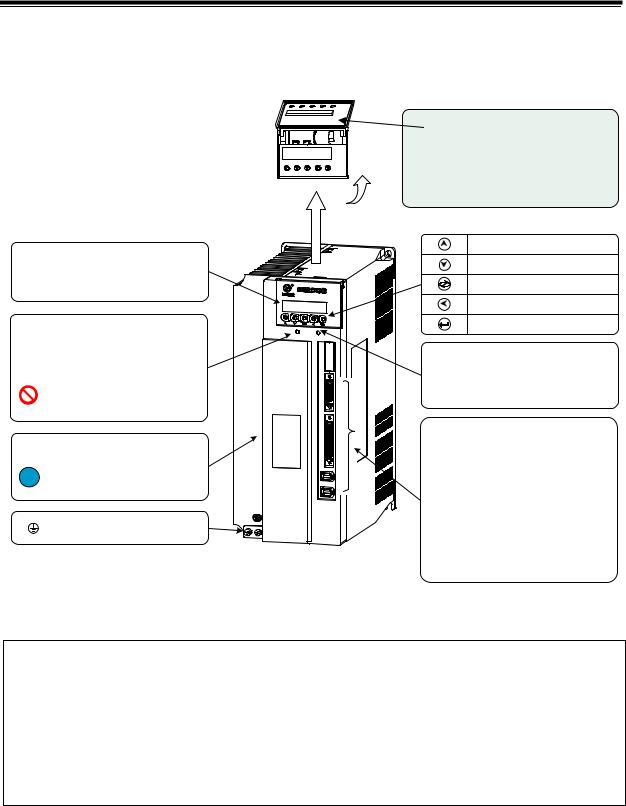
1.2.3Servo drive unit appearance
GS series AC servo drive unit is divided into the D-SUB and MDR series products according to the signal interfaces, uses the servo drive unit with D-SUB interfaces provided by WIESON, which is the D-SUB product, allocated with an incremental motor, and without GSK-CAN bus; uses the drive unit with high density interface provided by 3M, which is the MDR product, be compatible with absolute encoder motor, and with GSK-CAN bus.
zGS series AC servo drive unit appearance D-SUB
D-SUB products of GS series AC servo drive unit: GS2025T-NP1, GS2030T-NP1, GS2045T-NP1, GS2050T-NP1, GS2075T-NP1, GS2100T-NP1, which are adaptive to incremental encoder motor.
9

GS2000T Series AC Servo Drive Unit User Manual
Open cover plate
R
S
T
P
B1
B
U
V W r t
 220V MOTOR BRAKE 220V
Wiring terminals of main circuit
!Carefully check the product brand, R, S, T, r, t input power supply voltage, the motor’s lines are connected U, V,W correctly according to the marked!
Fig.1-9 GS series D-SUB product appearance
10
Chapter One Product Presentation
zGS series AC servo drive unit appearance MDR
MDR products of GS series AC servo drive unit: GS2030T-CA1, GS2050T-CA1, GS2075T-CA1, GS2100T-CA1 which are adaptive to absolute encoder motor.
Installation position for standby
battery for absolute encoder.(See
the drive unit model explanation).
Fig. 1-10 GS series MDR product
 GS series AC servo drive unit is divided into D-SUB and MDR products according to
different control signals, the D-SUB products are allocated with incremental encoder motors without GSK-CAN bus; the MDR products are allocated with the absolute encoder motor, with high precision and GSK-CAN bus.
The user selects the motor according to the motor’s precision when it orders.
11

GS2000T Series AC Servo Drive Unit User Manual
1.3Technical Specification
1.3.1Servo Motor Technical Specification
Table 1-1 Main technical parameter of 80SJT series motor
Model |
80SJT-M024C |
80SJT-M024E |
|
80SJT-M032C |
|
80SJT-M032E |
Item |
|
|
|
|
|
|
Rated power kW |
0.5 |
0.75 |
|
0.66 |
|
1.0 |
|
|
|
|
|
|
|
Pole-pairs |
|
|
|
4 |
|
|
|
|
|
|
|
|
|
Rated current A |
3 |
4.8 |
|
5 |
|
6.2 |
|
|
|
|
|
|
|
Zero-speed torque |
2.4 |
2.4 |
|
3.2 |
|
3.2 |
|
|
|
|
|
|
|
Rated torque N·m |
2.4 |
2.4 |
|
3.2 |
|
3.2 |
|
|
|
|
|
|
|
Max. torque N·m |
7.2 |
7.2 |
|
9.6 |
|
9.6 |
|
|
|
|
|
|
|
Rated speed r/min |
2000 |
3000 |
|
2000 |
|
3000 |
|
|
|
|
|
|
|
Max. speed r/min |
2500 |
4000 |
|
2500 |
|
4000 |
|
|
|
|
|
|
|
Rotation inertia kg·m2 |
0.83×10⁻⁴ |
0.83×10⁻⁴ |
|
1.23×10⁻⁴ |
|
1.23×10⁻⁴ |
Weight kg |
2.8 |
2.9 |
|
3.4 |
|
3.5 |
|
|
|
|
|
|
|
Insulation grade |
|
F GB |
755—2008 |
|
|
|
|
|
|
|
|||
Vibration grade |
|
R GB 10068—2008 |
|
|||
|
|
|||||
Guard grade |
IP65 GB 4208—2008/IEC 60529 2001 GB/T 4942.1—2006 |
|||||
|
|
|||||
Installation type |
IMB5 flanged installation GB/T 997—2008 / IEC 60034-7:2001 |
|||||
|
|
|
|
|||
Working hour |
|
S1 continuous working GB 755—2008 |
|
|||
|
|
|
|
|
|
|
Safe brake |
|
|
|
none |
|
|
Adaptive encoder |
Incremental 2500 p/r, 5000 p/r absolute encoder17bit single-circle or multi-circle. |
|||||
|
|
|
|
|
|
|
The following is torque character diagram T M of one rotation of the servo motor , A: continuous working area; B: short time working area.
12
|
|
|
|
|
|
|
Chapter One |
Product Presentation |
|
|||
|
|
|
|
|
|
|
|
|
|
|
|
|
|
|
Table 1-2 Main technical parameters of 110SJT series, 130SJT series motor |
|
|||||||||
|
|
|
|
|
|
|
|
|
|
|
|
|
|
|
|
Type |
110SJT-M |
110SJT-M |
110SJT-M |
|
110SJT-M |
130SJT-M |
130SJT-M |
|
|
|
Item |
|
|
|
|
|
||||||
|
|
|
|
040D |
040E |
060D |
|
060E |
040D |
050D |
|
|
|
|
|
|
|
|
|
||||||
|
|
|
|
|
|
|
|
|
|
|||
|
Rated power kW |
1.0 |
1.2 |
1.5 |
|
1.8 |
1.0 |
1.3 |
|
|||
|
|
|
|
|
|
|
|
|
|
|
|
|
|
Pole-pairs |
|
|
|
|
|
4 |
|
|
|
|
|
|
|
|
|
|
|
|
|
|
||||
|
Rated current A |
4.5 |
5 |
7 |
|
8 |
4 |
5 |
|
|||
|
|
|
|
|
|
|
|
|
|
|||
|
Zero-speed torque(N·m) |
4 |
4 |
6 |
|
6 |
4 |
5 |
|
|||
|
|
|
|
|
|
|
|
|
|
|
|
|
|
|
N·m |
|
4 |
4 |
6 |
|
6 |
4 |
5 |
|
|
|
Rated torque |
|
|
|
|
|||||||
|
|
|
|
12 |
10 |
12 |
|
12 |
10 |
12.5 |
|
|
|
Max. torque N·m |
|
|
|
|
|
||||||
|
Rated speed/min |
|
2500 |
3000 |
2500 |
|
3000 |
2500 |
2500 |
|
||
|
|
|
|
|
|
|
|
|
|
|||
|
Max. speed r/min |
3000 |
3300 |
3000 |
|
3300 |
3000 |
3000 |
|
|||
|
|
|
|
|
|
|
|
|
|
|||
|
Rotation inertia(kg·m2 |
0.68×10⁻³ |
0.68×10⁻³ |
0.95×10⁻³ |
|
0.95×10⁻³ |
1.1×10⁻³ |
1.1×10⁻³ |
|
|||
|
Weight kg |
6.1 |
6.1 |
7.9 |
|
7.9 |
6.5 |
6.5 |
|
|||
|
|
|
|
|
|
|
|
|
|
|||
|
Motor weight with safe |
7.7 |
7.7 |
9.5 |
|
9.5 |
8.1 |
8.1 |
|
|||
|
brake kg |
|
|
|
|
|
||||||
|
|
|
|
|
|
|
|
|
|
|
|
|
|
|
|
|
|
|
|
|
|
||||
|
Insulation grade |
|
|
F GB 755-2008 |
|
|
|
|||||
|
|
|
|
|
|
|
|
|||||
|
Vibration grade |
|
|
R GB 10068-2008 |
|
|
|
|||||
|
|
|
|
|
|
|
|
|
|
|||
|
Guard grade |
|
|
|
|
IP65 GB/T4942.1-2006 |
|
|
|
|||
|
|
|
|
|||||||||
|
Installation type |
IMB5 flanged installation GB/T 997-2008 / IEC 60034-7:2001 |
|
|||||||||
|
|
|
|
|
|
|
||||||
|
Working hour |
|
|
S1 Continuous working GB 755-2008 |
|
|
||||||
|
|
|
|
|||||||||
|
Adaptive encoder |
Incremental 2500 p/r, 5000 p/r absolute encoder 17bit single-circle or multi-circle. |
|
|||||||||
|
|
|
|
|
|
|
|
|
|
|
|
|
The following is torque character diagram T M of one rotation of the servo motor , A: continuous working area; B: short time working area.
|
110SJT-MO40D |
|
|
|
|
110SJT-MO40E |
|
|
|
|
110SJT-MO60D |
|
|
|||
Speed r/min |
|
|
|
|
Speed r/min |
|
|
|
|
Speed r/min |
|
|
|
|||
3000 |
|
|
|
|
|
3600 |
|
|
|
|
|
3000 |
|
|
|
|
|
|
|
|
|
|
|
|
|
|
|
|
|
|
|||
2000 |
|
|
|
|
|
2700 |
|
|
|
|
|
2000 |
|
|
|
|
|
|
|
|
|
|
A |
B |
|
|
|
|
|
|
|
||
|
A |
B |
|
|
|
1800 |
|
|
|
|
A |
B |
|
|
||
1000 |
|
|
|
900 |
|
|
|
|
|
1000 |
|
|
||||
|
|
|
|
|
|
|
|
|
|
|
|
|
|
|
|
|
|
|
|
|
|
|
0 |
|
|
|
|
|
|
|
|
|
|
0 |
4.0 |
8.0 |
12.0 |
4.0 |
8.0 |
12.0 |
0 |
4.0 |
8.0 |
12.0 |
||||||
|
|
Torque N·m |
|
|
Torque N·m |
|
|
Torque N·m |
||||||||
|
110SJT-MO60E |
|
|
|
|
130SJT-MO40D |
|
|
|
|
130SJT-MO50D |
|
|
|||
Speed r/min |
|
|
|
|
Speed r/min |
|
|
|
|
Speed r/min |
|
|
|
|||
3600 |
|
|
|
|
|
3000 |
|
|
|
|
|
3000 |
|
|
|
|
|
|
|
|
|
|
|
|
|
|
|
|
|
|
|||
2700 |
|
|
|
|
|
|
|
|
|
|
|
2000 |
|
|
|
|
|
A |
B |
|
|
|
2000 |
|
|
|
|
|
|
|
|
|
|
1800 |
|
|
|
|
A |
B |
|
|
|
|
A |
B |
|
|
||
900 |
|
|
|
|
|
1000 |
|
|
|
1000 |
|
|
||||
|
|
|
|
|
|
|
|
|
|
|
|
|
|
|
|
|
0 |
|
|
|
|
|
|
|
|
|
|
|
|
|
|
|
|
4.0 |
8.0 |
12.0 |
0 |
4.0 |
8.0 |
12.0 |
|
0 |
4.0 |
8.0 |
12.0 |
|||||
|
|
|
|
|
|
|
||||||||||
|
|
Torque N·m |
|
|
Torque N·m |
|
|
Torque N·m |
||||||||
13

|
|
|
GS2000T Series AC Servo Drive Unit |
User Manual |
||||||
|
|
|
|
|
|
|
|
|
|
|
|
Table 1-2(continuous) |
Main technical parameters of 110SJT series, 130SJT series motor |
||||||||
|
|
|
|
|
|
|
|
|
|
|
|
Type |
130SJT-M |
|
130SJT-M |
130SJT-M |
|
130SJT-M |
130SJT-M |
130SJT-M |
|
|
Item |
|
|
|||||||
|
060D |
|
075D |
100B |
|
100D |
150B |
|
150D |
|
|
|
|
|
|
||||||
|
|
|
|
|
|
|
|
|
|
|
|
Rated power kW |
1.5 |
|
1.88 |
1.5 |
|
2.5 |
2.3 |
|
3.9 |
|
|
|
|
|
|
|
|
|
|
|
|
Pole-pairs |
|
|
|
|
4 |
|
|
|
|
|
|
|
|
|
|
|
|
|
||
|
Rated current A |
6 |
|
7.5 |
6 |
|
10 |
8.5 |
|
14.5 |
|
|
|
|
|
|
|
|
|
|
|
|
Zero-speed torque |
6 |
|
7.5 |
10 |
|
10 |
15 |
|
15 |
|
N·m |
|
|
|
||||||
|
|
|
|
|
|
|
|
|
|
|
|
|
|
|
|
|
|
|
|
|
|
|
Rated torque N·m |
6 |
|
7.5 |
10 |
|
10 |
15 |
|
15 |
|
|
|
|
|
|
|
|
|
|
|
|
Max. torque N·m |
18 |
|
20 |
25 |
|
25 |
30 |
|
30 |
|
|
|
|
|
|
|
|
|
|
|
|
Rated speed/min |
2500 |
|
2500 |
1500 |
|
2500 |
1500 |
|
2500 |
|
|
|
|
|
|
|
|
|
|
|
|
Max. speed r/min |
3000 |
|
3000 |
2000 |
|
3000 |
2000 |
|
3000 |
|
|
|
|
|
|
|
|
|
|
|
|
Rotation inertia |
1.33×10⁻³ |
|
1.85×10⁻³ |
2.42×10⁻³ |
|
2.42×10⁻³ |
3.1×10⁻³ |
|
3.6×10⁻³ |
|
2 |
|
|
|
||||||
|
kg·m |
|
|
|
|
|
|
|
|
|
|
Weight kg |
7.2 |
|
8.1 |
9.6 |
|
9.7 |
11.9 |
|
12.7 |
|
|
|
|
|
|
|
|
|
|
|
|
Motor weight with safe |
10.1 |
|
11 |
12.5 |
|
12.6 |
14.8 |
|
15.6 |
|
brake kg |
|
|
|
||||||
|
|
|
|
|
|
|
|
|
|
|
|
|
|
|
|
|
|
|
|
|
|
|
Insulation grade |
|
|
|
F GB 755-2008 |
|
|
|
||
|
|
|
|
|
|
|
|
|
||
|
Vibration grade |
|
|
|
R GB 10068-2008 |
|
|
|
||
|
|
|
|
|
|
|
|
|
||
|
Guard grade |
|
|
|
IP65 GB/T4942.1-2006 |
|
|
|
||
|
|
|
||||||||
|
Installation type |
IMB5 flanged installation GB/T 997-2008 / IEC 60034-7:2001 |
||||||||
|
|
|
|
|
|
|
||||
|
Working hour |
|
|
S1 continuous working GB 755-2008 |
|
|
||||
|
|
|
||||||||
|
Adaptive encoder |
Incremental 2500 p/r, 5000 p/r, absolute encoder 17bit single-circle or multi-circle. |
||||||||
|
|
|
|
|
|
|
|
|
|
|
The following is torque character diagram T M of one rotation of the servo motor , A: continuous working area; B: short time working area.
14

Chapter One Product Presentation
|
Table 1-3 |
Main technical parameters of 175SJT series motor |
||||
|
|
|
|
|
|
|
Type |
175SJT-M120E |
175SJT-M150B |
175SJT-M150D |
175SJT-M180B |
175SJT-M180D |
|
Item |
|
|
|
|
|
|
Rated power kW |
3 |
2.4 |
3.1 |
2.8 |
3.8 |
|
|
|
|
|
|
|
|
Pole-pairs |
|
|
3 |
|
|
|
|
|
|
|
|
|
|
Rated current A |
13 |
11 |
14.5 |
15 |
16.5 |
|
|
|
|
|
|
|
|
Zero-speed torque |
12 |
15 |
15 |
18 |
18 |
|
N·m |
||||||
|
|
|
|
|
||
|
|
|
|
|
|
|
Rated torque N·m |
9.6 |
15 |
12 |
18 |
14.5 |
|
|
|
|
|
|
|
|
Max. torque N·m |
19.2 |
30 |
24 |
36 |
29 |
|
|
|
|
|
|
|
|
Rated speed/min |
3000 |
1500 |
2500 |
1500 |
2500 |
|
|
|
|
|
|
|
|
Max. speed r/min |
3300 |
2000 |
3000 |
2000 |
3000 |
|
|
|
|
|
|
|
|
Rotation inertia kg·m2 5.1×10⁻³ |
5.1×10⁻³ |
5.1×10⁻³ |
6.5×10⁻³ |
6.5×10⁻³ |
||
|
|
|
|
|
|
|
Weight kg |
18.9 |
18.5 |
19 |
22.8 |
22.9 |
|
|
|
|
|
|
|
|
Motor weight with safe |
24.5 |
24.1 |
24.6 |
28.4 |
28.5 |
|
brake kg |
||||||
|
|
|
|
|
||
|
|
|
|
|
|
|
Insulation grade |
|
|
F GB 755-2008 |
|
|
|
|
|
|
|
|
||
Vibration grade |
|
|
R GB 10068-2008 |
|
||
|
|
|
|
|||
Guard grade |
|
IP65 GB/T4942.1-2006 |
|
|||
|
|
|||||
Installation type |
IMB5 flanged installation GB/T 997-2008 / IEC 60034-7:2001 |
|||||
|
|
|
|
|||
Working hour |
|
S1 continuous working GB 755-2008 |
|
|||
|
|
|||||
Adaptive encoder |
Incremental 2500 p/r, 5000 p/r, absolute encoder17bit single-circle or multi-circle |
|||||
|
|
|
|
|
|
|
The following is torque character diagram T M of one rotation of the servo motor , A: continuous working area; B: short time working area.
15

|
|
|
GS2000T Series AC Servo Drive Unit |
User Manual |
|||||
|
|
|
|
|
|
|
|
|
|
|
Table 1-3(continuous) Main technical parameters of 175SJT series motor |
||||||||
|
|
|
|
|
|
|
|
|
|
|
Type |
175SJT-M220B |
175SJT-M220D |
|
175SJT-M300B |
|
175SJT-M300D |
175SJT-M380B |
|
|
Item |
|
|
|
|
|
|
|
|
|
Rated power kW |
3.5 |
4.5 |
|
3.8 |
|
|
6 |
6 |
|
|
|
|
|
|
|
|
|
|
|
Pole-pairs |
|
|
3 |
|
|
|
|
|
|
|
|
|
|
|
|
|
|
|
|
Rated current A |
17.5 |
19 |
|
24 |
|
|
27.5 |
29 |
|
|
|
|
|
|
|
|
|
|
|
Zero-speed torque |
22 |
22 |
|
30 |
|
|
30 |
38 |
|
N·m |
|
|
|
|||||
|
|
|
|
|
|
|
|
|
|
|
|
|
|
|
|
|
|
|
|
|
Rated torque N·m |
22 |
17.6 |
|
24 |
|
|
24 |
38 |
|
|
|
|
|
|
|
|
|
|
|
Max. torque N·m |
44 |
35.2 |
|
48 |
|
|
48 |
76 |
|
|
|
|
|
|
|
|
|
|
|
Rated speed/min |
1500 |
2500 |
|
1500 |
|
|
2500 |
1500 |
|
|
|
|
|
|
|
|
|
|
|
Max. speed r/min |
2000 |
3000 |
|
2000 |
|
|
3000 |
1800 |
|
|
|
|
|
|
|
|
|
|
|
Rotation inertia |
9.0×10⁻³ |
9.0×10⁻³ |
|
11.2×10⁻³ |
|
|
11.2×10⁻³ |
14.8×10⁻³ |
|
2 |
|
|
|
|||||
|
kg·m |
|
|
|
|
|
|
|
|
|
Weight kg |
28.9 |
29.2 |
|
34.3 |
|
|
34.4 |
42.4 |
|
|
|
|
|
|
|
|
|
|
|
Motor weight with |
34.5 |
36.8 |
|
42 |
|
|
42.1 |
50.1 |
|
safe brake kg |
|
|
|
|||||
|
|
|
|
|
|
|
|
|
|
|
|
|
|
|
|
|
|
|
|
|
Insulation grade |
|
|
|
B GB 755-2008 |
|
|
|
|
|
|
|
|
|
|
|
|||
|
Vibration grade |
|
|
F GB 10068-2008 |
|
|
|||
|
|
|
|
|
|||||
|
Guard grade |
|
IP65 GB/T4942.1-2006 |
|
|||||
|
|
|
|||||||
|
Installation type |
IMB5 flanged installation GB/T 997-2008 / IEC 60034-7:2001 |
|||||||
|
|
|
|
|
|||||
|
Working hour |
|
S1 continuous working GB 755-2008 |
|
|||||
|
|
|
|||||||
|
Adaptive encoder |
Incremental 2500 p/r, 5000 p/r, absolute encoder17bit single-circle or multi-circle. |
|||||||
|
|
|
|
|
|
|
|
|
|
The following is torque character diagram T M of one rotation of the servo motor , A: continuous working area; B: short time working area.
16

|
|
|
|
|
|
Chapter One |
Product Presentation |
||||||
|
|
|
|
|
|
|
|
|
|
|
|
|
|
|
1.3.2 Technical Specification of Servo Drive Unit |
|
|
|
|
|
|
|
|
||||
|
|
|
|
|
|
|
|
|
|
|
|
|
|
|
Drive unit type |
GS2025T |
GS2030T |
|
GS2045T |
|
GS2050T |
|
|
GS2075T |
GS2100T |
||
|
|
|
|
|
|
|
|
|
|
|
|
|
|
|
Rated current of adaptive |
I≤4 |
4 I≤6 |
|
6 I≤7.5 |
|
7.5 I≤10 |
|
|
10 I≤15 |
15 I≤29 |
||
|
servo motor A |
|
|
|
|
||||||||
|
|
|
|
|
|
|
|
|
|
|
|
|
|
|
|
|
|
|
|
|
|
|
|
|
|
|
|
|
Outline size mm |
|
90×190×182 |
|
|
112×230×182 |
|
120×270×218 |
130×305×248.5 |
||||
|
W×H×D |
|
|
|
|
||||||||
|
|
|
|
|
|
|
|
|
|
|
|
|
|
|
|
|
|
|
|
|
|
|
|||||
|
Main power supply |
|
3-phase AC(0.85 1.1)220V50/60Hz Remark 1 |
|
|
||||||||
|
|
|
|
|
|||||||||
|
Brake resistance |
Built-in brake resistance optionally external |
|
External brake resistance without |
|||||||||
|
|
brake resistance |
|
|
|
|
|
built-in brake resistance |
|||||
|
|
|
|
|
|
|
|
||||||
|
|
|
|
|
|
|
|
|
|
|
|
|
|
|
Timing ratio |
|
|
|
|
|
5000 1 |
|
|
|
|
|
|
|
|
|
|
|
|
|
|
|
|||||
|
Speed fluctuation rate |
|
|
|
rated speed×0.01%; |
|
|
|
|||||
|
|
|
|
|
|
|
|
|
|
|
|
|
|
|
Speed frequency response |
|
|
|
|
|
≥300Hz |
|
|
|
|
|
|
|
|
|
|
||||||||||
|
Working mode |
|
Manual, Jog, Internal Speed, External Speed, Position. |
||||||||||
|
|
|
|||||||||||
|
Internal speed mode |
The servo motor driven by the servo drive unit runs with the speed(speed closed-loop |
|||||||||||
|
control) set by the internal parameter,3-section speed is selected by the input signal. |
||||||||||||
|
|
||||||||||||
|
|
|
|||||||||||
|
External speed mode |
The servo motor driven by the servo drive unit runs with the speed(speed closed-loop |
|||||||||||
|
control) set by the external analog voltage speed command. |
|
|
||||||||||
|
|
|
|
||||||||||
|
|
|
|
|
|
|
|
|
|
|
|
|
|
|
External speed command |
|
10V +10V or 0V +10V is selected by the parameter. |
||||||||||
|
mode |
|
|||||||||||
|
|
|
|
|
|
|
|
|
|
|
|
|
|
|
|
|
|||||||||||
|
|
The servo motor driven by the servo drive unit runs based on the position command |
|||||||||||
|
|
pulse(position closed-loop control), the direction and the quantity of the position |
|||||||||||
|
Position mode |
command pulse determine the rotary direction and the angle of the servo motor’s rotor, |
|||||||||||
|
|
and the frequency of the position command pulse determines the speed of the motor’s |
|||||||||||
|
|
rotor. |
|
|
|
|
|
|
|
|
|
|
|
|
|
|
|||||||||||
|
Position command pulse |
Pulse/direction, CCW pulse/CW pulse, A/B orthogonality pulse, max. pulse frequency: |
|||||||||||
|
mode |
1MHz. |
|
|
|
|
|
|
|
|
|
|
|
|
|
|
|||||||||||
|
Electronic gear of position |
Command pulse multiplier coefficient: 1 32767; command pulse division coefficient: |
|||||||||||
|
command |
1 32767. |
|
|
|
|
|
|
|
|
|
|
|
|
|
|
|||||||||||
|
Orientation precision |
±0.005°(adaptive 17bit absolute encoder ; ±0.018°(adaptive 5000-line incremental |
|||||||||||
|
|
|
|
|
|
encoder). |
|
|
|
|
|
||
|
|
|
|
|
|
|
|
|
|
|
|
||
|
|
|
|
||||||||||
|
|
|
GS2□□□T-NP□ D-SUB adaptive incremental encoder; |
||||||||||
|
Motor’s feedback input |
GS2□□□T-CA□ MDR adaptive absolute encoder compatible Biss, |
|||||||||||
|
|
two kinds of communication protocol of Tamagawa and incremental encoder. |
|||||||||||
|
|
|
|
||||||||||
|
The 2nd feedback |
|
GS2□□□T-NP2 D-SUB : adaptive incremental encoder; |
||||||||||
|
GS2□□□T-CA2 MDR :adaptive absolute encoder compatible Biss, |
||||||||||||
|
input(adaptive interface) |
||||||||||||
|
two kinds of communication protocol of Tamagawa and incremental encoder. |
||||||||||||
|
|
||||||||||||
|
|
|
|||||||||||
|
|
GS2□□□T-NP□ D-SUB : motor’s feedback input signal: 1:1 output; |
|||||||||||
|
Position feedback output |
GS2□□□T-CA□ MDR division output of motor’s feedback input signal; |
|||||||||||
|
|
|
|
motor rotating one-rotation corresponding to feedback |
|||||||||
|
|
|
|
|
|||||||||
|
|
|
|
|
output pulse range: 16 32767. |
|
|
||||||
|
|
|
|
||||||||||
|
Communication bus |
|
GS2□□□T-NP□ D-SUB : without communication bus; |
||||||||||
|
|
GS2□□□T-CA□ MDR GSK-CAN bus |
|
|
|||||||||
|
|
|
|
|
|||||||||
|
|
|
|||||||||||
|
Input signal |
Servo enabling, alarm clear, CCW prohibited, CW prohibited, CCW started, CW started, |
|||||||||||
|
zero-speed clamped, internal speed selection, selection 2. |
|
|
||||||||||
|
|
|
|
||||||||||
|
|
|
|
|
|
|
|
|
|
|
|
|
|
17

GS2000T Series AC Servo Drive Unit User Manual
Servo ready, servo alarm, position arrival/speed arrival, HOLD release, zero-speed output, Z-axis pulse (encoder zero-point) and so on.
Protection functions for overvoltage, undervoltage, overcurrent, overload, drive unit overheating, encoder overheating, overspeed, and position out-of-tolerance, brake abnormality, motor overheating.
5 keys can execute the operation including the manual, Jog, modifying, setting, writing-in and copying parameter.
6-bit LED displays the speed, current position, command pulse accumulation, position offset, motor’s torque, motor’s current, rotor’s absolute position, input/output signal state and so on.
Note: The motor which power is below 0.8KW can use single-phase 220V power supply input, and the drive unit’s performance will reduce.
1.It can use single-phase 220V input with the servo motor below 0.8Kw, but the performance of the drive unit will reduce.
2.CCW means the motor is counter clockwise when it is watched from the shaft extension end of its installation surface CCW-Counter Clockwise ;
CW means the motor is counter clockwise when it is watched from the shaft extension end of its installation surface CWClockwise .
3.“*” in the type of the servo drive unit means to the type code of the optional configuration function.
18

Chapter One Product Presentation
1.4Order Guide
1.4.1Model selection flow
Motor′s toque
Motor rated speed
Motor installation mode
Machining precision decides the adaptive encoder of the motor
Motor model
Drive unit model
Torque range: 2.4 38 N·m
A motor’s rated speed 1000r/min B motor’s rated speed 1500r/min C motor’s rated speed 2000r/min D motor’s rated speed 2500r/min E motor’s rated speed 3000r/min.
1.Select different installation dimension of 80,110,130,175
2.Select whether the motor is matched
with keyseat.
1.Be adaptive to 2500 lines incremental encoder, position precision is ±0.036°;
2.Be adaptive to 5000 lines incremental
encoder, position precision is ±0.018° 3. Be adaptive to 17bit absolute encoder,
position precision is ±0.005°.
Search models according to Section 1.4.2. Confirm the drive unit is the economical or popularized according to the adaptive CNC system. The present popularized servo is matched with GSK988T CNC system.
After the motor’s model is confirmed, the servo drive unit’s model is done according to the corresponding relationship described in Section 1.4.2.
1.4.2Order model example
1.GS series servo equipment (including SJT series AC servo motor order model is shown below:
GS servo drive unit model — SJT AC servo motor model
Example GS2030T-NP1—110SJT-M040D(A2)
Explanation Order GS2030T-NP1 AC servo drive unit and its matched 110SJT-M040D A2 AC servo motor, and its accessories are standard configurations See Section 1.4.3 .
2. GS series servo drive unit without AC servo motor order model is shown below:
GS servo drive unit model — AC servo motor model
Example GS2030T-NP1— 110SJT-M040D(A2)
Explanation: for only ordering the servo drive unit, the exfacotry parameters is based on the
19

GS2000T Series AC Servo Drive Unit User Manual
servo motor allocation described in the brackets, and the accessories are standard configurations (see Section 1.4.3).
GS2000T-NP1 D-SUB series products matched with SJT series servo motors:
|
|
Servo motor parameters |
|
|
||
Drive unit model |
|
|
|
|
|
|
Motor model |
Rated |
Rated |
Rated |
Rated |
Encoder |
|
|
power |
current |
torque |
speed |
||
|
|
|
||||
|
|
|
|
|
|
|
GS2030T-NP1 |
110SJT-M040D(A2) |
1.0kW |
4.5A |
4N·m |
2500r/min |
5000 lines |
110SJT-MZ040D(A2) |
increment |
|||||
|
|
|
|
|
|
|
GS2030T-NP1 |
110SJT-M040E(A2) |
1.2kW |
5A |
4N·m |
3000r/min |
Incremental |
|
110SJT-MZ040E(A2) |
|
|
|
|
5000 lines |
GS2045T-NP1 |
110SJT-M060D(A2) |
1.5kW |
7A |
6N·m |
2500r/min |
Incremental |
|
110SJT-MZ060D(A2) |
|
|
|
|
5000 lines |
GS2050T-NP1 |
110SJT-M060E(A2) |
1.8kW |
8A |
6N·m |
3000r/min |
Incremental |
|
110SJT-MZ060E(A2) |
|
|
|
|
5000 lines |
GS2025T-NP1 |
130SJT-M040D(A2) |
1.0kW |
4A |
4N·m |
2500r/min |
Incremental |
130SJT-MZ040D(A2) |
5000 lines |
|||||
|
|
|
|
|
|
|
GS2030T-NP1 |
130SJT-M050D(A2) |
1.3kW |
5A |
5N·m |
2500r/min |
Incremental |
130SJT-MZ050D(A2) |
5000 lines |
|||||
|
|
|
|
|
|
|
GS2045T-NP1 |
130SJT-M060D(A2) |
1.5kW |
6A |
6N·m |
2500r/min |
Incremental |
130SJT-MZ060D(A2) |
5000 lines |
|||||
|
|
|
|
|
|
|
GS2050T-NP1 |
130SJT-M075D(A2) |
1.88kW |
7.5A |
7.5N·m |
2500r/min |
Incremental |
|
130SJT-MZ075D(A2) |
|
|
|
|
5000 lines |
GS2045T-NP1 |
130SJT-M100B(A2) |
1.5kW |
6A |
10N·m |
1500r/min |
Incremental |
|
130SJT-MZ100B(A2) |
|
|
|
|
5000 lines |
GS2050-TNP1 |
130SJT-M100D(A2) |
2.5kW |
10A |
10N·m |
2500r/min |
Incremental |
130SJT-MZ100D(A2) |
5000 lines |
|||||
|
|
|
|
|
|
|
GS2050T-NP1 |
130SJT-M150B(A2) |
2.3kW |
8.5A |
15N·m |
1500r/min |
Incremental |
|
130SJT-MZ150B(A2) |
|
|
|
|
5000 lines |
GS2075T-NP1 |
130SJT-M150D(A2) |
3.9kW |
14.5A |
15N·m |
2500r/min |
Incremental |
130SJT-MZ150D(A2) |
5000 lines |
|||||
|
|
|
|
|
|
|
GS2075T-NP1 |
175SJT-M180B(A2) |
2.8kW |
15A |
18N·m |
1500r/min |
Incremental |
|
175SJT-MZ180B(A2) |
|
|
|
|
5000 lines |
GS2100T-NP1 |
175SJT-M180D(A2) |
3.8kW |
16.5A |
14.5N·m |
2500r/min |
Incremental |
175SJT-MZ180D(A2) |
5000 lines |
|||||
|
|
|
|
|
|
|
GS2100T-NP1 |
175SJT-M220B(A2) |
3.5kW |
17.5A |
22N·m |
1500r/min |
Incremental |
|
175SJT-MZ220B(A2) |
|
|
|
|
5000 lines |
GS2100T-NP1 |
175SJT-M220D(A2) |
4.5kW |
19A |
17.6N·m |
2500r/min |
Incremental |
|
175SJT-MZ220D(A2) |
|
|
|
|
5000 lines |
GS2100-TNP1 |
175SJT-M300B(A2) |
4.7kW |
24A |
30N·m |
1500r/min |
Incremental |
|
175SJT-MZ300B(A2) |
|
|
|
|
5000 lines |
GS2100-TNP1 |
175SJT-M300D(A2) |
6kW |
27.5A |
24N·m |
2500r/min |
Incremental |
|
175SJT-MZ300D(A2) |
|
|
|
|
5000 lines |
20

Chapter One Product Presentation
GS2000T-CA1 MDR series products matched with SJT series servo motors:
|
|
Servo motor parameters |
|
|
|||
Drive unit model |
|
|
|
|
|
|
|
Motor model |
Rated |
Rated |
Rated |
|
Rated |
Encoder |
|
|
power |
current |
torque |
|
speed |
||
|
|
|
|
||||
|
|
|
|
|
|
|
|
GS2025T-CA1 |
80SJT-M024C(A4I) |
0.5kW |
3A |
2.4N·m |
|
2000r/min |
Absolute 17bit |
|
|
|
|
|
|
|
multi-circle |
GS2030T-CA1 |
80SJT-M024E(A4I) |
0.75kW |
4.8A |
2.4N·m |
|
3000r/min |
Absolute 17bit |
|
|
|
|
|
|
|
multi-circle |
GS2030T-CA1 |
80SJT-M032C(A4I) |
0.66kW |
5A |
3.2N·m |
|
2000r/min |
Absolute 17bit |
|
multi-circle |
||||||
|
|
|
|
|
|
|
|
GS2045T-CA1 |
80SJT-M032E(A4I) |
1.0kW |
6.2A |
3.2N·m |
|
3000r/min |
Absolute 17bit |
|
multi-circle |
||||||
|
|
|
|
|
|
|
|
GS2030T-CA1 |
110SJT-M040D(A4I) |
1.0kW |
4.5A |
4N·m |
|
2500r/min |
Absolute 17bit |
|
110SJT-MZ040D(A4I) |
|
|
|
|
|
multi-circle |
GS2045T-CA1 |
110SJT-M060D(A4I) |
1.5kW |
7A |
6N·m |
|
2500r/min |
Absolute 17bit |
110SJT-MZ060D(A4I) |
|
multi-circle |
|||||
|
|
|
|
|
|
|
|
GS2025T-CA1 |
130SJT-M040D(A4I) |
1.0kW |
4A |
4N·m |
|
2500r/min |
Absolute 17bit |
130SJT-MZ040D(A4I) |
|
multi-circle |
|||||
|
|
|
|
|
|
|
|
GS2030T-CA1 |
130SJT-M050D(A4I) |
1.3kW |
5A |
5N·m |
|
2500r/min |
Absolute 17bit |
130SJT-MZ050D(A4I) |
|
multi-circle |
|||||
|
|
|
|
|
|
|
|
GS2045T-CA1 |
130SJT-M060D(A4I) |
1.5kW |
6A |
6N·m |
|
2500r/min |
Absolute 17bit |
130SJT-MZ060D(A4I) |
|
multi-circle |
|||||
|
|
|
|
|
|
|
|
GS2050T-CA1 |
130SJT-M075D(A4I) |
1.88kW |
7.5A |
7.5N·m |
|
2500r/min |
Absolute 17bit |
|
130SJT-MZ075D(A4I) |
|
|
|
|
|
multi-circle |
GS2045T-CA1 |
130SJT-M100B(A4I) |
1.5kW |
6A |
10N·m |
|
1500r/min |
Absolute 17bit |
130SJT-MZ100B(A4I) |
|
multi-circle |
|||||
|
|
|
|
|
|
|
|
GS2050T-CA1 |
130SJT-M100D(A4I) |
2.5kW |
10A |
10N·m |
|
2500r/min |
Absolute 17bit |
|
130SJT-MZ100D(A4I) |
|
|
|
|
|
multi-circle |
GS2050T-CA1 |
130SJT-M150B(A4I) |
2.3kW |
8.5A |
15N·m |
|
1500r/min |
Absolute 17bit |
130SJT-MZ150B(A4I) |
|
multi-circle |
|||||
|
|
|
|
|
|
|
|
GS2075T-CA1 |
130SJT-M150D(A4I) |
3.9kW |
14.5A |
15N·m |
|
2500r/min |
Absolute 17bit |
130SJT-MZ150D(A4I) |
|
multi-circle |
|||||
|
|
|
|
|
|
|
|
GS2075T-CA1 |
175SJT-M150D(A4I) |
3.1kW |
14A |
12N·m |
|
2500r/min |
Absolute 17bit |
175SJT-MZ150D(A4I) |
|
multi-circle |
|||||
|
|
|
|
|
|
|
|
GS2075T-CA1 |
175SJT-M180B(A4I) |
2.8kW |
15A |
18N·m |
|
1500r/min |
Absolute 17bit |
175SJT-MZ180B(A4I) |
|
multi-circle |
|||||
|
|
|
|
|
|
|
|
GS2100T-CA1 |
175SJT-M180D(A4I) |
3.8kW |
16.5A |
14.5N·m |
|
2500r/min |
Absolute 17bit |
|
175SJT-MZ180D(A4I) |
|
|
|
|
|
multi-circle |
GS2100TCA1 |
175SJT-M220B(A4I) |
3.5kW |
17.5A |
22N·m |
|
1500r/min |
Absolute 17bit |
175SJT-MZ220B(A4I) |
|
multi-circle |
|||||
|
|
|
|
|
|
|
|
GS2100TCA1 |
175SJT-M220D(A4I) |
4.5kW |
19A |
17.6N·m |
|
2500r/min |
Absolute 17bit |
175SJT-MZ220D(A4I) |
|
multi-circle |
|||||
|
|
|
|
|
|
|
|
GS2100T-CA1 |
175SJT-M300B(A4I) |
4.7kW |
24A |
30N·m |
|
1500r/min |
Absolute 17bit |
175SJT-MZ300B(A4I) |
|
multi-circle |
|||||
|
|
|
|
|
|
|
|
21

|
|
GS2000T Series AC Servo Drive Unit |
User Manual |
|||||
|
|
|
|
|
|
|
|
|
|
|
|
|
|
|
|
|
|
|
|
|
Servo motor parameters |
|
|
|
||
|
Drive unit model |
|
|
|
|
|
|
|
|
Motor model |
Rated |
Rated |
Rated |
Rated |
Encoder |
|
|
|
|
power |
current |
torque |
speed |
|
||
|
|
|
|
|
||||
|
|
|
|
|
|
|
|
|
|
GS2100T-CA1 |
175SJT-M300D(A4I) |
6kW |
27.5A |
24N·m |
2500r/min |
Absolute 17bit |
|
|
175SJT-MZ300D(A4I) |
multi-circle |
|
|||||
|
|
|
|
|
|
|
|
|
|
GS2100T-CA1 |
175SJT-M380B(A4I) |
6 kW |
29 A |
38 N·m |
1500 r/min |
Absolute 17bit |
|
|
175SJT-MZ380B(A4I) |
multi-circle |
|
|||||
|
|
|
|
|
|
|
|
|
1.4.3Standard configuration accessories
The standard configuration accessories described in the following list are provided without the special requirements from the user. Please contact the sellers or allocate others after consulting our technical personnel when the user needs other accessories.
zGS2000T series D-SUB accessory list:
Order |
Name |
Model |
|
Quantity |
Explanation |
|
|
|
|
|
|
|
|
|
|
|
Encoder line of |
-00-761A |
|
1 line |
Standard length 3m |
|
|
|
motor |
|
|
|
|||
|
|
|
|
|
|
|
|
|
|
|
|
|
|
|
|
|
Power line of |
-00-765* note 1 |
|
1 line |
Standard length 3m |
|
|
|
motor |
|
|
|
|
|
|
Servo drive |
|
GS2000T Series AC |
|
|
|
|
|
unit, servo |
User Manual |
Servo Drive Unit |
User |
1 piece |
Technical documents |
|
|
motor and |
|
Manual |
|
|
|
|
|
CNC whole |
Brake resistor with |
|
|
|
Provided only when it is |
|
|
set |
RXLG800W15RJM |
1 piece |
adaptive to GS2075T-CA1 |
|
|
||
|
aluminium shell |
|
|
|
including 1m connection line |
||
|
|
|
|
|
|||
|
|
|
|
|
|
||
|
Brake resistor with |
|
|
|
Provided only when it is |
|
|
|
RXLG1200W10RJM |
1 piece |
adaptive to GS2100T-NP1 |
||||
|
aluminium shell |
|
|
|
including 1m connection line |
||
|
|
|
|
|
|||
|
|
|
|
|
|
|
|
Remark |
Control signal line of servo drive unit are provided with CNC: its standard length is |
||||||
3m. |
|
|
|
|
|
|
|
|
|
|
|
|
|
|
|
|
|
|
|
|
|
||
|
Connector plug |
DB44 pin socket |
|
1 set |
CN1 connector plug |
|
|
|
|
|
|
|
|
|
|
|
Encoder line of |
-00-761A |
|
1 line |
Standard length 3m |
||
|
motor |
|
|||||
|
|
|
|
|
|
|
|
|
|
|
|
|
|
|
|
|
Power line of |
-00-765* note 1 |
|
1 line |
Standard length 3m |
||
|
motor |
|
|
|
|
|
|
Servo drive |
|
GS2000T Series AC |
|
|
|
|
|
User Manual |
Servo Drive Unit |
User |
1 piece |
Technical documents |
|||
unit and |
|
Manual |
|
|
|
|
|
servo motor |
|
|
|
|
|
|
|
|
|
|
|
|
|
|
|
Brake resistor with |
|
|
|
Provided only when it is |
|||
|
|
|
|
||||
|
RXLG800W15RJM |
1 piece |
adaptive to GS2075T-CA1 |
||||
|
aluminium shell |
|
|
|
including 1m connection line |
||
|
|
|
|
|
|||
|
|
|
|
|
|
|
|
|
Brake resistor with |
|
|
|
Provided only when it is |
||
|
RXLG1200W10RJM |
1 piece |
adaptive to GS2100T-NP1 |
||||
|
aluminium shell |
|
|
|
including 1m connection line |
||
|
|
|
|
|
|||
|
|
|
|
|
|
|
|
22
 Loading...