


GSK928TE Turning CNC System User Manual
 The user manual describes all items concerning the operation of the system in detail as much as possible. However, it is
impractical to give particular descriptions of all unnecessary
and/or unavailable works of the system due to the length limit of
the manual, specific operations of the product and other causes.
Therefore, the operations not specified herein may be
considered impractical or unavailable.
 This user manual is the property of GSK CNC Equipment Co., Ltd. All rights reserved. It is against the law for any organization or
individual to publish or reprint this manual without the express written
permission of GSK and the latter reserves the right to ascertain their
legal liability.
1

GSK928TE Turning CNC System User Manual
Dear user,
We are really grateful for your patronage and purchase of GSK928 TE Turning CNC
system made by GSK CNC Equipment Co., Ltd.
Caution
This system can only be operated by authorized and qualified personnel as improper operations may cause accidents. Please carefully read this user
manual before use!
Before Use:
zConnect the emergency stop button of the system firmly and correctly, otherwise an emergency stop alarm will occur when switch on the system, so that the system cannot work properly.
zSet the reference point of the program of the system according to the actual mounting position of the tool of the machine that the system controls.
Note: The power supply of the system installed in the cabinet is exclusive to GSK’ CNC systems.
Must not take the power supply as other uses, otherwise, there maybe cause great accidence!
Chinese version of all technical documents in Chinese and English languages is regarded as final.
All specifications and designs are subject to change without notice.
All rights reserved.
We are full of heartfelt gratitude to you for supporting us in the use of GSK’s products.
2

GSK928TE Turning CNC System User Manual
|
|
|
|
|
Contents |
|
Suggestions for Safety ....................................................................................................................... |
|
1 |
||||
Operation.............................................................................................................................................. |
|
|
|
|
7 |
|
Chapter One |
Overview ................................................................................................................. |
7 |
||||
Chapter Two |
Technical Specifications........................................................................................ |
8 |
||||
Chapter Three |
Operator Panel..................................................................................................... |
9 |
||||
Chapter Four |
System Operation ............................................................................................... |
14 |
||||
4.1 |
System ON/OFF.................................................................................................................. |
14 |
||||
4.2 |
CNC System Operating Mode............................................................................................. |
15 |
||||
4.3 |
EDIT Mode........................................................................................................................... |
|
|
15 |
||
4.4 |
Manual Mode....................................................................................................................... |
|
28 |
|||
4.5 |
AUTO Mode......................................................................................................................... |
|
47 |
|||
4.6 |
Parameter Setting................................................................................................................ |
58 |
||||
4.7 |
Tool Offset Setting Mode ..................................................................................................... |
69 |
||||
4.8 |
Diagnosis............................................................................................................................. |
|
|
70 |
||
4.9 |
Alarm of Emergency Stop and Overtravel........................................................................... |
74 |
||||
4.10 Drive Unit Switch Control .................................................................................................. |
75 |
|||||
Programming |
..................................................................................................................................... |
|
|
|
76 |
|
Chapter 1 |
Programming Fundamentals ................................................................................... |
76 |
||||
1.1 |
Coordinate Axis and its Direction ........................................................................................ |
76 |
||||
1.2 |
Machine Zero....................................................................................................................... |
|
76 |
|||
1.3 |
Programming Coordinate .................................................................................................... |
76 |
||||
1.4 |
Workpiece Coordinate System............................................................................................ |
78 |
||||
1.5 |
Reference Point................................................................................................................... |
78 |
||||
Chapter 2 |
Program Structure..................................................................................................... |
79 |
||||
2.1 |
Character............................................................................................................................. |
|
|
79 |
||
2.2 |
Word .................................................................................................................................... |
|
|
|
79 |
|
2.3 |
Block Number...................................................................................................................... |
|
80 |
|||
2.4 |
Block .................................................................................................................................... |
|
|
|
80 |
|
2.5 |
Program Structure ............................................................................................................... |
80 |
||||
Chapter 3 Commands and their Functions .............................................................................. |
81 |
|||||
3.1 |
G commands |
— Preparatory Function .......................................................................... |
81 |
|||
3.2 |
M function |
— Miscellaneous Function............................................................................. |
113 |
|||
3.3 |
S function |
— Spindle Function ........................................................................................ |
118 |
|||
3.4 |
T Function |
— |
Tool Function .......................................................................................... |
119 |
||
3.5 |
F function |
— |
Feedrate Function .................................................................................. |
120 |
||
Chapter Four |
Programming Rules.......................................................................................... |
121 |
||||
I

|
|
|
Contents |
4.1 |
Some Commands in One Block ........................................................................................ |
121 |
|
4.2 |
Modal and Initial State of Commands ............................................................................... |
121 |
|
4.3 |
Other Rules ....................................................................................................................... |
122 |
|
4.4 |
Programming Example...................................................................................................... |
122 |
|
4.5 |
Alarm List........................................................................................................................... |
129 |
|
Appendix 1 GSKRS232 Communication Use......................................................................... |
132 |
||
Appendix 2 |
C5.1 FLASH Chip Copy and Check.................................................................. |
141 |
|
Connection....................................................................................................................................... |
|
143 |
|
Chapter One |
Interface .............................................................................................................. |
143 |
|
1.1 |
Interface Layout................................................................................................................. |
143 |
|
1.2 |
Total Frame........................................................................................................................ |
144 |
|
1.3 |
Total Connection Layout.................................................................................................... |
145 |
|
Chapter Two |
Interface Function .............................................................................................. |
146 |
|
2.1 |
Specifications..................................................................................................................... |
146 |
|
2.2 |
Interface Graph.................................................................................................................. |
147 |
|
Chapter Three CNC Device Connection ................................................................................. |
148 |
||
3.1 |
X1 Communication Interface............................................................................................. |
148 |
|
3.3 |
X3 Spindle Encoder Interface............................................................................................ |
150 |
|
3.4 |
X4 Tool Post Device Interface ........................................................................................... |
152 |
|
3.5 |
X5 Feed Drive Unit Interface............................................................................................. |
154 |
|
3.5.3.3 |
Pulse signal....................................................................................................................... |
155 |
|
3.6 |
X Switching Value Input Interface ..................................................................................... |
163 |
|
3.7 |
X7 Switching Value Output................................................................................................ |
165 |
|
3.8 |
X7 Spindle Converter Interface ......................................................................................... |
167 |
|
Appendix 1 |
GSK928TE Tool post Controller Circuit Diagram ......................................... |
170 |
|
Appendix 2 Interface Circuit Diagram..................................................................................... |
171 |
||
Appendix 3 Machine Zero Return Mode ................................................................................. |
174 |
||
Appendix 5 |
GSK928TE Integrated Wiring Table................................................................ |
177 |
|
Appendix 6 |
Appearance Installation Dimension of GSK928TE Turning CNC System.. 181 |
||
II

GSK928TE Turning CNC System User Manual
Suggestions for Safety
The user must carefully read the suggestions for the system before installing and operating the system.
The user must follow the suggestions of the system to ensure that the person is not hurt and the equipments are not damaged.
The user must follow the related suggestions for safety described in the manual, and must not operate it until the manual is read completely.
Follow safety instructions for the machine that the system will control. Do not run the machine until you have completely read both the instructions and this manual.
User must follow the suggestions of safety described in the user manual from the machine manufacture
User can operate the machine or compile the program to control the machine after completely reading the User Manual and the one from the machine manufacturer.
The power supply of the system installed in the cabinet is exclusive to GSK’ CNC systems. Must not take the power supply as other uses, otherwise, there maybe cause great accidence!
1
Safety Warning
.Graphic symbol
Caution Operation against the instructions may cause the operator serious injuries.
Alarm Wrong operation may injure the operator and damage the system.
Warning Improper operation may result in damage to the machine, as well its products. Important information
Shield
Earthing (PE)
Encoder
Coil of contact or relay
Exchange
Connecting terminal
2
GSK928TE Turning CNC System User Manual
. Notes
1 Check before acceptance
Warning ● The damaged or defect product must not be used.
2 Delivery and storage
Warning ●Moistureproof measures are needed while the system is delivered and stored. Never climb the packing box, neither stand on it, nor place heavy items on it. Do not put over five packing boxes in piles. Take particular care of the front panel and the display of the system.
3 Installation
 Warning ●Protect the system from sunlight and raindrops. The shell of the system is not waterproof.
 Warning ●Prevent dust, corrosive air, liquid, conductors and inflammable substances from entering the system.
●Keep the system away from inflammable and explosive substances. Avoid places where there is powerful electromagnetic interference.
●Install the system firmly without vibration.
4 Wiring
 Caution ●Only qualified persons can connect the system or check the connection. The connecting wires cannot be damaged. Do not press or open the cover of the system with power on.
 Caution ●The voltage and the polarity of connecting plugs must accord with the manual. ●Wet hands are dangerous to grasp the plug or the switch.
 Warning ●The connection must be proper and firm. ●The system must be earthed.
5 Debugging
 Warning ●Make sure that the parameters of the system is correct before the system runs. ●No parameter is beyond the setting limit in the manual.
3

Safety Warning
6 Operation
 Caution ●Only qualified operators can operate the system.
●Ensure the switch is OFF before connecting the power supply.
 Warning ●The operator can not leave the system to work alone.
●Do not switch on the system until making sure the connection is correct.
●The emergency stop button is able to disconnect all power supplies when the system breaks down. Do not switch on/off the system frequently
 Warning ●Prevent the system from the environmental interference.
7 Troubleshooting
 Caution ●Unqualified persons cannot repair the system.
 Warning ●After alarms, do not restart the system until the breakdown is fixed.
4

GSK928TE Turning CNC System User Manual
. Safety Suggestions for Programming
1 Setting a coordinate system
Incorrect coordinate system may cause the machine not to work as expected even if the program is correct, which may injure the operator, and damage the machine as well as its tool and workpiece.
2) Rapid traverse (positioning)
When G00 rapid traverse performs the positioning( nonlinear motion to position between its starting point and end point), make sure that the path for the tool is safe before programming. The positioning is to perform the rapid traverse, and when the tool and the workpiece are interfered, the tool, the machine and the workpiece may be damaged, and even the operator injured.
3) Applicability of user manual
The manual introduces in detail all functions of the system, including optional functions and max. controllable ranges, which are subject to change with the machine. If there is any doubt, please read the instruction for the machine
4) Functions of CNC system and machine
CNC machines depend on CNC systems, but also power voltage cabinets, servo systems, CNC and the operator panels. It is hard to explain all the integrated functions, programming and operation. Do not use integrated instructions not included in the manual until they have been tested successfully.
5

Safety Warning
. Notes and Safety Suggestions for Operating Machine
1 Test the machine without workpieces or tools. Make sure that the machine runs well before it starts to work.
2 Check the input data of the system carefully before operating the machine. Incorrect input data may cause the machine to work improperly, so as to damage the workpiece and the tool, as well injure the operator.
3 Make sure that the input feedrate of the system is suitable for the expected operation. Feedrate has a maximum for each machine, and the amount of the feed rate is subject to change with operation. Choose the maximum according to the instructions of the machine. Improper feedrate leads the machine to work wrongly, so as to damage the workpiece and the tool, as well injure the operator.
4 When tool compensation is needed, check the direction and the amount of the compensation. Improper compensation causes the machine to work wrongly, so as to damage the workpiece and the tool, as well injure the operator.
5 If the machine is to run in Manual mode, check the current position of the tool and the workpiece, and correctly specify the moving axis, moving direction and the feedrate. MPG(Handwheel) control with great override, such as 100, may damage the machine and its tool, even injure the operator.
6 If the tool is return to the reference point, make sure that the machine has been equipped with the device to detect the reference point, otherwise, the tool can not reach the reference point, which may damage the machine and its tool, and even injure the operator.
6
GSK928TE Turning CNC System User Manual
Operation
Chapter One Overview
With 480×240 lattice TFT color graphic LCD, GSK 928TE CNC system takes as key control the high-speed CPU and the complex programmable logic device of super-large-scale integrated circuits. ISO CNC code is used to write part programs. The system is characterized by μ-level precision control, a full screen editing, Chinese operation interface, real time demonstration of the machining process, and high cost-performance ratio. By means of programming, the system can be used to control stepper motors, so as to machine outer cylinders, end faces, grooves, tapers, circular arcs, and threads.
7

|
|
Operation |
Chapter Two System Operator Panel |
|
|
|
|
||
|
Chapter Two |
Technical Specifications |
||
2.1 |
Controlled axes |
2 (X, Z axis) |
|
|
2.2 |
Link axes |
2 (X, Z axis) |
|
|
2.3 |
Min. setting unit |
0.001 mm |
|
|
2.4 |
Min. motion unit |
X: 0.0005mm; Z: 0.001mm |
||
2.5 |
Max. dimension for programs |
±8000.000 mm |
||
2.6 |
Max. traverse rate |
15000 mm/min |
||
2.7 |
Feedrate |
5-6000 mm/min (G98/G99) |
||
2.8 |
Capacity of part program |
62KB |
|
|
2.9 |
Max. number of part programs |
100 |
|
|
2.1 |
Graphic LCD |
480×240 lattice TFT color LCD |
||
2.11 |
Communication interface |
Standard RS-232 |
||
2.12 |
Tool selection |
4 up to 8 |
||
2.13 |
Compensation |
Tool compensation, clearance compensation |
||
2.14 |
MPG(MPG) |
×0.001 ×0.01 ×0.1 |
||
|
|
S1, S2, S3, S4 direct output; S0 S15 output |
||
2.15 |
Spindle |
with BCD code; three automatic gear shifting with |
||
0 10V analog output; 1024p/r, 1200p/r spindle |
||||
|
|
|||
|
|
encoder available |
||
2.16 |
G codes |
24 codes including the fixed /compound cycles, Z |
||
threading |
|
|||
|
|
|
||
|
|
Metric/inch single and multiple straight, taper |
||
2.17 |
Thread functions |
thread, high-speed retraction with setting the |
||
|
|
retraction distance |
||
8

GSK928TE Turning CNC System User Manual
Chapter Three Operator Panel
928TE-II |
|
|
|
|
|
EDIT |
JOG |
AUTO |
PARAMETER |
OFFSET |
DIAGNOSIS |
Introduction of GSK 928TE Turning CNC System operator panel as follows:
3.1LCD display: CNC man-machine dialogue interface. Resolution 480×240 lattice TFT color
LCD display.
3.2Digit key: input all kind: Input all kinds of data 0-9 .
3.3Address keys Input English letters in word addresses of part programs.
3.4Function keys All function keys are based on Numerical Control of Machine-Symbol.
INCREASING RAPID OVERRIDE TRAVERSE OVERRIDE: Increase rapid traverse override in JOG mode and G00 rapid traverse override in AUTO mode.
REDUCING RAPID TRAVERSE OVERRIDE: Reduce rapid traverse override in JOG mode and G00 rapid traverse override in AUTO mode.
INCREASING FEEDRATE OVERRIDE: Increase feedrate override in JOG mode and G01 feedrate override in AUTO mode.
9

Operation |
Chapter Two System Operator Panel |
|
|
REDUCING FEEDATE OVERRIDE: Reduce feedrate override in JOG mode and G01
feedrate override in AUTO mode.
X PROGRAM REFERENCE POINT(PROGRAM ZERO) RETURN : It is valid in
JOG/AUTO mode.
Z PROGRAM REFERENCE POINT (PROGRAM ZERO) RETURN : It is valid in
JOG/AUTO mode.
 X MACHINE ZERO RETURN : It is valid in JOG/AUTO mode. whether machine zero is valid is defined by Bit7 of P12 .
 Z MACHINE ZERO RETURN: It is valid in JOG/AUTO mode. whether machine zero is valid is defined by Bit7 of P12 .
 DRY RUN: In AUTO mode, DRY RUN tests a program without G, S, M, and T functions output. In EDIT mode, moves the cursor directly to the first character behind the block number. The machine coordinate data become white from yellow besides LED ON after it is pressed.
 SINGLE BLOCK : A single block runs in AUTO mode.
 EDIT mode
 JOG mode
 AUTO mode
 PARAMETER mode
10
GSK928TE Turning CNC System User Manual
 OFFSET mode
 DIAGNOSIS mode
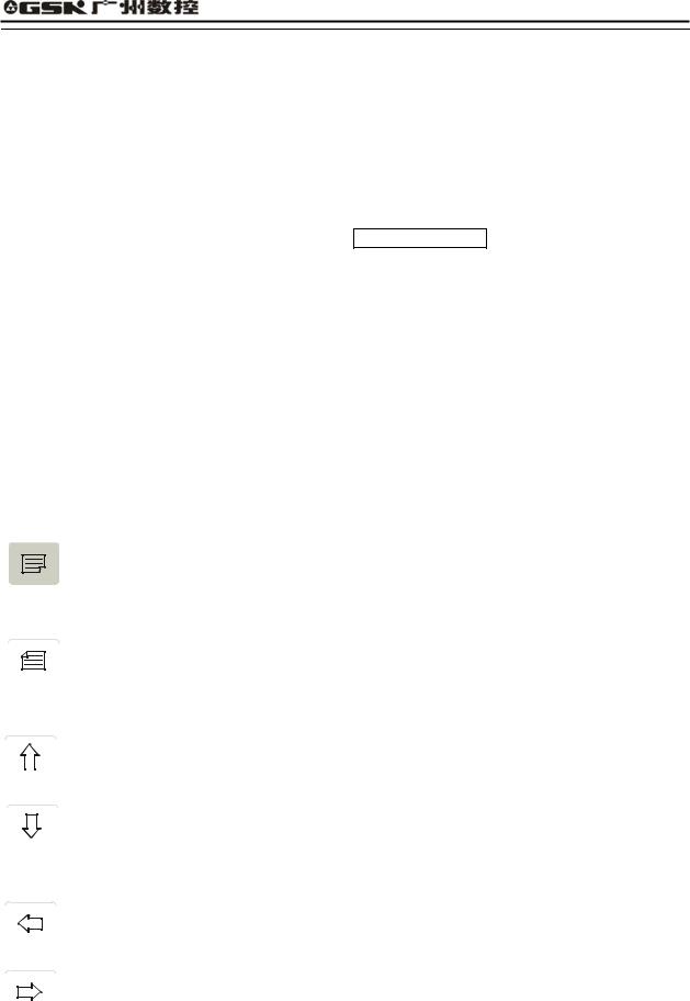
3.5Edit/state key
 Switch the input method in EDIT mode—- INSERT/REWRITE .
 Delete a number, a letter, a block or a whole program.
 Cancel the current input all kind of data or escape from the current operation state.
 Input all kind of data or select the required or run program or create a new part program.
 Press ENTER to confirmation.

 PAGE UP: page up to search programs or parameters in EDIT/PARAMETER/OFFSET operation mode.

 PAGE DOWN: page down to search programs or parameters in EDIT/ PARAMETER/ OFFSET mode.


 Cursor moving up the cursor moves up one line in EDIT/PARAMETER/OFFSET mode.


 Cursor moving down: the cursor moves down one line in EDIT/PARAMETER/OFFSET mode.


 Cursor moving left: the cursor moves one character position left in EDIT mode.


 Cursor moving right: the cursor moves one character position right in EDIT mode.
3.6Cycle start and feed hold button
11
Operation |
Chapter Two System Operator Panel |
Start and pause programs in AUTO mode.
 CYCLE START: Start to run programs in AUTO mode.
 FEED HOLD: Motor reduces to pause in JOG or AUTO mode.
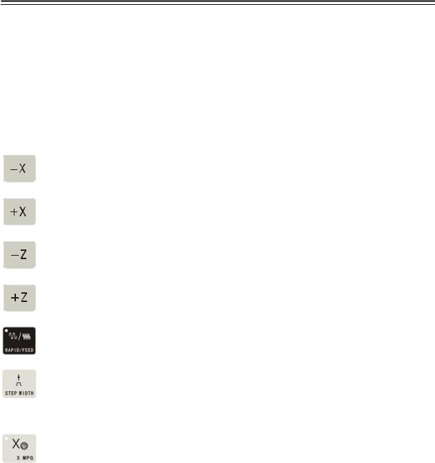
3.7 Manual axis control key
The selected axis and its direction in JOG mode:
X axis moves negatively in JOG mode.
X axis moves positively in JOG mode.
Z axis moves negatively in JOG mode.
Z axis moves positively in JOG mode.
RAPID TRAVERSE/FEED Switching rapid traverse and feed.
MANUAL STEP Selecting each step width or MPG feed in STEP/ MPG(Handwheel) mode.
X MPG(Handwheel) X motion is controlled by the MPG(Handwheel) (when the control is valid, other control keys related to the axis moving are invalid) .
 Z MPG Z motion is controlled by the MPG(Handwheel) (when the control is valid, other control keys related to the axis moving are invalid).
 STEP/JOG mode Switch STEP/JOG mode.
3.8Manual tool change and auxiliary function keys
Select directly the next tool number and control the machine to complete auxiliary functions as follows
12
GSK928TE Turning CNC System User Manual
Spindle rotation (CCW) |
Spindle rotates counterclockwise. |
Spindle stop |
Spindle stops. |
Spindle rotation (CW) |
Spindle rotates clockwise. |
Cooling control |
Cooling ON/OFF |
Spindle gear shifting |
Select the speed of each gear when the machine is equipped |
|
with multi-gear (up to 16 gears) spindle motor and control |
|
loops. |
Tool change |
Select the next tool number neighboring to the current one. |
Note The above-mentioned pressing keys are valid in JOG, AUTO and DIAGNOSIS mode when X, Z does not move, but only cooling control is valid.
3.9Reset key
System reset When the system resets, all axes stop motion, all auxiliary function
outputs are invalid, and the machine stops and returns to the initialization.
3.10 State indicator
It indicates the current state of CNC system. There are 15 function keys with LED indicator. When LED ON, its function of corresponding key is valid, otherwise it is invalid.
13
GSK928TE Turning CNC System User Manual
Chapter Four System Operation
This chapter introduces operations of GSK928TE Turning CNC system. Please read carefully before operation.
4.1 System ON/OFF
GSK928TE Turning CNC System is not equipped with the system power switch. User installs it according to the different machine to avoid bad effects to CNC system owing to the impaction of power supply.
CNC system is turned on as follows:
1.The master power switch of machine is turned on.
2.Connect with the power switch of the CNC system. Press 
 and the system displays GSK mark and caption, at the time, the system displays the software and hardware version number, delivery date by pressing other keys persistently except for the reset key.
CNC system is turned off as follows
1.The power switch of the CNC is turned off.
2.the power switch of the machine is turned off.
Note : The system should be initialized when it is turned on firstly.
The initialization operations are as follows:
Press the reset key and “9” key, and then release firstly the reset key and then “9” to enter the debugging window.
1.CNC PAR P01—P26 DY3
2.CNC PAR P01—P26 DA98
3.CLEAR PRO %00—%99
4.DEBUG
5.COPY FLASH 29C010
0. ESC |
PLEASE INPUT |
Pressing 1: initialize the system parameters for stepper motor
Pressing 2: initialize the system parameters for servo motor
Pressing 3: delete all part programs
Pressing 4: enter the system development system
Pressing 5: FLASH copy and check
Pressing 9: escape from the system EDIT menu
Note 1: Measure the machine backlash of X, Z and input their values to the machine parameters P07 and P08. For input methods, see Section Operation, Parameter mode.
Note 2: Set P11 according to the electric circuit design and the motor’s direction of the machine. Note 3: Adjust parameters P05, P06, P17 P22 according to the load of machine, which make it
14
GSK928TE Turning CNC System User Manual
run efficiently and stably.
Fig. 1 System initialization display
4.2 CNC System Operating Mode
GSK928TEII CNC System uses operating mode keys to select directly the operating mode, which is helpful to directly change operating modes, easy, convenient and direct operations.
After GSK928TE CNC System is switched on, the dynamic display window is as Fig. 1. The
window is displayed circularly until any key is pressed except for

 , the system will enter the operating mode which is that of last power off.
4.3EDIT Mode
In EDIT mode, the user manually inputs or modifies the content of part program by operation panel. In EDIT mode, create, select and delete part programs by keyboard, and insert, modify and delete the content of selected part program. Besides, transmit part programs of the system to the external PC or the edited part programs of external PC to CNC system by the serial connection between RS232 communication interfaces and general-purpose PC.
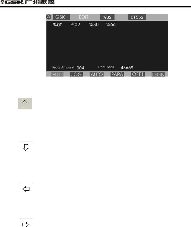
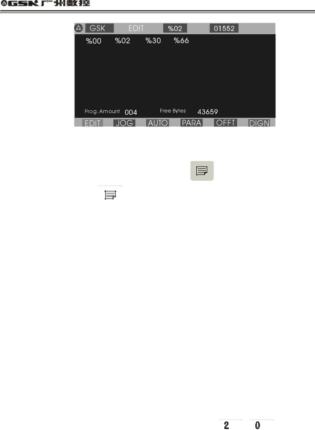
After pressing  to enter EDIT mode, the system displays program names of all part programs stored in the current program, the byte amount contained in current program and the available memory bytes of system. See Fig. 2:
15
GSK928TE Turning CNC System User Manual
Fig. 2 EDIT operating mode
Edit keys in EDIT mode
(1) |
|
|
|
|
|
|
|
cursor UP key |
|
|
|
|
|
|
|
||
|
|
|
|
|
|
|
||
|
|
|||||||
|
|
|
|
|
The cursor moves to the first character behind the block number of the upper block when the
key is pressed once.
The key being pressed down, the cursor sequentially moves up till the first block of block or the key is released.
(2)

 cursor DOWN key
The cursor moves to the first character behind the block number of the next down block
when the key is pressed once.
The key being pressed down, the cursor sequentially moves down till the last block number of block or the key is released.
(3)

 cursor LEFT key
The cursor moves left one character when the key is pressed once.
The key being pressed down, the cursor sequentially moves left till the first character of block or the key is released.
(4)

 cursor RIGHT key
The cursor moves right one character when the key is pressed.
The key being pressed down, the cursor sequentially moves right till the last character of block
or the key is released.
Note Cursor — prompt identifier to indicate the current editable character position. There are two states of CNC system.
A.The cursor is displayed to a horizontal line under a character in Insert mode.
B. The cursor is displayed to the pointed character in inverse and highlight. The two
cursors can be switched by .
.
16
GSK928TE Turning CNC System User Manual
5  DRY Run key
The cursor moves to the head of block or the head of first word of this block by pressing continuously.
6  STEP/JOG mode
The cursor moves to the behind of the last character of this block.
7 |
REWRITE key |
|
Switch INSERT/REWRITE mode once when the key is pressed once, and the cursor will |
|
change correspondingly. The cursor in Insert mode is a flashing horizontal line, but that in |
|
Rewrite is a character in flashing highlight. |
8  When the key is pressed once, the program number with 2-digit is input to create a new program, select or delete the existing program and all programs.
9 |
PAGE UP |
Search the program number and display the content of previous page. |
(10) |
PAGE DOWN Search the program number and display the content of next page. |
|
(11)


 Double functions key. Each key has two definitions. Pressing it once is the first definition value namely, U W I K D R. The same key is pressed again, the system will automatically rewrite the previous input value into the second definition value, namely / E P N L
  . If the same key is pressed continuously, the input value will be switched between the first definition value and the second one. ‘/’ is the
skip block character ‘  ’is the space character.
4.3.1Searching Directory of Part Program
In EDIT mode, the system displays the program name list of all part programs, all part program amount and the leftover bytes in the part program memory area of CNC system. In EDIT mode, the system displays the program name list of all part programs, all part program amount and the leftover bytes in the part program memory area of CNC system.
Press  in EDIT mode or press
 or
or  when editing programs as Fig. 3:
17
GSK928TE Turning CNC System User Manual
Fig. 3 Searching a part program catalog / creating, selecting and deleting part programs
Most %00 %99 program names are displayed in each screen. When part programs in memory
area are over 100, they are displayed by paging. Press |
to display the program number |
list of next page and press
 to display again the program number list of first page till the last page.
4.3.2Creating, Selecting, Deleting, Renaming and Copying a Part Program
The above-mentioned operations can be executed in the state of catalog search of part program or in the course of editing program content.
The system displays as Fig. 4 when is pressed in the state of catalogue search of part program.
4.3.2.1Creating a New Part Program
(1)Press  in the state of catalog search of part program.
(2)Input a new program number which does not exist in the program catalog list with 2-digit by keyboard. See Fig. 4.
(3)Press  .
.
(4)After part programs are created, the system will automatically enter EDIT mode.
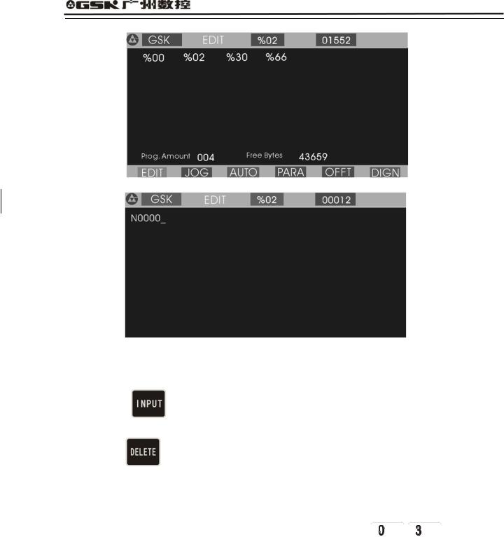
Example: Creating %20 program: Press  to input


 and press
 . So the program has been created to enter EDIT mode of %20 program. See Fig. 5:
18
GSK928TE Turning CNC System User Manual
Fig. 4 Inputting a program number
Fig. 5 Creating a new part program
4.3.2.2 Deleting a Part Program |
|
|
|
||
(1) |
Press |
in the state of catalog |
search of part |
program. |
|
(2) |
Input the required deleted program number by keyboard. |
|
|||
(3) |
Press |
and the system will display |
|
|
|
Confirm |
. |
|
|||
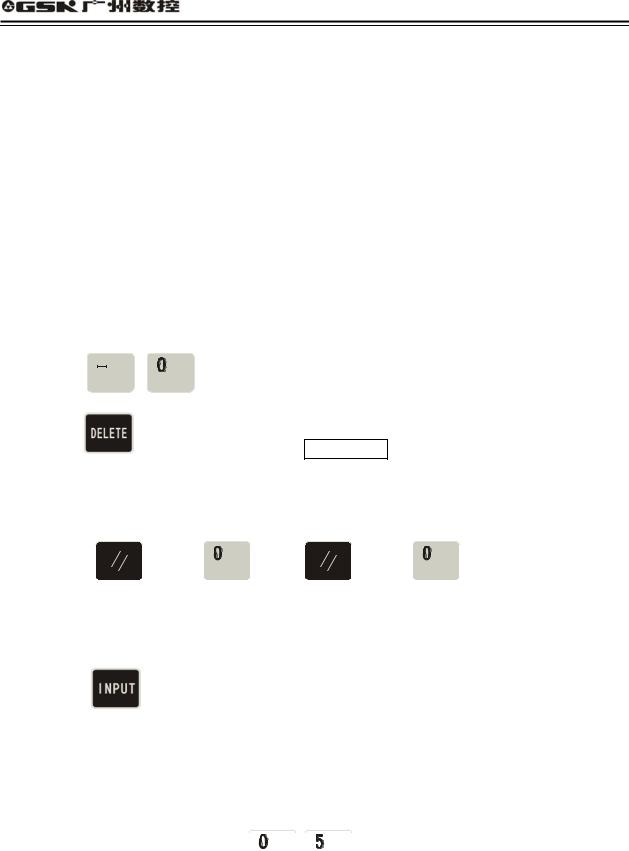
(4)Press to delete the part program which program number has been input; press any keys to cancel the deletion.
Example: Deleting %03 program: press and then orderly
 ,
,
 ,
, 
and  , so the program is deleted as Fig. 6:
19

GSK928TE Turning CNC System User Manual
Fig. 6 Deleting a part program
4.3.2.3Selecting a Part Program
(1)Press in the state of catalog search of part program.
(2)Input the required selected program number by keyboard.
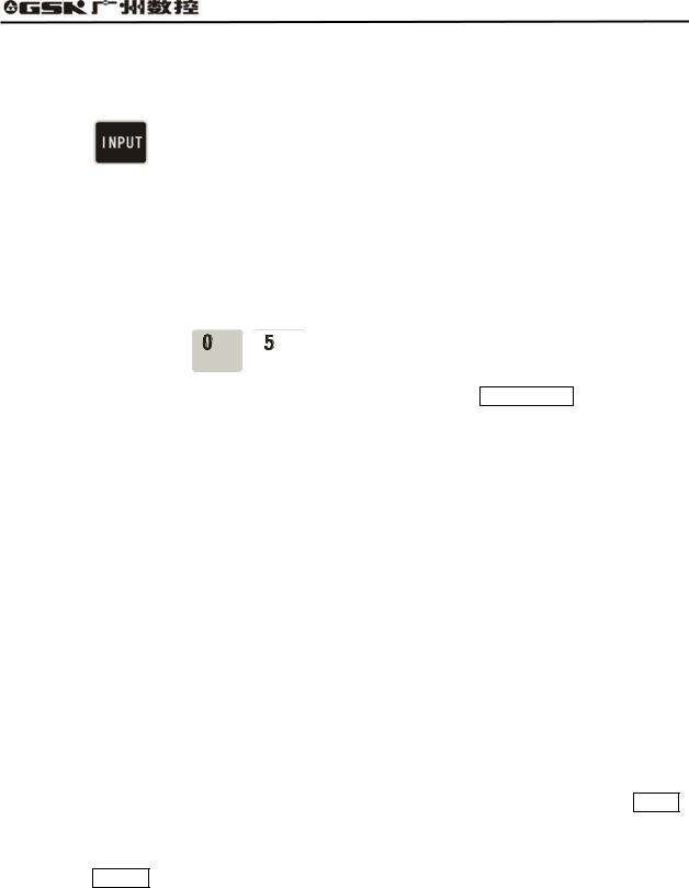
(3)Press  .
.
(4)The part program is selected completely and the system displays its content to enter EDIT mode.
Example: Selecting %01 part program.
Press to input


 and then press
 , so the selection is completed. See Fig. 7:
Fig. 7 Selecting a part program
Note 1 After the first power on, the system enters EDIT mode or there is no content in the memory area of part program, it will automatically create and select %00 program. The system will consider %00 as the current program after it be initialized.
Note 2: After the system has selected one program, the required one is changed only by selecting it. Even if the system powers off, the selected program number cannot be changed once it is selected.
20

GSK928TE Turning CNC System User Manual
4.3.2.4 Outputting a Part Program
Output part programs from CNC system internal memory to the external computer.
1. Connect the communication cable between CNC system and the computer when power off.
1.After CNC powers on, select EDIT mode.
2.Select the required part program according to Section Operation, 4.3.2.3 Select a part program (do not select it if the current program is to be sent).
3.Press 

 , and the system prompts Ready To Send .
4.Keep the computer in the state of waiting for the receiving See appendix: GSKR 232 communication program specification .
5. After the computer is ready, if |
is pressed, the system will prompt |
Sending … |
, and |
so the system sends the selected program to the computer.
6.After the sending has completed, the system prompts Finished , and any keys are pressed to return to EDIT mode.
7.Press to pause the sending.
4.3.2.5 Inputting a Part Program
Input the stored part program from the external PC to CNC system.
(1) Connect the communication cable between CNC system and the computer when power off.2 After CNC system powers on, select EDIT mode.
|
|
|
|
|
|
|
|
|
|
|
|
|
|
|
3 Press |
|
|
|
|
|
and the system prompts |
Ready To receive |
. |
|
|
|
|||
|
|
|
|
|
||||||||||
|
|
|
||||||||||||
|
|
|
|
|
|
|
|
|
|
|
|
|
|
|
(4) |
Keep the computer in the state of |
output. (See Appendix GSKTR communication |
||||||||||||
|
program specification ). |
|
|
|
|
|
|
|
||||||
(5) |
After the system is ready, if |
|
|
|
|
|
||||||||
is pressed, the system will prompt |
Receiving … |
, |
||||||||||||
|
and so the system sends the selected program to the CNC system. |
|||||||||||||
|
|
|
||||||||||||
(6) |
After the receiving is completed ,the system prompts |
Finished |
and returns to EDIT |
|||||||||||
|
mode if any keys are pressed. The system displays the input program name in the catalog |
|||||||||||||
|
list of part program. |
|
|
|
|
|
|
|
||||||
(7) |
Press |
to interrupt the receiving. |
||||||||||||
Note 1: In the course of inputting part program, CNC system considers the character string “% XX” contained in the first block of the sent program from the computer as the program
21
GSK928TE Turning CNC System User Manual
name to save. If the sent program name is the same as one in CNC system, the system cannot display the program name content of the sent program name, and will display it if the old one is deleted.
Note 2: Send/receive part programs between 2 GSK928TE CNC systems according to the above–mentioned methods. 2 CNC systems separately operate according to part program input/output ways.
Note 3: It must have the block number of part program when the part program is sent from PC to CNC system, otherwise there is a mistake.
4.3.2.6 Deleting All Part Programs
Delete all programs once in the program memory area of CNC system.
Press in the state of catalog search of part program.
Input |
, |
by keyboard. |
Press |
and the system prompts Confirm |
|
Press to delete all part programs. Press other keys, and the system does not execute the deletion and returns to EDIT mode.
Note: Press 
 and then
 , release
 and then
 to delete all part program.
4.3.2.7 Renaming a Part Program
Rewrite the current program name to another one.
Press |
, and the system displays |
% |
. |
Input the |
program name which does |
not exist in the program name list, and press |
|
 to rewrite the current program name to the input program name.
Example: Rename the current program name %00 to % 05.
Press  to input


 , and press
  , so the renaming is completed.
22
|
GSK928TE Turning CNC System User Manual |
||
|
|
|
|
4.3.2.8 Copying a Part Program |
|||
Copy the content of current program to another new one and consider it as the current one. |
|||
|
|
|
|
Press |
, and the system displays |
% |
. |
Input a program name which does not exist in the program name list, and press to copy all contents of current program to the program whose number is input.
The new program name becomes the current one.
Example: Copy program of current program name % 00 to that of %05.
Press to input


 , and press
 , so the copy is completed.
Note: If the input program name exists, the system will prompt File Existed . At the moment, press any keys to input again the program name which does not exist in the program area,
and then press , So the copy is completed.
4.3.3 Inputting/Editing Content of Part Program
CNC machining is defined that the system automatically completes the machining of workpiece according to the part program sequence input by user. Each program is composed of many blocks and each block consists of a block number, codes and data. Start the machine and gain the standard workpiece after inputting the part program content according to the technology flow.
EDIT mode of CNC system uses the full-screen and part programs are employed with the file management mode.
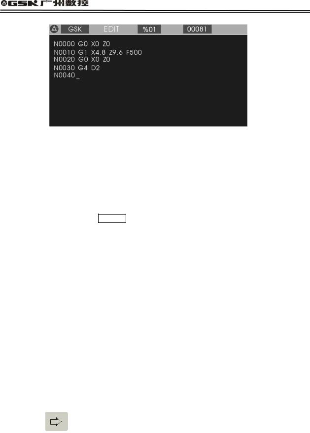
4.3.3.1 Automatically Creating a Block Number
Each part program contains many blocks and each block begins with the block number“ N**** ”; After a new program is created, the system will automatically generate the first block
number“ N0000 ”; After one block is input and  is pressed, the system will generate the next block number. In the course of input, the increment of block number is defined by P23. When a block is inserted, the system will automatically consider the 1/4 integer value of P23 as the increment to generate the block number. When M98, M97, M91, M92, M93, M94 and others codes related with the block number are executed, there are no repetitive block numbers in the program, otherwise the system will alarm. If the above codes are not executed, the block number can be repeated.
See Fig. 8 for a program generation and inserting a block number in a block (P23 value is 10).
23
GSK928TE Turning CNC System User Manual
Fig. 8 automatically creating block number and inputting program content
4.3.3.2 Inputting Content of Program
EDIT mode of the CNC system is employed with the full screen. Inputting content of program is executed in EDIT mode.
(1) Create a new program according to the creating method of new part program.
(2) After the block number N0000 is displayed, input the content of one block by keyboard.
(3)Input completely one block and then press .
.
(4)The system will generate the sequence number of next block and the content of program should be input continuously.
(5)Input completely the last block and press to end the input of content of program.
(6)The cursor rapidly moves in the block.
Press once, and the cursor will point to the head of word; press it again and the cursor points to the head of block, and the above steps are executed circularly.
Press once, the cursor points to the end of block.
(7) Insert a block in the first block.
Move the cursor to the head of the first block and then press .
.
Note: There are 255 characters at most in one block. When the characters exceed the screen,
pressing 

 displays one character left.
4.3.3.3 Inserting a Block
Insert one or more blocks between two blocks.
24
GSK928TE Turning CNC System User Manual
(1)Press 


 to move the cursor to the first one of two blocks.
(2)Press 

 to move the cursor to the behind of last character, or press
  to move directly the cursor to the behind of last character.
(3)Press , and the system will generate a new block number between two blocks (the increment of sequence number is 1/4 integral value of P23, and if there is not enough, the block number of the next block is rewritten.) and blank one block.
(4)Input the content of required block.
(5)After the content is input,  is pressed to insert blocks. When only one block is inserted, the operation is not executed.
(6)The inserting is completed.
(7)If the block is inserted before the first block,  is pressed to move the cursor to the under “N” of the first block, and the system will generate a new block number before the first block after
 is pressed.
Note After one block is inserted behind the last block and is pressed, the system will automatically generate the next block number.
Example Insert a new block |
M3 |
between |
N0020 |
and |
|
|
N0030 |
in |
Fig. 8 as follows: |
|||||||||||||||||
(1) Press |
|
|
|
|
|
|
|
|
|
|
|
|
|
|
|
|
to move the cursor to |
|
, and press |
to move the |
||||||
|
|
|
|
|
|
|
|
|
|
|
|
|
||||||||||||||
|
|
|
|
|
|
|
|
|
|
|
|
|
|
|
|
|
||||||||||
|
|
|
|
|
|
|
|
|
|
|
|
|
|
|
|
|
|
|
||||||||
|
|
|
|
|
|
|
|
|
|
|
|
|
|
|
|
|
||||||||||
|
|
|
|
|
|
|
|
|
|
|
|
|
|
|
|
|
||||||||||
|
|
|
|
|
|
|
|
|
|
|
|
|
|
|
|
N0020 |
||||||||||
|
|
|
|
|
|
|
|
|
|
|
|
|
|
|
|
|||||||||||
|
|
|
|
|||||||||||||||||||||||
|
|
|
|
|
|
|
|
|
|
|
|
|
||||||||||||||
cursor to the behind of Z0.0. |
|
|
|
|||||||||||||||||||||||
(2) Press  and the system will automatically generate one block number and blank a block to display N0022 as Fig. 9. The cursor points to the first input character of the new block.
(3)Input 


 .
.
(4)The inserting is completed as Fig. 10.
25

GSK928TE Turning CNC System User Manual
Fig 9. Generating a new block number after is pressed
Fig. 10 Input and end the insertion
4.3.3.4 Deleting a Block
Delete all content in one block (including block number).
(1) Press |
|
|
|
|
|
|
|
|
|
|
|
|
|
|
|
|
|
|
|
to move the cursor to the required block. |
|
|
|
|
|
|
|
|
|
|
|
|
|
|
|
|
|
|
|
|
|
|
|||
|
|
|
|
|
|
|
|
|
|
|
|
|
|
|
|
|
|
|
|
|||
|
|
|
|
|
|
|
|
|
|
|
|
|
|
|
|
|
|
|
|
|||
|
|
|
|
|
|
|
|
|
|
|
||||||||||||
|
|
|
|
|
||||||||||||||||||
|
|
|
|
|
|
|
|
|
|
|||||||||||||
|
|
|
|
|
|
|
|
|
|
|||||||||||||
|
|
|
|
|
|
|
|
|||||||||||||||
(2) Press |
|
|
|
|
|
|
|
|
|
|
|
|||||||||||
|
|
|
|
|
|
|
|
|
|
|
|
|
|
|
|
|
|
|
|
|
|
|
|
|
|
|
|
|
|
|
|
|
|
||||||||||||
|
|
|
|
|
|
|
|
to move the cursor to the under of the address |
N |
of required block. |
||||||||||||
|
|
|
||||||||||||||||||||
|
|
|
|
|
||||||||||||||||||
(3)Press .
.
(4)Delete all content of the selected blocks.
4.3.3.5Inserting a Word in a Block
(1)Ensure the current input operation is in Insert mode, i.e. the cursor displays to the under of block. If  is not pressed, switch Input to Insert mode.
(2)Press 

 or
or

 to move the cursor to the address character behind the required
26
 Loading...