


GSK DA98B AC Servo Drive Unit
User Manual

 The operating manual describes all matters concerning the operation of the system in detail as much as possible. However, it is impractical to give particular descriptions of all unnecessary and/or unavailable works on the system due to the length limit of the manual, specific operations of the product and other causes. Therefore, the matters not specified herein may be considered impractical or unavailable.
 This operating manual is the property of GSK CNC Equipment Co., Ltd. All rights reserved. It is against the law for any organization or single to publish or reprint this manual without the express written permission of GSK and the latter reserves the right to ascertain their legal liability.
Company Profile
GSK CNC EQUIPMENT CO., LTD.(GSK) , CNC Industry Base of South China, is responsible for the National High Technology Research and Development Program of China (863 Program): Moderate CNC Industrialization Key Technology. For ten years, we are exclusively engaged in research, Development, manufacture, sale, training and popularization of Machine Tool CNC system, Servo Motor and driver, and other mechanical products. Today, GSK has already expressed into a large-scale new high-tech enterprise that deals with research, teaching, working and trading. Our products support more than 60 domestic manufacturers of machine tools with after-sales service network through the country. With a yield in the lead in China for four years in succession, GSK series products are in great demand in the domestic demand and have a ready sale in Southeast Asia at high performance-to-price ratio.
Chinese version of all technical documents in Chinese and English languages is regarded as final.

Forward
Foreword
The manual describes functions and operation methods of DA98B AC servo Drive Unit to ensure that you can comprehensively understand the servo unit to flexibly and conveniently use it. Else, it also provides the knowledge and notes how to operate the unit.
zAll specifications and designs are subject to change without notice.
zWe do not assume any responsibilities for the change of the product by users, therefore the warranty sheet will be void for the change.
zChinese version of all technical documents in Chinese and English languages is regarded as final.
Thank you for using DA98B AC Servo Drive Unit and User Manual. Welcome you to feedback your suggestions about our product and User Manual by the telephone or fax, Email which has been addressed on the back cover of this manual, or feedback to our headquarter by local outlet.
GSK CNC Enquipment Co., Ltd.
Warning
Please read carefully the following warning marks, if not avoided, could result in injury or in heavy damage to property.
■The following warnings with varying degrees of severity appear in the User Manual.
!Danger: Indicate an immenently hazardous situation which, if not
avoided, will result in death or serious injury.
!Caution: Indicate a potentially hazardous situation which, if not
avoided, may result in minor or moderate injury or in damage to property.
Indicate a potential situation which, if not avoided, may result in an undesirable result or state.
This symbol appears in the user Manaul whenever it is necessary to draw your attention to an important item of information.
■ The following symbols indicate some operations must not or must be performed.
Forbid performing some operation (absolutely must not perform some operation).
Perform some operation (must perform some operation).
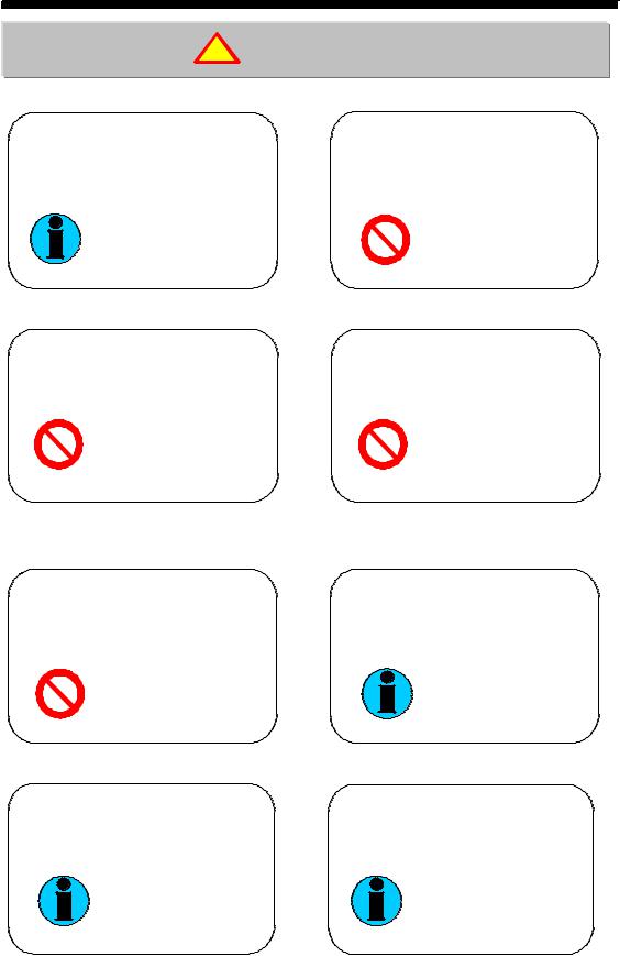
Warning
!Danger
The cable is not permitted to be put on the trenchant edge and excessive pressure, load, tension is not permitted to exert on it
Electric shock, fault, damage occurring if the indication not observed
Moving, wiring and checking can only be performed after the power is switched off for 10 minutes.
Electric shock occurring if the indication not observed
GSK CNC Enquipment Co., Ltd.
!Caution
When there is an alarm in the running, it must be eliminated before going on running.
Destructive result occurring if the indication not observed
Don't touch the motor, control device or the brake resistance for the heating in the running.
Scalding occurring if the indication not observed

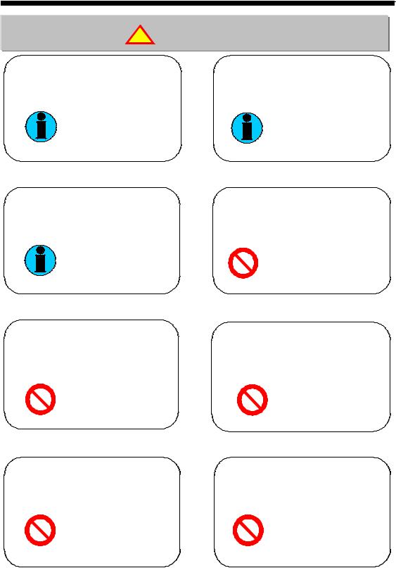
Warning
!Notes

GSK CNC Enquipment Co., Ltd.
|
|
|
Content |
|
|
Content |
|
Chapter 1 |
Overview ............................................................................................... |
1 |
|
1.1 |
Introduction ................................................................................................................... |
1 |
|
1.2 |
Check after delivery ...................................................................................................... |
2 |
|
1.3 |
Outline |
............................................................................................................................ |
4 |
Chapter 2 |
Installation ............................................................................................ |
5 |
|
2.1 |
Installing .......................................................................................................servo unit |
5 |
|
2.2 |
Installing ..............................................................................................................motor |
7 |
|
Chapter 3 .............................................System configuration and assembly |
9 |
||
3.1 |
Servo unit .................................................................................................specification |
9 |
|
3.2 |
Interior ...........................................................................diagram block of servo unit |
11 |
|
3.3 Wiring ............................................................................................................................ |
|
11 |
|
3.4 |
I/O Interface .........................................................................................fundamentals |
18 |
|
3.5 |
Standard ......................................................................................................conection |
23 |
|
3.5.1 Orientation .............................................................................................................control |
23 |
||
3.5.2 Speed .....................................................................................................................control |
25 |
||
Chapter 4 ........................................................................................... |
Parameter |
27 |
|
4.3 |
Model code ............................................................................parameters for motors |
33 |
|
Chapter 5 .....................................................................Display and operation |
35 |
||
5.1 |
Keys operation ............................................................................................................. |
35 |
|
5.3 |
Parameter .........................................................................................................setting |
39 |
|
Chapter 6 ............................................................................................... |
Trial run |
43 |
|
6.1 |
Check before .................................................................................................trial run |
43 |
|
6.2.1 Sequence .......................................................................of power on for servo unit |
44 |
||
6.2.2 JOG .......................................................................................................................running |
45 |
||
6.2.3 (Sr- .......................................................................................................................) trial run |
46 |
||
6.2.4 Speed ..............................................................................................................control run |
46 |
||
6.2.5 Orientation ......................................................................................................control run |
49 |
||
6.3 Application ...............................................................................of hold release signal |
52 |
||
6.4 |
Parameter ......................adjustment for machining characteristics improvement |
54 |
|
Chapter 7 ...................................................................Funciton for protection |
57 |
||
Chapter 8 ........................................................................ |
Isolated transformer |
64 |
|
Chapter 9 ........................................................................................ |
Order guide |
69 |
|
9.1 |
Capacity ........................................................................................................selection |
69 |
|
9.2 |
Electronic ....................................................................................................gear ratio |
72 |
|
9.3 |
Stop characteristic ....................................................................................................... |
72 |
|
9.4 |
Servo and ..........................................................orientation controllor computation |
73 |
|
1

GSK CNC Enquipment Co., Ltd.
2

Chapter 1 Overview
Chapter 1 Overview
1.1 Introduction
DA98B AC Servo Drive Uit is the second generation of fully digital AC Servo system of our company which is employed with the new type exclusive chip DSP for motor control, large-scale complex programmable logic device (CPLD) and IPM with big power, which has a good integration, compact, perfect protection and highly reliability. It is characterized with the f orientation control, interior speed control, analog speed control etc. and is widely applied in the automation production line, packing machinery and printing machinery and other automatic field.
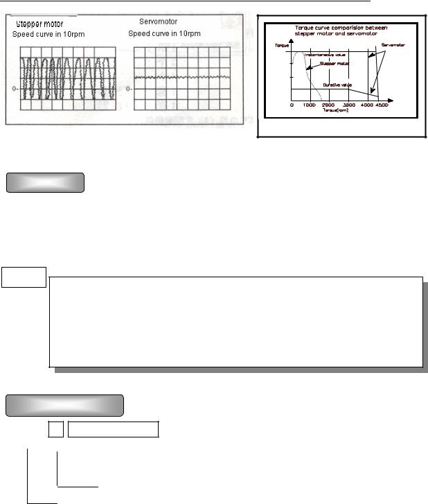
Compared to stepper system,
DA98B AC Servo Driver Unit has advantages as follows:
zAvoiding out-of-step
Servomotor is equipped with encoder, its orientation signal feedbacks to servo driver with open loop orientation controller to compose a semi-closed loop control system.
Open loop control
Stepper motor
Controller 


z Speed ratio, constant torque
Positioning instruction
The timing ratio is 1 5000 with stable torque from low speed to high speed.
zHigh speed, high precision
|
Feedback control |
Servo motor |
|
|
|
Max. speed can be 3000rpm, and the |
|
|
speed fluctuation rate is less than 2 . |
|
|
Note There is different rated speed |
|
|
for different motors. |
Controller |
|
|
Feedback |
|
|
|
|
z Simple and flexible control |
Positioning instruction |
|
Parameters can be modified to set properly operating mode, running performance of servo system to meet different requirements.
1
GSK CNC Equipment Co., Ltd.
1.2 Check after delivery
Item
1)Whether the packing is good and the goods is damaged.
2)Whether the servo unit, servo motor is the ordered one by checking the nameplates of the goods.
3 Whether the accessories are complete by checking the packing list.
z Do not install servo unit which is damaged or lacks of components.
zServo driver must be matched with servomotor which performance matches the former.
zPlease contact with our suppliers or our company if there are any questions after receiving goods.
Model significance
DA98B-04-110SJT-M060D

 Matched servo motor type
Output power (see table1-a)
Series code
Mark |
Rated output |
Mark |
Rated output |
Mark |
Rated output |
|
|
|
|
|
|
04 |
0.4 kW |
12 |
1.2 kW |
18 |
1.8 kW |
|
|
|
|
|
|
06 |
0.6 kW |
14 |
1.4 kW |
20 |
2.0 kW |
|
|
|
|
|
|
08 |
0.8 kW |
15 |
1.5 kW |
23 |
2.3 kW |
|
|
|
|
|
|
10 |
1.0 kW |
17 |
1.7 kW |
26 |
2.6 kW |
|
|
|
|
|
|
Table 1 a
2
Chapter 1 Overview
1 Standard accessories for DA98B servo unit: |
|
|
|
|
User Manual |
1 |
|
|
Installation bracket |
2 |
|
|
M4×8 contersink bolt |
4 |
|
|
CN1 socket DB44 female |
1 set |
note 1 |
CN2 plug DB25 male |
1 set |
note 2 |
|
Accessory list
1 Signal cable (3m) can be provided when it is matched with our servo unit.
2 Feedback cable (3m) available should be used when our servo motor is provided.
2 Standard accessories of servo motor are provided according to user manual of servo motor.
3
GSK CNC Equipment Co., Ltd.
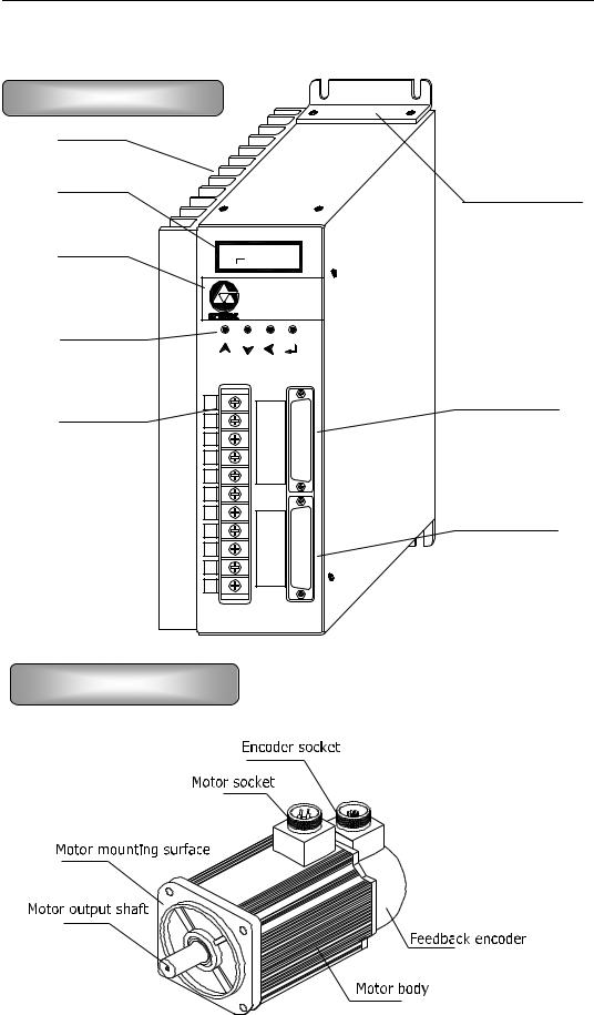
1.3 Outline
Outline of servo unit
Fig. 1.1 Outline of servo unit
Outline of servo motor
Fig. 1.2 Outline of servo motor
4

Chapter 2 Installation
Chapter 2 Installation
Servo unit and servo motor should be correctly installed to avoid the mistaken operation, to protect the machine from being broken or damaged.
2.1 Installing servo unit
Installation environment
Be careful for the protection against rain and sunlight while the servo unit is being installed.
Servo unit must be installed in the electric cabinet to prevent dust, corrosive gas, liquid, conductors and inflammable substances from entering it.
Servo unit should be fixed in the well ventilative, dampproof and dustproof environment.
Fireproof material should be used in the installation with no permission to fix it on or near the inflammable object.
Run the servo unit below the temperature of 45 for reliable long term usage.
Environmental requirements
|
|
|
|
|
Item |
DA98B servo unit |
|
|
|
|
|
|
Operating temperature |
0 55 no frost |
|
|
≤90%RH no dewing |
|
|
|
|
|
|
|
|
|
|
|
Storage/delivery temperature |
-40 80 |
|
|
and humidity |
≤90%RH no dewing |
|
|
|
|
|
|
Atmosphere environment |
There should be no corrosive gas flammable gas, oil fog |
|
|
or dust etc. in the control cabinet. |
|
|
|
|
|
|
|
|
|
|
|
Altitude |
Altitude: below 1,000m |
|
|
|
|
|
|
Vibration |
≤ 0.5G 4.9m/s2 10-60Hz |
|
|
Atmospheric pressure |
86kPa 106kPa |
|
|
|
|
|
|
Guard level |
IP43 |
|
|
|
|
|
|
|
|
|
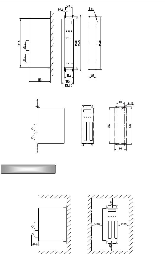
Installation method
The driver is employed with bottom board or panel installation mode in the upright direction of installation plane.
Fig. 2.1 is sketch map for bottom board installation and Fig. 2.2 for panel installation. (Unit below: mm)
5
GSK CNC Equipment Co., Ltd.
Fig 2.1 Bottom board installation pattern
Fig 2.2 Panel installation pattern
Installation interval
Fig. 2.3 is installation interval for one servo unit and Fig. 2.4 is for servo units. The actual interval for installation should be larger as possible as to get a good heat radiation.
Fig. 2.3 Installation interval for a single servo unit
6

Chapter 2 Installation
>100mm |
>25mm |
>25mm |
>100mm |
|
|
||||
driver Servo |
|
driver Servo |
|
driver Servo |
>100mm |
|
|
|
|
Ventilation |
direction |
Ventilation |
direction |
|
Fig. 2.4 Installation interval for servo units
Heat radiation
There should be convective air to the radiator of the servo unit in electric cabinet to inhibit its environmental temperature from continuously rising.
2.2 Installing motor
Installation environment
Be careful for the protection against rain and sunlight.
The motor must be installed in the electric cabinet to prevent dust, corrosive gas, liquid, conductors and inflammable substances from entering it.
The motor should be fixed in the well ventilative, dampproof and dustproof environment.
■ The motor should be fixed in a place that is convenient for the maintenance, check and cleaning of the motor.
7
GSK CNC Equipment Co., Ltd.
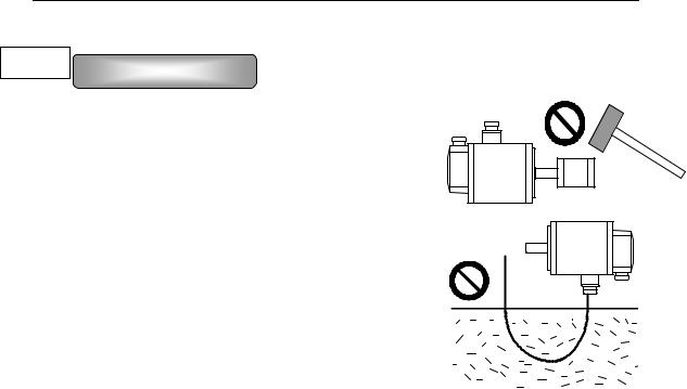
Installation notes
■ Do not hammer the motor or its shaft to protect the encoder from being damaged when removing or assembling belt wheel. Helically pressing or drawing tools should be used for removing and assembling.
■Servo motor cannot support heavy axial, radial load. It should be employed with flexible shaft coupling for load.
■Anti-loose washer should be used to fix the motor against loosing.
■Oil and water should be protected from the motor for
that the oil or water from the cable which has been dipped in the oil or water can be sticked to the motor, so such possibility should be avoided.
8
Chapter 3 System configuration and assembly
Chapter 3 System configuration and assembly
3.1 Servo unit specification
|
|
|
|
Table 3 1 Servo unit specification |
|
|
|||||
|
|
|
|
|
1.0 1.5 |
|
|
||||
Output power (kW) |
0.4 0.8 |
|
|
1.7 2.6 |
|||||||
|
|
|
|
|
|
|
|
|
|
|
|
Motor |
|
rated torque |
|
2 4 |
|
4 10 |
|
6 15 |
|||
N·m |
|
|
|
||||||||
|
|
|
|
|
|
|
|||||
|
|
|
|
|
|
|
|
|
|
||
Input power supply |
Single |
phase |
or |
three-phase AC220V |
|||||||
three-phase AC220V |
|
-15 +10% 50/60Hz |
|
|
|||||||
|
|
|
|
-15 +10% 50/60Hz |
|
|
|
||||
|
|
|
|
|
|
|
|
||||
|
|
|
|
|
|
|
|
|
|||
Environment |
|
Temperature |
Working 0 55 Storage -20 80 |
|
|
||||||
|
|
|
|
|
|
||||||
|
Humidity |
Less than 90% no dewing |
|
|
|||||||
|
|
|
|
||||||||
|
Vibration |
Less than 0.5G 4.9m/s2 ,10 60 Hz(non-continuous running) |
|||||||||
|
|
|
|
|
|
|
|
||||
Control method |
Orientation control |
External speed control |
Internal speed |
||||||||
control Trial speed run JOG speed Encoder zero-adjusting |
|||||||||||
|
|
|
|
||||||||
|
|
|
|
|
|
|
|
||||
Energy brake |
Built-in |
|
|
|
|
|
|
||||
|
|
|
|
|
|
|
|
|
|||
|
|
|
Speed frequency response: 200Hz or more |
|
|
||||||
characteristics |
|
|
|
|
|||||||
Control |
|
Speed fluctuation rate: ±0.03 load 0 100% ±0.02 power supply -15 |
|||||||||
|
+10% numerical value corresponding to rated speed |
|
|
||||||||
|
|
|
|
|
|
|
|
||||
|
Timing ratio: 1:5000 |
|
|
|
|
|
|
||||
|
|
|
|
|
|
|
|
|
|||
|
|
Pulse frequency: ≤500kHz |
|
|
|
|
|||||
|
|
|
|
|
|
|
|||||
|
|
|
|
|
|
||||||
|
|
|
|
Servo on Alarm cancellation Disable in positive direction |
|||||||
Control input |
Disable |
in negative |
direction Zero-speed |
clamping Error |
|||||||
counter reset/speed choice11 Disable instruction pulse/speed |
|||||||||||
|
|
|
|
||||||||
|
|
|
|
choice 2 CCW torque limit CW torque limit Universal I/O port |
|||||||
|
|
|
|
|
|
||||||
|
|
|
|
Servo ready output Servo alarm output Orienting completing |
|||||||
Control output |
output/speed in-orientation output Hold release Zero speed |
||||||||||
|
|
|
|
output Universal output Pulse feedback output |
|||||||
|
|
|
|
||||||||
Orientation control |
Input mode |
|
Pulse+ direction CCU pulse /CW pulse A/B |
||||||||
|
|
|
|
|
|
orthogonal phases pulse |
|
|
|||
|
|
|
|
|
|
|
|||||
|
|
|
|
Electronic |
|
Ratio numerator:1 32767 Ratio denominator: 1 |
|||||
|
|
|
|
gear ratio |
|
32767 |
|
|
|
|
|
|
|
|
|
|
|
|
|
|
|
|
|
9

GSK CNC Equipment Co., Ltd.
|
Encoder |
2500 pulse/rev |
(resolution:10000) incremental |
||
|
Feedback |
encoder |
|
|
|
|
|
|
|
||
Speed control |
4 kinds of internal speed instructions and (+10 -10) external analog |
||||
voltage instructions |
|
|
|||
|
|
|
|||
|
|
|
|||
|
Speed, current orientation, instruction pulse accumulation, |
||||
Monitor function |
Orientation deviation, motor torque, motor current, linear |
||||
speed, rotor absolute orientation, instruction pulse frequency, |
|||||
|
|||||
|
running state, input/output terminal signal and so on |
||||
|
|
|
|||
|
Overspeed, overvoltage/under-voltage of main power supply, |
||||
Protection function |
overcurrent, overload, brake abnormity, encoder abnormity, control |
||||
|
power supply abnormity, orientation oversize |
||||
|
|
|
|
||
Display, operation |
6-bit LED digital tube, 4 buttons |
|
|
||
|
|
|
|
||
Load inertia |
Less than quintuple of motor inertia |
|
|
||
|
|
|
|
||
|
Thin radiating fin |
|
Thick radiating fin |
||
|
|
|
|
|
|
Weight |
2.67Kg |
|
|
3.48Kg |
|
|
|
|
|
||
Dimension |
244×163×92mm |
|
244×163×112mm |
||
|
|
|
|
|
|
10

Chapter 3 System configuration and assembly
3.2 Interior diagram block of servo unit
Fig. 3.1 Interior diagram block for DA98B servo unit
Control board diagram block inside the broken line and power supply board diagram block outside the broken line above.
3.3 Wiring
There are several control modes for DA98B: orientation control mode, speed control mode etc. Personnel who take up the wiring and checking should be qualified for
11
GSK CNC Equipment Co., Ltd.
the work, they must do wiring as the terminal voltage and poles by the manual for prevention of the device damage or the injury to personnel.
Main circuit wiring
|
|
|
|
|
|
|
|
|
|
|
|
|
|
|
|
|
|
|
|
|
|
|
|
|
|
|
|
|
|
|
|
|
|
|
|
|
|
|
|
|
|
|
|
|
|
|
|
|
|
|
|
|
|
|
|
|
|
|
|
|
|
|
|
|
|
|
|
|
|
|
|
|
|
|
|
|
|
|
|
|
|
|
|
|
|
|
|
|
|
|
|
|
|
|
|
|
|
|
|
|
|
|
|
|
|
|
|
|
|
|
|
|
|
|
|
|
|
|
|
|
|
|
|
|
|
|
|
|
|
|
|
|
|
|
|
|
|
|
|
|
|
|
|
|
|
|
|
|
|
|
|
|
|
|
|
|
|
|
|
|
|
|
|
|
|
|
|
|
|
|
|
|
|
|
|
|
|
|
|
|
|
|
|
|
|
|
|
|
|
|
|
|
|
|
|
|
|
|
|
|
|
|
|
|
|
|
|
|
|
|
|
|
|
|
|
|
|
|
|
|
|
|
|
|
|
|
|
|
|
|
|
|
|
|
|
|
|
|
|
|
|
|
|
|
|
|
|
|
|
|
|
|
|
|
|
|
|
|
|
|
|
|
|
|
|
|
|
|
|
|
|
|
|
|
|
|
|
|
|
|
|
|
|
|
|
|
|
|
|
|
|
|
|
|
|
|
|
|
|
|
|
|
|
|
|
|
|
|
|
|
|
|
|
|
|
|
|
|
|
|
|
|
|
|
|
|
|
|
|
|
|
|
|
|
|
|
|
|
|
|
|
|
|
|
|
|
|
|
|
|
|
|
|
|
|
|
|
|
|
|
|
|
|
|
|
|
|
|
|
|
|
|
|
|
|
|
|
|
|
|
|
|
|
|
|
|
|
|
|
|
|
|
|
|
|
|
|
|
|
|
|
|
|
|
|
|
|
|
|
|
|
|
|
|
|
|
|
|
|
|
|
|
|
|
|
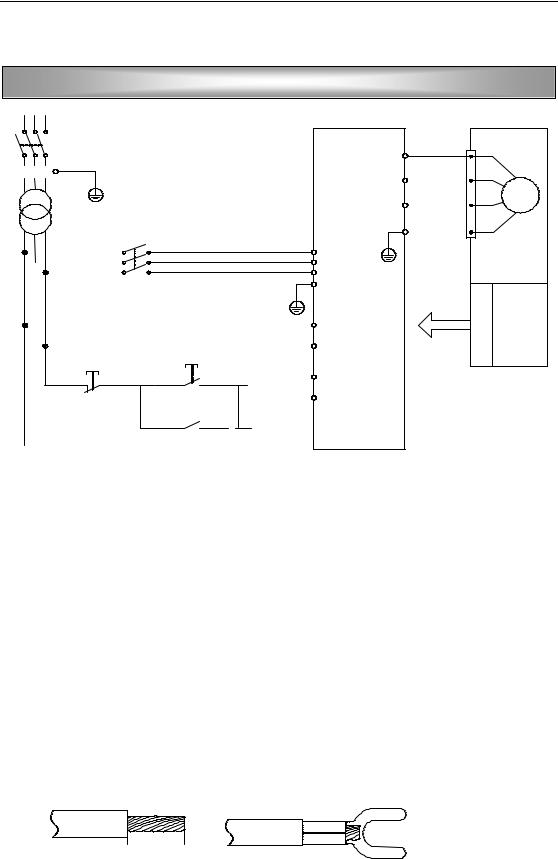
Fig.3.2 |
Typical wiring for the main circuit |
|||||||||||||
|
|
|
|
|
|
MCC Breaker |
|
|
|
|
|
|
|
FIL Disturbance filter |
||||||
|
|
|
|
|
|
TB Isolated transformer |
|
|
|
|
KM1 AC contactor |
|||||||||
|
|
|
|
|
|
R/C Surge inhibitor |
|
|
|
|
P, D Reserve |
|||||||||
■The breaker should be selected B type short circuit device, the drop-away current is more1.3 times than servo rated input one, otherwise is less than 1.05 times than the servo rated input current.
■Single phase power supply AC220V(+10% 15 ) can be employed when the precision is comparative low and the power is less than 0.8KW for servo unit, and its the wiring is as fig.3.2
■While connecting the terminals, peel the insulative surface of the wire and twist the naked copper wires, compress the wiring by the pre-insulation cold pressing terminals to fasten the connection.
 6 8mm
6 8mm 
Table 3 2 Wire sections for main circuit Unit: mm2
12

Chapter 3 System configuration and assembly
|
|
|
|
|
|
|
|
|
|
|
|
|
|
Output |
R |
S |
T |
PE |
U |
|
V |
|
W |
r |
t |
|
power |
|
|
|
|
|
|
|
|
|
|
|
|
|
Input terminals |
|
|
Output |
|
Input |
|||||
|
Type |
Protection |
|
|
terminals of |
|||||||
|
of the main |
earthing |
terminals of |
the |
control |
|||||||
|
|
power supply |
|
power |
|
|||||||
|
|
|
|
|
power |
|||||||
|
|
|
|
|
|
|
|
|
|
|
||
|
0.4 0.8 kW |
1.5 |
1.5 |
1.5 |
≥2.0 |
1.5 |
|
1.5 |
|
1.5 |
1.0 |
1.0 |
|
|
|
|
|
|
|
|
|
|
|
|
|
|
1.0 1.5 kW |
2.0 |
2.0 |
2.0 |
≥2.0 |
2.0 |
|
2.0 |
|
2.0 |
1.0 |
1.0 |
|
|
|
|
|
|
|
|
|
|
|
|
|
|
1.7 2.6 kW |
2.5 |
2.5 |
2.5 |
≥2.5 |
2.5 |
|
2.5 |
|
2.5 |
1.0 |
1.0 |
|
|
|
|
|
|
|
|
|
|
|
|
|
|
|
|
|
|
|
|
|
|
|
|
|
|
! Caution to main circuit wiring:
Wires from power supply must not be directly connected with the U, V, W terminals.
U, V, W wires should connect with motor terminals correspondingly. Operation of reverse rotation for motor by exchanging the wires of three-phase terminals is not allowed.
Due to the high frequency switch current in the motor, the leaking current is relatively larger, the motor grounding terminal must be connected with the servo unit grounding terminal PE and the grounding resistance should be less than 100Ω.
Do not touch the servo unit and motor in 5 minutes after the power supply is switched off because there is large electrolytic capacitance keeping high voltage inside the servo unit even if it is switched off.
Operator should keep a certain distance to the servo unit and motor after the power is switched on.
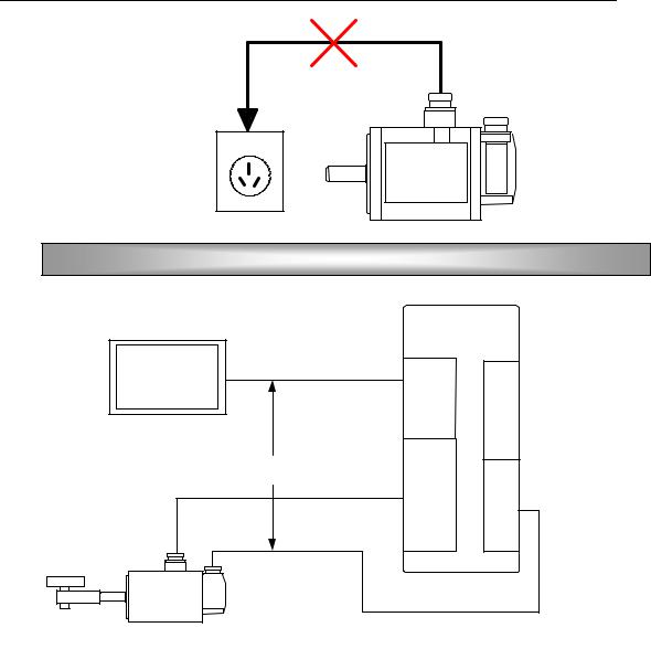
Servo motor must not be drived by the industrial power directly connecting to the U, V, W terminals of motor in the absence of servo unit, or the servo motor will be damaged.
13
GSK CNC Equipment Co., Ltd.
CN2 terminal wiring
The cable length between the servo unit and motor should be within 20 meters.
The distance between the feedback cable of encoder and main circuit cable should be over 30cm as well as the both cables should not use the same tube or be bound together.
Shielded cable with the size 0.15mm² 0.20mm²(AWG24-26) should be used for feedback signal cable, and the shielded tier should connect with FG terminal.The cables and wares should be well fixed as well as not be adjacent to servo unit radiator or motor for their protection of insulation against heating.
The wiring of CN2 in the following sketch map is done by accordance of GSK SJT series motor. If user uses motor from other manufacturers or self-made wires, the wiring below should be followed by. Leading wires of temperature controller connect to OH, OV terminals for motor with temperature controller.
14

Chapter 3 System configuration and assembly
V aca ncy
CN2 (DB25F)
Fig.3.3 Encoder wiring
CN1 terminal wiring
The cable length of the control signal should be within 3m.
The distance to the main circuit cable should be above 30cm as well as the both cables should not use the same tube or be bound together for protection against disturbance.
The external power supply should be provided by user.
There are different wirings for CN1 terminal in different control modes, see section 3.5 for details.
15
 Loading...