


 Loading...
GSK980MD MILLING CNC SYSTEM
User Manual

PREFACE
Warning
Before installation, programming and operation, read this manual and the machine builder manual carefully and perform the relevant operations strictly by the instructions in the manuals. Or else it may result in product and machine damage, workpiece scrap, even serious personal hurt.
NOTE
The functions, technical specifications such as precision, speed introduced in this manual are only suitable for this product and those machines fixed with this product. The actual function configurations and technical performance are depended on the machine builder’s design. And the CNC machine function configuration and technical specifications are defined by machine builder’s manual.
Though this system is employed with integrated operator panel, the functions of the keys on the panel are defined by PLC program (ladder). It should be noted that the keys functions are narrated for the standard PLC program in this manual.
For the panel key functions and significance, please refer to the machine builder’s manual.
The content of this manual is subject to change without further notice.

GSK980MD milling CNC system
CAUTIONS
■ Transportation and Storage
The product package box stacking should not exceed 6 layers.
Don’t crawl, stand or place heavy object on the product package box.
Don’t draw or move this product by the cables connected with it.
Don’t collide to or scratch panel and displayer.
The product package box should be prevent from moisture, insolation and drenching.
■ Check by opening box
Whether the product is the ordered one after opening the package. Whether the product is damaged during transiting.
Whether the parts are complete or damaged by ordering sheet.
If the product model doesn’t correspond to the ordered one, subsidiaries are lacking or damaged in transiting, please contact us in time.
■ Wiring
Wiring and check should be done by the qualified technicians.
This product must be securely grounded with a grounding resistance less than 4Ω, and the grounding wire can’t be replaced by a neutral wire (zero wire)
The wiring must be correct and secure to protect against product fault or unexpected result.
The surge diode connected with this product must be joint by the specified direction or this product may be damaged.
The power supply of this product must be cut off prior to pluging or opening the product cabinet.
■ Reparation
Cut off the power supply before reparation or component replacement.
If short-circuit or overloading occurs, check the fault first, then restart after the fault is eliminated. Don’t switch on or off power frequently, the interval should be at least 1 minute for the repowering after power off.

PART 1
PROGRAMMING
Programming 1 Part

Contents
CHAPTER 1 |
PROGRAMMING .................................................................................................. |
|
-1 |
|
1.1 |
GSK980MD Brief ............................................................................................................ |
|
-1 |
|
1.2 |
Execution of the Program ................................................................................................ |
|
-7 |
|
|
1.2.1 Order of the program execution............................................................................. |
-7 |
||
|
1.2.2 Execution order of command word within block................................................... |
-8 |
||
CHAPTER 2 |
MSTF COMMAND ................................................................................................ |
|
-1 |
|
2.1 |
M Command (Miscellaneous Function) .......................................................................... |
-1 |
||
|
2.1.1 EP (End of program) M02...................................................................................... |
|
-1 |
|
|
2.1.2 |
End - of - run M30 ..................................................................................................... |
|
-2 |
|
2.1.3 |
Subprogram call M98 ............................................................................................ |
|
-2 |
|
2.1.4 Return from subprogram M99 ............................................................................... |
-2 |
||
|
2.1.5 Macro program call M9000~M9999...................................................................... |
-3 |
||
|
2.1.6 M command defined by standard PLC ladder diagram ......................................... |
-4 |
||
|
2.1.7 |
Program stop M00 .................................................................................................. |
|
-4 |
|
2.1.8 Spindle CCW, CW, stop control M03, M04 and M05 ........................................... |
-4 |
||
|
2.1.9 Coolant control M08, M09 .................................................................................... |
|
-4 |
|
|
2.1.10 Lubricant control M32, M33................................................................................ |
-5 |
||
2.2 |
Spindle Function .............................................................................................................. |
|
-6 |
|
|
2.2.1 Spindle speed switching value control................................................................... |
-6 |
||
|
2.2.2 Spindle speed analog voltage control..................................................................... |
-6 |
||
|
2.2.3 |
Spindle override ..................................................................................................... |
|
-7 |
2.3 |
Tool Function ................................................................................................................... |
|
-8 |
|
2.4 |
Feeding Function.............................................................................................................. |
|
-8 |
|
|
2.4.1 Cutting feed (G94/G95, F command) .................................................................... |
-8 |
||
|
2.4.2 |
Manual feed ......................................................................................................... |
|
-10 |
|
2.4.3 |
MPG/ Step feed .................................................................................................... |
|
-10 |
|
2.4.4 Automatic acceleration or deceleration ............................................................... |
-10 |
||
CHAPTER 3 |
G COMMAND ........................................................................................................ |
|
-1 |
|
3.1 |
Brief |
................................................................................................................................. |
|
-1 |
|
3.1.1 Modal, non-modal and initial................................................................................. |
|
-3 |
|
|
3.1.2 ................................................................................................................ |
Examples |
|
-3 |
|
3.1.3 ................................................................................................... |
Related definition |
|
-3 |
|
3.1.4 .................................................................................................. |
Address definition |
|
-4 |
3.2 |
Rapid ..................................................................................................Positioning G00 |
|
-6 |
|
3.3 |
Linear ..................................................................................................Interpolation G01 |
|
-7 |
|
3.4 |
Arc and ..........................................................................Helical Interpolation G02, G03 |
-8 |
||
3.5 |
Dwell ......................................................................................................................G04 |
|
-12 |
|
3.6 |
Plane ..............................................................Selection Command G17, G18 and G19 |
-13 |
||
3.7 |
Conversion .........................................................of Inch and Metric |
G20 and G21 |
-14 |
|
3.8 |
Reference ..........................................................................................Point Return G28 |
|
-15 |
|
3.9 |
Return .................................................................................From Reference point G29 |
|
-16 |
|
3.10 The 2nd, .........................................................3rd and 4th Reference Point Return G30 |
-17 |
|||
3.11 |
Skip .......................................................................................................Function G31 |
|
-19 |
|
3.12 Tool ....................................................Radius Compensation C (G40, G41 and G42) |
-21 |
|||
3.13 Tool ..............................................................Length Compensation (G43, G44, G49) |
-23 |
|||
Programming 1 Part
I

Programming 1 Part
|
|
GSK980MD Milling CNC System |
|
|
|
|
|
3.14 |
Workpiece Coordinate system G54~G59 ............................................................... |
-26 |
|
3.15 |
Compound Cycle Command........................................................................................ |
-28 |
|
|
3.15.1 Brief for canned cycle........................................................................................... |
-28 |
|
|
3.15.2 Description for canned cycle ................................................................................ |
-32 |
|
|
3.15.3 Cautions for canned cycle..................................................................................... |
-53 |
|
|
3.15.4 Examples for modal data specified in canned cycle............................................. |
-55 |
|
|
3.15.5 Examples for canned cycle and tool length compensation................................... |
-56 |
|
3.16 Absolute and Incremental Commands G90 and G91 .................................................. |
-58 |
||
3.17 Workpiece Coordinate System Setting G92 ................................................................ |
-58 |
||
3.18 Feed per min. G94, Feed per rev. G95......................................................................... |
-59 |
||
3.19 |
G98 G99.................................................................................................................... |
-60 |
|
3.20 |
Chamfering Function ................................................................................................... |
-60 |
|
|
3.20.1 |
Linear chamfering.............................................................................................. |
-60 |
|
3.20.2 |
Circular chamfering ........................................................................................... |
-62 |
|
3.20.3 |
Special................................................................................................................ |
-64 |
3.21 Macro Command ............................................................................................................ |
-65 |
||
|
3.21.1 |
Macro Variable................................................................................................... |
-65 |
|
3.21.2 Operation and transfer command G65............................................................... |
-66 |
|
CHAPTER 4 CUTTER RADIUS COMPENSATION ................................................................. |
-1 |
||
4.1 Application for Cutter Radius Compensation.................................................................. |
-1 |
||
|
4.1.1 |
Brief ....................................................................................................................... |
-1 |
|
4.1.2 |
Compensation value setting................................................................................... |
-2 |
|
4.1.3 |
Command format ................................................................................................... |
-2 |
|
4.1.4 |
Compensation direction ......................................................................................... |
-2 |
|
4.1.5 |
Caution................................................................................................................... |
-3 |
|
4.1.6 |
Example for application......................................................................................... |
-4 |
4.2 Offset Path Explanation for Cutter Radius Compensation .............................................. |
-5 |
||
|
4.2.1 Conception for inner side or outer side.................................................................. |
-5 |
|
|
4.2.2 Tool movement in start-up..................................................................................... |
-5 |
|
|
4.2.3 Tool movement in offset mode .............................................................................. |
-7 |
|
|
4.2.4 Tool operation in offset cancellation mode.......................................................... |
-12 |
|
|
4.2.5 |
Interference check................................................................................................ |
-13 |
|
4.2.6 Command of compensation vector cancel temporarily ....................................... |
-15 |
|
|
4.2.7 |
Exceptional case .................................................................................................. |
-16 |
II

Chapter 1 Programming Fundamental
CHAPTER 1 PROGRAMMING
1.1GSK980MD Brief
The new generation popular milling machine CNC GSK980MD is an upgrade production of the GSK980MC which is developed by GSK Company. It has adopted 32 bits high-capability CPU and super large scale programable parts FPGA. Real-time multitask control technology and hardware interpolation technologies are performed; so the µm level precision motion control and PLC logic control are achieved.
Programming 1 Part
|
|
MST |
|
RESET |
|
|
INPUT |
|
|
|
OUTPUT |
|
|
|
CHANGE |
|
EOB |
INSERT |
DELETE CANCEL |
|
|
ALTER |
|
OFFSET |
ALARM SETTING |
|
|
EDIT |
AUTO |
MDI |
MPG |
JOG |
CW |
COOLANT |
|
|
PAUSE |
|
|
|
MST |
|
|
JOG |
|
|
|
SINGLE |
SKIP |
|
DRY |
|
STOP |
LUR. |
SPINDE |
RAPID |
FEEDRATE |
|
|
|
|
|
|
|
OVERRIDE |
OVERRIDE |
OVERRIDE |
×1 |
×10 |
×100 |
|
|
CCW |
TOOL |
|
|
RUN |
The Technical Characters of Product
Three controllable axes X, Y and Z, three linked axes X, Y and Z, 0.001mm interpolation precision, maximum speed 30/min.
The minimum command unit 0.001mm, the electronic gear ratio of command 1 32767 / 1 32767 The PLC is built-in that it can achieve various controls of automatic tool post and the spindle automatic gear shift. The ladder diagram can be edited, uploaded and downloaded.
DNC function.
Compensation functions for screw-pitch error, backlash, tool length and tool nose radius.
Straight-line and exponential type acceleration or deceleration control for obtain high-speed and high precision machining.
Functions for rough-milling of the round groove and rectangle groove; and also the functions of finish-milling of the whole circle and rectangle inside and outside.
Tapping function.
Automatic chamfering function. Tool life management function. Metric and inch systems conversion.
-1
Programming 1 Part
GSK980MD Milling CNC System
Full screen parts program editing, 22MB program capacity. Parameter backup and data communication.
Integrated multilingual display interface chosen by the parameter.
Multilevel operation password function convenient for the equipment administration.
Bidirectional communication between CNC and CNC, CNC and PC; the CNC software and the PLC program can be upgraded by communication.
The Technical Specification Table
Operation
control
G command
Operation
mode
Tapping
Precision compensati on
M command
T command
Controllable axes: three axes (X, Y and Z); simultaneous control axes (interpolation axes): three axes (X, Y and Z)
Interpolation functions: X, Y and Z axes linear, helical and optional two axes circular interpolation.
Position command range: -9999.999 9999.999mm; minimum command unit: 0.001mm
Electronic gear ratio: command multiplier 1 32767 command frequency divisor 1 32767
Rapid traverse speed: maximum 30000mm/min
Rapid override: F0, 25%, 50%, 100% four levels real-time adjustment.
Cutting feedrate: maximum 15000mm/min or 500mm/rev. (feed per revolution) Feedrate override: 0 150% sixteen-level real-time adjustment
Manual feedrate: 0 1260mm/min sixteen-level real-time adjustment
MPG feed: 0.001, 0.01, 0.1mm three gears
Acceleration or deceleration: the rapid traverse by S acceleration or deceleration, the cutting feed by exponential acceleration or deceleration.
The automatic chamfering function
62 kinds of G codes: G00, G01, G02, G03, G04, G10, G17, G18, G19, G20, G21, G28, G29, G30, G31, G40, G41, G42, G43, G44, G49, G54, G55, G56, G57, G58, G59, G65, G73, G74, G80, G81, G82, G83, G84, G85, G86, G88, G89, G90, G91, G92, G94, G95, G98, G99, G110, G111, G112, G113, G114, G115, G134, G135, G136, G137, G138, G139, G140, G141, G142, G143.
27 kinds of arithmetic, logical operation and skip can be achieved by macro command G65.
Seven operation modes: Edit, Auto, MDI, DNC, machine zero return, MPG/increment and Manual operation.
Tapping function; pitch: 0.001 500mm or 0.06 25400 teeth/inch
Spindle encoder: encoder linear number can be set 0 5000p/r
The drive ratio between encoder and spindle: 1 255 1 255
Backlash compensation: (X, Y and Z axes) 0 2.000mm
Pitch error compensation: X, Y and Z axes, each of them have 255 compensation points, the compensation amount of each point: -0.255 0.255mm
Tool compensation: 32 groups tool length compensation, tool nose radius compensation (compensation type C)
Special M commands (redefinition is not allowed): M02 M30 M98 M99 M9000 M9999 Other M □□ commands are defined or disposed by PLC program
M commands defined by standard PLC program: M00 M03 M04 M05 M08 M09 M10 M11 M32 M33
Up to 32 tool number T01 T32 the tool change time sequence is achieved by PLC program.
Tool life management function
-2
Chapter 1 Programming Fundamental
Spindle speed control
PLC function
Display interface
Program
edit
Communica
tion
Suited drive 

The control mode of speed switching value: S □□ command is defined or deposed by PLC program; the standard PLC programs S1, S2, S3 and S4 directly ouput; The output of S1, S2, S3, and S4 are closed by S0.
The control mode of speed analog voltage: the spindle speed per minute is commanded by S code, output 0 10V voltage to spindle converter, the spindle stepless shift supporting 4 gears spindle mechanical gear.
9 kinds of basic command and 23 kinds of function command, 2-level PLC program that has 5000 steps and the processing time is 2µs for each step. The first level program refresh cycle is 8ms; it can offer the edit software for the ladder and PLC program communication download.
Integrated machine panel: 41 points input (key), 42 points output (LED) Basic I/O: 32 points input/ 32 points output
Displayer: 320×240 lattice, 5.7’’ mono-color LCD, CCFL back light
Display mode: multilingual interface set by parameters, which can display the machining path.
Program capacity: 22MB, it supports the calling of the user macro, and the subprogram 4 level nesting.
Edit mode: full-screen editing, support the relative, absolute and mixed coordinates.
Bilateral program,parameter transmission between CNC and PC, CNC and CNC, supports the system software and the download upgrade of the PLC program serial port, DNC communication between CNC and PC
DA98 series digital AC servo or DY3 series step drive equipment by using the pulse+direction signal input.
G Command Table
G code |
Command function |
G00 |
Positioning (rapid traverse) |
*G01 |
Linear interpolation (cutting feed) |
G02 |
circular/helical interpolation by CW |
G03 |
circular/helical interpolation by CCW |
|
|
G04 |
dwell, exact stop |
G10 |
offset setting |
|
|
*G17 |
XY plane selection |
|
|
G18 |
ZX plane selection |
G19 |
YZ plane selection |
G20 |
Inch input |
G21 |
Metric input |
G28 |
Reference point return |
G29 |
Return from reference point |
G30 |
Return from reference point (the 2nd, |
|
3rd, 4th reference points) |
|
|
G31 |
Skip function |
|
|
*G40 |
Tool radius compensation cancellation |
|
|
G41 |
Tool radius compensation left |
G42 |
Tool radius compensation right |
|
|
G code |
Command function |
G81 |
Drilling cycle (point-drilling cycle) |
G82 |
Drilling cycle (counterbore cycle) |
G83 |
Peck drill cycle |
G84 |
Tapping cycle |
|
Boring cycle |
G85 |
|
G86 |
Drilling cycle |
|
|
G88 |
Boring cycle |
|
Boring cycle |
G89 |
|
*G90 |
Absolute programming |
G91 |
Incremental programming |
G92 |
Coordinate system setting |
G94 |
Feeding per minute |
G95 |
Feeding per revolution |
G98 |
Return to the initial plane in canned cycle |
|
Return to the R (point) plane in canned |
G99 |
|
|
cycle |
|
Round groove inner rough mill in CCW |
G110 |
|
|
Round groove inner rough mill in CW |
G111 |
|
G112 |
Whole-circle inner finish mill in CCW |
|
|
Programming 1 Part
-3

Programming 1 Part
GSK980MD Milling CNC System
G43 |
Tool length offset positively |
G44 |
Tool length offset negatively |
*G49 |
Tool length offset concellation |
|
|
*G54 |
Workpiece coordinate 1 |
G55 |
Workpiece coordinate 2 |
G56 |
Workpiece coordinate 3 |
|
|
G57 |
Workpiece coordinate 4 |
G58 |
Workpeice coordinate 5 |
|
|
G59 |
Workpiece coordinate 6 |
G65 |
Macro command |
G73 |
High-speed peck drill cycle |
G74 |
Left-hand tapping cycle |
|
|
*G80 |
Canned cycle cancellation |
G113 |
Whole-circle inner finish mill in CW |
G114 |
Excircle finish mill in CCW |
G115 |
Excircle finish mill in CW |
|
|
G134 |
Rectangle groove rough mill in CCW |
G135 |
Rectangle groove rough mill in CW |
G136 |
Rectangle groove inner finish mill in |
|
CCW |
|
|
G137 |
Rectangle groove inner finish mill in CW |
G138 |
Rectangle outer finish mill in CCW |
|
|
G139 |
Rectangle outer finish mill in CW |
G140 |
Rectangle path series punch in CW |
|
|
G141 |
Rectangle path series punch in CCW |
G142 |
Circular path series punch in CW |
|
|
G143 |
Circular path series punch in CCW |
PLC Command Table
Basic |
Function |
|
command |
||
|
||
LD |
Read normally open contact |
|
|
|
|
LDI |
Read normally closed contact |
|
|
|
|
OUT |
Output loop |
|
|
|
|
AND |
Normally open contact series connection |
|
|
|
|
ANI |
Normally closed contact series connection |
|
|
|
|
OR |
Normally open contact parallel connection |
|
|
|
|
ORI |
Normally closed contact parallel connection |
|
|
|
|
ORB |
Parallel connection of the series circuit block |
|
|
|
|
ANB |
Series connection of the parallel circuit block |
|
|
|
|
|
|
|
Function |
Function |
|
command |
||
|
||
END1 |
First level program ending |
|
|
|
|
END2 |
Second program ending |
|
|
|
|
SET |
Setting |
|
|
|
|
RST |
Resetting |
|
|
|
|
CMP |
Comparison setting |
|
|
|
|
CTRC |
Counter |
|
|
|
Function |
Function |
|
command |
||
|
||
TMRB |
Timer |
|
|
|
|
CODB |
Binary system (Bit) transfer |
|
|
|
|
ROTB |
Binary system(Bit) spin control |
|
|
|
|
MOVN |
Data copy |
|
|
|
|
DECB |
Binary system(Bit) decoding |
|
|
|
|
JMPB |
Program skip |
|
|
|
|
SP |
Subprogram numbering |
|
|
|
|
SPE |
Subprogram end |
|
|
|
|
ADDB |
Binary (Bit) data addition |
|
|
|
|
SUBB |
Binary (Bit) data subtraction |
|
|
|
|
ALT |
Alternative output |
|
|
|
|
DIFU |
Up setting |
|
|
|
|
DIFD |
Down setting |
|
|
|
|
MOVE |
Logical AND |
|
|
|
|
PARI |
Parity check |
|
|
|
|
LBL |
Program skip numbering |
|
|
|
|
CALL |
Subprogram call |
|
|
|
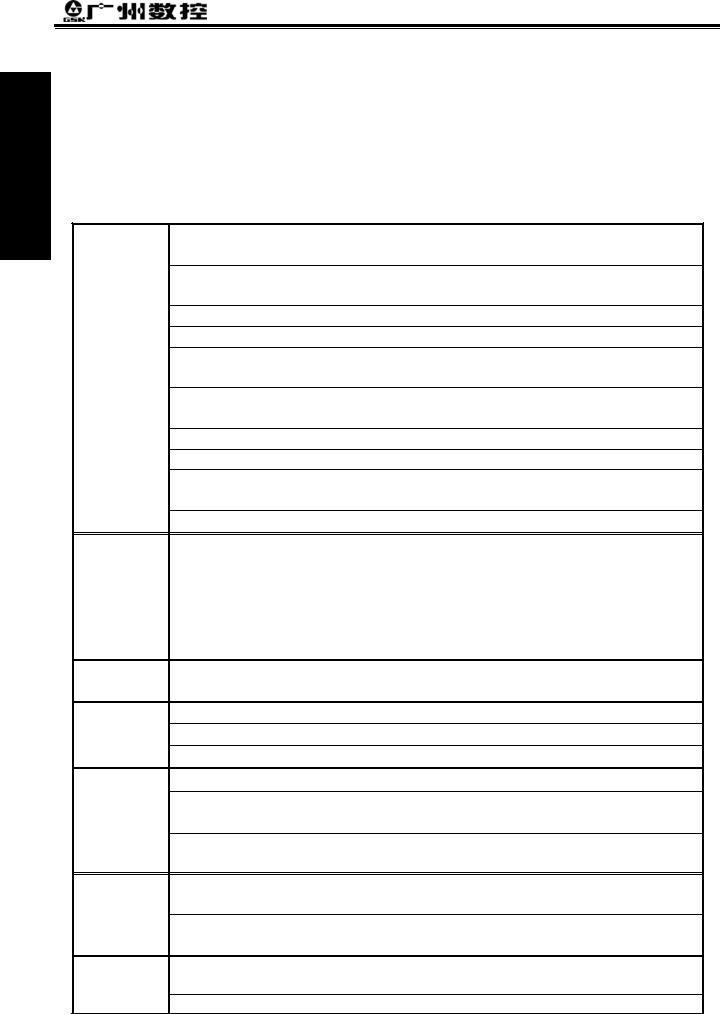
GSK980MD Configuration Software: GSKCC
The GSKCC is run in the condition of the WIN98/2000/XP operation system, so, the machine manufacturer can perform the GSK980MD ladder diagram, parts program, parameter, pitch error compensation data and tool compensation data on the PC to finish the upload and download of the files between PC and GSK980MD system.
-4
Chapter 1 Programming Fundamental
Programming 1 Part
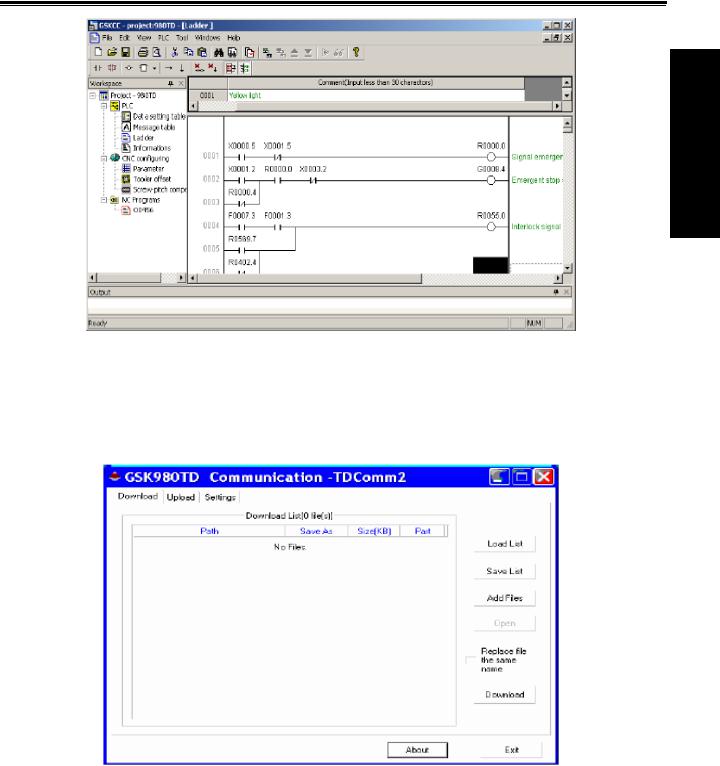
GSK980MD Communication Software: TDComm
The TDComm is run in the condition of the WIN98/2000/XP, which is provided to the end user to finish the bidirectional transmission of the parts program, the parameter, pitch error compensation data and tool compensation data between PC and CNC.
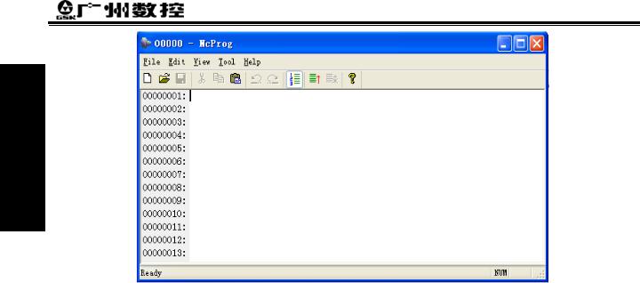
GSK980MD DNC Communication Software: GcodeEdit
The GcodeEdit is run in the condition of the WIN98/2000/XP. which is provided to the manufacturer or the end user to finish the DNC program transmission between PC and CNC.
-5
GSK980MD Milling CNC System
Programming 1 Part
-6
Chapter 1 Programming Fundamental
1.2Execution of the Program
1.2.1Order of the program execution
The GSK980MD can not open two or more programs at the same time; it can run the current opened program in Auto mode. So, the GSK980MD can perform only one program at any time. The cursor is located at the beginning of the row of the first block when a program is opened, and the cursor can be moved in Edit mode. Start the execution of
the program from the block the current cursor is located at by using the cycle start signal ( key on the panel or external cycle start key) in the halt state of Auto mode, usually, the blocks are executed one by one in the order of the blocks editing, and the execution is stopped till the M02 or M03 code is executed. The cursor is moved along with the program execution. The program execution sequence or state will be changed in the following conditions:
The program execution will be stopped if the |
RESET |
key or the Emergency Stop button is pressed; |
The program execution will be stopped if the CNC alarm or PLC alarm is generated;
The operation mode is switched to the MDI or Edit mode when the program is being executed; or the program is started from the block the cursor is located at when switching to Auto mode by single block stop
(The program pauses after the current block executed), and then the  key is pressed or external cycle start signal is ON;
The operation mode is switched to Manual, MPG, Step and Machine zero mode when the program being executed. The program is held on, then switching to Auto mode, and then the communication is switched
on when the  key is pressed or external cycle start signal is ON, the program is operated from the halt position;
The program pauses when pressing FEED HOLD key or external pause signal is cut off, the program is operated from stopped position when pressing  key or external cycle start signal is ON;
The program pauses after each block is executed when the single block switch is opened, pressing  key or switching on external cycle start signal is needed, program is executed continuously from the next block;
The skip switch of the block is opened which it is skipped or inexecuted when the “/” is in front of the block;
The skip object block is turned to when the G65 skip command is performed
When M98 or M9000~M9999 command is performed, to call corresponding subprogram or macro run; the subprogram or macro run is ended, when the M99 command is to be performed, to call the next block run as returning to the mainprogram (If M99 command specifies the return object block number, then run by skipping to object block);
When the M99 command is performed in main program (its run is not started up because others program calls), then returning to the program first stage to continue run, so the current program will be run circularly.
Programming 1 Part
-7

Programming 1 Part
GSK980MD Milling CNC System
1.2.2 Execution order of command word within block
R, M, S and T, most command words M, S and T are explained by NC before sending to PLC for processing, the other command words are processed by NC directly. M98, M99, M9000~M9999, as well as S command word for spindle speed by rev/min, m/min units are all processed by NC directly.
When G command shares a same block with M00, M01, M02 and M30, the NC performs M command after finishing G command, and then sending the corresponding M signal to PLC for processing.
When the G command shares a same block with the M98, M99, M9000~M9999, these M command words are performed by NC after it finishes the G command (the M signal not sent to PLC).
As the M, S and T command words processed by PLC and the G command words are sharing the same block, the M, S and T command words are performed with the G command words at the same time which they are determined by PLC program (ladder diagram), or the M, S and T command words are performed after the G command is finished. As for the performance order of the command words, refer to the explanation of the machine tool manufacturer.
-8

Chapter 2 MSTF Command
CHAPTER 2 MSTF COMMAND
2.1M Command (Miscellaneous Function)
The M command word composed by command address M and 1~2 or 4 digits after the command M is used for controlling the program execution or outputting M code to PLC.
M □□□□
Command value (00~99 9000~9999 leading zero can be omitted) Command address
M98, M99 and M9000~M9999 are independently processed by NC, and the M code is not output to PLC.
The M02 and M03 are defined as program END command by NC, at the same time it also gives the M code to PLC for using the I/O control (close spindle, close cooling etc.).
The PLC program can not change the meaning of the above-mentioned commands when the M98, M99 and M9000~M9999 are regarded as program CALL commands and the M02 and M30 are regarded as program END commands. The codes of other M commands are all given to PLC program for specifying the command function; please refer to the manual issued by machine tool manufacturer.
One block only has one M command. The CNC alarm occurs when two or more M commands are displayed in one block.
|
Table 2-1 M command table for program execution |
|
Commands |
|
Functions |
|
|
|
M02 |
|
End-of-Run |
M30 |
|
End-of-Run |
M98 |
|
Subprogram call |
|
|
Return from the Subprogram; the program will be circularly executed |
M99 |
|
if the command M99 is used for main program ending (namely, the |
|
|
current program is not called by other programs). |
M9000 M9999 |
Call macro program (Program No. more than 9000) |
|
Programming 1 rtPa
2.1.1EP (End of program) M02
Format: M02
Command function: The M02 command is executed in the Auto mode. The automatic run is ended when the other commands of current block are executed; now in order to not return to the program beginning, the cursor is stop at block which the M02 located. If the program is executed again the cursor should be stopped at the beginning of the program.
The function of command M02 also can be defined by the PLC ladder diagram other than the abovementioned functions which are processed by NC. The standard ladder diagram can be defined as: the current input state of CNC is not change after the command M02 is executed.
-1
Programming 1 rtPa
GSK980MD Milling CNC System
2.1.2End-of-run M30
Format: M30
Command function: If M30 command is executed in the Auto mode, the automatic run is ended when the other commands of current block are executed; the system cancels the nose radius compensation and the cursor returns to the beginning of the prgram when the machine pieces number is added by 1 (It is up to parameter if the cursor returns to the beginning).
The cursor is not return to the beginning of the program when the BIT4 of parameter No.005 is set to 0 in CNC; when it is set to 1, the prgram is finished, so the cursor returns to the beginning of the program at once.
The function of command M30 can be defined by the PLC ladder diagram other than the abovementioned functions processed by NC. The standard ladder diagram can be defined as: to close the M03, M04 or M08 signal output after the M30 command is executed, at the same time the M05 signal is given.
2.1.3Subprogram call M98
Format M98 P○○○○□□□□
The called subprogram No. 0000 9999 .The leading zero of subprogram can be omitted when the call frequency are not given; the subprogram No. should be 4 digits when the calling frequency is given;
Calling frequency 1-9999 calling for once, the input can be omitted
Command function: when the M98 command is executed in the Auto mode, CNC calls and executes the subprogram specified by P, which can be performed 9999 times at most, when the other commands of current block are executed. The M98 command is disabled in MDI.
2.1.4Return from subprogram M99
Format M99 P○○○○
The block No. (0000 9999) to be executed when a mainprogram is returned, the leading zero can be omitted.
Command function: (in subprogram) as the other commands of current block are executed, the block specified by P is performed continuously when the main program is returned. The next block is performed continuously by calling current subprogram of M98 command when returning to the mainprogram; because of the P is not given. If the main program is ended by using the M99 (namely, the current program is not called by other programs for execution), the current program will be run circularly. So, the M99 command is disabled in MDI.
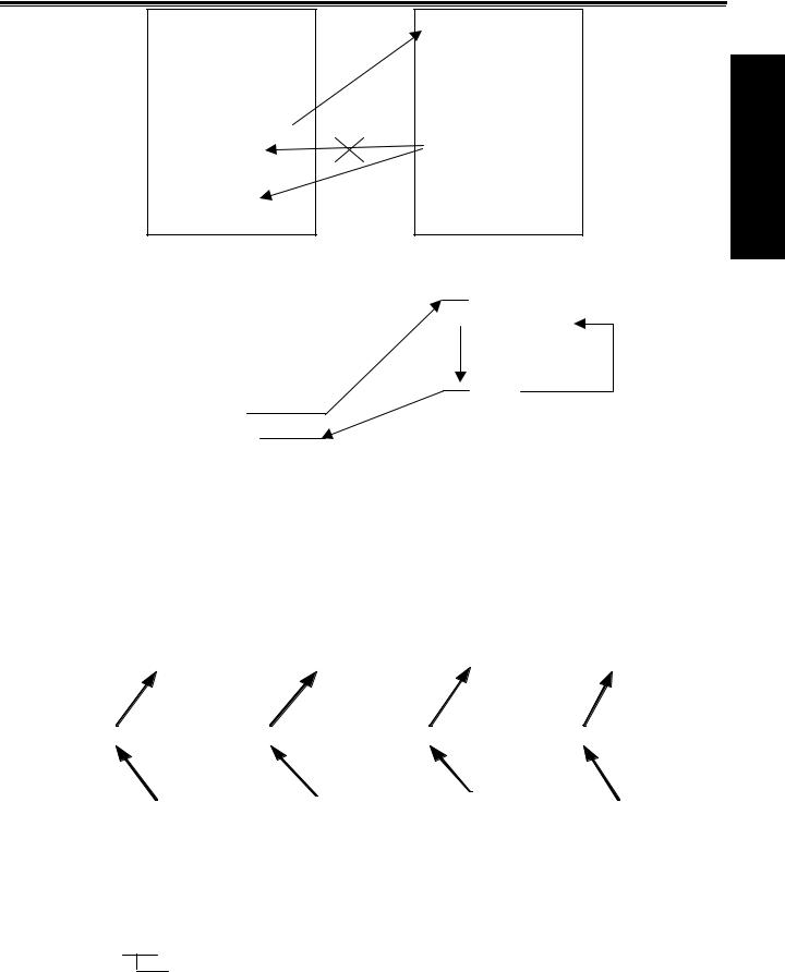
Example: Fig. 2-1shows that the execution route of the subprogram is called (the P command within M99). Fig. 2-2 shows that the execution route of the subprogram is called (the P command is not in M99).
-2
Chapter 2 MSTF Command
O1009
N0010 ………; N0020……….; N0030……….; N0040 M98 P1010; N0050……….; N0060……….; N0070……….; ……..
O1010
N1020………; N1030………;
………
………
N1100 M99 P0070;
%
|
|
Fig. 2-1 |
|
|
|
|
|
|
|
0001; |
|
|
|
1006; |
G92 X100 Z100; |
|
Call |
G90 G1 X50 Z50; |
|
M3 S1; |
|
|
|
G91 X100 Z200; |
G0 X0 Z0; |
|
|
|
X30 Z-15 F250; |
G1 X200 Z200 F200; |
|
|
|
M99; |
M98 P21006; |
|
Return |
% |
|
G0 X100 Z100; |
|
|
||
M5 S0; |
|
|
|
|
M30; |
|
|
|
|
% |
|
|
|
|
|
|
|
|
|
|
|
|
|
|
|
|
|
Mainprogram |
|
Fig. 2-2 |
Subprogram |
|
||
|
|
|
|
|
|
|
|||
|
This GSK980MD can calls quadruple subprogram, namely, the other subprogram can be called from the |
||||||||
subprogram. (See Fig. 2-3) |
|
|
|
|
|
|
|||
|
M a in p ro g ra m |
|
S u b p ro g ra m |
|
S u b p ro g ra m |
|
S u b p ro g ra m |
S u b p ro g ra m |
|
|
|
|
|
|
|
|
|
|
|
|
O 1 0 0 1 |
|
O 1 0 0 2 |
|
O 1 0 0 3 |
|
O 1 0 0 4 |
|
O 1 0 0 5 |
|
. . . |
|
. . . |
|
. . . |
|
. . . |
|
. . . |
|
. . . |
|
. . . |
|
. . . |
|
. . . |
|
. . . |
|
. . . |
|
. . . |
|
. . . |
|
. . . |
|
. . . |
|
M 9 8 P 1 0 0 2 ; |
|
M 9 8 P 1 0 0 3 ; |
|
M 9 8 P 1 0 0 4 ; |
|
M 9 8 P 1 0 0 5 ; |
|
M 9 8 P 1 0 0 5 ; |
|
. . . |
|
. . . |
|
. . . |
|
. . . |
|
. . . |
|
. . . |
|
. . . |
|
. . . |
|
. . . |
|
. . . |
|
. . . |
|
. . . |
|
. . . |
|
. . . |
|
. . . |
|
. . . |
|
. . . |
|
. . . |
|
. . . |
|
. . . |
|
M 3 0 ; |
|
M 9 9 ; |
|
M 9 9 ; |
|
M 9 9 ; |
|
M 9 9 ; |
|
|
|
|
|
|
|
|
|
|
|
|
S in g le n e s tific a tio n |
D o u b le n e s tific a tio n |
T rip lic a te n e s tific a tio n Q u a d ru p le n e s tific a tio n |
|||||
Fig. 2-3 Subprogram nestifications
Programming 1 rtPa
2.1.5Macro program call M9000~M9999
Format M□□□□
9000 9999
Command function: Call the macro program which is corresponded by the command value O9000 O9999 .
Macro program: Program 09000~09999 is special space obligated for the machine tool manufacturer for using editing and achieving speical function subprogram, which is called marco program. Two-level operation authority is
-3
Programming 1 Part
GSK980MD Milling CNC System
needed when editing the program 09000~09999, the user can not modifiy or operate the macro program but the macro calling command if his authority is 3~5 level. So the M9000~M9999 command operates invalidly in MDI.
2.1.6M command defined by standard PLC ladder diagram
The M commands other than the abovementioned commands (M02, M03, M98, M99, M9000~M9999) are defined by PLC. The M commands are defined by standard PLC hereinafter. This GSK980MD milling machine is used for machine control. About the function, meaning, control time sequence and logic etc. of the M command, refer to the manual issued by the machine tool builder.
M command specified by standard PLC ladder diagram
Commands |
Functions |
Remarks |
|
M00 |
Program pause |
|
|
M03 |
Spindle CCW |
Function interlock, |
|
M04 |
Spindle CW |
||
state hold |
|||
*M05 |
Spindle stop |
||
|
|||
M08 |
Coolant on |
Function interlock, |
|
*M09 |
Coolant off |
state hold |
|
M32 |
Lubrication on |
Function interlock, |
|
*M33 |
Lubrication off |
state hold |
Notes: The command with “*” specified by standard PLC is valid when the power is turned on.
2.1.7Program stop M00
Format: M00
Command function: the program is stopped after executing the M00 command, the “pause” is displayed; the program will continue when the key of Cycle Start is pressed.
2.1.8 Spindle CCW, CW, stop control M03, M04 and M05
Format: M03; M04; M05;
Command function: M03: spindle forward rotation (CCW); M04: spindle reverse rotation (CW); M05: spindle stop.
Note: The control time sequence and logic of M03, M04 and M05 are specified by standard PLC program, refer to the Appendix of this manual.
2.1.9Coolant control M08, M09
Format: M08; M09;
Command function: M08: cooling on; M09: cooling off.
Note: The control time sequence and logic of M08 and M09 are specified by standard PLC program, refer to the Appendix of this manual.
-4
Chapter 2 MSTF Command
2.1.10Lubricant control M32, M33
Format: M32; M33;
Command function: M32: lubrication on; M33: lubrication off.
Note: The control time sequence and logic of M08 and M09 are specified by standard PLC program; refer to the Appendix of this manual.
Programming 1 Part
-5
Programming 1 rtPa
GSK980MD Milling CNC System
2.2Spindle Function
The spindle speed is controlled by S command, there are two ways to control spindle speed for GSK980MD. Spindle speed switching value control mode: the S□□ (2-digit command value) command is processed by PLC
program for exporting the switching value signal to machine, so that the step speed change of the spindle is achieved. Spindle speed analog voltage control mode: the actual spindle speed is specified by the S□□□□ (4-digit command value), the NC outputs the 0~10V analog voltage signal to the spindle servo device or transducer for
achieving the stepless speed regulating of the spindle.
2.2.1Spindle speed switching value control
The spindle speed is on switching value control when the BIT4 of bit parameter NO.001 is set to 0. One block only has one S command. The CNC alarm occurs when there are two or more S commands displayed in block.
When the S command shares the same block with the command word, the performance sequence is defined by PLC program. For details, refer to the manual issued by the machine tool builder.
This GSK980MD milling machine is used for machining control when the spindle speed switching value is controlled. The time sequence and logic for S command should be referred by the manual issued by the machine tool builder. The following S command is defined by GSK980MD standard PLC, for reference only.
Command format: S□□
00 04 (the leading zero can be omitted): 1 4 gears spindle speed switching value control.
In spindle speed switching value control mode, the FIN signal is returned after the set time of data parameter No.081 is delayed after the code signal of S command is sent to PLC. Now the time is called execution time of S code.
S code performs Delay time |
Subsequent command word or block |
performs
The S01, S02, S03 and S04 output states are invariable when the CNC is reset.
The S1~S4 commands are ineffective output when the CNC is switched on. An arbitrary command is performed from S01, S02, S03 and S04, the corresponding S signal output is effective and held on, at the same time the other 3 S signal output are cancelled. The S1~S4 output are cancelled when performing the S00 command, only one of S1~S4 is effective in the meantime.
2.2.2Spindle speed analog voltage control
The spindle speed is analog voltage control when the BIT4 of current bit parameter is set to 1 Format S OOOO
0000 9999 (leading zero can be omitted): Spindle speed analog voltage control
Command function: The CNC outputs 0~10V analog voltage to control the spindle servo or transducer for achieving the stepless speed regulating of the spindle when the spindle speed is set. The S command value is not memorized when the power is turned off; and then the parameter recovers to 0 when the power is turned on.
-6

Chapter 2 MSTF Command
The CNC owns four mechanical spindle shifts function. Counting the corresponding analog voltage value specified by the speed based upon the current set value (corresponding to data parameter No.037~No.040) of the top speed (output analog voltage is 10V) of the spindle shift when the S command is performed, then output the voltage value to spindle servo or transducer, so that the consistency of actual speed and required speed of the spindle are controlled.
The analog voltage output is 0V when the CNC is switched on. The output analog voltage value is invariable (Unless the cutting feed in constant linear speed control and the absolute value of X axis absolute coordinate value are changed) after the S command is executed. The analog voltage output is 0V when the command S0 is executed. And the analog voltage output value is invariable when the CNC is reset or at urgent stop.
The parameter related to spindle speed analog voltage control:
Data parameter No.021: the output voltage offset for spindle top speed (the output analog voltage is 10V); Data parameter No.043: the voltage offset for the zero spindle speed (the output analog voltage is 0V); Data parameter No.037~No.040: The top speed for spindle 1~4 shifts (the output analog voltage is 10V);
Programming 1 Part
2.2.3Spindle override
The spindle actual speed can be modified by using spindle override when the spindle speed analog voltage control is effective, the actual speed modified by spindle override is limited by the top speed of current spindle shift, and also it is controlled by the lowest spindle limitation value and the top spindle limitation value in constant linear speed control mode.
This NC offers 8-level spindle override (50%~120%, the change is 10% per level). The actual level and the modificative mode of the spinde override are defined by PLC ladder diagram. Refer to the manual issued by the machine tool builder when attempting to use it. The following is function description is GSK980MD standard PLC ladder diagram, for reference only.
The spindle override defined by GSK980MD standard PLC ladder digaram has 8 levels. The spindle actual real-time speed can be adjusted by using the spindle override key in the command speed range of 50%~120%, the spindle override will be memorized when the power is turned off. Refer to the OPERATION of this manual for modification operation of the spindle override.
-7

Programming 1 Part
GSK980MD Milling CNC System
2.3Tool Function
There is no tool function in this 980MD system.
2.4Feeding Function
2.4.1Cutting feed (G94/G95, F command)
Format: G94F_; (F0001~F8000, leading zero can be omitted, for feed speed per minute, mm/min)
Command function: The cutting feedrate is specified by mm/min, G94 is modal G command. If the current mode is G94 that it needs no G94 any more.
Format: G95F_; (F0.0001~F500, leading zero can be omitted)
Command fucntion: The cutting feedrate is offerred by the unit of mm/rev., G95 is modal G command. The G95 command can be omitted if the current mode is G95. When the CNC performs G95 F_, the cutting feedrate is controlled by feedrate command based on the multiplication of F command value (mm/rev) and current spindle speed (rev/min). The actual feedrate varies with the spindle speed. The spindle cutting feedrate per revolution is specified by G95 F_, the even cutting line can be formed on the face of workpiece. It is necessary to install spindle encoder when the G95 mode is operated.
The G94 and G95 are modal G commands at the same group, one of them is available only. The G94 is initial state G command, so, it defaults the G94 when the CNC is switched on. The following below shows the conversion formula of feed value per rev. and feed value per min:
Fm = Fr×S
Thereinto: Fm: feed value per minute (mm/min); Fx: feed value per revolution (mm/r); S: spindle speed (r/min).
The feedrate value is set by the CNC bit parameter No.053 when the CNC is switched on, the F value is invariable after the F command is executed. The feedrate is 0 after F0 is executed. The F value is invariable when CNC is reset or at urgent stop.
Note: In G95 mode, the cutting feedrate will be uneven when the spindle speed is less than 1 rev. /min. The following error will exist in the actual feedrate when the spindle speed vibration occurs. To guaranteen the machine quality, it is recommanded that the spindle speed selected in machining is not less than the lowest speed of available torque exported by spindle servo or transducer.
Cutting feed: The CNC makes tool movement path and the path (linear or circular arc) defined by command into consistency (The circular interpolation can be performed by two axes in selected plane when it is circular arc, the helical interpolation is formed by the third axis linear interpolation linkage), by which, the CNC controls three directions movement for X axis, Y axis and Z axis at the same time. The instantaneous speed of movement path in a tangential direction is consistent with the F command value, so this is called CUTTING FEED or INTERPOLATION. The cutting feedrate is supplied by F command, which it is disassembled to each interpolation axis according to the programming path when the CNC performs the interpolation command (cutting feed).
-8
Chapter 2 MSTF Command
Linear interpolation: The CNC can controll the instantaneous speed in the directions of X axis, Y axis and Z axis, so the vector resultant speed in these three directions are equal to the F command value.
f x |
= |
d x |
•F |
||
+d y2 +d z2 |
|||||
|
|
d x2 |
|
||
f y |
= |
d y |
• F |
||
|
|||||
|
|
d x2 + d y2 + d z2 |
|
||
f z |
= |
|
d z |
• F |
|
d x2 + d y2 + d z2 |
|||||
|
|
|
|||
F is vector resultant speed for the instantaneous speed in X, Y and Z axis directons
The dx is instantaneous increment of the X axis, the fx is instantaneous speed of X axis.
The dy is instantaneous increment of Y axis, the fy is instantaneous speed of Y axis.
The dz is instantaneous increment of Z axis, the fz is instantaneous speed of Z axis.
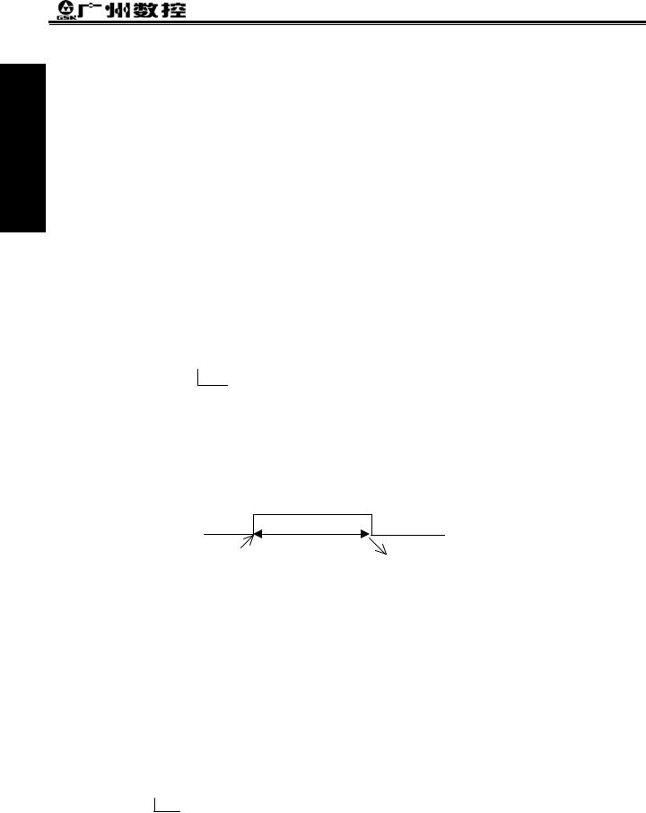
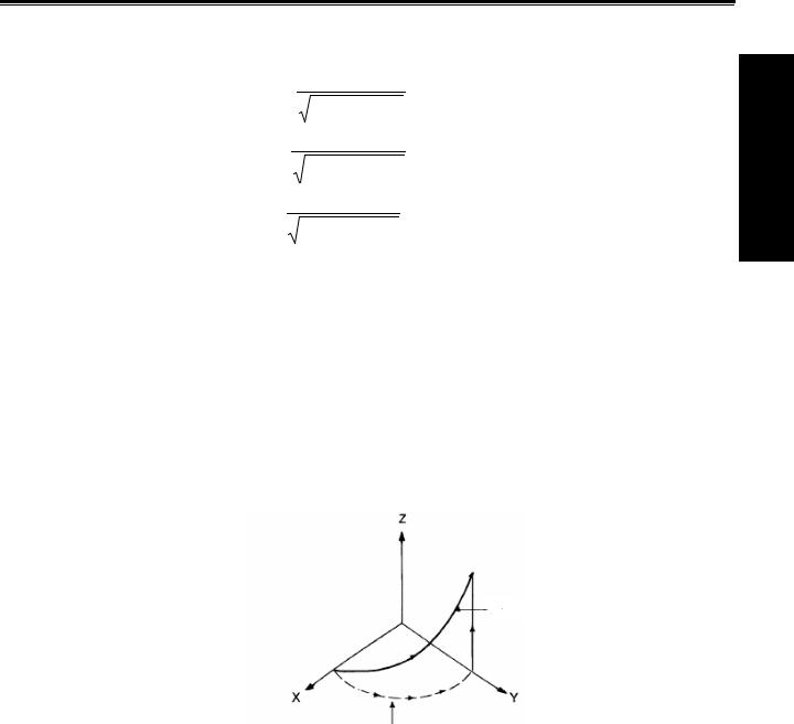
Circular interpolation (helical interpolation): Performing the arc interpolation in selected plane, the third axis performs linear interpolation, so the F value is circular interpolation speed. An interpolation of linear and circular arc has the following relation when the linear interpolation speed is f:
f =F× linear axis length circular arc length
Programming 1 rtPa
Toolpath
Feedrate along the circle betw een 2 arc interpolation axes is the specified one .
There are 16 levels feedrate override (0~150%, 10% per level) are offerred by NC. The actual feedrate series, the memory performed or not when the power is turned off and the method of overriding are defined by PLC ladder diagram. Refer to the manual issued by the machine tool builder. The function description of GSK980MD standard PLC ladder diagram is as follows, for reference only.
By using the feedrate override key of the machine panel or external override switch it can performs real-time modification for the cutting feedrate. The actual cutting feedrate can be adjusted in the range of command speed 0~150%, here, the feedrate is memorized when the power is turned off. How to operate the cutting feedrate adjustment, refer to Chapter 3 OPERATION of this manual.
Related parameter:
CNC parameter No. 029: the exponential acceleration or deceleration time constant of cutting feed and manual feed.
CNC parameter No.030: the initial (terminal) speed of exponential acceleration or deceleration for cutting feed. CNC parameter No.031: the upper limit value (X axis, Y axis and Z axis are same) of the cutting feedrate.
-9

Programming 1 Part
GSK980MD Milling CNC System
2.4.2Manual feed
Manual feed: This GSK980MD can perform positive/negative movement of X, Y or Z axis by the current manual feedrate in the Manual mode. X axis, Y axis and Z axis can be moved at one time.
This NC offers 16 levels (0~150%, 10% each time) manual feedrate (override), see the following table 2-2. The actual feedrate series and modification mode or the like in manual feeding, are defined by PLC ladder diagram. Refer to the manual issued by the machine tool builder. The function description of GSK980MD standard PLC ladder diagram is as follows, for reference only.
Table 2-2
Feedrate |
0 |
10 |
20 |
30 |
40 |
50 |
60 |
70 |
80 |
90 |
100 |
110 |
120 |
130 |
140 |
150 |
|
override(%) |
|||||||||||||||||
|
|
|
|
|
|
|
|
|
|
|
|
|
|
|
|
||
Manual |
|
|
|
|
|
|
|
|
|
|
|
|
|
|
|
|
|
feedrate |
0 |
2.0 |
3.2 |
5.0 |
7.9 |
12.6 |
20 |
32 |
50 |
79 |
126 |
200 |
320 |
500 |
790 |
1260 |
|
(mm/min) |
|
|
|
|
|
|
|
|
|
|
|
|
|
|
|
|
Note: The manual feedrate of X axis is diameter variation per minute; the feedrate defined by GSK980MD standard PLC ladder diagram is memorized when the power is turned off.
Related parameter: Data parameter No.029: for exponential acceleration or deceleration time constant in manual feed.
Data parameter No.041: for speed lower limit of acceleration or deceleration in manual feed.
2.4.3MPG/ Step feed
MPG feed: This GSK980MD can move positively or negatively in X, Y or Z axis by current increment in the MPG mode. Only one of the axes can be moved at one time.
Step feed: This GSK 980MD can move positively or negatively for X, Y or Z axis by current increment in the Step mode. One of the axes can be moved only at one time.
Only one mode is effective for the MPG or step mode at one time, it is up to Bit3 of CNC bit parameter No.001. This NC offers 4 steps (0.001mm, 0.01mm, 0.1mm and 1mm) MPG/ step increment. The actual MPG/ step increment series, the selection of increment and current effective axis or the like, are defined by PLC ladder diagram.
Refere to the manual issued by the machine tool builder.
Related parameter: Data parameter No.029: for exponential acceleration or deceleration time constant of cutting feed and manual feed.
Data parameter No.041: for initial or terminal speed of exponential acceleration or deceleration in manual feed.
2.4.4Automatic acceleration or deceleration
This GSK980MD performs automatically acceleration or deceleration in order to achieve the smooth transition of the speed at the beginning of the axis movement or before the movement stops; this will diminish the impact when the movement is start or stop. This GSK980MD adopts kinds of acceleration or deceleration as follows:
Rapid traverse: linear type front acceleration or deceleration Cutting feed: exponential type rear acceleration or deceleration Manual feed: exponential type rear acceleration or deceleration MPG feed: exponential type rear acceleration or deceleration Step feed: exponential type rear acceleration or deceleration
-10

Chapter 2 MSTF Command
|
|
|
|
|
|
|
|
|
Speed by acceleration or |
|
|
|
|
||||
|
|
|
Speed after interpolation |
|
|
|
|
|
|
||||||||
|
|
|
|
|
deceleration control |
|
|
|
|
||||||||
|
|
|
|
|
|
|
|
|
|
|
|
|
|
|
|
|
|
|
|
|
|
|
|
|
|
|
|
|
|
|
|
|
|
||
|
|
|
|
|
|
|
|
|
|
|
|
|
|
X axis |
|
||
|
|
|
|
|
Acceleration or |
|
|
|
|
|
|
|
|
||||
|
|
|
|
|
|
|
|
Drive control |
|
|
|
||||||
|
|
|
|
|
|
|
|
|
|
|
|||||||
CNC |
|
|
|
|
deceleration control |
|
|
|
|
motor |
|
||||||
|
Pulse |
|
|
|
|
|
|
||||||||||
|
|
|
|
|
|
|
|
||||||||||
|
|
|
|
|
|
|
|||||||||||
comm |
|
|
|
|
|
|
|
|
|
|
|
|
|
|
|
||
|
|
|
|
|
|
|
|
|
|
|
|
|
|||||
|
assignment |
|
|
|
|
|
|
|
|
|
|
|
|
|
|
||
|
|
|
|
|
|
|
|
|
|
|
|
|
Y axis |
|
|||
ad |
|
|
Acceleration or |
|
|
|
|
|
|
|
|
||||||
|
(Interpolati |
|
|
|
|
Drive control |
|
|
|
|
|||||||
|
|
|
|
|
|
|
|
motor |
|
||||||||
|
|
|
deceleration control |
|
|
|
|
|
|
||||||||
|
|
on) |
|
|
|
|
|
|
|
|
|||||||
|
|
|
|
|
|
|
|
|
|
|
|
|
|
|
|
||
|
|
|
|
|
|
|
|
|
|
|
|
|
|
|
|
||
|
|
|
|
|
|
|
|
|
|
|
|
|
|
|
|
||
|
|
|
|
|
|
|
|
|
|
|
|
|
|
Z axis |
|
||
|
|
|
|
|
|
Acceleration or |
|
|
|
|
|
|
|
|
|||
|
|
|
|
|
|
|
|
|
Drive control |
|
|
|
|
||||
|
|
|
|
|
|
deceleration control |
|
|
|
|
motor |
|
|||||
|
|
|
|
|
|
|
|
|
|
|
|
||||||
|
|
|
|
|
|
|
|
|
|
|
|
||||||
|
|
|
|
|
|
|
|
|
|
|
|
|
|
|
|
|
|
Fig. 2-9
FR: Rapid traverse rate
Set by data parameter No.022,
No.023 and No.024 parameter
TR: Rapid traverse acceleration or deceleration time constant
Set by data parameter No.025, No.026 and No.027 parameter
Fig. 2-10 Curve for rapid traverse
Feedrate
Feedrate
Acceleration or deceleration time constant for cutting feedrate
Time
FC: feedrate
TC: The acceleration or deceleration time constant of cutting feedrate (Data parameter No.029)
Fig. 2-11 Curves for cutting and manual feedrate
Programming 1 Part
-11
GSK980MD Milling CNC System
Programming 1 rtPa
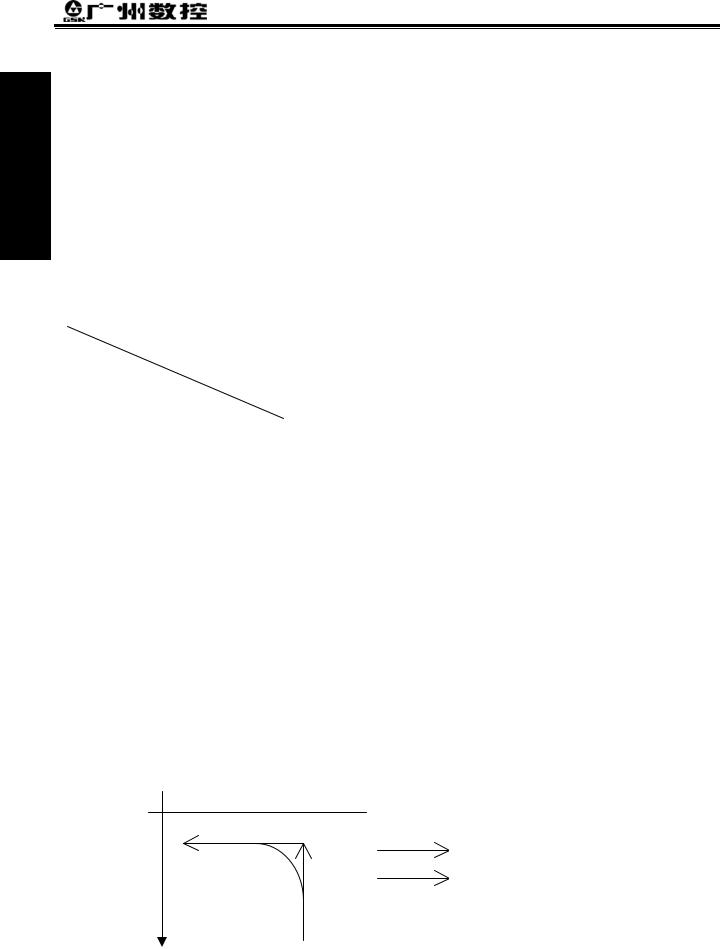
When the cutting feed is performed, this GSK980MD adopts exponential rear acceleration or deceleration, an arc transition will be formed for the acceleration or deceleration at the meeting point of the path for the adjacent two cutting feed blocks, when the BIT3 of the bit parameter No.007 is set to 0. A contour error exists between the actual tool path and the programmed path when the positioning is not enough accurate at the meeting point of the two paths. In order to avoid this kind of error, the exact stop command (G04;) can be inserted between the two blocks or the BIT3 of the CNC bit parameter No.007 is set to 1. Now, the previous block is decelerated to zero speed and it is positioned to the end of the block, and then the next cutting feed block is performed. The following block can be performed because each block is accelerating from the initial speed and then decelerating to zero at last. If the program time is increasing, it may cause the lower machining efficiency.
The BIT3 of bit parameter No.007 is set to 0, the transition between two adjacent blocks is processed according to the table 2-3.
Table 2-3
Previous |
|
|
|
block |
Rapid positioning |
Cutting feed |
|
Next block |
|
||
|
|
|
|
|
|
|
Without move |
Rapid positioning |
X |
X |
X |
|
|
|
|
Cutting feed |
X |
O |
X |
|
|
|
|
Without move |
X |
X |
X |
|
|
|
|
Note: X: The subsequent block is perfomed after the previous block is accurately positioning at the end of he block.
O: Each axis speed is transitted according to the acceleration or deceleration between the adjacent blocks; an arc transition is formed at the meeting point of the tool path. (Inaccurate positioning)
Example (The BIT3 of the bit parameter is set to 0)
G91 G01*-100; (X axis move negatively)
Z-200; |
(Z axis move negatively) |
Y-300; |
(Y axis move negatively) |
 Z
Z
Programmed path
Actual movement tool path
X
Fig. 2-12
-12

Chapter 3 G Command
CHAPTER 3 G COMMAND
3.1Brief
The G command is composed by the command address G and the1 to 3 digits command value after the command G. Many kinds of operations are specified such as tool movement relative to workpiece, coordinate set, etc.See Table 3-1 for G commands.
G □□□
Command value (00~143, the leading zero can be omitted)
 Command address G
The G command words can be classified to 11 groups such as 00, 01, 02, 03, 05, 06, 07, 08, 09, 10 and 14. They share the same block except for 01 and 00 groups, different groups G commands can be defined at the same block. The last G command is valid when two or more same group G commands are introduced at the same block. Different G command groups without common parameter (command word) can be defined at the same block, and their functions are simultaneously valid regardless of sequence. If the G command or the optional G command other than Table 3-1 is employed, alarm occurs.
Table 3-1 G command word list
Command words |
Groups |
Functions |
Remarks |
|
|
|
|
|
|
G04 |
|
Dwell, exact stop |
|
|
|
|
|
|
|
G28 |
|
Machine zero return |
|
|
|
|
|
|
|
G29 |
|
Return from reference point |
Non-modal G |
|
|
00 |
|
||
G30 |
2nd, 3rd and 4th reference point return |
|||
command |
||||
|
|
|
||
G31 |
|
Skip function |
||
|
|
|||
|
|
|
|
|
G92 |
|
Coordinate system set |
|
|
|
|
|
|
|
G65 |
|
Macro |
|
|
|
|
|
|
|
G00 (initial G command) |
01 |
Rapid traverse |
Modal G |
|
G01 |
|
Linear interpolation |
command |
|
|
|
|
|
|
G02 |
|
Circular interpolation (CW) |
|
|
|
|
|
|
|
G03 |
|
Circular interpolation (CCW) |
|
|
|
|
|
|
|
G73 |
|
Peck drilling cycle |
|
|
G74 |
|
Left-hand (counter) tapping cycle |
|
|
|
|
|
|
|
G80 (initial G command) |
|
Canned cycle cancellation |
|
|
G81 |
|
Drilling cycle (spot drill cycle) |
|
|
G82 |
|
Drilling cycle (counterbore cycle) |
|
|
|
|
|
|
|
G83 |
|
Peck drilling cycle |
|
|
G84 |
|
Tapping cycle |
|
|
G85 |
|
Boring cycle |
|
|
|
|
|
|
|
G86 |
|
Drilling cycle |
|
|
G88 |
|
Boring cycle |
|
Programming 1 artP
-1

GSK980MD Milling CNC System
|
|
Command words |
Groups |
Functions |
Remarks |
|
|
|
|
|
|
|
|
G89 |
|
Boring cycle |
|
Part |
|
|
|
||
|
G110 |
|
Circular groove inner rough-milling CW |
|
|
|
|
|
|
||
|
|
|
|
|
|
1 |
|
G111 |
|
Circular groove inner rough-milling CCW |
|
|
|
|
|
|
|
Programming |
|
G112 |
|
Circular groove inner fine-milling CW |
|
|
|
|
|
|
|
G134 |
|
Rectangle groove rough-milling CW |
|
||
|
|
G113 |
|
Circular groove inner fine-milling CCW |
|
|
|
G114 |
|
Excircle finish-milling CW |
|
|
|
G115 |
|
Excircle finish-milling CCW |
|
|
|
|
|
|
|
|
|
|
|
|
|
|
|
G135 |
|
Rectangle groove rough-milling CCW |
|
|
|
|
|
||
|
|
|
|
|
|
|
|
G136 |
|
Rectangle groove inner finish-milling CW |
|
|
|
|
|
|
|
|
|
G137 |
|
Rectangle groove inner finish-milling CCW |
|
|
|
|
|
|
|
|
|
G138 |
|
Rectangle outter finish-milling CW |
|
|
|
|
|
|
|
|
|
G139 |
|
Rectangle outter finish-milling CCW |
|
|
|
|
|
|
|
|
|
G17 (initial G command) |
|
XY plane selection |
Modal G |
|
|
G18 |
02 |
ZX plane selection |
|
|
|
command |
|||
|
|
|
|
|
|
|
|
G19 |
|
YZ plane selection |
|
|
|
|
|
||
|
|
|
|
|
|
|
|
G90 (initial G command) |
03 |
Absolute programming |
Modal G |
|
|
G91 |
Relative programming |
command |
|
|
|
|
|||
|
|
|
|
|
|
|
|
G94 (initial G command) |
05 |
Feed per minute |
Modal G |
|
|
G95 |
Feed per revolution |
command |
|
|
|
|
|||
|
|
|
|
|
|
|
|
G20 |
06 |
Data input in inch |
Modal power |
|
|
G21 |
Data input in metric |
down memorize |
|
|
|
|
|||
|
|
|
|
|
|
|
|
G40 (initial G command) |
|
Tool nose radius compensation cancellation |
Modal G |
|
|
G41 |
07 |
Tool nose radius compensation left |
|
|
|
command |
|||
|
|
|
|
|
|
|
|
G42 |
|
Tool nose radius compensation right |
|
|
|
|
|
||
|
|
|
|
|
|
|
|
G43 |
|
Tool length offset in + direction |
Modal G |
|
|
G44 |
08 |
Tool length offset in - direction |
|
|
|
command |
|||
|
|
|
|
|
|
|
|
G49 (initial G command) |
|
Tool length offset cancellation |
|
|
|
|
|
||
|
|
|
|
|
|
|
|
G140 |
|
Rectangle path serially punch CW |
|
|
|
G141 |
09 |
Rectangle path serially punch CCW |
Non-modal G |
|
|
|
|
command |
|
|
|
G142 |
Arc path serially punch CW |
||
|
|
|
|||
|
|
|
|
|
|
|
|
G143 |
|
Arc path serially punch CCW |
|
|
|
|
|
|
|
|
|
G98 (initial G command) |
10 |
Return to initial level in canned cycle |
Modal G |
|
|
G99 |
Return to R level in canned cycle |
command |
|
|
|
|
|||
|
|
|
|
|
|
|
|
G54 (initial G command) |
|
Workpiece coordinate system 1 |
|
|
|
G55 |
|
Workpiece coordinate system 2 |
|
|
|
|
|
|
|
|
|
G56 |
14 |
Workpiece coordinate system 3 |
Modal G |
|
|
G57 |
Workpiece coordinate system 4 |
command |
|
|
|
|
|||
|
|
|
|
|
|
|
|
G58 |
|
Workpiece coordinate system 5 |
|
|
|
|
|
|
|
|
|
G59 |
|
Workpiece coordinate system 6 |
|
|
|
|
|
|
|
-2
Loading...