


DA98D Digital AC Servo Drive Unit
User Manual
(V5.00)

 In this User manual, we will exert ourselves to describe each item related to operation of this drive unit. But due to reasons like limit in space and specific product uses, detailed description of unnecessary or impossible operation of this drive unit will be not included. Therefore, items that are not specially indicated in this manual will all be regarded as “impossible” or “disallowed” operations.
 Copyright of this manual belongs to GSK Equipment Co., Ltd, and any publication or copying of this manual by any unit or individual will be deemed as illegal behaviors. GSK Equipment Co., Ltd shall reserve the rights to ascertain legal liabilities of such behaviors.
1

Company Profile
Currently, GSK Equipment Co., Ltd (hereafter GSK for short) is a China's company with the domestically largest sale volumes of digital control systems. As the digital control industry base in Southern China and one of the 20 manufacturers of key equipment in Guangzhou, GSK is an undertaker of key projects listed in State 863 Supporting Technology for Middle-Grade Digital Control Industrialization. For more than a decade, the company has been dedicated to professional research & development, designing and manufacturing of such products as digital control systems for machine tools, digital control devices, drive units and servo motors. By launching campaign on popularization of digital control machine tools and developing trade in digital control machine tool, the company has developed into a large hi-tech company that integrates science, education, industry and trade into itself. Currently the company has more than 1,400 employees, among whom there are 4 doctors, more than 50 masters and over 500 engineering technicians (more than 50 technicians with senior professional titles). With a superior cost performance, GSK series of products have a very good sale in China and far in Southeastern Asia. Between 2000 and 2006, its market share has ranked No.1 in China for 7 consecutive years and its yield and sale volumes have led the peers for 7 consecutive years, which have consolidated its position as the biggest domestic production base of digital control system for machine tools.
Our main products include digital control equipment and devices like GSK series of machine tools, milling machine and digital control system for processing centers as well as Da98, DA98A, DA98B and DA98D series of full digital AC servo drive units, DY3 series of hybrid stepper motor driver, DF3 series of reaction stepper motor driver, GSK·SJT series of AC servo motors and CT-L digital control slipway. All the products follow state standards (international standards), industry standards and supplementary company standards (or internal control standards) in an all-round way. With powerful strength in technology development and improved production and quality assurance system, GSK has satisfied requirements of vast number of its customers with stable and reliable product quality. Its improved and sound
II

service mechanisms as well as the more than ten service offices set up in domestic and foreign provinces and cities can guarantee swift and convenient technical support and services within 24 to 48 hours. “Excellent products and outstanding services” have built a brilliant GSK. Abiding by the operation concept of “creating century-old company and molding gold brand”, GSK people will make unrelenting efforts to build a digital control industry base in
Southern China and push forward national digital control industry.
Field Technical Support Services
If you have problems that cannot be resolved through phone calls, you can receive our technical support on the spot. GSK will authorize technical support engineer to the field to resolve your technical problems.
III
Foreword
Foreword
Distinguished Customers,
It is a great honor for us to have you buy DA98D full digital AC servo drive units of GSK Equipment Co., Ltd.
This manual will introduce requirements and notes about operation of DA98D full digital AC servo drive unit.
!Improper operation will cause accidents, and the drive unit must be
operated by personnel with related qualifications
Please see to it that you have carefully read the manual prior to operation!
If there are changes to specifications and designs, we will not provide further notices.
Sincere thanks to your friendly support for using products of GSK Equipment Co., Ltd.!
Chinese version of all technical documents in Chinese and English languages is regarded as final.
IV
Foreword
●Due to improvement in products, contents of this manual will have some changes, for which we will not provide further notices.
●We will not be held accountable for any change made by the customer on the product and the warranty form will hereby go invalid.
Please give special attention to the following warning sings when reading the manual!
Warning
Attention
Wrong operation may lead to disastrous consequences---death or serious injury
Wrong operation may hurt the operator and the equipment may also be damaged!
|
|
|
|
|
Attention |
|
Improper operation may damage the product and equipment! |
|
|
|
|
|
|
|
|
V
Safety Warning
Safety Warning
Warning
●The product is not designed and manufactured to be used in machines or systems threatening personal safety.
●When selecting the product, the customers shall consider safety protection measures when designing and manufacturing their machines and systems, so as to avoid improper operation or irregular accidents of the product.
Acceptance
 Attention
● Damaged or broken-down products shall not be put into use.
Transportation
 Attention
●Products must be stored and transported under conditions for storage and transportation.
●Over-height piling shall not be allowed to prevent products from falling.
●When being transferred, the products concerned shall be properly packed.
●The servo motor shall not be moved by drawing its wire, motor shaft or encoder.
●Outside force and impact shall not be imposed on servo drive units and servo motors.
Installment
 Attention
Servo drive units and servo motors:
●Shall not be installed above or around combustible articles to prevent fire disaster.
●Shall avoid vibration. Impact shall be strictly forbidden.
●Shall not be installed when they are damaged or the parts are incomplete
Servo Drive unit:
●Must be installed in the control panel with sufficient degree of protection.
●Must keep sufficient intervals away from other equipment.
●Must have good conditions for heat emitting.
●Must prevent invasion of dust, corrosive air, conductive matters, liquid, combustible and
explosive substances.
Servo motors:
●Must be firmly installed to prevent loosening under vibration
●Must prevent motor and encoder from being damaged by the invaded liquids
●Shock on motor and motor shaft shall be strictly forbidden to prevent the encoder from being damaged.
●Load surpassing its limit shall not be imposed on the motor shaft.
VI
Safety Warning
Wiring
 Attention
●Personnel involved in wiring or examination must possess sufficient competence in this task.
●Wiring and examination must be conducted 5 minutes after the power is switched off.
●Servo drive units and servo motors must have good ground contact.
●Wrong voltage or electrode may cause explosion or operation accidents.
●Only after the servo drive unit and servo motor are properly installed can the wiring be conducted.
●Ensure insulation of the wire and avoid pressing the wire to prevent electric shock.
 Attention
●Wires must be connected in a correct and firm manner, otherwise, the servo motor may run by error or the equipment may be damaged due to bad contact.
●Terminals of U, V and W in servo motor shall not be connected reversely, nor be connected to AC power.
●Servo motor and servo drive unit must be directly connected and they shall not be connected with capacitor, inductor or wave filter.
●Prevent conductive fastening elements and wire heads from entering in the servo drive unit.
●The wire and substances not resistant to heat shall not close up to the servo drive unit’s radiator and servo motor.
●Continuous current diode connected in parallel to the DC relay for output signals shall not be connected reversely.
Commissioning and Runing
Attention
●Confirm that the servo drive unit and servo motor have been properly and firmly installed and that the power voltage and wiring are correct before switching on power.
●When commissioning, first run the servo motor without load; and after confirming that the parameters are correctly set, run the servo motor with load. In this process, improper operation shall be avoided to prevent the machine and equipment from being damaged.
Operation
 Attention
●An emergency stop circuit shall be coupled in to ensure that the equipment can immediately stop by timely switching off power in case of accidents.
●Confirm that the operation signal has been cut off before resetting an alarming signal; otherwise, the signal will be restarted suddenly.
●Servo drive unit must be operated together with its matched set of servo motor.
●Do not frequently switch off or on power of the servo drive unit to prevent the system from being damaged.
●The servo drive unit and servo motor may be very hot after long hours of operation, so do
Safety Warning
not touch the servo drive unit’s radiator or the servo motor with your hand within a short time after the power is off.
● Do not refit the servo drive unit.
Failure Handling
Attention
●Even after the power of servo drive unit has been cut off, the voltage will remain for some time. So do not dismantle the wire or touch the plate of terminals.
●Personnel involved in dismantlement and repair must possess corresponding professional knowledge and working capacity.
 Attention
●In case of alarming, the trouble must be shot. Before restarting the machine, the alarming signal shall be reset.
●Keep away from the machine when re-switching on the power after instantaneous power failure, for the machine may be restarted suddenly (when designing the machine, make sure that there will be no danger when restarting the machine).
System Selecting and Matching
 Attention
●Rated torque of the servo motor shall be greater than the valid continuous load torque.
●The ratio of load inertia to servo motor inertia shall be less than the recommended value.
●When selecting servo drive unit and servo motor, they shall be matched with each other.

|
DA98D User manual |
|
|
Table of Contents |
|
Chapter One Overview ........................................................................................................ |
1 |
|
1.1 |
Product Introduction.............................................................................................................. |
1 |
1.2 Arrival Examination................................................................................................................ |
2 |
|
1.3 |
Product Appearance .............................................................................................................. |
3 |
Chapter Two Installment..................................................................................................... |
6 |
|
2.1 |
Environmental Conditions.................................................................................................... |
6 |
2.2 |
Installment of Servo Drive unit............................................................................................ |
6 |
2.3 |
Installment of Servo Motor ................................................................................................... |
9 |
Chapter Three Wiring......................................................................................................... |
10 |
|
3.1 |
Standard Wiring..................................................................................................................... |
10 |
3.2 |
Functions of Terminals........................................................................................................ |
14 |
3.3 |
I/O Interface Principle .......................................................................................................... |
19 |
Chapter Four Parameters ................................................................................................. |
25 |
|
4.1 |
Checklist of Parameters...................................................................................................... |
25 |
4.2 |
Functions of Parameters..................................................................................................... |
27 |
4.3 |
List for comparison of Modle Codes & Parameters and Motor ................................ |
34 |
Chapter Five Alarming and Handling ............................................................................ |
35 |
|
5.1 |
List of Alarms......................................................................................................................... |
35 |
5.2 |
Methods for Handling Alarms............................................................................................ |
36 |
Chapter Six Display and Operation ............................................................................... |
40 |
|
6.1 |
Keyboard Operation............................................................................................................. |
40 |
6.2 |
Ways of Monitoring .............................................................................................................. |
41 |
6.3 |
Parameter Setting ................................................................................................................. |
43 |
6.4 Parameter Management ...................................................................................................... |
44 |
|
6.5 |
Speed Trial Operation.......................................................................................................... |
45 |
6.6 |
JOG Operation....................................................................................................................... |
46 |
6.7 |
Others ...................................................................................................................................... |
46 |
Chapter Seven Operation by Switching on Power .................................................... |
47 |
|
7.1 |
Power Supply Connecting.................................................................................................. |
47 |
7.2 |
Trial Operation....................................................................................................................... |
49 |
7.3 Adjustment ............................................................................................................................. |
51 |
|
Chapter Eight Product Specifications .......................................................................... |
53 |
|
8.1 |
Driver Specifications............................................................................................................ |
53 |
8.2 |
Servo Motor Specifications................................................................................................ |
54 |
8.3 |
Isolating Transformer .......................................................................................................... |
59 |
1
|
DA98D User manual |
|
Chapter Nine Order Instructions .................................................................................... |
65 |
|
9.1 |
Capacity Selecting................................................................................................................ |
65 |
9.2 |
Electronic Gear Ratio........................................................................................................... |
65 |
9.3 |
Stop Features......................................................................................................................... |
66 |
9.4 |
Calculation Method for Selecting Models of Servo System and Position |
|
Controller....................................................................................................................................... |
66 |
|
2
DA98D User Manual
Chapter One Overview
1.1 Product Introduction
The AC servo technology has undergone a rapid development since the beginning of 1990s, during which period this technology has been increasingly mature and its performance has been constantly improved. Now this technology has been widely applied to such automatic fields as CNC machine tools, printing and packing machines, textile machinery and automatic production lines.
DA98D AC servo drive unit (all called full digital AC servo drive device) is a new generation of full digital AC servo drive unit produced by our company. This product includes two control modes of speed and position. It can be matched with various open-loop and closed-loop control systems and has been widely applied to CNC machine tools and
automatization industry. Internationally advanced special-purpose chip for motor control (TMS320LF2407A DSP), complex programmable logic display (CPLD) and MITSUBISHI intelligent power
module (IPM) are adopted inside the servo, so it has
such advantages as high degree of integration, controller compact, perfect protection and good reliability. The
optimal PID is employed to achieve PWM control. Performance of this product has reached internationally advanced level among its peers at home
and aboard.
Compared with stepper drive, DA98D AC servo unit has the following strong points:
zAvoid out-of-Synchronization Phenomena
Servo motor has encoder on itself and the position signal will be fed back to the servo drive unit, forming a semi-closed loop system together with the open-loop position controller.
zWide speed ratio and constant torque
Speed ration is 1:5000, with stable torque characteristics from low speed to high speed.
zHigh speed and precision
The maximal rotation rate of servo motor can reach 3000r/min, with a rotary positioning
precision 1/10000r.
Notes: maximal rotatation rate is not the same with different models of servo motor.
zEasy and flexible control
Through parameter changing, working methods and characteristics of the servo drive unit can be properly set to comply with different requirements.
1

DA98D User Manual
1.2Arrival Examination
1)After the product arrives, please see to examine the following aspects:
1 Whether the packing case is in good conditions, and whether the product is damaged during transportation?
2 Check nameplates of the servo drive unit and servo motor to confirm whether the products received comply with the order.
3 Check packing list to confirm whether the accessories are complete.
Attention
zServo system shall not be installed when it is damaged or does not have complete parts.
zServo drive unit must be used together with the servo motor whose performance matches that of the former.
zIf there is any doubt about the products received, please contact supplier or us.
2)Model meaning:
a)Models of servo drive unit
DA98D-06-110SJT-M020E
Model matching servo motor (indicate GSK SJT series) 1
Output power: two-digit (04, 06……23) correspond to 0.4~2.3KW 2
Series Code
1: It can be matched with other domestic or imported servo motor. If there is no parameter in the drive unit, it can only be matched with SJT and ST series of servo motors.
2: Small power (1.5KW or less) means standard configuration; medium power (more than 1.5KW but less than 1.6KW) means thicker radiator.
Notes: when the product is delivered from the factory, the product model has been completed in the above column. Please check them with the product nameplate.
b) Models of servo motor
DA98D AC servo drive unit can be matched with many domestic or exported servo motors, which is at your option. Chapter Eight of this manual will provide information about SJT
2

DA98D User Manual
series of servo motor from GSK and ST series of servo motor from New Motor Company of Huazhong University. Information about other models will be provided with the servo motor delivered.
2 Accessories |
|
|
a) Standard Accessories of DA98D servo drive unit |
|
|
User Manual (this manual) |
1 |
|
M4×8 countersunk head screws |
4 |
|
CN1 Plug (DB44 female) |
1 |
(note 1) |
CN2 Plug (DB25 male) |
1 |
(note 2) |
Note 1: For matching our position controller, it will be provided together with the signal cable, whose standard length is 3 meters.
Note 2: when we provide servo motor, you can ask us to provide its matching feedback cable, whose standard length is 3 meters.
b) Standard accessories of servo motor will be provided according to user instructions.
1.3Product Appearance
1)Appearance of servo drive unit
3

DA98D User Manual
Fig. 1-1 Appearance of Servo Drive unit
2) Servo motor appearance
4

DA98D User Manual
Fig. 1-2 Servo Motor Appearance
5
DA98D User Manual
Chapter Two Installment
 Attention
zThe products must be stored and installed according to the requirements for environmental conditions.
zThe products can be piled up with a limited number; over-piling shall not be allowed to prevent the products from being damaged or falling.
zThe products must be stored and transported with original package.
zProduct shall not be installed when it is damaged or does not have complete parts.
zFireproof material is needed for the product installment; the product shall not be installed above or around combustible article to prevent fire.
zServo drive unit must be installed within electric cabinet to prevent invasion of dust, corrosive air, conductive matters, liquid, combustible and explosive substances.
zServo drive unit and servo motor shall avoid vibration. Impact shall be strictly forbidden.
zIt is forbidden to draw wire, motor shaft and encoder of the servo motor.
2.1 Environmental Conditions
Items |
DA98DServo Drive unit |
GSK SJT Series of AC Servo Motor |
|
|
|
|
|
Operation |
0 55 (no frozen frost) |
-10 40 (no frozen frost)) |
|
Temperature/ |
Less than 90%RH (no dew |
90%RH (no dew condensation) |
|
Humidity |
condensation) |
|
|
Storage |
-20 80 |
-40 55 |
|
Temperature/ |
90%RH(no dew) |
85%RH ( no dew) |
|
Humidity |
|
|
|
Atmospheric |
Within the control panel, there |
Within the room (no insolation), there shall be |
|
Environment |
shall be not corrosive air, |
not corrosive air, combustible air, oil fog and |
|
combustible air, oil fog or dust. |
dust. |
||
Height |
Less than 1000m above sea |
Less than 1000m above sea level |
|
|
level |
|
|
Vibration |
Less than 0.5G(4.9m/s2)10 Hz -60Hz (non-continuous operation) |
||
|
|
|
|
Degree of |
IP00 |
IP54 |
|
Protection |
|||
|
|
||
2.2 Installment of Servo Drive unit
 Attention
zServo drive unit must be installed in the electric cabinet with good protection.
zServo drive unit must be installed according to direction and interval as stipulated. Good conditions for heat radiating should be guaranteed.
zIt shall not be installed above or around combustible articles to prevent fire.
1 Installment Environment
1 Protection
6
DA98D User Manual
The servo driver does not have any protection within its own structure, so it must be installed within the electric cabinet with good protection and prevented from contact of corrosive and combustible air. Conductive matters, metal dust, oil fog or liquid shall be prevented from entering inside.
2 Temperature and Humidity
The environmental temperature shall be kept between 0 and 50 , while temperature for long-term safety operation shall be kept below 45 . Good conditions for heat radiating shall be guaranteed.
3 Vibration and Impact
When installing the drive unit, vibration shall be avoided. Vibration reduction measures shall be taken to control the vibration below 0.5G (4.9m/S2).
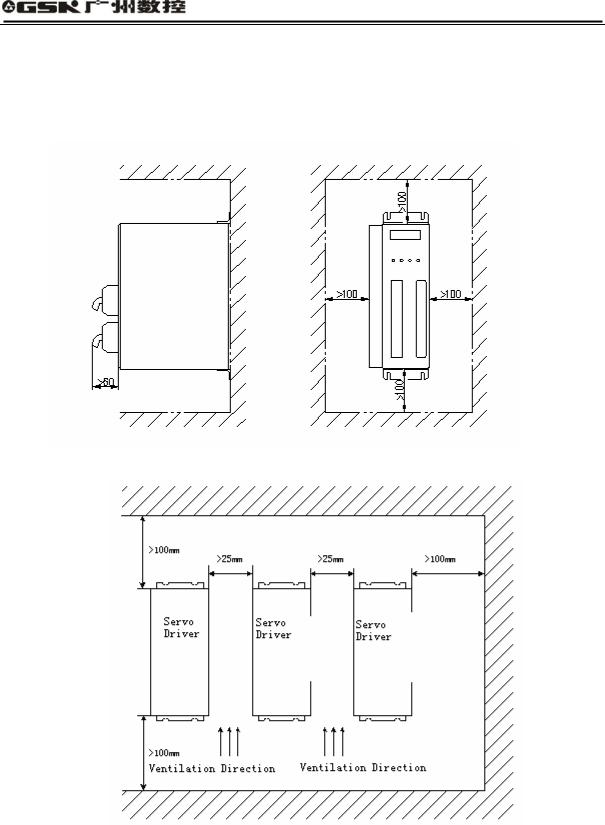
2 Installment Methods
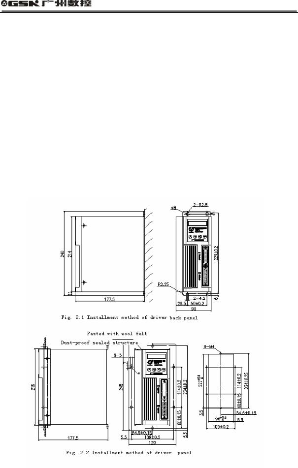
(1) Ways of Installment
The user can adopt the ways of installment by back panel or panel. The installment shall form an upward right angle with the installment plane. Fig. 2.1 is a schematic diagram for installment by back panel and Fig. 2.2 is a schematic diagram for installment by panel.
7
DA98D User Manual
(2) Installment Interval
Fig. 2.3 shows the installment interval for single drive unit and Fig. 2.4 shows the installment
interval for multiple drive units. In actual installment, the interval shall be as great as possible
to ensure good conditions for heat radiating.
Fig. 2.3 Installment for Single Drive unit
Fig. 2.4 Installment Interval for Multiple Drive units
(3) Heat Radiating
To ensure that surrounding temperature of the drive unit will not be constantly increased, there shall be convective-current wind blowing towards radiator of the drive unit within the electric cabinet.
8

DA98D User Manual
2.3 Installment of Servo Motor
 Attention
zShock on the motor shaft or encoder shall be forbidden to prevent the motor from vibration or impact.
zThe motor shall not be moved by drawing motor shaft, leading-out wire or encoder.
zLoad on the motor shaft shall not surpass its limit; otherwise, the motor may be damaged.
zThe motor must be firmly installed with anti-loosening measures.
1) Installment Environment
1 Protection
Currently, GSK SJT series and Huazhong Series of servo motor are not water resistant, so liquid must not be spattered on the motor during installment. Oil or water must be prevented from entering inside the motor through leading-out wire or the motor shaft.
Notes: if the user needs water-resistant servo motor, please make a clear
indication in the order.
2 Temperature and Humidity
The environmental temperature shall be kept between -10 and 40 . After long hours of operation, the motor will have an increasingly hot temperature, so compulsory heat radiating shall be considered when the surrounding space is relatively small or there are heating equipment.
The humidity shall not be more than 90%RH, without dew condensation.
3 Vibration
Servo motor shall not be installed at places with vibration. The vibration inflicted on the motor shall not be more than 0.5G (4.9m/s2).
2)Installment Methods
(1)Ways of Installment
Currently, SJT and ST series of motors adopt the way of installment by the flange with arbitrary installment direction.
(2)Notes:
zWhen dismantling or installing the belts and wheels, shock on the motor or motor shaft shall be forbidden to prevent the encoder from being damaged. Screw pressing tools shall be employed in the dismantlement or installment.
zCurrently, most of the SJT and ST series of motors cannot bear shaft-direction or radial-direction loads. Coupling is recommended for connecting the loads.
zWhen fastening the motor, the anti-loosening washer shall be used to prevent the motor from loosening.
9
DA98D User Manual
Chapter Three Wiring
 Warning
●Personnel involved in wiring or examination must possess sufficient abilities in this task.
●Wiring and examination must be conducted 5 minutes after the power is off for preventing electric shock.
 Attention
●The wires must be connected according to terminal voltage and electrode to prevent the equipment from being damaged or personnel from being hurt.
● The drive unit and servo motor must have good ground contact.
3.1 Standard Wiring
External connection of the drive unit is related to the control modes.
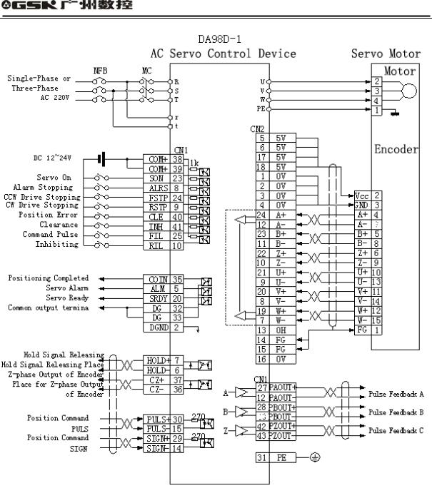
1 Position Control Mode
Fig. 3.1 shows standard wiring for the position control mode.
2 Speed Control Mode:
Fig. 3.2 shows the standard wiring for the speed control mode.
3 Wire Distributing1 Power Terminal TB
zWire cross-sectional area: Terminals of R, S, T, PE, U, V and W have an area 1.5mm2(AWG14-16) and more while terminals of r and t have an area 1.0 mm2 (AWG16-18) and more.
zGrounding: the grounding wire shall be as thick as possible. The servo driver and motor has ground contact at the point of PE terminal with a grounding resistance less than 100Ω.
zTerminal connection adopts SVM2-4 pre-insulation cold pressing terminal. The connection must be fastened.
zIt is recommended to supply power with three-phase isolating transformer, which will reduce the possibility of electric shock.
zIt is recommended that the power supply gives power through noise filter for enhancing anti-jamming ability.
zPlease install non-fuse breaker (NFB) in order to cut off external power supply when the driver breaks down.
2 CN2Contrl Signal CN1 and Feedback Signal CN2
zWire material selecting: employ shielding cable (best with inter-twisted shielding cable), the cross-section area of the core shall be 0.12mm2(AWG24-26) and more. The shielding layer shall be connected with FG terminal.
zWire and cable length: wire and cable shall be as short as possible; control signal CN1 shall not be longer than 3 meters while the feedback signal CN2 cable shall not be longer than 20 meters.
zWire laying: Wire shall be laid far away from the power circuit to prevent jamming.
10

DA98D User Manual
zPlease install surge absorbing elements in sensible elements (loop) in related circuits: DC loop is reversely connected in parallel with continuous current diode while AC loop is connected in parallel with capacitance-resistance absorbing return circuit.
 Attention
U, V and W shall be connected with motor winding in the way of one-to-one correspondence. Reverse connecting shall be forbidden.
The wires and leads shall be fastened firmly and avoid approaching radiator of the drive unit and the motor for the fear that the insulation performance will be reduced due to heat.
There will remain large quantities of electrolyzed capacitance in the servo drive unit, so there will a high remaining voltage even after the power is cut off. Do not touch drive unit or motor within 5 minutes after the power is off!
11
DA98D User Manual
Receiver AM26LS32
Fig. 3.1 Standard Wiring for Position Control Mode
12
17

DA98D User Manual
Receiver AM26LS32
Fig. 3.2 Standard Wiring for Speed Control Mode
13
 Loading...