


 This user manual describes all items concerning the operation of the system in detail as much as possible. However, it is impractical to give particular descriptions of all unnecessary and/or unavailable operations of the system due to the manual content limit, product specific operations and other causes. Therefore, the operations not specified herein shall be considered impossible or unallowable.
 This user manual is the property of GSK CNC Equipment Co., Ltd. All rights are reserved. It is against the law for any organization or individual to publish or reprint this manual without the express written permission of GSK and the latter reserves the right to ascertain their legal liability.

GSK928TEa Turning CNC System User Manual
Foreword
Dear user,
We are really grateful for your patronage and purchase of this GSK928TEa Turning CNC system made by GSK CNC Equipment Co., Ltd.
The manual describes the relative content and notes of the system.
Warning
This system can only be operated by authorized and qualified personnel as improper operations may cause accidents. Please carefully read this user manual before use!
Notes before operating the system:
zConnect the emergency stop button of the system firmly and correctly, otherwise an emergency stop alarm will occur when the system is switched on, so that the system cannot work properly( it is not the system failure).
zSet the program reference point of the system according to the actual mounting position of the tool of the machine that the system controls.
Note: The power supply of the system installed in the cabinet is exclusive to GSK’ CNC systems.
Must not take the power supply as other uses, otherwise, there maybe cause great accidence!
Chinese version of all technical documents in Chinese and English languages is regarded as final.
All specifications and designs are subject to change without notice.
All rights reserved.
We are full of heartfelt gratitude to you for supporting us in the use of GSK’s products.
II

Suggestions for safety
Suggestions for Safety
The user must carefully read the suggestions for the system before installing and operating the system.
The user must follow the suggestions of the system to ensure that the person is not hurt and the equipments are not damaged.
The user must follow the related suggestions for safety described in the user manual, and must not operate it until the manual is read completely.
The user must follow the suggestions of safety described in the user manual from the machine manufacture.
The user can operate the machine or compile the program to control the machine after completely reading the manual and the one from the machine manufacturer.
III

GSK928TEa Turning CNC System User Manual
. Graphic symbol
Caution Operation against the instructions may cause the operator serious injuries.
Alarm Wrong operation may injure the operator and damage the system.
Warning Improper operation may result in damage to the machine, as well its products.
Important information.
IV

Suggestions for safety
. Notes
1 Check before acceptance
Warning ● The damaged or defect product must not be used.
2 Delivery and storage
Warning ●Moistureproof measures are needed while the system is delivered and stored. Never climb the packing box, neither stand on it, nor place heavy items on it. Do not put over five packing boxes in piles. Take particular care of the front panel and the display of the system.
3 Installation
 Warning ●Protect the system from sunlight and raindrops. The shell of the system is not waterproof.
 Warning ●Prevent dust, corrosive air, liquid, conductors and inflammable substances from entering the system.
●Keep the system away from inflammable and explosive substances. Avoid places where there is powerful electromagnetic interference.
●Install the system firmly without vibration.
4 Wiring
 Caution ●Only qualified persons can connect the system or check the connection. The connecting wires cannot be damaged. Do not press or open the cover of the system with power on.
 Caution ●The voltage and the polarity of connecting plugs must accord with the user manual.
●Wet hands are dangerous to grasp the plug or the switch.
 Warning ●The connection must be proper and firm. ●The system must be earthed.
V

GSK928TEa Turning CNC System User Manual
5 Debugging
 Warning ●Make sure that the parameters of the system is correct before the system runs. ●No parameter is beyond the setting limit in the manual.
6 Operation
 Caution ●Only qualified operators can operate the system.
●Ensure the switch is OFF before connecting the power supply.
 Warning ●The operator can not leave the system to work alone.
●Do not switch on the system until making sure the connection is correct.
●The emergency stop button is able to disconnect all power supplies when the system breaks down. Do not switch on/off the system frequently
 Warning ●Prevent the system from the environmental interference.
7 Troubleshooting
 Caution ●Unqualified persons cannot repair the system.
 Warning ●After alarms, do not restart the system until the breakdown is fixed.
VI

Suggestions for safety
. Safety suggestions for programming
1 Setting a coordinate system
Incorrect coordinate system may cause the machine not to work as expected even if the program is correct, which may injure the operator, and damage the machine as well as its tool and workpiece.
2 Rapid traverse (positioning)
When G00 rapid traverse performs the positioning( nonlinear motion to position between its starting point and end point), make sure that the path for the tool is safe before programming. The positioning is to perform the rapid traverse, and when the tool and the workpiece are interfered, the tool, the machine and the workpiece may be damaged, and even the operator injured.
3 Applicability of user manual
The manual introduces in detail all functions of the system, including optional functions and max. controllable ranges, which are subject to change with the machine. If there is any doubt, please read the instruction for the machine.
4 Functions of CNC system and machine
CNC machines depend on CNC systems, but also power voltage cabinets, servo systems, CNC and the operator panels. It is hard to explain all the integrated functions, programming and operation. Do not use integrated instructions not included in the manual until they have been tested successfully.
VII

GSK928TEa Turning CNC System User Manual
. Notes and Safety Suggestions for Operating Machine
1 Test the machine without workpieces or tools. Make sure that the machine runs well before it starts to work.
2 Check the input data of the system carefully before operating the machine. Incorrect input data may cause the machine to work improperly, so as to damage the workpiece and the tool, as well injure the operator.
3 Make sure that the input feedrate of the system is suitable for the expected operation. Feedrate has a maximum for each machine, and the amount of the feed rate is subject to change with operation. Choose the maximum according to the instructions of the machine. Improper feedrate leads the machine to work wrongly, so as to damage the workpiece and the tool, as well injure the operator.
4 When offset is needed, check the direction and the amount of the compensation. Improper compensation causes the machine to work wrongly, so as to damage the workpiece and the tool, as well injure the operator.
5 If the machine is to run in JOG working mode, check the current position of the tool and the workpiece, and correctly specify the moving axis, moving direction and the feedrate. MPG(Handwheel) control with great override, such as 100, may damage the machine and its tool, even injure the operator.
6 If the tool is return to the reference point, make sure that the machine has been equipped with the device to detect the reference point, otherwise, the tool can not reach the reference point, which may damage the machine and its tool, and even injure the operator.
VIII

Suggestions for safety
Safety Responsibility
Safety responsibility for manufacturer
——The manufacturer should be responsible for danger from clearing out or controlling design and/or structure of the CNC system and its supplied accessories.
——The manufacture should be responsible for safety of the CNC system and its supplied accessories.
——The manufacture should provide the user for use information and suggestion.
Safety responsibility for user
——The user should learn and master the safety operation content by studying and training the CNC system safety operation.
——The user should be responsible for own adding, changing, or modifying the previous
CNC system and accessories.
——The user should be responsible for the danger caused by the operation, regulation, maintenance, installation and storage and delivery which are not performed according to the user manual.
IX

GSK928TEa Turning CNC System User Manual
X
Contents
CONTENTS
OPERATION·································································································································1
CHAPTER ONE OVERVIEW ··························································································································· 1
CHAPTER TWO TECHNICAL SPECIFICATIONS····························································································· 3
2.1Technical specifications····················································································································· 3
2.2Functional difference between 928TEa and 928TCa turning CNC system·································· 4 CHAPTER THREE OPERATION PANEL·········································································································· 6
3.1LCD Display······································································································································· 6
3.2LED Status Indicator ························································································································ 6
3.3Keyboard············································································································································ 6
3.3.1Character keys···························································································································· 6
3.3.2Working mode selection key······································································································ 7
3.3.3Function keys······························································································································ 7
3.3.4Cycle start and cycle pause (feed hold)key··············································································· 8
3.3.5Manual axis control key············································································································· 8
3.3.6Manual auxiliary function key ·································································································· 9
3.3.7Edit keys···································································································································· 10 CHAPTER FOUR SYSTEM OPERATION ········································································································11
4.1System ON/OFF, Initial State, Modal, and Safe Protection··························································11
4.1.1Power on·····································································································································11
4.1.2Power off ····································································································································11
4.1.3System, program initial and modal························································································· 12
4.1.3.1Initial and modal ··············································································································· 12
4.1.3.2Initial mode and modal of program················································································· 12
4.1.4Safe protection ·························································································································· 13
4.1.4.1Hardware limit protection ································································································ 13
4.1.4.2Software limit safe protection··························································································· 14
4.1.4.3Emergency stop alarm(emergently stopping the system) ·············································· 15
4.1.4.4Drive unit alarm ················································································································ 16
4.1.4.5Other alarms······················································································································ 16
4.1.4.6Switching off power supply······························································································· 16
4.1.4.7Reset operation ·················································································································· 17
4.2CNC Working Mode Selection ······································································································· 17
4.3EDIT Working Mode ······················································································································ 17
4.3.1Part program catalog search ··································································································· 18
4.3.2Selecting, creating, deleting, renaming and copying a part program ·································· 19
4.3.2.1Selecting and creating a part program ············································································ 19
4.3.2.2Delete a part program······································································································· 20
4.3.2.3Deleting all part programs································································································ 20
4.3.2.4Renaming a part program ································································································ 21
4.3.2.5Copying a part program ··································································································· 21
4.3.3Part program communication································································································· 21
4.3.3.1Sending part programs CNC→PC, CNC→USB, CNC→CNC ······························ 22
4.3.3.2Receiving part programs PC→CNC, USB→CNC, CNC→CNC ··························· 22
4.3.3.3TXT part program standard format in PC····································································· 23
4.3.4Part program content input and edit······················································································ 24
4.3.4.1Inputting program content ······························································································· 27
4.3.4.2Inserting program line ······································································································ 27
4.3.4.3Deleting a block ················································································································· 28
4.3.4.4Inserting a character in a block························································································ 28
4.3.4.5Deleting a character in a block························································································· 28
4.3.4.6Modifying a block content ································································································ 28
4.3.4.7Inserting a macro character string ·················································································· 29
4.3.4.8Program stored space········································································································ 29
4.3.4.9No. 253 program operation······························································································· 29
4.3.4.10No. 254 program operation····························································································· 30
4.3.5hp5 function ······························································································································ 30
XI

GSK928TEa Turning CNC System User Manual
4.3.5.1Part program command help····························································································30
4.3.5.2Relative parameter help for arc························································································30
4.3.5.3Line number sort ···············································································································31
4.3.5.4Replacing character string································································································31
4.3.5.5Cursor position···················································································································32
4.3.5.6MPG controlling cursor moving·······················································································32
4.3.6Part program compiling···········································································································32
4.3.6.1hp3 compiling command ···································································································32
4.3.6.2hp3 analog drawing ···········································································································33
4.3.6.3Program compiling result analysis ···················································································34
4.3.6.4Program compound check prompt···················································································35
4.4JOG Working Mode ························································································································36
4.4.1Coordinate axis movement·······································································································38
4.4.1.1JOG movement···················································································································38
4.4.1.2Step movement ···················································································································39
4.4.1.3MPG control·······················································································································39
4.4.1.4Rapid traverse speed selection··························································································40
4.4.1.5Low speed feed speed selection ·························································································41
4.4.1.6Inputting field moving, setting feedrate···········································································41
4.4.1.7Drive unit enabling control ·······························································································43
4.4.1.8Coordinate axis motion alarm prompt·············································································43
4.4.2Creating coordinate system······································································································44
4.4.2.1Creating machine coordinate system_machine zero return(machine reference point return)················································································································································44
4.4.2.2Creating machine coordinate system_without machine zero(no machine reference point)··················································································································································46
4.4.2.3Setting workpiece coordinate system ···············································································46
4.4.2.4Setting program reference point·······················································································47
4.4.2.5Program reference point return ·······················································································48
4.4.2.6Recovering the workpiece coordinate system and program reference point················48
4.4.3Spindle control function ···········································································································49
4.4.3.1Spindle starting/stopping control ·····················································································49
4.4.3.2Spindle S command _gear shifting control ······································································50
4.4.3.3Spindle S_ speed control····································································································51
4.4.3.4Setting spindle working state····························································································54
4.4.4Cooling control··························································································································54
4.4.5Manual tool change control ·····································································································55
4.4.6Manual toolsetting operation···································································································57
4.4.7Hydraulic chuck control function····························································································60
4.4.8Hydraulic tailstock control function ·······················································································62
4.4.9Other option functions··············································································································64
4.4.9.1Three-color indicator control····························································································64
4.4.9.2Lubricating control············································································································65
4.4.9.3Machine electricity delay power-on control·····································································65
4.4.9.4External MPG operation···································································································66
4.4.9.5Safety door check function································································································66
4.4.9.6Pressure low alarm check function···················································································67
4.4.10Searching run message in JOG working mode ····································································67
4.4.11Appendix: ····························································································································67
4.4.11.1MDI input controlling M command table MDI·····························································67
4.4.12Spindle turn function··············································································································68
4.5AUTO Working Mode·····················································································································68
4.5.1System working mode in AUTO working mode·····································································70
4.5.2Function key operation in AUTO working mode···································································70
4.5.2.1SINGLE execution and CONTINUOUS execution switch·············································70
4.5.2.2Dry run and machining run switch ··················································································70
4.5.2.3Switch between coordinate system and graph display····················································71
4.5.2.4Running a part program from the first block ·································································71
4.5.2.5Running a part program from a specified block·····························································72
4.5.3Displaying in a part program running····················································································72
XII

Contents
4.5.3.1Graphic display data definition························································································ 73
4.5.3.2Inputting data of graph display························································································ 74
4.5.3.3Machining workpiece count and timing ·········································································· 75
4.5.4Manual operation of miscellaneous function ········································································· 75
4.5.5Speed override tune in AUTO working mode········································································ 76
4.5.5.1Speed override tune··········································································································· 76
4.5.5.2MPG speed control ············································································································ 76
4.5.6Interference operation in program execution process··························································· 77
4.5.6.1Press key interference in program execution·································································· 77
4.5.6.2External feed hold knob···································································································· 78
4.5.6.3External start and pause signal························································································ 79
4.5.6.4Feed device alarm function······························································································· 80
4.5.7Modifying offset in program run ···························································································· 80
4.5.7.1Modifying offset method in program run········································································ 80
4.5.7.2Modifying tool compensation validity in program running··········································· 81
4.5.8Searching run message in AUTO working mode··································································· 81
4.5.9Program reference point return in AUTO working mode ···················································· 82
4.5.10System reset and emergence stop signal processing in AUTO working mode ·················· 83
4.5.11Regulating LCD brightness in AUTO, JOG working mode ··············································· 83
4.6Parameter Working Mode·············································································································· 84
4.6.1Parameter overview·················································································································· 84
4.6.1.1Parameter privilege··········································································································· 85
4.6.1.2Entering operation level···································································································· 85
4.6.1.3Parameter management···································································································· 85
4.6.2Parameter modification ··········································································································· 87
4.6.2.1Parameter search··············································································································· 87
4.6.2.2Parameter modification ···································································································· 87
4.6.3Parameter hp6 function ··········································································································· 88
4.6.3.1Parameter communication and standard format ··························································· 88
4.6.3.2Parameter draw and solidifying······················································································· 91
4.6.3.3System software upgrade and memory update······························································· 92
4.6.3.4Functional command privilege························································································· 93
4.6.4Parameter explanation············································································································· 93
4.6.4.1Reference point, software limit parameter bit parameter __ P000 P020··················· 93
4.6.4.2 |
Parameters related to zero return function |
__ P021 P026, P109 P111, P406 |
P407 ··················································································································································· 94 |
||
4.6.4.3 |
Traverse speed, acceleration time parameter |
__P100 P108, P112 P118 ·············· 96 |
4.6.4.4 |
Parameters related to transmission and compensation __ P200 P209, P411, |
|
P1000 P1905··································································································································· 97
4.6.4.5Parameters related to spindle, cooling __ P300 P317, P326, P329, P410··················· 99
4.6.4.6 Parameters related to tool post __ P318 P325, P408 ·············································· 102
4.6.4.7Parameters related to chuck tailstock __ P327 P328, P409 ······································ 104
4.6.4.8Run and efficiency bit parameter __ P400 P401························································ 105
4.6.4.9Relationship between path and run, efficiency parameter ·········································· 107
4.6.4.10Safety and debugging bit parameter __ P402 P404················································· 108
4.6.4.11Motor drive bit parameter __ P405···············································································112
4.6.4.12 Parameters related to other interfaces __ P412, P330 P332 ·································113
4.6.4.13Miscellaneous parameter __ P413 P416, P333··························································114
4.6.4.14Interface parameter __P500 P556··············································································116
4.6.4.15Variable initial value __P600 P639·············································································116
4.6.4.16Related parameter of G76 __P336 P339····································································117
4.6.5Appendix: parameter list········································································································117
4.6.5.1Reference parameter list··································································································117
4.6.5.2Motion parameter list·······································································································118
4.6.5.3Transmission parameter list ····························································································118
4.6.5.4Miscellaneous parameter list···························································································119
4.6.5.5Bit parameter····················································································································119
4.6.5.6Variable initial value list ································································································· 120
XIII

GSK928TEa Turning CNC System User Manual
4.6.5.7Pitch compensation parameter list·················································································120
4.6.5.8Interface parameter list···································································································121
4.6.5.9Parameter list related to command forbidden ······························································122
4.6.5.10Parameter list related to input interface release ·························································122
4.6.5.11Parameter list related to output interface release ·······················································123
4.7OFFSET Working Mode ···············································································································124
4.7.1Tool offset value search···········································································································125
4.7.2Input tool offset data by keyboard key ·················································································125
4.7.3Offset value in each group clear ····························································································126
4.7.4Tool offset hp6 function··········································································································126
4.7.4.1Communication and standard format of tool offset data·············································126
4.7.4.2Offset data clear···············································································································127
4.8Diagnosis Working Mode ··············································································································128
4.8.1Interface signal search············································································································128
4.8.2Interface signal name display explanations··········································································128
4.8.3Input interface diagnosis explanation···················································································129
4.8.4Output interface diagnosis explanation ················································································129
4.8.5Output interface operation function ·····················································································129
4.8.6Spindle encoder and spindle speed check ·············································································130
4.8.7Diagnosis hp6 function ···········································································································130
4.8.8Machine miscellaneous function control···············································································130
CHAPTER FIVE RS232 AND USB SYSTEM COMMUNICATION ·································································132
5.1RS232 Communication··················································································································132
5.1.1Communication between CNC and PC·················································································132
5.1.2Communication between CNC and CNC ·············································································133
5.2USB Communication·····················································································································133
5.2.1USB operation·························································································································133
5.2.2USB file catalog requirements ·······························································································134
PROGRAMMING ···················································································································· 135
CHAPTER ONE PROGRAMMING FUNDAMENTAL ·····················································································135
1.1Coordinate Axis and its Direction ································································································135
1.2Machine Coordinate System, Machine Zero ···············································································136
1.3Program Reference Point··············································································································136
1.4Machine 2nd, 3rd Program Reference Point···············································································136
1.5Workpiece Coordinate System ·····································································································136
1.6Programming Coordinate ·············································································································137
1.6.1Absolute Coordinate Values···································································································137
1.6.2Incremental (Relative)Coordinate Values·············································································137
1.6.3Compound Coordinate Values·······························································································138
1.7Diameter Programming and Radius Programming ···································································138
1.8Interpolation Function ··················································································································138
CHAPTER TWO PROGRAM STRUCTURE···································································································140
2.1Character········································································································································140
2.2Block ···············································································································································140
2.3Block Number ································································································································141
2.4Block ···············································································································································141
2.5Block Skip Symbol and Comment································································································142
2.6Program Structure·························································································································142 CHAPTER THREE MSTF COMMANDS AND FUNCTIONS ··········································································144
3.1M — Miscellaneous Function (Command List) ··········································································144
3.1.1M00 — Pause···························································································································145
3.1.2M02 — End of Program·········································································································145
3.1.3M20 — End of Program Cycle Machine···············································································145
3.1.4 M30 — End of Program Spindle OFF Cooling OFF ·····················································146
3.1.5M03, M04, M05 —Spindle Control·······················································································146
XIV

Contents
3.1.6M08, M09 — Cooling control································································································ 146
3.1.7M10 M11, M12 — clamping/releasing workpiece, cancelling chuck output signal······· 147
3.1.8M32, M33 — Lubricating ON/OFF······················································································ 147
3.1.9M41, M42, M44, M43 — Spindle Automatic Gear Shifting Control ································· 147
3.1.10M78, M79, M80 —Tailstock going forward and retreating backward, cancelling tailstock output signal········································································································································ 148
3.1.11M96 —Cycle execution call·································································································· 148
3.1.12M97 — Program transfer ···································································································· 149
3.1.13M98, M99 — Subprogram call and subprogram return··················································· 149
3.1.14M21, M22, M23, M24 —User Output Control ·································································· 150
3.1.15M91, M92, M93, M94 — User input··················································································· 151
3.1.16M47, M48 — Setting spindle working state ······································································· 152
3.1.17M60~M74 — Customized commands················································································· 152
3.2S function — Spindle Function ···································································································· 152
3.2.1Gear shifting controlling spindle motor ··············································································· 153
3.2.2Spindle controlling conversion motor··················································································· 153
3.3T function — Tool Function·········································································································· 154
3.3.1Tool offset execution mode-moving slide ·············································································· 154
3.3.2Tool offset execution modemodifying coordinates····························································· 155
3.4F function — Feedrate Function ···························································································· 156 CHAPTER FOUR G COMMANDS AND FUNCTIONS ···················································································· 158
4.1G00 —Rapid Traverse (Positioning)···························································································· 158
4.2G01 — Linear Interpolation········································································································· 159
4.3G02, G03, G05 —Circular interpolation····················································································· 161
4.4Chamfering Function···················································································································· 165
4.4.1Linear chamfering·················································································································· 165
4.4.2Circular chamfering··············································································································· 167
4.4.3Special cases···························································································································· 168
4.4.4Chamfer supplementary explanation ··················································································· 170
4.5Thread Cutting Command ··········································································································· 170
4.5.1G33 —thread cutting·············································································································· 171
4.5.2G34 — variable pitch thread cutting ···················································································· 178
4.6G32 —Tapping Cycle ···················································································································· 180
4.7G50 — Setting a Workpiece Coordinate System ········································································ 181
4.8G51 — Recovering Workpice Coordinate System Setting························································· 182
4.9G26 — X, Z, Y Reference Point Return ······················································································ 182
4.10G28 — Return to Machine Zero(Machine Reference Point)··················································· 183
4.11G30 — 2nd, 3rd Program Reference Point Return ····································································· 184
4.12G04 — Dwell································································································································ 185
4.13G96 —Constant Surface Speed Control, G97 —Constant Surface Speed Cancel ················ 185
4.14Single Canned Cycle···················································································································· 188
4.14.1G90 —outer cylinder face turning cycle (axial cutting cycle)··········································· 188
4.14.2G92 —Thread cutting cycle································································································· 191
4.14.3G94 —Inner/outer end face (taper) turning cycle ····························································· 198
4.14.4G74 —Deep hole machining cycle on end face··································································· 200
4.14.5G75 —Grooving cycle ·········································································································· 202
4.15Compound Cycle ························································································································· 204
4.15.1G71 —axial plane roughing compound cycle····································································· 204
4.15.2G72 —End face roughing cycle··························································································· 209
4.15.3G73 — closed cutting cycle command group ····································································· 212
4.15.4G76 — multi thread cutting cycle command group ·························································· 217
4.16G22, G80 —Program Part Cycle ······························································································· 222
4.17G98 —Feed per Minute(feed/m) , G99 —Feed per Rev(feed/r) ·············································· 223
4.18G31 — Skip·································································································································· 224
4.19G52 — rotary axis coordinate clearing integer········································································· 225
4.20Additional Axis(Y) Function······································································································· 226
4.20.1Additional axis(Y) start········································································································ 226
4.20.2Additional axis(Y) realizing motion···················································································· 226
4.21Appendix: G function and its Explanation Table ····································································· 227
4.22Appendix G and its Relative Parameter Explanation ··························································· 229
XV

GSK928TEa Turning CNC System User Manual
CHAPTER FIVE TOOL NOSE RADIUS COMPENSATION (G41,G42)··························································230
5.1Application ·····································································································································230
5.1.1Overview··································································································································230
5.1.2Command format····················································································································231
5.1.3Compensation direction ·········································································································231
5.1.4Programming rules·················································································································232
5.1.5Application example ···············································································································233
5.1.6Toolsetting and tool nose number of ball tool·······································································234
5.2Tool Nose Radius Compensation Offset Path Explanation························································236
5.2.1Inner and outer side················································································································236
5.2.2Tool movement in start-up ·····································································································237
5.2.3Tool movement in OFFSET mode ·························································································238
5.2.4Tool movement in OFFSET canceling···················································································239
5.2.5Tool interference check···········································································································241
5.2.6Particulars ·······························································································································242
5.2.7Radius compensation of compound cycle command ···························································242
CHAPTER SIX PITCH ERROR COMPENSATION·························································································244
6.1Leading-Screw Error Curve ·········································································································244
6.2Constant Interval Description Method························································································245
6.3Inflection Point Description Method····························································································246
6.4Pitch Compensation Execution Method ······················································································247
CHAPTER SEVEN GENERAL PROGRAMMING RULES AND EXAMPLES ····················································250
7.1General Programming Rules ········································································································250
7.2Programming Rules for Commands in One Block ·····································································251
7.3Command Execution Sequence ····································································································252
7.4Programming Example ·················································································································254
7.4.1Outer machining example······································································································254
7.4.2Thread machining example····································································································255
7.4.3Compound machining example ·····························································································257
CHAPTER EIGHT ALARM MESSAGE·········································································································262
8.1Emergency Alarm ··························································································································262
8.2Alarm Table in PARAMETER, OFFSET Working Mode(i.e.E001~E009)·····························262
8.3General Chart of Alarm in Working Mode i.e. E100~ E199 ···············································264
8.4Emergency Alarm Program Alarm Table i.e.E200~ E299, E600~ E699 ····························266
8.4.1Alarm in program command(i.e. E200~299)·······································································266
8.4.2Alarm in program command (i.e. E600~699)·······································································269
8.5Alarm Table in JOG OR AUTO Working Mode i.e.E300~ E499 ···································270
8.5.1Alarm in Executing Relative Operations (i.e E300~E399)·················································271
8.5.2Relative alarm in executing statement i.e.E400~ E499 ·················································274
CHAPTER NINE STATEMENT PROGRAMMING··························································································276
9.1Variable···········································································································································276
9.1.1Variable expression method ···································································································276
9.1.2Classification of variable········································································································276
9.1.2.1Command variable ··········································································································276
9.1.2.2Pointer variable················································································································278
9.1.2.3Interface variable·············································································································279
9.1.2.4Keyboard scan register R5001························································································281
9.1.2.5Display window register r5002························································································282
9.1.2.6r5003 display value register r5003··················································································284
9.1.2.7Graph update register r5004···························································································285
9.1.2.8Program control register r5008 ······················································································285
9.1.2.9System special variable set 1···························································································286
9.1.2.10System special variable set 2·························································································286
9.2Statement ········································································································································287
9.2.1Assignment statement·········································································································287
9.2.2Conditional statement·········································································································288
9.2.3Statement program example······························································································289
9.3Process Monitoring and Execution·······························································································290
9.3.1Process monitor description (r7000) ·················································································291
XVI

Contents
9.3.2The start and close of process monitor ············································································· 292
9.3.3Monitor program example································································································· 294
9.3.4Pulse monitoring (r7100) ··································································································· 295
9.3.5Pulse monitoring program example·················································································· 296
9.3.6Variable transfer register (r7900)······················································································ 297
9.4Attached List·································································································································· 298
9.4.1ASCII list····························································································································· 298
9.4.2Often used color and code value corresponding list ························································ 298 CHAPTER TEN CUSTOMIZATION COMMAND PROGRAM ········································································ 299
10.1Customization Command ··········································································································· 299
10.1.1Customization command program format········································································· 299
10.2Customization Command Store P254 ··············································································· 300
10.2.1Format and debugging of customization command storeroom········································ 300
10.2.2Explanation of customized command storage···································································· 301
10.2.3Customized command machining example········································································ 301
CONNECTION ·························································································································305
CHAPTER ONE INTERFACE······················································································································· 305
1.1Rear Cover Interface Position Layout························································································· 305
1.2Total Frame···································································································································· 306 CHAPTER TWO INTERFACE GRAPH ········································································································· 307 CHAPTER THREE CNC DEVICE CONNECTION························································································ 309
3.1Front Cover Communication Interface······················································································· 309
3.1.1USB interface·························································································································· 309
3.1.2Serial RS232 technical specifications···················································································· 309
3.1.3Serial RS232 signal definition ······························································································· 310
3.1.4Connecting with external PC by RS232 ··············································································· 310
3.1.5Connecting with another CNC system by RS232 communication interface (communication connections between GSK928TEa) ······································································ 310
3.2X1,X2 Interface·······························································································································311
3.2.1X1 interface signal definition··································································································311
3.2.2X2 interface signal definition································································································· 313
3.2.4Connection method of output signal····················································································· 316
3.2.5Input/output signal technical specification ·········································································· 317
3.3Machine Zero Return Function and Connection········································································ 317
3.4Tool Exchange Control Function and Connection······································································ 319
3.4.1Tool exchange control signal definition ················································································ 319
3.4.2Signal connection···················································································································· 320
3.4.3Function description··············································································································· 320
3.4.3.1Tool change mode 0 ········································································································· 320
3.4.3.2Tool change mode 1 ········································································································· 320
3.4.3.3Tool change mode 2 ········································································································· 321
3.4.3.4Tool change mode 3 ········································································································· 322
3.4.3.5Tool change mode 4 ········································································································· 323
3.4.3.6Tool change 9···················································································································· 324
3.4.4Tool signal check and parameter setting ·············································································· 326
3.4.4.1Default mode (P408_d7=0) ····························································································· 326
3.4.4.2 Table look-up mode (P408_d7=1)················································································ 327
3.5X3 Motor Interface························································································································ 328
3.5.1Signal definition······················································································································ 328
3.5.2Technical specifications·········································································································· 328
3.5.3Equivalent circuit ··················································································································· 328
3.5.3.1 Drive unit alarm signal XALM, ZALM, YALM························································ 328
3.5.3.2Enabling signal XEN,ZEN····························································································· 329
3.5.3.3Pulse signal and direction signal ···················································································· 329
3.5.4Connection between CNC system and drive unit of compound stepper motor ················ 330
XVII

GSK928TEa Turning CNC System User Manual
3.5.5Connecting between CNC and drive unit of reaction stepper motor ·································332
3.5.6Connection layout between CNC and AC servo drive unit·················································334
3.5.7Connection layout between CNC and Panasonic drive unit ···············································336
3.5.8Connection layout between CNC system and Japanese Yaskawa drive unit·····················337
3.6X4 Spindle Interface······················································································································338
3.6.1Signal definitions·····················································································································338
3.6.2Converter technical specification ··························································································338
3.6.3Encoder technical specifications····························································································338
3.6.4Connection layout of converter analog voltage ····································································339
3.6.5Encoder interface method······································································································339
3.6.6Encode interface connection layout·······················································································339
3.6.7Connection between CNC system Y and AC servo drive unit ············································340
3.6.8Connection between CNC system Y and DAP03 spindle drive unit···································341
3.7X5 MPG Interface··························································································································342
3.7.1Signal definition ······················································································································342
3.7.2Interface method·····················································································································342
3.7.3Connection layout ···················································································································342
CHAPTER 4 USER USE AND MAINTENANCE ·····························································································343
4.1Environmental Condition··············································································································343
4.2Earthing··········································································································································343
4.3Power Supply Requirements·········································································································343
4.4Guard··············································································································································343
4.5Use after Long-Time Unuse ··········································································································343
APPENDIX·····················································································································································344
APPENDIX 1 CNC SYSTEM ELECTRICAL COMPONENT SYMBOL EXPLANATIONS····································344
APPENDIX 2 CNC SYSTEM TOOL POST CONTROLLER CIRCUIT METHOD LAYOUT ·································345
APPENDIX 3 INTERFACE CIRCUIT METHOD LAYOUT ···············································································346
APPENDIX 4 EXTERNAL CONTROL CONNECTION LAYOUT ······································································349
APPENDIX 5 CNC SYSTEM APPEARANCE INSTALLATION DIMENSION·····················································350
XVIII
Operation |
Chapter One Overview |
Operation
Chapter One Overview
With 480×234 lattice TFT color graphic LCD, GSK 928TEa CNC system takes as key control the high-speed CPU and the complex programmable logic device of super-large-scale integrated circuit CPLD. ISO CNC code is used to write part programs. The system is characterized by a full screen editing, Chinese operation interface, real time demonstration of the machining process, simple operation. the system can be matched with stepper motors or AC servo drive unit to machine outer cylinders, end faces, grooves, tapers, circular arcs and threads with high cost-performance.
Technical Specifications:
9X, Z link to realize the short linear high-speed smooth interpolation, 0.001mm interpolation precision, max. rapid traverse speed 30m/min
9Optional to Y(set by the parameter), Y not only realizes the rapid traverse,
feed(JOG/STEP/MPG feed) motion, alone tapping motion, but also sets the coordinate system, program zero return, manual machine zero return and other operations
9Control servo spindle
9Flexible and convenient programming with statement programming function
9USB interface communication to get the convenient and fast operation
9Least command unit 0.001mm, command electronic gear ratio 1 99999 / 1 99999
9Control all kinds of automatic tool post, spindle automatic shifting gear
9Pitch error compensation, backlash compensation, tool length compensation, tool radius C compensation function
9Exponential acceleration/deceleration control used to high-speed, high precise machining
9Automatic chamfering function
9Tapping function
9Course monitoring function
9Cutting metric/inch thread, end face thread, variable pitch thread, continuous thread; thread high-speed run-out
9Full editing part programs, storing 255 machining programs; No. 253 program up to 4MB
9Big screen color LCD, color configuration is selected by the parameter
9MSTE state real-time display in machining
9Multi-level operation password to conveniently manage devices
9Parameter backup function
9Parameter, offset data communication function
9Bilateral communication between CNC and CNC, between CNC and PC, serial upgrade CNC software
1

GSK928TEa Turning CNC System User Manual
9Bilateral communication between CNC and USB, CNC is upgraded by USB
9Installation dimension, electric characteristics, some interfaces are compatible to GSK928TEa Turning CNC System
2

Operation |
Chapter Two Technical Specifications |
Chapter Two |
Technical Specifications |
2.1 Technical specifications |
|
Motion control
G command
Thread machining
Precision compensation
M command
T command
Spindle speed control
I/O function
Statement programming
Display window
Program edit
Communication
Optional drive unit
Controlled axes: X, Y, Z; simultaneous controlled axes(interpolation axes): 2 (X, Z) Interpolation: X, Z linear, arc interpolation Z/Y or X/Y linear interpolation
Position command range:-9999.999 mm 9999.999mm least command unit: 0.001mm Command multiplex coefficient 1 99999 command division coefficient 1 99999
Rapid traverse speed up to 30000mm/min rapid override F25%, 50%, 75%, 100% real-time regulation
Cutting federate: up to 15000mm/min federate override 0 150% 16 grades real-time regulation MANUAL federate: 0mm/min 1260mm/min 16-grade real-time regulation or it is defined extemporarily MPG feed 0.001mm, 0.01mm, 0.1mm
Acceleration/deceleration: cutting feed can select exponential/linear acceleration/deceleration
32 commands G00, G01, G02, G03, G04, G05, G26, G28, G30, G31, G32, G33, G34, G40, G41, G42, G50, G51, G71, G72, G73, G74, G75, G76, G90, G92, G94, G96, G97, G98, G99
Tapping: metric/inch single/multiple straight thread, taper thread, end face thread; variable pitch thread; thread run out length, angle and speed can be set, executing the high-speed thread run-out; pitch: 0.001mm 500mm or 0.06tooth/inch 25400tooth/inch; tapping function
Spindle encoder: lines can be set (100p/r 5000p/r); Drive ratio between encoder and spindle is 1:1 Backlash compensation: 0 mm 10.000mm
Pitch error compensation: 300 compensation points for each axis; use constant distance or inflection point to create data; the system executes the delicate linear compensation
Offset: 16 tool selections, 64 groups tool length compensation and tool nose radius compensation (offset C)
Toolsetting method: fixed-point, trial cutting
Offset executing method: traversing tool or modifying coordinate offset
M00, M02, M20, M30, M03, M04, M05, M08, M09, M10, M11, M12, M32, M33, M41, M42, M43, M44, M47, M48, M78, M79, M80, M96, M97, M98, M99, M91, M92, M93, M94, M21, M22, M23, M24 M commands are defined by operator: M60 M74 realize the special function control
Up to 16 tools T01□□ T16□□ setting tool post type, parameters to select too change course Tool post type is set to 0 when the line-up tool is used
Speed switching value control: S 4-gear directly controlling output range is S01 S04; or 16-gear BCD output range is S00 S15
Speed analog voltage control: S specifies the spindle speed per minute or the cutting surface speed (constant surface speed) , outputs 0 10V voltage to spindle converter, supports 4-gear spindle speed M41 M44 with stepless shifting gear
Support DAP03 servo spindle speed/position control mode switch, realize spindle, Z or X link function
I/O function diagnosis display
I/O interface 23 input/18 output interfaces
Assignment statement: complete assignment, many arithmetic and logic operations Conditional statement: complete conditional judgement and skip
Display: 480×234 lattice, color LCD LED or CCFL light in poor
Display method: Chinese or English window set by a parameter, displaying machining path of workpiece in real-time
Program capacity: max. 255 programs, No. 0 252, 254 with 800KB, No.253 with 4MB FLASH
Edit method: edit in full screen, relative/absolute coordinate and compound program call, subprogram multi-level embedding
Program drawing check
USB, RS232 interface bidirectionally transmitting programs, parameters and offset between CNC and USB, CNC and PC, CNC and CNC
Supporting software RS232, USB to download and upgrade

 DA98 Series Digital AC Servo or DY3 Series Stepper Drive unit with pulse + direction signal input
3

GSK928TEa Turning CNC System User Manual
2.2Functional difference between 928TEa and 928TCa turning CNC system
The manual is applied to two types of system: 928TEa, 928TCa. Functions of 928TCa turning CNC system are less than those of 928TEa as follows:
|
Functional |
|
|
|
|
|
|
928TEa |
|
|
|
|
|
928TCa |
|
|
Remark |
|
|
|
difference item |
|
|
|
|
|
|
|
|
|
|
|
|
|
|
||||
|
|
|
|
|
|
|
|
|
|
|
|
|
|
|
|
|
|
|
|
|
|
|
|
|
|
|
|
|
|
|
|
|
|
|
|
|
|
|
|
|
Controllable axis |
|
|
|
|
|
X, Y, Z |
|
|
|
|
|
X, Z |
|
|
|
|||
|
|
|
|
|
|
|
|
|
|
|
|
|
|
|
|
|
|
|
|
|
Rapid traverse |
|
|
|
Max. 30000 mm /min |
|
|
|
Max. 15000 mm /min |
|
|
|
|||||||
|
speed |
|
|
|
|
|
|
|
|
|
|||||||||
|
|
|
|
|
|
|
|
|
|
|
|
|
|
|
|
|
|
||
|
|
|
|
|
|
|
|
|
|
|
|
|
|||||||
|
Cutting speed |
|
|
|
0.001 15000 mm/min |
|
|
|
0.001 4000 mm/min |
|
|
|
|||||||
|
|
|
|
|
|
|
|
|
|
|
|
|
|||||||
|
Max. radius of arc |
|
|
|
|
Max. machining: 1000m |
|
|
|
Max. machining: 100m |
|
|
|
|
|||||
|
|
|
|
|
|
|
|
|
|
|
|||||||||
|
Tool nose radius |
|
C tool radius compensation, PROGRAMMING, |
|
No the function |
|
|
|
|||||||||||
|
compensation |
|
Chapter 5 Tool Nose Radius Compensation |
|
|
|
|
||||||||||||
|
|
|
|
|
|
|
|
||||||||||||
|
|
|
|
|
|
|
|
|
|
|
|
|
|
|
|
||||
|
Pitch error |
|
Fine |
linear |
pitch |
error |
|
compensation, |
|
|
|
|
|
|
|||||
|
|
PROGRAMMING, |
Chapter |
6 |
Pitch |
Error |
|
No the function |
|
|
|
||||||||
|
compensation |
|
|
|
|
|
|||||||||||||
|
|
Compensation |
|
|
|
|
|
|
|
|
|
|
|
|
|
||||
|
|
|
|
|
|
|
|
|
|
|
|
|
|
|
|
|
|||
|
|
|
|
|
|
|
|
|
|
|
|
|
|||||||
|
Automatic chamfer |
|
|
Automatic chamfer |
function, |
PROGRAMMING, |
|
|
No the function |
|
|
|
|
||||||
|
function |
|
|
Chapter 4.4 Chamfer Function |
|
|
|
|
|
|
|
|
|||||||
|
|
|
|
|
|
|
|
|
|
|
|
||||||||
|
|
|
|
|
|
|
|
|
|
|
|
|
|
|
|
|
|
|
|
|
Variable pitch |
|
Variable |
pitch thread G34, |
PROGRAMMING, |
|
|
|
|
|
|
||||||||
|
|
Chapter |
4.5.2 |
G34-Variable |
Pitch |
Thread |
|
No the function |
|
|
|
||||||||
|
thread |
|
|
|
|
|
|||||||||||||
|
|
Cutting |
|
|
|
|
|
|
|
|
|
|
|
|
|
|
|||
|
|
|
|
|
|
|
|
|
|
|
|
|
|
|
|
|
|
||
|
|
|
|
|
|
|
|
|
|
|
|
|
|
|
|
|
|
|
|
|
Thread repair |
|
|
|
Thread repair function |
|
|
|
No the function |
|
|
|
|||||||
|
function |
|
|
|
|
|
|
|
|
|
|||||||||
|
|
|
|
|
|
|
|
|
|
|
|
|
|
|
|
|
|
||
|
|
|
|
|
|
|
|
|
|
||||||||||
|
Manual tapping |
|
Manual tapping function, OPERATION, Chapter |
|
No the function |
|
|
|
|||||||||||
|
function |
|
4.4.12 Spindle Rotation Function |
|
|
|
|
|
|
||||||||||
|
|
|
|
|
|
|
|
|
|
||||||||||
|
|
|
|
|
|
|
|
|
|
|
|
|
|
|
|
||||
|
Spindle position |
|
Switch |
position |
control |
and |
speed |
control, |
|
|
|
|
|
|
|||||
|
|
OPERATION, Chapter 4.4.3.4 Setting Spindle |
|
No the function |
|
|
|
||||||||||||
|
control |
|
|
|
|
|
|||||||||||||
|
|
Working State |
|
|
|
|
|
|
|
|
|
|
|
|
|
||||
|
|
|
|
|
|
|
|
|
|
|
|
|
|
|
|
|
|||
|
|
|
|
|
|
|
|
|
|
|
|
||||||||
|
External MPG |
|
|
Support external MPG control function, |
|
|
|
|
|
|
|||||||||
|
|
OPERATION, Chapter 4.4.9.4 External MPG |
|
not support the function |
|
|
|
||||||||||||
|
control |
|
|
|
|
|
|||||||||||||
|
|
Operation |
|
|
|
|
|
|
|
|
|
|
|
|
|
||||
|
|
|
|
|
|
|
|
|
|
|
|
|
|
|
|
|
|||
|
|
|
|
|
|
|
|
|
|
|
|
|
|
|
|
|
|
|
|
|
Statement |
|
|
|
|
|
|
|
|
|
|
|
|
|
|
|
|
|
|
|
|
|
Statement programming function, OPERATION, |
|
|
|
|
|
|
|
|||||||||
|
programming |
|
|
|
|
No the function |
|
|
|
|
|||||||||
|
|
|
Chapter 9 Statement Programming |
|
|
|
|
|
|
|
|||||||||
|
function |
|
|
|
|
|
|
|
|
|
|
||||||||
|
|
|
|
|
|
|
|
|
|
|
|
|
|
|
|
|
|
|
|
|
|
|
|
|
|
|
|
|
|
|
|
||||||||
|
Program solid with |
|
|
|
No. 253 program solid with big capacity, |
|
|
|
|
|
|
||||||||
|
|
|
OPERATION, Chapter 4.3.4.9 No.253 Program |
|
No the function |
|
|
|
|
||||||||||
|
big capacity |
|
|
|
|
|
|
|
|||||||||||
|
|
|
Operation |
|
|
|
|
|
|
|
|
|
|
|
|
|
|||
|
|
|
|
|
|
|
|
|
|
|
|
|
|
|
|
|
|||
|
|
|
|
|
|
|
|
|
|
|
|
|
|
|
|
|
|
|
|
|
Graph analog |
|
|
Program movement path graph analog function, |
|
|
|
|
|
|
|
||||||||
|
|
|
|
|
|
|
|
|
|
||||||||||
|
function of program |
|
|
|
|
|
|
|
|
|
|||||||||
|
|
|
graph zoom out function, OPERATION, Chapter |
|
|
No the function |
|
|
|
|
|||||||||
|
run path, graph |
|
|
|
|
|
|
|
|
||||||||||
|
|
|
4.3.6.2 hp3 Analog Graph |
|
|
|
|
|
|
|
|
|
|
||||||
|
zoom out function |
|
|
|
|
|
|
|
|
|
|
|
|
||||||
|
|
|
|
|
|
|
|
|
|
|
|
|
|
|
|
|
|
|
|
|
|
|
|
|
|
|
|
|
|
|
|
|
|
|
|||||
|
M miscellaneous |
|
|
Set |
Y |
permitted |
forbidding |
working state |
|
|
|
|
|
|
|||||
|
|
|
(M47/M48), OPERATION, |
Chapter |
4.4.3.4 |
|
|
not support the function |
|
|
|
|
|||||||
|
function |
|
|
|
|
|
|
|
|
||||||||||
|
|
|
Setting Spindle Working State |
|
|
|
|
|
|
|
|
|
|||||||
|
|
|
|
|
|
|
|
|
|
|
|
|
|||||||
|
|
|
|
|
|
|
|
|
|
|
|
|
|
|
|
|
|
|
|
4
Operation |
Chapter Two Technical Specifications |
||||||||
|
|
|
|
|
|
|
|
|
|
|
|
M customize |
|
Support M60 M74 customize to realize special |
|
not support the function |
|
|
|
|
|
|
function control, PROGRAMMING, Chapter 10 |
|
|
|
|
||
|
|
command |
|
|
|
|
|
||
|
|
|
Customize Command Programming |
|
|
|
|
|
|
|
|
|
|
|
|
|
|
|
|
|
|
|
|
|
|
|
|
|
|
5
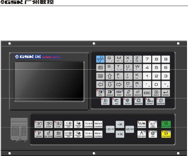
GSK928TEa Turning CNC System User Manual
Chapter Three Operation Panel
The turning CNC system(system or CNC) uses the aluminum alloy three-D operation panel and its appearance is as follows:
3.1LCD Display
LCD display: CNC man-machine dialogue interface. Resolution 480×234 lattice TFT color LCD display.
3.2LED Status Indicator
LED indicates that the current working state of the system. There are 16 function keys with LED indicators, the function executed by the corresponding key is valid when LED is ON, and it is invalid when LED is OFF.
3.3Keyboard
Based on GB/T 3168-1993 Numerical Control of Machine-Symbol, the system sets the following symbol function keys which complete the corresponding functions when they are pressed as follows:
3.3.1Character keys
Character keys include all required valid digit, letter, mathematic symbol and logic symbol.
In EDIT working mode, each letter key can switch into 2 or 3 letter keys; in other working mode, each
6
Operation |
Chapter Three System Operation Panel |
letter key only expresses one letter key. (For example, I and I are on one key, the operator directly press the key when “I” or “P” is required, and the system automatically indentifies other letters.)
Digit key: input all kind of data 0 9 ;
Letter key: input field, address, English letter;
Symbol key: +, -, *, /, minus sign, decimal and so on;
Logic key: , , , and, or, and so on.
3.3.2Working mode selection key
Marking with the symbols and characters, the working mode selection keys are pressed to complete the corresponding function, and their definitions are as follows:
 : select EDIT working mode
 : select JOG working mode
 : select AUTO working mode
 : select PARAMETER working mode
 : select OFFSET working mode
 : select DIAGNOSIS working mode
3.3.3Function keys
Press function keys with the visualization symbol and letter to complete the corresponding functions and each symbol definition is as follows:
 INCREASING RAPID OVERRIDE Increase rapid traverse override in JOG working mode and G00 rapid traverse override in AUTO working mode.
 REDUCING RAPID OVERRIDE: Reduce rapid traverse override in JOG working mode and G00 rapid traverse override in AUTO working mode.
 INCREASING FEEDRATE OVERRIDE: Increase feedrate override in JOG working mode and G01 feedrate override in AUTO working mode.
 REDUCING FEEDATE OVERRIDE: Reduce feedrate override in JOG working mode and
7

GSK928TEa Turning CNC System User Manual
G01 feedrate override in AUTO working mode.
 X PROGRAM REFERENCE POINT(PROGRAM ZERO) RETURN : It is valid in JOG /AUTO working mode. (program zero is called program reference point in the user manual.)
 Z PROGRAM REFERENCE POINT (PROGRAM ZERO) RETURN : It is valid in JOG /AUTO working mode.
 X MACHINE ZERO (MACHINE ZERO) RETURN : It is valid in JOG /AUTO working mode. (machine zero is called machine reference point in the user manual.)
 Z or Y MACHINE ZERO(MACHINE REFERENCE POINT) RETURN: It is valid in JOG /AUTO working mode.
DRY RUN: In AUTO working mode, whether M, S, T are valid is determined by the parameter (bit parameter P401_d7), each axis coordinates automatically recover to the previous ones before the system enters the DRY RUN working mode.
 SINGLE BLOCK: A single block runs in AUTO working mode. It is hp function in other working modes.
3.3.4Cycle start and cycle pause (feed hold)key
Start and pause programs in AUTO working mode and each key symbol definition is as follows:
 CYCLE START: Start to run programs in AUTO working mode; move coordinate axis in JOG working mode.
 CYCLE PAUSE (FEED HOLD ): pause the running in JOG or AUTO working mode; hp function in other working modes.
Note
There is “hp(help) at top right on some keys, and there are 7 help keys hp0 hp6 hp is valid when the main key is invalid in different working modes.
3.3.5Manual axis control key
Manual key symbol definitions in JOG working mode are as follows:
X axis moves negatively in JOG working mode.
 X axis moves positively in JOG working mode.
8
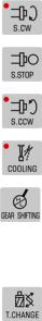
Operation |
Chapter Three System Operation Panel |
 Z or Y moves negatively in JOG working mode.
 Z or Y moves positively in JOG working mode.
 RAPID TRAVERSE/FEED Switching rapid traverse and feed in JOG working mode.
 JOG STEP Selecting each step width or MPG feed in STEP/ MPG(Handwheel) working mode; hp function in other working modes.
 MPG(Handwheel) MPG control selection and axis selection in JOG working mode; hp function in other working modes.
 Z/Y selection in JOG working mode; hp function in other working modes.
 STEP/JOG mode Switch STEP/JOG mode in JOG working mode.
3.3.6Manual auxiliary function key
The following press keys are used to controlling and completing all miscellaneous function of the machine and each key symbol definition is as follows:
Spindle rotation (CW) |
Spindle rotates clockwise. |
Spindle stop |
Spindle stops. |
Spindle rotation (CCW) |
Spindle rotates counterclockwise. |
Cooling control |
Switch cooling ON/OFF. |
Spindle gear shifting |
Select the speed of each gear when the machine is equipped |
|
with multi-gear (up to 16 gears) spindle motor and control |
|
loops. |
Tool change |
Select the next tool number neighboring to the current one. |
9
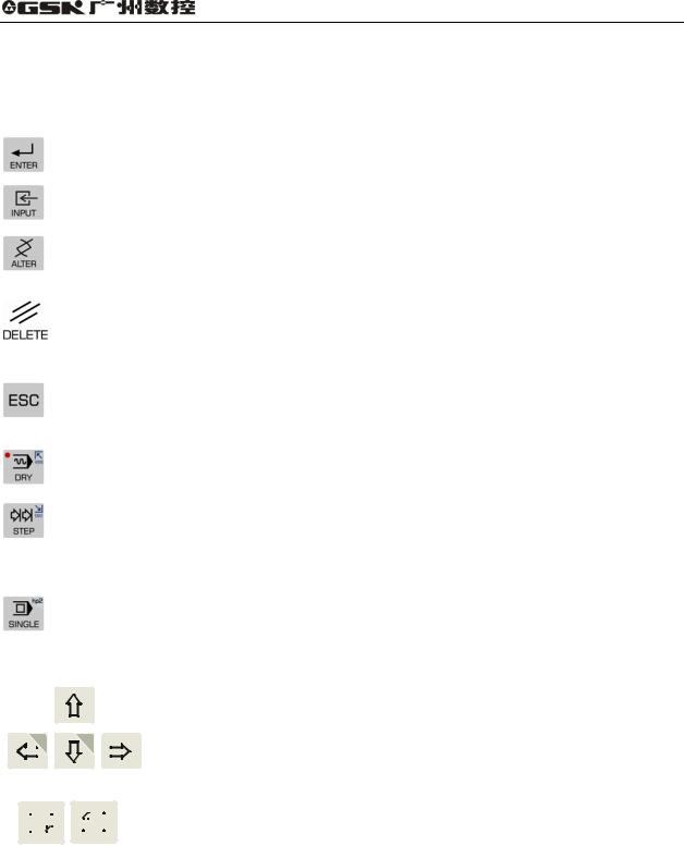
GSK928TEa Turning CNC System User Manual
3.3.7Edit keys
Press key |
|
|
|
|
|
|
|
|
|
|
|
|
Name |
Function explanation |
|
|
|
|
||||||||||||||||||||||
|
|
|
|
|
|
|
|
|
|
|
|
|
|
|
|
|
|
|
|
|
|
|
|
|
|
|
|
|
|
|
|
|
|
|
|
|||||
|
|
|
|
|
|
|
|
|
|
|
|
|
|
|
|
|
|
|
|
|
|
|
|
|
|
|
|
|
|
|
|
|
|
ENTER key |
Press it after the corresponding operation is performed. |
|||||
|
|
|
|
|
|
|
|
|
|
|
|
|
|
|
|
|
|
|
|
|
|
|
|
|
|
|
|
|
|
|
|
|
|
|
|
|
|
|
|
|
|
|
|
|
|
|
|
|
|
|
|
|
|
|
|
|
|
|
|
|
|
|
|
|
|
|
|
|
|
|
|
|
|
|
INPUT key |
Input the required content. |
|
|
|
|
|
|
|
|
|
|
|
|
|
|
|
|
|
|
|
|
|
|
|
|
|
|
|
|
|
|
|
|
|
|
|
|
|
|
|
|
|
|
|
|||
|
|
|
|
|
|
|
|
|
|
|
|
|
|
|
|
|
|
|
|
|
|
|
|
|
|
|
|
|
|
|
|
|
|
ALTER key |
Switch character insert/alter state |
in EDIT |
working mode; |
|||
|
|
|
|
|
|
|
|
|
|
|
|
|
|
|
|
|
|
|
|
|
|
|
|
|
|
|
|
|
|
|
|
|
|
Special definition in other working modes. |
|
|||||
|
|
|
|
|
|
|
|
|
|
|
|
|
|
|
|
|
|
|
|
|
|
|
|
|
|
|
|
|
|
|
|
|
|
|
|
|||||
|
|
|
|
|
|
|
|
|
|
|
|
|
|
|
|
|
|
|
|
|
|
|
|
|
|
|
|
|
|
|
|
|
|
|
|
|||||
|
|
|
|
|
|
|
|
|
|
|
|
|
|
|
|
|
|
|
|
|
|
|
|
|
|
|
|
|
|
|
|
|
|
|
Delete digit, letter, block or whole program in EDIT working |
|||||
|
|
|
|
|
|
|
|
|
|
|
|
|
|
|
|
|
|
|
|
|
|
|
|
|
|
|
|
|
|
|
|
|
|
DELETE key |
mode; |
|
|
|
|
|
|
|
|
|
|
|
|
|
|
|
|
|
|
|
|
|
|
|
|
|
|
|
|
|
|
|
|
|
|
|
|
|
|
|
|
Special definition in other working modes. |
|
||||
|
|
|
|
|
|
|
|
|
|
|
|
|
|
|
|
|
|
|
|
|
|
|
|
|
|
|
|
|
|
|
|
|
|
|
|
|
|
|
||
|
|
|
|
|
|
|
|
|
|
|
|
|
|
|
|
|
|
|
|
|
|
|
|
|
|
|
|
|
|
|
|
|
|
ESCAPE |
Cancel the current input |
data |
or |
escape from the working |
||
|
|
|
|
|
|
|
|
|
|
|
|
|
|
|
|
|
|
|
|
|
|
|
|
|
|
|
|
|
|
|
|
|
|
state; |
|
|
|
|
|
|
|
|
|
|
|
|
|
|
|
|
|
|
|
|
|
|
|
|
|
|
|
|
|
|
|
|
|
|
|
|
|
|
|
|
key |
|
|
|
|
|
|
|
|
|
|
|
|
|
|
|
|
|
|
|
|
|
|
|
|
|
|
|
|
|
|
|
|
|
|
|
|
|
|
|
|
escape from the current operation or setting. |
|
|||||
|
|
|
|
|
|
|
|
|
|
|
|
|
|
|
|
|
|
|
|
|
|
|
|
|
|
|
|
|
|
|
|
|
|
|
|
|||||
|
|
|
|
|
|
|
|
|
|
|
|
|
|
|
|
|
|
|
|
|
|
|
|
|
|
|
|
|
|
|
|
|
|
|
|
|
||||
|
|
|
|
|
|
|
|
|
|
|
|
|
|
|
|
|
|
|
|
|
|
|
|
|
|
|
|
|
|
|
|
|
|
HOME key |
“DRY RUN” in AUTO working mode; |
|
||||
|
|
|
|
|
|
|
|
|
|
|
|
|
|
|
|
|
|
|
|
|
|
|
|
|
|
|
|
|
|
|
|
|
|
Cursor moving the end of the line in EDIT working mode. |
||||||
|
|
|
|
|
|
|
|
|
|
|
|
|
|
|
|
|
|
|
|
|
|
|
|
|
|
|
|
|
|
|
|
|
|
|
||||||
|
|
|
|
|
|
|
|
|
|
|
|
|
|
|
|
|
|
|
|
|
|
|
|
|
|
|
|
|
|
|
|
|
|
|
|
|
|
|
||
|
|
|
|
|
|
|
|
|
|
|
|
|
|
|
|
|
|
|
|
|
|
|
|
|
|
|
|
|
|
|
|
|
|
END key |
“STEP” in JOG working mode; |
|
|
|
||
|
|
|
|
|
|
|
|
|
|
|
|
|
|
|
|
|
|
|
|
|
|
|
|
|
|
|
|
|
|
|
|
|
|
Cursor moving the end of the line in EDIT working mode. |
||||||
|
|
|
|
|
|
|
|
|
|
|
|
|
|
|
|
|
|
|
|
|
|
|
|
|
|
|
|
|
|
|
|
|
|
|
||||||
|
|
|
|
|
|
|
|
|
|
|
|
|
|
|
|
|
|
|
|
|
|
|
|
|
|
|
|
|
|
|
|
|
|
|
|
|||||
|
|
|
|
|
|
|
|
|
|
|
|
|
|
|
|
|
|
|
|
|
|
|
|
|
|
|
|
|
|
|
|
|
|
|
“SINGLE/CONTINUOUS” executing programs in AUTO |
|||||
|
|
|
|
|
|
|
|
|
|
|
|
|
|
|
|
|
|
|
|
|
|
|
|
|
|
|
|
|
|
|
|
|
|
SINGLE |
working mode; |
|
|
|
|
|
|
|
|
|
|
|
|
|
|
|
|
|
|
|
|
|
|
|
|
|
|
|
|
|
|
|
|
|
|
|
|
|
|
|
“SINGLE/CONTINUOUS” |
analog |
executing |
programs in |
|||
|
|
|
|
|
|
|
|
|
|
|
|
|
|
|
|
|
|
|
|
|
|
|
|
|
|
|
|
|
|
|
|
|
|
BLOCK key |
||||||
|
|
|
|
|
|
|
|
|
|
|
|
|
|
|
|
|
|
|
|
|
|
|
|
|
|
|
|
|
|
|
|
|
|
AUTO working mode; |
|
|
|
|
||
|
|
|
|
|
|
|
|
|
|
|
|
|
|
|
|
|
|
|
|
|
|
|
|
|
|
|
|
|
|
|
|
|
|
|
|
|
|
|
||
|
|
|
|
|
|
|
|
|
|
|
|
|
|
|
|
|
|
|
|
|
|
|
|
|
|
|
|
|
|
|
|
|
|
|
hp function in other working modes. |
|
||||
|
|
|
|
|
|
|
|
|
|
|
|
|
|
|
|
|
|
|
|
|
|
|
|
|
|
|
|
|
|
|
|
|
|
|
|
|
|
|||
|
|
|
|
|
|
|
|
|
|
|
|
|
|
|
|
|
|
|
|
|
|
|
|
|
|
|
|
|
|
|
|
|
|
Cursor |
Control cursor |
movement in |
EDIT/PARAMETER/OFFSET |
|||
|
|
|
|
|
|
|
|
|
|
|
|
|
|
|
|
|
|
|
|
|
|
|
|
|
|
|
|
|
|
|
|
|
|
|||||||
|
|
|
|
|
|
|
|
|
|
|
|
|
|
|
|
|
|
|
|
|
|
|
|
|
|
|
|
|
|
|
|
|
|
|||||||
|
|
|
|
|
|
|
|
|
|
|
|
|
|
|
|
|
|
|
|
|
|
|
|
|
|
|
|
|
|
|
|
|
|
working mode; |
|
|
|
|
|
|
|
|
|
|
|
|
|
|
|
|
|
|
|
|
|
|
|
|
|
|
|
|
|
|
|
|
|
1 |
|
|
|
|
|
|
movement |
|
|
|
|
|
|
|
|
|
|
|
|
|
|
|
|
|
|
|
|
|
|
|
|
|
|
|
|
|
|
|
|
|
|
|
|
|
|
|
|
|
|
|
|
|||
|
|
|
|
|
|
|
|
|
hp0 |
|
|
|
|
|
|
|
|
|
|
hp |
|
|
|
|
|
|
key |
Hp function or |
other special |
definitions in |
other working |
|||||||||
|
|
|
|
|
|
|
|
|
|
|
|
|
||||||||||||||||||||||||||||
|
|
|
|
|
|
|
|
|
|
|
|
|
|
|
|
|
|
|
|
|
|
|
|
|
|
|
|
|
|
|
|
|
|
|||||||
|
|
|
|
|
|
|
|
|
|
|
|
|
|
|
|
|
|
|
|
|
|
|
|
|
|
|
|
|
|
|
|
|
|
|||||||
|
|
|
|
|
|
|
|
|
|
|
|
|
|
|
|
|
|
|
|
|
|
|
|
|
|
|
|
|
|
|
|
|
|
modes. |
|
|
|
|
|
|
|
|
|
|
|
|
|
|
|
|
|
|
|
|
|
|
|
|
|
|
|
|
|
|
|
|
|
|
|
|
|
|
|
|
|
|
|
|
|
||
|
|
|
|
|
|
|
|
|
|
|
|
|
|
|
|
|
|
|
|
|
|
|
|
|
|
|
|
|
|
|
|
|
|
|
|
|
|
|
|
|
|
|
|
|
|
|
|
|
|
|
|
|
|
|
|
|
|
|
|
|
|
|
|
|
|
|
|
|
|
|
|
|
|
|
|
|
|||||
|
|
|
|
|
|
|
|
|
|
|
|
|
|
|
|
|
|
|
|
|
|
|
|
|
|
|
|
|
|
|
|
|
|
PAGE |
Display page up/down in EDIT/PARAMETER/OFFSET; |
|||||
|
|
|
|
|
|
|
|
|
|
|
|
|
|
|
|
|
|
|
|
|
|
|
|
|
|
|
|
|
|
|
|
|
|
|||||||
|
|
|
|
|
|
|
|
|
|
|
|
|
|
|
|
|
|
|
|
|
|
|
|
|
|
|
|
|
|
|
|
|
|
|||||||
|
|
|
|
|
|
|
|
|
|
|
|
|
|
|
|
|
|
|
|
|
|
|
|
|
|
|
|
|
|
|
|
|
|
UP/DOWN |
Special definition in JOG /AUTO working mode. |
|||||
|
|
|
|
|
|
|
|
|
|
|
|
|
|
|
|
|
|
|
|
|
|
|
|
|
|
|
|
|
|
|
|
|
|
|||||||
|
|
|
|
|
|
|
|
|
|
|
|
|
|
|
|
|
|
|
|
|
|
|
|
|
|
|
|
|
|
|
|
|
|
|||||||
|
|
|
|
|
|
|
|
|
|
|
|
|
|
|
|
|
|
|
|
|
|
|
|
|
|
|
|
|
|
|
|
|
|
|
|
|
|
|
|
|
10

Operation |
Chapter Four System Operation |
Chapter Four System Operation
This chapter introduces operations and notes of the system. Please read carefully before operation.
4.1System ON/OFF, Initial State, Modal, and Safe Protection
4.1.1Power on
There is not a power switch on the operation panel of the system. The operator installs it according to the different machine to avoid bad effects to CNC system owing to the impaction of power supply. Check before the system is turned on:
1)Ensure the machine state is normal;
2)Ensure the voltage meets the requirements;
3)Ensure the wiring is correct and firm.
The system is turned on as follows:
1) The master power switch of machine is turned on.
Switch on the power switch of the CNC system, and the system displays as Fig. 4-1. Press
any keys except for |
|
|
|
|
|
, and the system enters into EDIT working mode. |
|
|
|||||
|
|
Fig. 4-1 System initialization display window 2) The system orderly completes the following work after power-on:
zThe system controls the program loading.
zThe system automatically check itself and executes the initialization.
zThe system loads and checks parameters.
zI/O interface initialization.
zThe system loads and checks the operator programs.
Note
1 Must not press any keys on the system panel when the system is turned on, press
RESET key when the system enters the press key test window at the moment.
4.1.2Power off
The system is turned off as follows:
11

GSK928TEa Turning CNC System User Manual
1)The power switch of the CNC is turned off.
2)The power switch of the machine is turned off.
Check before the system is turned off:
1)X, Z, Y are in the stop state;
2)Miscellaneous function(spindle, cooling) OFF;
3)Turn off the power supply.
Note
1 The system should be checked itself and initialized when it is turned on firstly( it is completed by the machine manufacturer, and the operator cannot execute the operation, otherwise, the parameter set by the machine manufacture will lose).
2 Operations related to turn off the machine power supply are referred to the operator manual machine manufacturer.
4.1.3System, program initial and modal
4.1.3.1Initial and modal
The initial mode of the system is defined to be a special initial state of all functions set by itself when the system is turned on; all auxiliary functions do not execute the actual output.
The modal of the system is defined to be their kept states after the system executes all functions. Initial mode and modal of the system:
System state |
Initial mode |
Modal |
Machine coordinate system |
Keep last power-on state |
Keep till being changed |
of the system |
|
|
Tool nose coordinate system |
Keep last power-on state |
Keep till being changed |
of the system |
|
|
Cutting feedrate F |
In Auto mode 30mm/min |
Keep till being changed |
|
In JOG mode: Keep last power-on state |
|
Conversion spindle speed S |
Keep last power-on state |
Keep till being changed |
Spindle gear |
Shifting gear spindle gear S0 |
Keep till being changed |
|
Conversion spindle gear M41 |
|
MANUAL slow feed/rapid feed state |
Slow feed |
Keep till being changed |
Feedrate override |
Keep last power-on state |
Keep till being changed |
Rapid override |
Keep last power-on state |
Keep till being changed |
Spindle state |
M05 spindle stop |
Keep till being changed |
Cooling state |
M09 cooling OFF |
Keep till being changed |
Chuck state |
M11 chuck release |
Keep till being changed |
Lubricating state |
M33 lubricating OFF |
Keep till being changed |
T number state |
Keep last power-on state |
Keep till being changed |
Tailstock state |
M79 tailstock run-out state |
Keep till being changed |
Set spindle speed/position mode |
M48 |
Keep till being changed |
4.1.3.2Initial mode and modal of program
The initial mode is the automatic initialization setting state before the system executes the machining program; i.e. the initial default state of the default programming word and speed word.
Program initialization state of the system: G command G00, G40, G97, G98; Cutting speed 30mm/min; Miscellaneous function: current state;
System coordinates: current coordinates are those of the last automatic executing program or manual operation
12
 Loading...